JP6672011B2 - Vehicle air conditioner - Google Patents
Vehicle air conditioner Download PDFInfo
- Publication number
- JP6672011B2 JP6672011B2 JP2016034265A JP2016034265A JP6672011B2 JP 6672011 B2 JP6672011 B2 JP 6672011B2 JP 2016034265 A JP2016034265 A JP 2016034265A JP 2016034265 A JP2016034265 A JP 2016034265A JP 6672011 B2 JP6672011 B2 JP 6672011B2
- Authority
- JP
- Japan
- Prior art keywords
- thermistor
- refrigerant
- ptc thermistor
- heat exchanger
- accumulator
- Prior art date
- Legal status (The legal status is an assumption and is not a legal conclusion. Google has not performed a legal analysis and makes no representation as to the accuracy of the status listed.)
- Expired - Fee Related
Links
Images


Landscapes
- Resistance Heating (AREA)
- Air-Conditioning For Vehicles (AREA)
Description
本発明は、車両用空調装置に関するものである。 The present invention relates to a vehicle air conditioner.
電気自動車等、車両駆動源としてエンジンを具備していない車両においては、暖房時にエンジンの冷却水を利用することができないことから、ヒートポンプサイクルを利用した車両用空調装置が採用されている。この種の車両用空調装置では、コンプレッサから吐出される冷媒の流れを切り替えることで、冷房運転と暖房運転とを切り替えている。 In a vehicle such as an electric vehicle which does not have an engine as a vehicle drive source, a vehicle air conditioner using a heat pump cycle is employed because cooling water of the engine cannot be used during heating. In this type of vehicle air conditioner, switching between the cooling operation and the heating operation is performed by switching the flow of the refrigerant discharged from the compressor.
具体的に、暖房運転では、コンプレッサから吐出される冷媒が、室内熱交換器において放熱され、その後暖房用膨張弁で膨張させられた後、室外熱交換器において吸熱して、再びコンプレッサに吸入される。そして、空調空気は、室内熱交換器を通過することで加熱され、暖房として車室内に供給される。
一方、冷房運転では、コンプレッサで吐出される冷媒が、室外熱交換器において放熱され、その後冷房用膨張弁で膨張させられた後、室内熱交換器において吸熱して、再びコンプレッサに吸入される。そして、空調空気は、室内熱交換器を通過することで冷却され、冷房として車室内に供給される。
Specifically, in the heating operation, the refrigerant discharged from the compressor is radiated in the indoor heat exchanger, and then expanded by the heating expansion valve, absorbs heat in the outdoor heat exchanger, and is sucked into the compressor again. You. Then, the conditioned air is heated by passing through the indoor heat exchanger, and is supplied to the vehicle interior as heating.
On the other hand, in the cooling operation, the refrigerant discharged from the compressor is radiated in the outdoor heat exchanger, then expanded by the cooling expansion valve, absorbed in the indoor heat exchanger, and sucked into the compressor again. Then, the conditioned air is cooled by passing through the indoor heat exchanger, and is supplied to the vehicle interior as cooling.
ところで、上述した車両用空調装置では、暖房運転において、冷媒が室外熱交換器で室外雰囲気から吸熱するため、室外熱交換器に霜が付着するおそれがある。室外熱交換器に霜が付着すると、熱伝達率が低下して吸熱不足になるので、車室内の暖房が不十分になることがある。 By the way, in the above-described vehicle air conditioner, in the heating operation, the refrigerant absorbs heat from the outdoor atmosphere in the outdoor heat exchanger, so that frost may adhere to the outdoor heat exchanger. If frost adheres to the outdoor heat exchanger, the heat transfer coefficient is reduced and the heat absorption is insufficient, so that the heating of the vehicle interior may be insufficient.
そこで、室外熱交換器に霜が付着している場合に、室外熱交換器で冷媒を放熱させる除霜運転を行う構成が知られている。例えば、下記特許文献1では、除霜運転の際、コンプレッサの上流側に設けられたアキュムレータ内の冷媒をヒータによって加熱することで、室外熱交換器内での冷媒の圧力を上昇させる構成が開示されている。 Therefore, there is known a configuration in which, when frost is attached to the outdoor heat exchanger, a defrosting operation is performed in which the outdoor heat exchanger releases the refrigerant. For example, Patent Literature 1 below discloses a configuration in which a refrigerant in an accumulator provided on an upstream side of a compressor is heated by a heater during a defrosting operation to increase the pressure of the refrigerant in an outdoor heat exchanger. Have been.
しかしながら、アキュムレータ内に収容された液相の冷媒量は、ヒートポンプサイクルの運転負荷によって異なる。この場合、上述した特許文献1の構成では、アキュムレータの空焚き等を抑制するために、冷媒量に応じてヒータに供給する電力を制御する必要があると考える。その結果、アキュムレータ内の状態を広範囲に亘って監視する必要があり、ヒータの制御が複雑になるおそれがある。 However, the amount of liquid-phase refrigerant contained in the accumulator differs depending on the operation load of the heat pump cycle. In this case, in the configuration of Patent Document 1 described above, it is considered that it is necessary to control the electric power supplied to the heater in accordance with the amount of the refrigerant in order to suppress the burning of the accumulator and the like. As a result, it is necessary to monitor the state in the accumulator over a wide range, and control of the heater may be complicated.
そこで、本発明は、上述した事情に考慮してなされたもので、簡単、かつ効果的に除霜運転を行うことができる車両用空調装置を提供することを目的とする。 Therefore, the present invention has been made in consideration of the above-described circumstances, and has as its object to provide a vehicle air conditioner capable of performing a defrosting operation simply and effectively.
上記目的を達成するために、請求項1に記載した発明は、冷媒を圧縮して吐出するコンプレッサ(例えば、実施形態におけるコンプレッサ41)と、前記コンプレッサから吐出される冷媒により放熱する室内熱交換器(例えば、実施形態における室内熱交換器26)と、前記室内熱交換器から吐出される冷媒と室外雰囲気との間で熱交換を行う室外熱交換器(例えば、実施形態における室外熱交換器43)と、冷媒の流通方向における前記コンプレッサの上流側に配置され、冷媒の気液を分離するとともに、気相の冷媒を前記コンプレッサに向けて流通させるアキュムレータ(例えば、実施形態におけるアキュムレータ47)と、前記アキュムレータに設けられたPTCサーミスタ(例えば、実施形態におけるPTCサーミスタ62)と、を備え、前記アキュムレータは、冷媒を収容するケース(例えば、実施形態におけるケース61)と、前記ケースに設けられ、前記PTCサーミスタを収容するサーミスタ収容部(例えば、実施形態におけるサーミスタ収容部92)と、を備え、前記PTCサーミスタは、発熱素子(例えば、実施形態における発熱素子95)と、前記発熱素子を挟持する一対の電極板(例えば、実施形態における電極板96,97)と、を備え、前記PTCサーミスタは、向きを反転して設けられた一対の楔部材(例えば、実施形態における楔部材110,111)に挟持されるとともに、前記一対の楔部材が前記サーミスタ収容部の内面に面した状態で、前記サーミスタ収容部内に収容され、前記一対の楔部材は、前記PTCサーミスタ及び前記一対の楔部材の積層方向に沿う断面視で三角形状に形成され、前記一対の楔部材のうち、第1楔部材は、前記サーミスタ収容部の内面を向く面が前記サーミスタ収容部の内面形状に倣って形成される一方、前記PTCサーミスタを向く面が前記サーミスタ収容部の開口部に向かうに従い前記第1楔部材の厚さが薄くなる傾斜面とされ、前記一対の楔部材のうち、第2楔部材は、前記サーミスタ収容部の内面を向く面が前記サーミスタ収容部の内面形状に倣って形成される一方、前記PTCサーミスタを向く面が前記サーミスタ収容部の開口部に向かうに従い前記第2楔部材の厚さが厚くなる傾斜面とされ、前記室外熱交換器の除霜を行う除霜運転時において、前記コンプレッサから吐出される冷媒を、前記室外熱交換器で放熱するとともに、前記アキュムレータ内の冷媒を前記PTCサーミスタにより加熱する。
In order to achieve the above object, the invention described in claim 1 is a compressor (for example, the
請求項2に記載した発明では、前記サーミスタ収容部は、前記PTCサーミスタを前記発熱素子及び前記電極板の積層方向に挟持するカシメ部(例えば、実施形態における側壁部213a)を備えていてもよい。
In the invention described in
請求項3に記載した発明では、前記アキュムレータは、冷媒を収容する有底筒状の前記ケース(例えば、実施形態におけるケース61)と、前記ケースの筒部(例えば、実施形態における筒部64b)に形成され、前記筒部の径方向の内側に窪むとともに、前記PTCサーミスタを収容する前記サーミスタ収容部(例えば、実施形態におけるサーミスタ収容部92)と、を備えていてもよい。
In the invention described in claim 3, wherein the accumulator is a bottomed cylindrical the casing for accommodating the refrigerant (e.g.,
請求項4に記載した発明では、前記アキュムレータは、冷媒を収容する有底筒状の前記ケース(例えば、実施形態におけるケース301)を備え、前記PTCサーミスタは、前記ケースの底壁部(例えば、実施形態における底壁部303)に固定されていてもよい。
In the invention described in claim 4, wherein the accumulator is a bottomed cylindrical the casing for accommodating the refrigerant (e.g.,
請求項1に記載した構成によれば、除霜運転時において、アキュムレータに設けられたPTCサーミスタを作動させる。すると、PTCサーミスタで発生した熱により、アキュムレータ内に貯留された液相の冷媒が加熱される。これにより、液相の冷媒が蒸発して気相の冷媒となる。気相となった冷媒は、アキュムレータ内から流出した後、コンプレッサに吸入され、上述した除湿運転に供される。このように、除霜運転時において、PTCサーミスタを作動させることで、室外熱交換器43内を流通する気相の冷媒の流量を増加させることができる。これにより、室外熱交換器での放熱量を増加させ、除霜運転を効果的に行うことができる。
特に、アキュムレータ内の冷媒を加熱する手段としてPTCサーミスタを用いる構成とした。この構成によれば、例えばアキュムレータ内の液相の冷媒が少なくなる等して、発熱素子が所定の温度(キュリー温度)まで過熱した場合に、抵抗値が急増してPTCサーミスタへの電流の供給が自動的に制限される(OFF状態)。そのため、従来のように電力の複雑な制御を行うことなく、アキュムレータの空焚き等を抑制できる。その結果、簡単、かつ効果的に除霜運転を行うことができる。
According to the configuration described in claim 1, the PTC thermistor provided in the accumulator is operated during the defrosting operation. Then, the liquid-phase refrigerant stored in the accumulator is heated by the heat generated by the PTC thermistor. Thereby, the liquid-phase refrigerant evaporates to become a gas-phase refrigerant. The refrigerant in the gas phase flows out of the accumulator, is then sucked into the compressor, and is subjected to the above-described dehumidifying operation. As described above, by operating the PTC thermistor during the defrosting operation, the flow rate of the gas-phase refrigerant flowing in the
In particular, a configuration is used in which a PTC thermistor is used as means for heating the refrigerant in the accumulator. According to this configuration, when the heating element overheats to a predetermined temperature (Curie temperature) due to, for example, a decrease in the amount of liquid-phase refrigerant in the accumulator, the resistance value sharply increases and current is supplied to the PTC thermistor. Is automatically restricted (OFF state). For this reason, it is possible to suppress empty burning of the accumulator without performing complicated control of the electric power as in the related art. As a result, a simple and effective defrosting operation can be performed.
また、サーミスタ収容部の内面と、PTCサーミスタの電極板と、の間に楔部材が介在しているため、PTCサーミスタの発熱素子と各電極板を強固に密接させることができる。これにより、発熱素子から各電極板が離間するのを抑制し、長期に亘って安定した動作信頼性を確保できる。
また、サーミスタ収容部の内面と、PTCサーミスタの電極板と、の間に、楔部材が隙間なく配置されるので、PTCサーミスタで発生した熱をアキュムレータ内の冷媒に効果的に伝えることができる。
In addition , since the wedge member is interposed between the inner surface of the thermistor accommodating portion and the electrode plate of the PTC thermistor, the heating element of the PTC thermistor and each electrode plate can be firmly and closely contacted. Thereby, it is possible to suppress the separation of each electrode plate from the heating element, and to ensure stable operation reliability over a long period of time.
Further, since the wedge member is arranged without a gap between the inner surface of the thermistor accommodating portion and the electrode plate of the PTC thermistor, heat generated by the PTC thermistor can be effectively transmitted to the refrigerant in the accumulator.
請求項2に記載した構成によれば、PTCサーミスタがサーミスタ収容部内において、カシメ部によって積層方向で挟持されることで、PTCサーミスタの発熱素子と各電極板を強固に密接させることができる。これにより、発熱素子から各電極板が離間するのを抑制し、長期に亘って安定した動作信頼性を確保できる。
また、サーミスタ収容部におけるカシメ部の内面と、PTCサーミスタの電極板と、を接触させることで、PTCサーミスタで発生した熱をアキュムレータ内の冷媒に効果的に伝えることができる。
According to the configuration described in
Further, by contacting the inner surface of the caulking portion in the thermistor housing with the electrode plate of the PTC thermistor, heat generated by the PTC thermistor can be effectively transmitted to the refrigerant in the accumulator.
請求項3に記載した構成によれば、ケースの筒部に、径方向の内側に窪むサーミスタ収容部を形成することで、ケース内に収容される冷媒を効果的に加熱することができる。 According to the configuration described in claim 3 , by forming the thermistor accommodating portion depressed inward in the radial direction in the cylindrical portion of the case, the refrigerant accommodated in the case can be effectively heated.
請求項4に記載した構成によれば、ケースの底壁部にPTCサーミスタを取り付けることで、PTCサーミスタを簡単にケースに取り付けることができる。 According to the configuration described in claim 4 , by attaching the PTC thermistor to the bottom wall of the case, the PTC thermistor can be easily attached to the case.
次に、本発明の実施形態を図面に基づいて説明する。
(第1実施形態)
[車両用空調装置]
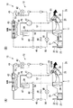
図1は車両用空調装置10の構成図である。
図1に示すように、本実施形態の車両用空調装置10は、例えば車両駆動源としてのエンジン(内燃機関)を具備していない車両(例えば、電気自動車等)に搭載されている。具体的に、車両用空調装置10は、空調ユニット11と、冷媒が循環可能なヒートポンプサイクル12と、を主に備えている。
Next, an embodiment of the present invention will be described with reference to the drawings.
(1st Embodiment)
[Vehicle air conditioner]
FIG. 1 is a configuration diagram of a
As shown in FIG. 1, the
空調ユニット11は、空調空気が流通するダクト21と、このダクト21内に収容された内外気ドア22、ブロワ23、エバポレータ24、エアミックスドア25及び室内熱交換器26と、を備えている。
ダクト21は、空調空気の流通方向のうち、上流側に形成された内気取込口31及び外気取込口32と、下流側に形成された吹き出し口33と、を有している。上述した内外気ドア22、ブロワ23、エバポレータ24、エアミックスドア25及び室内熱交換器26は、ダクト21内において流通方向の上流側から下流側にこの順で配置されている。
The
The
内外気ドア22は、内気取込口31を開放する内気取込位置と、外気取込口32を開放する外気取込位置と、の間を回動する。これにより、ダクト21内に流入する空調空気のうち、内気と外気の流量割合が調整される。
ブロワ23は、取込口31,32を通してダクト21内に取り込まれた空調空気(内気及び外気の少なくとも一方)を、下流側に送出する。
The inside /
The
エバポレータ24は、内部に流入した低圧の冷媒と車室内雰囲気(ダクト21内)との間で熱交換を行ない、例えば冷媒が蒸発する際の吸熱によって、エバポレータ24を通過する空調空気を冷却する。
The
室内熱交換器26は、内部に流入した高温かつ高圧の冷媒と車室内雰囲気(ダクト21内)との間で熱交換を行い、例えば室内熱交換器26を通過する空調空気を加熱する。
The
エアミックスドア25は、ダクト21内のうち、室内熱交換器26を通過して吹き出し口33に向かう通風経路(加熱経路)を開放する加熱位置(図5参照)と、室内熱交換器26を迂回して吹き出し口33に向かう通風経路(冷却経路)を開放する冷却位置(図6参照)と、の間で回動する。これにより、エバポレータ24を通過した空調空気のうち、加熱経路を通過する流量と、冷却経路を通過する流量と、の流量割合が調整される。
The
ヒートポンプサイクル12は、例えば、上述したエバポレータ24及び室内熱交換器26と、コンプレッサ41、暖房用膨張弁42、室外熱交換器43、暖房弁44、逆止弁45、冷房用膨張弁46、アキュムレータ47及び除湿弁48と、を備えている。ヒートポンプサイクル12の上述した各構成品は、冷媒流路49を介して接続されている。
The
コンプレッサ41は、アキュムレータ47と室内熱交換器26との間に接続されている。コンプレッサ41は、アキュムレータ47から気相の冷媒を吸入するとともに、この冷媒を圧縮した後、高温かつ高圧の冷媒として上述した室内熱交換器26に吐出する。
The
暖房用膨張弁42は、室内熱交換器26から吐出された冷媒を、膨張させた後、低温かつ低圧で気液2相(液相リッチ)の噴霧状の冷媒として室外熱交換器43に吐出する。
The
冷媒流路49には、暖房用膨張弁42を迂回するバイパス流路51が接続されている。バイパス流路51には、バイパス流路51内を流れる冷媒の流量を調整するバイパス弁52が設けられている。バイパス弁52は、暖房運転の実行時には閉状態とされ、冷房運転の実行時には開状態とされる。
これにより、例えば、暖房運転の実行時には、室内熱交換器26から排出された冷媒は暖房用膨張弁42を通過して低温かつ低圧の状態で室外熱交換器43に流入する。
一方、冷房運転の実行時には、室内熱交換器26から排出された冷媒はバイパス弁52を通過して高温の状態で室外熱交換器43に流入する。
A
Thus, for example, during execution of the heating operation, the refrigerant discharged from the
On the other hand, during execution of the cooling operation, the refrigerant discharged from the
室外熱交換器43は、内部に流入した冷媒と室外雰囲気との間で熱交換を行なう。具体的に、室外熱交換器43は、暖房運転の実行時において、内部に流入する低温かつ低圧の冷媒を室外雰囲気からの吸熱によって昇温する。一方、室外熱交換器43は、冷房運転の実行時において、内部に流入する高温の冷媒を室外雰囲気へと放熱によって冷却する。なお、室外熱交換器43は、室内熱交換器26に比べて冷媒の容量が大きくなっている。
The
室外熱交換器43と対向する位置には、室外熱交換器43に向けて送風可能なファン50が配設されている。また、上述した冷媒流路49は、室外熱交換器43の下流側において、冷房流路55、暖房流路56及び除湿流路57に分岐している。
At a position facing the
逆止弁45は、冷媒流路49のうち、上述した冷房流路55上に設置されている。逆止弁45は、冷房運転の実行時において、室外熱交換器43を通過した冷媒を下流側に向けて流通させる。一方、逆止弁45は、除湿運転の実行時において、除湿流路57から冷房流路55内に流入した冷媒の、逆止弁45よりも上流側(室外熱交換器43側)への逆流を防止する。
冷房用膨張弁46は、冷房流路55のうち、逆止弁45とエバポレータ24との間に接続されている。冷房用膨張弁46は、逆止弁45を通過した冷媒を、膨張させた後、低温かつ低圧で気液2相(気相リッチ)の噴霧状の冷媒としてエバポレータ24に吐出する。
The
The cooling
暖房弁44は、冷媒流路49のうち、上述した暖房流路56上に設置されている。暖房弁44は、暖房運転の実行時に開状態となり、冷房運転の実行時は閉状態となる。なお、暖房流路56は、暖房弁44の下流側で、冷房流路55におけるエバポレータ24の下流側に合流している。
The
アキュムレータ47は、冷媒流路49のうち、冷房流路55の下流端及び暖房流路56の下流端の間を接続する合流部59と、上述したコンプレッサ41と、の間に接続されている。アキュムレータ47は、合流部59から流入した冷媒の気液を分離し、気相の冷媒をコンプレッサ41に吸入させる。なお、アキュムレータ47の詳細な構成は、後述する。
The
除湿弁48は、上述した冷媒流路49のうち、除湿流路57上に設置される。除湿弁48は、除湿運転の実行時に開状態とされ、それ以外の運転(冷房運転及び暖房運転等)の実行時には閉状態とされる。なお、除湿流路57は、冷媒流路49のうち、冷房流路55における逆止弁45よりも下流側に位置する部分と、冷媒流路49のうち室内熱交換器26と暖房用膨張弁42との間に位置する部分と、を接続している。
The
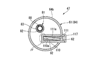
<アキュムレータ>
図2は、アキュムレータ47の径方向に沿う横断面図である。図3は、アキュムレータ47の軸方向に沿う縦断面図である。
図2、図3に示すように、アキュムレータ47は、冷媒を収容するケース61と、ケース61内の冷媒を加熱するPTC(Positive Temperature Coefficient)サーミスタ62と、を備えている。
<Accumulator>
FIG. 2 is a cross-sectional view of the
As shown in FIGS. 2 and 3, the
ケース61は、有底筒状のケース本体64と、ケース本体64の開口部を閉塞する蓋体65と、を備えている。なお、以下の説明では、ケース本体64の軸線に沿う方向を単に軸方向といい、軸線に直交する方向を径方向といい、軸線周りの方向を周方向という場合がある。また、本実施形態では、軸方向のうち、ケース本体64の底壁部64a側を下方とし、蓋体65側を上方として説明する。
The
図3に示すように、蓋体65には、蓋体65を軸方向に貫通する冷媒入口71及び冷媒出口72が形成されている。図1、図3に示すように、冷媒入口71には、上述した冷媒流路49のうち、合流部59の下流端が接続されている。冷媒出口72には、上述した冷媒流路49のうち、アキュムレータ47とコンプレッサ41とを接続する接続流路75の上流端が接続されている。
As shown in FIG. 3, the
図3に示すように、ケース61内には、ケース61内と冷媒出口72との間を連通させる連通配管81が設けられている。連通配管81は、内筒82と、内筒82の周囲を取り囲む外筒83と、を有している。
内筒82は、軸方向に沿って延在している。内筒82の上端部は、冷媒出口72に接続されている。
As shown in FIG. 3, a
The
外筒83は、内筒82と同軸上に配置された有底筒状に形成されている。外筒83は、内筒82の上部を露出させた状態で、内筒82を径方向の外側及び下方から取り囲んでいる。なお、外筒83は、図示しないリブ等によって内筒82に連結されている。
内筒82と外筒83との間の隙間は、内筒82の下端開口部と、外筒83の外側と、を接続する迂回流路88を構成している。迂回流路88は、ケース61内の冷媒のうち、液相の冷媒が内筒82内に流入するのを抑制する。一方、気相の冷媒は、外筒83の上方から迂回流路88内に流入する。
また、外筒83の底壁部には、底壁部を軸方向に貫通するオイル戻り孔89が形成されている。オイル戻り孔89は、ケース61内に収容された液相の冷媒中に含まれるオイル(潤滑油)を内筒82内に導くためのものである。
The
The gap between the
An
内筒82の上部(外筒83の上端縁よりも上方に位置する部分)には、バッフル90が設けられている。バッフル90は、軸方向から見た平面視において、ケース本体64の内径よりも小さい円形状に形成されている。バッフル90は、上述した冷媒入口71及び冷媒出口72に対して軸方向で間隔をあけた状態で対向している。なお、本実施形態では、バッフル90の外周縁と、ケース本体64における筒部64bの内周面と、の間を冷媒が通過可能となっている。但し、バッフル90自体に冷媒が通過可能な通過孔を設けても構わない。この場合、バッフル90は、ケース本体64の筒部64bに固定しても構わない。
A
図2、図3に示すように、ケース本体64における筒部64bの下部には、サーミスタ収容部92が形成されている。サーミスタ収容部92は、筒部64bの外周面に対して径方向の内側に窪んでいる。また、サーミスタ収容部92は、径方向のうち、第1方向から見て連通配管81と重ならない位置に形成されている。また、サーミスタ収容部92における径方向の内側端部は、径方向のうち、第1方向に直交する第2方向から見て連通配管81と重なる位置まで延在している。
As shown in FIGS. 2 and 3, a
図4は、図2のIV部拡大図である。
図4に示すように、PTCサーミスタ62は、発熱素子95と、発熱素子95を挟持する一対の電極板(第1電極板96及び第2電極板97)と、を備えている。
発熱素子95は、板状に形成されている。発熱素子95は、温度が上昇するにつれて電気抵抗が増大する素子である。発熱素子95としては、セラミック系材料や、樹脂とカーボンの混合材料等の材料が好適に用いられている。
電極板96,97は、発熱素子95のうち、対向する両面に各別に積層されている。電極板96,97には、電極板96,97に電力を供給するための図示しないリード線がそれぞれ接続されている。なお、以下の説明では、PTCサーミスタ62のうち、発熱素子95及び各電極板96,97の積層方向を単に積層方向という場合がある。
FIG. 4 is an enlarged view of a part IV in FIG.
As shown in FIG. 4, the
The
The
PTCサーミスタ62における積層方向の両面には、伝熱シート100がそれぞれ積層されている。伝熱シート100は、絶縁性を有し、かつ熱伝導性に優れた材料(例えば、シリコーン樹脂等)により構成されている。伝熱シート100は、PTCサーミスタ62の各電極板96,97に各別に密着している。なお、伝熱シート100は、積層方向から見た平面視でPTCサーミスタ62よりも大きくなっている。但し、伝熱シート100の平面視外形は、適宜変更が可能である。
PTCサーミスタ62の積層方向において、伝熱シート100を間に挟んでPTCサーミスタ62の反対側には、絶縁シート101がそれぞれ積層されている。絶縁シート101は、例えばアルミナ等により形成されている。絶縁シート101は、PTCサーミスタ62とケース61との間の絶縁を図っている。なお、絶縁シート101の平面視形状は、伝熱シート100と同等の大きさになっている。
In the stacking direction of the
ここで、上述したPTCサーミスタ62は、上述した伝熱シート100及び絶縁シート101とともに一対の楔部材(第1楔部材110及び第2楔部材111)によって積層方向に挟持された状態で、上述したサーミスタ収容部92内に嵌合されている。本実施形態において、PTCサーミスタ62は、積層方向に直交する面内方向のうち、第1延在方向をサーミスタ収容部92の開口方向に沿わせた状態で、サーミスタ収容部92内に嵌合されている。なお、各楔部材110,111は、アルミニウム合金等の熱伝導性に優れた材料により形成されていることが好ましい。
Here, the
第1楔部材110は、積層方向に沿う断面視で三角形状に形成されている。具体的に、第1楔部材110の外面のうち、サーミスタ収容部92の内面に面する部分は、サーミスタ収容部92の内面形状に倣って形成されている。一方、第1楔部材110の外面のうち、絶縁シート101に面する部分(以下、第1接触面110aという。)は、サーミスタ収容部92の開口部に向かうに従い第1楔部材110の厚さが薄くなる傾斜面とされている。この場合、PTCサーミスタ62は、第1電極板96側に位置する絶縁シート101及び伝熱シート100を介して第1楔部材110の第1接触面110aに接している。すなわち、PTCサーミスタ62は、第1延在方向がサーミスタ収容部92の開口方向に対して傾いた状態でサーミスタ収容部92内に配置されている。
The
第2楔部材111は、積層方向に沿う断面視で三角形状に形成されている。具体的に、第2楔部材111の外面のうち、サーミスタ収容部92の内面に面する部分は、サーミスタ収容部92の内面形状に倣って形成されている。一方、第2楔部材111の外面のうち、絶縁シート101に面する部分(以下、第2接触面111aという。)は、サーミスタ収容部92の開口部に向かうに従い第2楔部材111の厚さが厚くなる傾斜面とされている。この場合、PTCサーミスタ62は、第2電極板97側に位置する絶縁シート101及び伝熱シート100を介して第2楔部材111の第2接触面111aに接している。これにより、PTCサーミスタ62は、第1延在方向がサーミスタ収容部92の開口方向に対して傾き、かつ楔部材110,111に積層方向で挟持された状態でサーミスタ収容部92内に嵌合されている。
The
なお、上述したPTCサーミスタ62、各伝熱シート100、各絶縁シート101及び第2楔部材111は、保治具115によって積層方向で束ねられた状態で、サーミスタ収容部92内に挿入されている。すなわち、本実施形態のPTCサーミスタ62をサーミスタ収容部92内に嵌合する場合には、まずサーミスタ収容部92内に第1楔部材110を挿入する。その後、PTCサーミスタ62、各伝熱シート100、各絶縁シート101及び第2楔部材111を保治具115で束ねた状態で、サーミスタ収容部92内に挿入する。すると、PTCサーミスタ62等(各伝熱シート100や各絶縁シート101、第2楔部材111等)は、第1楔部材110の第1接触面110aに沿ってサーミスタ収容部92内に案内される。
The above-described
このとき、第1楔部材110の第1接触面110aと、サーミスタ収容部92の内面のうち積層方向で第1接触面110aと対向する部分と、の間の隙間は、サーミスタ収容部92の開口部から離間するに従い狭くなっている。そのため、PTCサーミスタ62等がサーミスタ収容部92内に進入するに従い、第2楔部材111がサーミスタ収容部92内に圧入されていく。これにより、PTCサーミスタ62が楔部材110,111に積層方向で挟持された状態でサーミスタ収容部92内に嵌合される。なお、楔部材は、少なくとも第2楔部材111を有していれば構わない。すなわち、PTCサーミスタ62のうち、第1電極板96側の面は、サーミスタ収容部92の内面に密接する構成であっても構わない。
At this time, the gap between the
第1延在方向におけるPTCサーミスタ62の発熱素子95と保治具115との間には、PTCサーミスタ62と保治具115やサーミスタ収容部92との絶縁を図るスペーサ116が配置されている。また、図2に示すように、サーミスタ収容部92の開口部には、キャップ材117が設けられている。キャップ材117は、PTCサーミスタ62の抜け止めを行うとともに、上述した図示しないリード線等が保持される。
Between the
[車両用空調装置の動作方法]
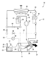
次に、上述した車両用空調装置10の動作について説明する。図5は、車両用空調装置10の暖房運転を説明するための説明図である。なお、以下の各説明図において、冷媒流路49のうち、鎖線部分は高圧の冷媒が流通する部分を示し、実線部分は低圧の冷媒が流通する部分を示し、破線部分は冷媒が流通しない部分を示している。
(暖房運転)
始めに、車両用空調装置10の暖房運転について説明する。
図5に示すように、暖房運転時において、エアミックスドア25は加熱位置とされ、暖房弁44は開状態とされる。なお、暖房運転時において、バイパス弁52及び除湿弁48は閉状態とされる。
[Operation method of vehicle air conditioner]
Next, the operation of the above-described
(Heating operation)
First, the heating operation of the
As shown in FIG. 5, during the heating operation, the
この場合、コンプレッサ41から吐出された高温かつ高圧の冷媒は、室内熱交換器26における放熱によってダクト21内の空調空気を加熱する。
そして、冷媒は、暖房用膨張弁42によって膨張させられて気液2相(液相リッチ)の噴霧状とされる。その後、冷媒は、室外熱交換器43において室外雰囲気から吸熱して気液2相(気相リッチ)の噴霧状となる。室外熱交換器43を通過した冷媒は、暖房流路56において暖房弁44を通過した後、合流部59を通してアキュムレータ47に流入する。
そして、冷媒は、アキュムレータ47において気液分離され、気相の冷媒がコンプレッサ41に吸入される。
In this case, the high-temperature and high-pressure refrigerant discharged from the
The refrigerant is expanded by the
Then, the refrigerant is gas-liquid separated in the
次に、暖房運転における空調空気の流れを説明する。なお、暖房運転において、ダクト21内に取り入れる空調空気は、内気であっても外気であっても構わない。
ブロワ23を駆動させると、取込口31,32を通してダクト21内に空調空気が流入する。ダクト21内に流入した空調空気は、エバポレータ24を通過した後、加熱経路内で室内熱交換器26を通過する。そして、空調空気は、加熱経路内において、室内熱交換器26を通過する際に加熱された後、吹き出し口33を通って車室内に暖房として供給される。
Next, the flow of the conditioned air in the heating operation will be described. In the heating operation, the conditioned air taken into the
When the
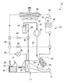
(冷房運転)
次に、車両用空調装置10の冷房運転について説明する。図6は、車両用空調装置10の冷房運転を説明するための説明図である。
図6に示すように、冷房運転時において、エアミックスドア25は冷却位置とされるとともに、バイパス弁52は開状態とされる。なお、暖房弁44及び除湿弁48は閉状態とされる。
(Cooling operation)
Next, the cooling operation of the
As shown in FIG. 6, during the cooling operation, the
この場合、コンプレッサ41から吐出された高温かつ高圧の冷媒は、室内熱交換器26とバイパス弁52とを通過する。その後、冷媒は、室外熱交換器43において室外雰囲気へと放熱された後、冷房流路55内に流入する。そして、冷媒は、冷房用膨張弁46によって膨張させられて気液2相(液相リッチ)の噴霧状とされる。その後、冷媒は、エバポレータ24における吸熱によってダクト21内の空調空気を冷却する。
そして、エバポレータ24を通過した気液2相(気相リッチ)の冷媒は、冷房用膨張弁46を通過した気液2相(液相リッチ)の冷媒との間で熱交換された後、アキュムレータ47内に流入する。その後、冷媒は、アキュムレータ47において気液分離された後、気相の冷媒がコンプレッサ41に吸入される。
In this case, the high-temperature and high-pressure refrigerant discharged from the
The gas-liquid two-phase (gas-phase rich) refrigerant that has passed through the
次に、上述した冷房運転時における空調空気の流れを説明する。なお、冷房運転において、ダクト21内に取り入れる空調空気は、内気であっても外気であっても構わない。
ダクト21内に流通した空調空気は、エバポレータ24を通過する際に冷却される。その後、空調空気は、室内熱交換器26を迂回した後、吹き出し口33を通って車室内に冷房として供給される。
Next, the flow of the conditioned air during the above-described cooling operation will be described. Note that, in the cooling operation, the conditioned air taken into the
The conditioned air flowing through the
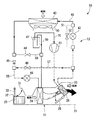
(除湿運転)
次に、車両用空調装置10の除湿運転について説明する。図7は、車両用空調装置10の除湿運転を説明するための説明図である。
図7に示すように、除湿運転時において、エアミックスドア25は加熱位置とされ、暖房弁44、除湿弁48は開状態とされる。なお、除湿運転時において、バイパス弁52は閉状態とされる。
(Dehumidification operation)
Next, the dehumidifying operation of the
As shown in FIG. 7, during the dehumidification operation, the
この場合、コンプレッサ41から吐出された高温かつ高圧の冷媒は、室内熱交換器26における放熱によってダクト21内の空調空気を加熱する。
そして、室内熱交換器26を通過した冷媒のうち、一方の冷媒は室外熱交換器43に向けて流通し、他方の冷媒は除湿流路57内に流入する。
In this case, the high-temperature and high-pressure refrigerant discharged from the
Then, among the refrigerants that have passed through the
具体的に、一方の冷媒は、上述した暖房運転と同様に、暖房用膨張弁42によって膨張させられた後、室外熱交換器43において室外雰囲気から吸熱する。
また、他方の冷媒は、除湿流路57を通して冷房流路55内に流入した後、上述した冷房運転と同様に、冷房用膨張弁46によって膨張させられた後、エバポレータ24において吸熱する。
その後、一方の冷媒及び他方の冷媒は、合流部59において合流した後、アキュムレータ47内に流入し、気相の冷媒のみがコンプレッサ41に吸入される。
Specifically, one refrigerant is expanded by the
The other refrigerant flows into the cooling
Thereafter, the one refrigerant and the other refrigerant merge at the
次に、上述した除湿運転時における空調空気の流れを説明する。
ダクト21内に流通した空調空気は、エバポレータ24を通過する際に冷却される。このとき、エバポレータ24を通過する空調空気は、露点以下まで冷却されることで、除湿される。その後、除湿された空調空気は、加熱経路を通過した後、吹き出し口33を通って車室内に除湿暖房として供給される。
Next, the flow of the conditioned air during the above-described dehumidifying operation will be described.
The conditioned air flowing through the
(除霜運転)
次に、除霜運転について説明する。図8は、車両用空調装置10の除霜運転を説明するための説明図であって、(A)はホットガス運転、(B)は逆転除霜運転を示している。
本実施形態の除霜運転では、いわゆるホットガス運転と、逆転除霜運転と、の少なくとも一方を行うことができる。
(Defrosting operation)
Next, the defrosting operation will be described. Drawing 8 is an explanatory view for explaining the defrosting operation of
In the defrosting operation of the present embodiment, at least one of a so-called hot gas operation and a reverse rotation defrosting operation can be performed.
(ホットガス運転)
図8(A)に示すホットガス運転では、暖房用膨張弁42を大口径で開弁して、コンプレッサ41で圧縮された冷媒(ホットガス)をそのまま室外熱交換器43に流入させる点で、上述した暖房運転と異なっている。
(Hot gas operation)
In the hot gas operation shown in FIG. 8A, the
具体的に、コンプレッサ41で圧縮された高温かつ高圧の冷媒は、室内熱交換器26における放熱によってダクト21内の空調空気を加熱する。室内熱交換器26から流出した冷媒は、暖房用膨張弁42を通過して室外熱交換器43に流入する。このとき、暖房用膨張弁42は大口径で開弁しているので、冷媒は暖房用膨張弁42で膨張せず、高圧かつ高温のまま室外熱交換器43に流入する。これにより、冷媒は室外熱交換器43で放熱されるため、室外熱交換器43の除霜を行うことができる。なお、室外熱交換器43を通過した冷媒は、上述した暖房運転と同様の流通経路を経てコンプレッサ41に戻る。
Specifically, the high-temperature and high-pressure refrigerant compressed by the
次に、上述したホットガス運転において、空調空気は、上述した暖房運転時と同様に、加熱経路内で室内熱交換器26によって加熱された後、車室内に供給される。なお、ホットガス運転において、ダクト21内に取り入れられる空調空気は、外気であることが好ましい。
Next, in the above-described hot gas operation, the conditioned air is heated in the heating path by the
(逆転除霜運転)
図8(B)に示す逆転除霜運転では、エアミックスドア25を加熱位置にする点で、上述した冷房運転と異なっている。
具体的に、コンプレッサ41から吐出された高温かつ高圧の冷媒は、室内熱交換器26とバイパス弁52とを通過して、室外熱交換器43において室外雰囲気へと放熱される。そして、冷媒が室外熱交換器43で放熱される際に、室外熱交換器43の除霜が行われる。その後、冷媒は、冷房用膨張弁46によって膨張させられた後、エバポレータ24における吸熱によってダクト21内の空調空気を冷却する。なお、エバポレータ24を通過した冷媒は、上述した冷房運転と同様の流通経路を経てコンプレッサ41に戻る。
(Reverse defrosting operation)
The reverse rotation defrosting operation shown in FIG. 8B is different from the above-described cooling operation in that the
Specifically, the high-temperature and high-pressure refrigerant discharged from the
上述した逆転除霜運転における空調空気の流れは、上述したホットガス運転における空調空気の流れと同様である。すなわち、ダクト21内を流通する空調空気は、加熱経路内で室内熱交換器26によって加熱された後、車室内に供給される。
The flow of the conditioned air in the above-described reverse defrosting operation is the same as the flow of the conditioned air in the above-described hot gas operation. That is, the conditioned air flowing through the
ここで、図2、図3に示すように、本実施形態では、上述した除霜運転時において、アキュムレータ47に取り付けられたPTCサーミスタ62を作動させる。すると、PTCサーミスタ62で発生した熱により、アキュムレータ47内に貯留された液相の冷媒が加熱される。これにより、液相の冷媒が蒸発して気相の冷媒となる。気相となった冷媒は、アキュムレータ47内において外筒83の上方から迂回流路88内に流入する。迂回流路88内に流入した冷媒は、迂回流路88内を下方に向けて流通した後、内筒82内に流入する。内筒82内に流入した気相の冷媒は、冷媒出口72を通して冷媒流路49上に流出する。その後、冷媒は、コンプレッサ41に吸入された後、上述した除湿運転に供される。
Here, as shown in FIGS. 2 and 3, in the present embodiment, the
このように、本実施形態では、除霜運転時において、PTCサーミスタ62を作動させることで、ヒートポンプサイクル12内を流通する気相の冷媒の流量を増加させることができる。これにより、室外熱交換器43での放熱量を増加させ、除霜運転を効果的に行うことができる。
特に、本実施形態では、アキュムレータ47内の冷媒を加熱する手段としてPTCサーミスタ62を用いる構成とした。この構成によれば、例えばアキュムレータ47内の液相の冷媒が少なくなる等して、発熱素子95が所定の温度(キュリー温度)まで過熱した場合に、抵抗値が急増してPTCサーミスタ62への電流の供給が自動的に制限される(OFF状態)。そのため、従来のように電力の複雑な制御を行うことなく、アキュムレータ47の空焚き等を抑制できる。その結果、簡単、かつ効果的に除霜運転を行うことができる。
As described above, in the present embodiment, by operating the
Particularly, in the present embodiment, the
本実施形態では、サーミスタ収容部92の内面と、PTCサーミスタ62の電極板96と、の間に楔部材110,111が介在しているため、PTCサーミスタ62の発熱素子95と各電極板96,97を強固に密接させることができる。これにより、発熱素子95から各電極板96,97が離間するのを抑制し、長期に亘って安定した動作信頼性を確保できる。
また、サーミスタ収容部92の内面と、PTCサーミスタ62の電極板96,97と、の間に、楔部材110,111が隙間なく配置されるので、PTCサーミスタ62で発生した熱をアキュムレータ47内の冷媒に効果的に伝えることができる。
In the present embodiment, since the
Further, since the
本実施形態では、ケース本体64の筒部64bに、径方向の内側に窪むサーミスタ収容部92を形成することで、ケース61内に収容される冷媒を効果的に加熱することができる。
In the present embodiment, the refrigerant contained in the
(第2実施形態)
次に、本発明の第2実施形態について説明する。図9は、第2実施形態に係るアキュムレータ200の縦断面図である。本実施形態では、PTCサーミスタ62をサーミスタ収容部213にカシメ固定する点で上述した第1実施形態と相違している。なお、以下の説明では、上述した第1実施形態と同様の構成については同一の符号を付して説明を省略する。
図9に示すアキュムレータ200のケース210において、ケース本体215は、筒部211と、筒部211の下端開口部を閉塞する底部材212と、を有している。
(2nd Embodiment)
Next, a second embodiment of the present invention will be described. FIG. 9 is a longitudinal sectional view of an
In the
底部材212には、上方に向けて窪むサーミスタ収容部213が設けられている。サーミスタ収容部213は、軸方向から見て上述した連通配管81と重ならない位置に形成されている。サーミスタ収容部213は、底部材212の下面上で開口している
The
PTCサーミスタ62は、サーミスタ収容部213内に下方から挿入されている。PTCサーミスタ62は、サーミスタ収容部213における積層方向で対向する側壁部(カシメ部)213aによってカシメ固定されている。これにより、PTCサーミスタ62は、サーミスタ収容部213内で保持されている。
The
本実施形態によれば、PTCサーミスタ62がサーミスタ収容部213内において、積層方向でカシメ固定されているため、PTCサーミスタ62の発熱素子95と各電極板96,97を強固に密接させることができる。これにより、発熱素子95から各電極板96,97が離間するのを抑制し、長期に亘って安定した動作信頼性を確保できる。
また、サーミスタ収容部213における側壁部213aの内面と、PTCサーミスタ62の電極板96,97と、を接触させることで、PTCサーミスタ62で発生した熱をアキュムレータ200内の冷媒に効果的に伝えることができる。
さらに、本実施形態では、サーミスタ収容部213の側壁部213aをカシメ部として用いることで、楔部材110,111を別途用いる場合に比べて部品点数の削減を図ることができる。
According to this embodiment, since the
Further, by contacting the inner surface of the
Further, in the present embodiment, by using the
なお、図10に示すアキュムレータ250のように、蓋部材251にサーミスタ収容部252を設けても構わない。この場合においても、サーミスタ収容部252のうち、PTCサーミスタ62に対して積層方向で対向する側壁部252aによってPTCサーミスタ62をカシメ固定することで、上述した第2実施形態と同様の作用効果を奏することができる。
In addition, like the
(第3実施形態)
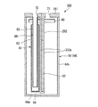
次に、本発明の第3実施形態について説明する。図11は、第3実施形態に係るアキュムレータ300の断面図である。本実施形態では、PTCサーミスタ62をケース301に下方から固定する点で上述した実施形態と相違している。
図11に示すアキュムレータ300のケース301において、ケース本体302の底壁部303には、PTCサーミスタ62を底壁部303に固定するための固定部材310が設けられている。
(Third embodiment)
Next, a third embodiment of the present invention will be described. FIG. 11 is a sectional view of an
In the
固定部材310は、軸方向から見た平面視において、底壁部303と同等の外径を有する円板状に形成されている。固定部材310には、下方に窪むサーミスタ収容部311が形成されている。サーミスタ収容部311内には、PTCサーミスタ62が積層方向を軸方向に向けた状態で収容されている。固定部材310は、底壁部303を下方から覆うとともに、底壁部303との間でPTCサーミスタ62を軸方向で挟持した状態で、底壁部303に固定されている。
The fixing
本実施形態によれば、上述した実施形態と同様の作用効果を奏するとともに、ケース本体302の外側からPTCサーミスタ62を取り付けることで、PTCサーミスタ62を簡単にケース301に取り付けることができる。
According to this embodiment, the same operation and effect as those of the above-described embodiment can be obtained, and the
なお、本発明の技術範囲は、上述した各実施形態に限定されるものではなく、本発明の趣旨を逸脱しない範囲において、上述した実施形態に種々の変更を加えたものを含む。すなわち、上述した実施形態で挙げた構成等はほんの一例に過ぎず、適宜変更が可能である。
例えば、上述した実施形態では、エンジンを具備していない車両として、電気自動車を例にして説明したが、これに限らず、燃料電池自動車に本発明の車両用空調装置10を採用しても構わない。また、エンジンを具備する車両に本発明の車両用空調装置10を採用しても構わない。
Note that the technical scope of the present invention is not limited to the above embodiments, and includes various modifications of the above embodiments without departing from the spirit of the present invention. That is, the configurations and the like described in the above-described embodiments are merely examples, and can be appropriately changed.
For example, in the above-described embodiment, an electric vehicle is described as an example of a vehicle not equipped with an engine. However, the present invention is not limited to this, and the
上述した実施形態では、PTCサーミスタ62が楔部材110,111やカシメ部、固定部材310によって積層方向に挟持されている構成について説明したが、これに限らず、PTCサーミスタ62によって冷媒を加熱する構成であれば構わない。
この場合、PTCサーミスタ62は、積層方向に限らず、積層方向に直交する面内方向で保持されていても構わない。
上述した実施形態では、PTCサーミスタ62を1つ設けた場合について説明したが、これに限らず、PTCサーミスタ62を複数設ける構成であっても構わない。
In the above-described embodiment, the configuration in which the
In this case, the
In the above-described embodiment, the case where one
その他、本発明の趣旨を逸脱しない範囲で、上述した実施形態における構成要素を周知の構成要素に置き換えることは適宜可能であり、また、上述した各変形例を適宜組み合わせてもよい。 In addition, it is possible to appropriately replace the components in the above-described embodiment with well-known components without departing from the spirit of the present invention, and the above-described modifications may be appropriately combined.
10…車両用空調装置
26…室内熱交換器
41…コンプレッサ
43…室外熱交換器
47,200,250,300…アキュムレータ
61,210,301…ケース
62…PTCサーミスタ
64b…筒部
92,213,252,311…サーミスタ収容部
95…発熱素子
96…第1電極板(電極板)
97…第2電極板(電極板)
110…第1楔部材(楔部材)
111…第2楔部材(楔部材)
213a,252a…側壁部(カシメ部)
303…底壁部
DESCRIPTION OF
97 second electrode plate (electrode plate)
110 ... 1st wedge member (wedge member)
111: second wedge member (wedge member)
213a, 252a ... side wall (caulking)
303 ... Bottom wall
Claims (4)
前記コンプレッサから吐出される冷媒により放熱する室内熱交換器と、
前記室内熱交換器から吐出される冷媒と室外雰囲気との間で熱交換を行う室外熱交換器と、
冷媒の流通方向における前記コンプレッサの上流側に配置され、冷媒の気液を分離するとともに、気相の冷媒を前記コンプレッサに向けて流通させるアキュムレータと、
前記アキュムレータに設けられたPTCサーミスタと、を備え、
前記アキュムレータは、
冷媒を収容するケースと、
前記ケースに設けられ、前記PTCサーミスタを収容するサーミスタ収容部と、を備え、
前記PTCサーミスタは、
発熱素子と、
前記発熱素子を挟持する一対の電極板と、を備え、
前記PTCサーミスタは、向きを反転して設けられた一対の楔部材に挟持されるとともに、前記一対の楔部材が前記サーミスタ収容部の内面に面した状態で、前記サーミスタ収容部内に収容され、
前記一対の楔部材は、前記PTCサーミスタ及び前記一対の楔部材の積層方向に沿う断面視で三角形状に形成され、
前記一対の楔部材のうち、第1楔部材は、前記サーミスタ収容部の内面を向く面が前記サーミスタ収容部の内面形状に倣って形成される一方、前記PTCサーミスタを向く面が前記サーミスタ収容部の開口部に向かうに従い前記第1楔部材の厚さが薄くなる傾斜面とされ、
前記一対の楔部材のうち、第2楔部材は、前記サーミスタ収容部の内面を向く面が前記サーミスタ収容部の内面形状に倣って形成される一方、前記PTCサーミスタを向く面が前記サーミスタ収容部の開口部に向かうに従い前記第2楔部材の厚さが厚くなる傾斜面とされ、
前記室外熱交換器の除霜を行う除霜運転時において、前記コンプレッサから吐出される冷媒を、前記室外熱交換器で放熱するとともに、前記アキュムレータ内の冷媒を前記PTCサーミスタにより加熱することを特徴とする車両用空調装置。 A compressor that compresses and discharges the refrigerant;
An indoor heat exchanger that radiates heat by a refrigerant discharged from the compressor,
An outdoor heat exchanger that performs heat exchange between the refrigerant discharged from the indoor heat exchanger and an outdoor atmosphere,
An accumulator that is arranged upstream of the compressor in the direction of flow of the refrigerant, separates gas-liquid of the refrigerant, and circulates gas-phase refrigerant toward the compressor.
A PTC thermistor provided in the accumulator,
The accumulator is:
A case for containing a refrigerant,
A thermistor housing portion provided in the case and housing the PTC thermistor;
The PTC thermistor,
A heating element,
A pair of electrode plates sandwiching the heating element,
The PTC thermistor is sandwiched between a pair of wedge members provided in a reversed direction, and is housed in the thermistor housing portion with the pair of wedge members facing the inner surface of the thermistor housing portion,
The pair of wedge members are formed in a triangular shape in a sectional view along a stacking direction of the PTC thermistor and the pair of wedge members,
Among the pair of wedge members, the first wedge member has a surface facing the inner surface of the thermistor housing portion formed according to the inner surface shape of the thermistor housing portion, and a surface facing the PTC thermistor has a surface facing the thermistor housing portion. The first wedge member has a slope that becomes thinner toward the opening.
Of the pair of wedge members, the second wedge member has a surface facing the inner surface of the thermistor housing portion formed according to the inner surface shape of the thermistor housing portion, and a surface facing the PTC thermistor has a surface facing the thermistor housing portion. The slope of the second wedge member becomes thicker toward the opening of the second wedge member,
During a defrosting operation for defrosting the outdoor heat exchanger, the refrigerant discharged from the compressor is radiated by the outdoor heat exchanger, and the refrigerant in the accumulator is heated by the PTC thermistor. Vehicle air conditioner.
冷媒を収容する有底筒状の前記ケースと、
前記ケースの筒部に形成され、前記筒部の径方向の内側に窪むとともに、前記PTCサーミスタを収容する前記サーミスタ収容部と、を備えていることを特徴とする請求項1又は請求項2に記載の車両用空調装置。 The accumulator is:
The case having a bottomed cylindrical shape for storing a refrigerant,
The said thermistor accommodating part formed in the cylinder part of the said case, and hollowing in the radial direction of the said cylinder part, and accommodating the said PTC thermistor, The said thermistor accommodation part is provided, An air conditioner for a vehicle as described in the above.
前記PTCサーミスタは、前記ケースの底壁部に固定されていることを特徴とする請求項1から請求項3の何れか1項に記載の車両用空調装置。 The accumulator includes the bottomed cylindrical case that stores a refrigerant,
The vehicle air conditioner according to any one of claims 1 to 3, wherein the PTC thermistor is fixed to a bottom wall of the case.
Priority Applications (1)
| Application Number | Priority Date | Filing Date | Title |
|---|---|---|---|
| JP2016034265A JP6672011B2 (en) | 2016-02-25 | 2016-02-25 | Vehicle air conditioner |
Applications Claiming Priority (1)
| Application Number | Priority Date | Filing Date | Title |
|---|---|---|---|
| JP2016034265A JP6672011B2 (en) | 2016-02-25 | 2016-02-25 | Vehicle air conditioner |
Publications (2)
| Publication Number | Publication Date |
|---|---|
| JP2017149294A JP2017149294A (en) | 2017-08-31 |
| JP6672011B2 true JP6672011B2 (en) | 2020-03-25 |
Family
ID=59738780
Family Applications (1)
| Application Number | Title | Priority Date | Filing Date |
|---|---|---|---|
| JP2016034265A Expired - Fee Related JP6672011B2 (en) | 2016-02-25 | 2016-02-25 | Vehicle air conditioner |
Country Status (1)
| Country | Link |
|---|---|
| JP (1) | JP6672011B2 (en) |
Family Cites Families (4)
| Publication number | Priority date | Publication date | Assignee | Title |
|---|---|---|---|---|
| JPH0323768U (en) * | 1989-07-13 | 1991-03-12 | ||
| JPH097738A (en) * | 1995-06-15 | 1997-01-10 | Matsushita Electric Works Ltd | Heater |
| JP3815302B2 (en) * | 2001-11-12 | 2006-08-30 | 株式会社デンソー | Air conditioner for vehicles |
| JP2015155277A (en) * | 2014-02-21 | 2015-08-27 | 本田技研工業株式会社 | Air conditioner for vehicles |
-
2016
- 2016-02-25 JP JP2016034265A patent/JP6672011B2/en not_active Expired - Fee Related
Also Published As
| Publication number | Publication date |
|---|---|
| JP2017149294A (en) | 2017-08-31 |
Similar Documents
| Publication | Publication Date | Title |
|---|---|---|
| US10557660B2 (en) | Heat exchanger with a plurality of heat exchanging portions | |
| EP2990740B1 (en) | Air conditioning system | |
| US9862251B2 (en) | Vehicular air-conditioning system with a switching heat exchanger | |
| EP3025885B1 (en) | Vehicle air conditioner | |
| JP2007069733A (en) | Heating element cooling system using air conditioner for vehicle | |
| US7155927B2 (en) | Exhaust heat utilizing refrigeration system | |
| JP2012144245A (en) | Heat exchange system | |
| JP2013217631A (en) | Refrigeration cycle device | |
| WO2014087645A1 (en) | Vehicle heat pump device, and vehicle air-conditioning device | |
| US10086677B2 (en) | Vehicle air conditioning device, electric compressor, and vehicle air conditioning method | |
| JP6103186B2 (en) | VEHICLE HEAT PUMP DEVICE AND VEHICLE AIR CONDITIONER | |
| EP3023275A1 (en) | Vehicle air conditioner and constituent unit thereof | |
| CN104654642A (en) | Heat storage device, and air conditioner provided with said heat storage device | |
| JP6672011B2 (en) | Vehicle air conditioner | |
| JP2014093245A (en) | Battery unit | |
| JP2004189069A (en) | Refrigeration cycle device | |
| JP2009257692A (en) | Double pipe heat exchanger | |
| JPH08108739A (en) | Air conditioner for vehicle | |
| JP2005320936A (en) | Heating element cooling device and cooling/heating device | |
| JP2014113837A (en) | Air conditioner for vehicle | |
| CN220355712U (en) | Heat exchanger and air conditioner | |
| JP2010071537A (en) | Electromagnetic induction heating unit and air conditioner | |
| JP2006004254A (en) | vending machine | |
| JP2002248929A (en) | Freezing cycle device | |
| JP2013195002A (en) | Vehicle air conditioner |
Legal Events
| Date | Code | Title | Description |
|---|---|---|---|
| RD03 | Notification of appointment of power of attorney |
Free format text: JAPANESE INTERMEDIATE CODE: A7423 Effective date: 20181005 |
|
| A621 | Written request for application examination |
Free format text: JAPANESE INTERMEDIATE CODE: A621 Effective date: 20181127 |
|
| A977 | Report on retrieval |
Free format text: JAPANESE INTERMEDIATE CODE: A971007 Effective date: 20190807 |
|
| A131 | Notification of reasons for refusal |
Free format text: JAPANESE INTERMEDIATE CODE: A131 Effective date: 20190813 |
|
| A521 | Request for written amendment filed |
Free format text: JAPANESE INTERMEDIATE CODE: A523 Effective date: 20190919 |
|
| A131 | Notification of reasons for refusal |
Free format text: JAPANESE INTERMEDIATE CODE: A131 Effective date: 20191210 |
|
| A521 | Request for written amendment filed |
Free format text: JAPANESE INTERMEDIATE CODE: A523 Effective date: 20200206 |
|
| TRDD | Decision of grant or rejection written | ||
| A01 | Written decision to grant a patent or to grant a registration (utility model) |
Free format text: JAPANESE INTERMEDIATE CODE: A01 Effective date: 20200225 |
|
| A61 | First payment of annual fees (during grant procedure) |
Free format text: JAPANESE INTERMEDIATE CODE: A61 Effective date: 20200304 |
|
| R150 | Certificate of patent or registration of utility model |
Ref document number: 6672011 Country of ref document: JP Free format text: JAPANESE INTERMEDIATE CODE: R150 |
|
| LAPS | Cancellation because of no payment of annual fees |