JP6672002B2 - Liquid ejection device and control method - Google Patents
Liquid ejection device and control method Download PDFInfo
- Publication number
- JP6672002B2 JP6672002B2 JP2016025258A JP2016025258A JP6672002B2 JP 6672002 B2 JP6672002 B2 JP 6672002B2 JP 2016025258 A JP2016025258 A JP 2016025258A JP 2016025258 A JP2016025258 A JP 2016025258A JP 6672002 B2 JP6672002 B2 JP 6672002B2
- Authority
- JP
- Japan
- Prior art keywords
- liquid
- pressure chamber
- ink
- temperature
- ejection
- Prior art date
- Legal status (The legal status is an assumption and is not a legal conclusion. Google has not performed a legal analysis and makes no representation as to the accuracy of the status listed.)
- Active
Links
Images


Classifications
-
- B—PERFORMING OPERATIONS; TRANSPORTING
- B41—PRINTING; LINING MACHINES; TYPEWRITERS; STAMPS
- B41J—TYPEWRITERS; SELECTIVE PRINTING MECHANISMS, i.e. MECHANISMS PRINTING OTHERWISE THAN FROM A FORME; CORRECTION OF TYPOGRAPHICAL ERRORS
- B41J2202/00—Embodiments of or processes related to ink-jet or thermal heads
- B41J2202/01—Embodiments of or processes related to ink-jet heads
- B41J2202/12—Embodiments of or processes related to ink-jet heads with ink circulating through the whole print head
Landscapes
- Ink Jet (AREA)
- Particle Formation And Scattering Control In Inkjet Printers (AREA)
Description
本発明は、インクなどの液体を吐出する液体吐出ヘッドを搭載する液体吐出装置、および液体吐出装置の制御方法に関する。 The present invention relates to a liquid ejection apparatus equipped with a liquid ejection head that ejects a liquid such as ink, and a control method of the liquid ejection apparatus.
従来、インクなどの液体を吐出する液体吐出ヘッドには、インクを沸騰させて発泡により液滴を吐出するサーマル方式や、圧電素子による衝撃波により液滴を吐出するピエゾ方式などの液体吐出ヘッドが知られている。 Conventionally, liquid ejection heads for ejecting liquids such as ink include a thermal ejection method in which ink is boiled to eject droplets by bubbling and a piezo method in which droplets are ejected by shock waves generated by piezoelectric elements. Have been.
従来技術の液体吐出ヘッドでは、インクの揮発性成分が吐出口から蒸発することにより、インク濃度の上昇や、吐出口近傍におけるインク増粘などの現象が発生する場合があった。このような現象は、出力画像に色ムラを発生させたり、吐出口からのインク吐出速度を低下させたりするなど、高品質な出力を得られない原因となっていた。近年、屋外展示を考慮した堅牢な画像へのニーズや、プラスチックフィルムや電子回路基板などの非紙メディア印刷へのニーズが高まり、インクに用いられる溶媒、色材、樹脂などの素材が多様化し、上述の課題は深刻化している。 In the liquid ejection head of the related art, phenomena such as an increase in the ink concentration and an increase in the viscosity of the ink near the ejection port may occur due to the evaporation of the volatile component of the ink from the ejection port. Such a phenomenon has been a cause of failure to obtain high-quality output, such as causing color unevenness in an output image or reducing the ink ejection speed from an ejection port. In recent years, the need for robust images in consideration of outdoor exhibits and the need for non-paper media printing such as plastic films and electronic circuit boards have increased, and materials such as solvents, coloring materials, and resins used for ink have diversified. The above issues are getting worse.
こうした課題を解決する手法として、インクが吐出している場合と吐出していない場合とに関わらず、液体吐出ヘッドに供給するインクを循環させることにより、吐出口近傍のインク増粘を抑制する手法が提案されている(特許文献1)。 As a method of solving such a problem, a method of suppressing ink thickening near an ejection port by circulating ink supplied to a liquid ejection head regardless of whether ink is ejected or not. Has been proposed (Patent Document 1).
液体吐出装置が高速出力を行う際、液体吐出ヘッドから連続してインクが吐出されると、液体吐出ヘッドおよび液体吐出ヘッド内のインクの温度が上昇する。インク温度が上昇すると、揮発性成分であるインク溶媒(例えば水など)の蒸発速度も上昇するため、吐出口近傍を循環するインクの流速が低いと、吐出口近傍のインク増粘を抑制しきれない課題があった。 When ink is continuously ejected from the liquid ejection head when the liquid ejection device performs high-speed output, the temperature of the liquid ejection head and the temperature of the ink in the liquid ejection head increase. When the ink temperature rises, the evaporation rate of the ink solvent (for example, water), which is a volatile component, also rises. Therefore, if the flow velocity of the ink circulating near the ejection port is low, the ink thickening near the ejection port can be suppressed. There were no challenges.
上記課題を解決するための手法として、吐出口近傍を循環するインクの流速を早くする手法が考えられる。しかしながら、インクの流速が過大であると、インク供給経路における圧力損失が大きくなるため、吐出口における負圧が大きくなり、インクの吐出に影響し、特許文献1の手法を用いても、依然として高品質な出力を得られない場合があった。 As a method for solving the above problem, a method of increasing the flow velocity of the ink circulating near the ejection port can be considered. However, when the flow velocity of the ink is excessively large, the pressure loss in the ink supply path increases, so that the negative pressure at the discharge port increases, which affects the discharge of the ink. In some cases, high quality output could not be obtained.
本発明の一実施形態は、液体を吐出させるエネルギーを発生するエネルギー発生素子と、前記エネルギー発生素子に対向する位置に設けられる吐出口と、前記エネルギー発生素子が複数配置されるヘッド基板と、前記吐出口を複数有する吐出口形成部材と、前記ヘッド基板と前記吐出口形成部材とから構成され、前記エネルギー発生素子を備える圧力室と、前記圧力室への液体の供給流路である液体流入流路と、前記圧力室からの液体の回収流路である液体回収流路と、から構成される液体吐出ヘッドを備える液体吐出装置であって、前記吐出口から液体が吐出していない非吐出時に、前記吐出口から液体に含まれる揮発成分が蒸発する速度である蒸発速度に関する情報を取得する取得手段と、前記取得手段によって取得された前記蒸発速度に関する情報に基づいて、前記液体流入流路から前記圧力室を通過して前記液体回収流路に向かう方向に生じる液体の流速を制御する流速制御手段とを備え、前記流速制御手段は、前記蒸発速度が高いほど、前記圧力室を通過する液体の流速が早くなるように制御可能であることを特徴とする液体吐出装置である。 One embodiment of the present invention is an energy generating element that generates energy for discharging a liquid, a discharge port provided at a position facing the energy generating element, a head substrate on which a plurality of the energy generating elements are arranged, A discharge port forming member having a plurality of discharge ports, a pressure chamber including the head substrate and the discharge port forming member, the pressure chamber including the energy generating element, and a liquid inflow as a liquid supply flow path to the pressure chamber. And a liquid recovery channel that is a flow channel for recovering liquid from the pressure chamber. Acquiring means for acquiring information on an evaporation rate, which is a rate at which a volatile component contained in a liquid evaporates from the discharge port; and the evaporating rate acquired by the acquiring means. Flow rate control means for controlling a flow rate of a liquid generated in a direction from the liquid inflow path to the liquid recovery flow path through the pressure chamber, based on the information about the liquid inflow path. The liquid ejecting apparatus is characterized in that it can be controlled so that the flow velocity of the liquid passing through the pressure chamber increases as the velocity increases.
本発明の液体吐出装置によれば、高品質な出力を得ることができる。 According to the liquid ejection device of the present invention, a high-quality output can be obtained.
[実施形態1]
以下、本発明を実施するための形態について図面を参照して説明する。ただし、この実施形態に記載されている構成要素はあくまで例示であり、本発明の範囲をそれらに限定する趣旨のものではない。なお、本明細書において「インク」とは、記録媒体に付与されることによって、画像の形成、または記録媒体の加工に用いられ得る任意の液体を含む。したがって、本明細書における「インク」は、記録に用いられることが可能なあらゆる液体を包含する概念である。また記録の概念も特に限定されるものではなく、産業用途等にも適用可能である。例えば、バイオチップ作製や電子回路印刷、半導体基板の作製などの用途としても用いることができる。
[Embodiment 1]
Hereinafter, embodiments for carrying out the present invention will be described with reference to the drawings. However, the components described in this embodiment are merely examples, and are not intended to limit the scope of the present invention thereto. In this specification, “ink” includes any liquid that can be used for forming an image or processing a recording medium by being applied to the recording medium. Therefore, the “ink” in the present specification is a concept including all liquids that can be used for recording. Also, the concept of recording is not particularly limited, and is applicable to industrial use and the like. For example, it can be used for applications such as biochip production, electronic circuit printing, and semiconductor substrate production.
(液体吐出ヘッドの全体構成)
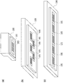
図1は、本発明を適用可能な各種液体吐出ヘッド100および記録素子基板101を示した図である。図1(a)は、記録素子基板101が液体吐出ヘッド100に単独で配置された実施例を示す。本実施例において、液体吐出ヘッド100は、記録媒体に対して主走査方向の往復移動を繰り返しながら記録を行う走査型の液体吐出ヘッドである。図1(b)は、複数の記録素子基板101が液体吐出ヘッド100に千鳥状に配置された実施例を示す。このような液体吐出ヘッド100は、いわゆるラインヘッド形態の液体吐出ヘッドであり、固定された液体吐出ヘッド100に対して記録媒体が移動することにより記録を行う。図1(c)は、複数の記録素子基板101が隣接して配置された実施例を示す。図1(b)と同様に、液体吐出ヘッド100はラインヘッド形態の液体吐出ヘッドであり、固定された液体吐出ヘッド100に対して記録媒体が移動することにより記録を行う。本実施形態における液体吐出ヘッド100は、図1(a)〜(c)に例示される実施形態を含む任意の形態で実施可能であり、これらに限定されるものではない。
(Overall configuration of liquid ejection head)
FIG. 1 is a diagram showing various
(インク供給経路の説明)
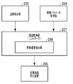
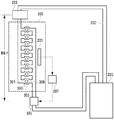
図2は、本実施形態の液体吐出ヘッド100を備える液体吐出装置1において、インク供給経路を示す模式図である。また、図3は、本実施形態の液体吐出装置1のソフトウェア機能ブロック図である。以下、図2および図3を参照し、本実施形態について説明する。
(Description of ink supply path)
FIG. 2 is a schematic diagram illustrating an ink supply path in the liquid ejection device 1 including the
本実施形態において、インクはインクタンク201からインク供給流路202を通り、液体吐出ヘッド100に供給される。液体吐出ヘッド100に供給されたインクの一部は、吐出口303から吐出され記録媒体に付与され、インクの一部は再びインクタンク201に回収される。インク供給流路202には、液体吐出ヘッド100の上流側に負圧調整装置203が設けられ、液体吐出ヘッド100の下流側に循環流発生装置204が設けられている。負圧調整装置203および循環流発生装置204が、インクタンク201と液体吐出ヘッド100の間でインクの循環流を発生させつつ、吐出口303の近傍部分におけるインク圧力を調整することができる。
In the present embodiment, ink is supplied from the
液体吐出ヘッド100には、液体温度であるインクの温度を検知する温度検知部205が内蔵される。本実施形態において、温度検知部205は、インクの温度を直接的または間接的に検知する機構であり、たとえば液体の温度を検知するための温度検知素子によって実現される。温度検知素子をヘッド基板に設け、ヘッド基板の温度を測定することでインクの温度を間接的に測定しても良い。また測定したヘッド基板の温度を後述する制御に用いても良い。本実施形態に適用することができる温度検知素子の例としては、液体吐出ヘッド100に内蔵される抵抗膜型やダイオード型の温度検知センサが挙げられる。その他、温度検知部205は、液体吐出ヘッド100の外部に取り付けられる温度計や、温度検知機能および温度調節機能を備えるサーモスタットなど、さまざまな温度検知機構によって実現することができる。
The
液体吐出装置1には、液体吐出装置1の設置位置における温度および/または湿度の値である環境パラメータ値を取得する環境パラメータ取得部206が設けられる。本実施形態に適用することができる環境パラメータ取得部206の具体的な例としては、一般的な温度計、湿度計のほか、タッチスクリーンディスプレイ上に表示されるユーザインタフェースなどであってもよい。この場合、液体吐出装置1の設置空間において、空調によって一定に保たれた環境温度や環境湿度などのパラメータ値の入力を受け付けることができる。なお、本明細書における「環境温度」「環境湿度」とは、温度検知部205によって検知される温度とは異なる位置における温度値や湿度値であることを意味している。そのため、環境パラメータ取得部206は、温度検知部205と物理的に異なる位置に設けられていればよく、例えば液体吐出装置1の筐体内に設けられていてもよいし、USBケーブルなどを介して液体吐出装置1と外部接続されていてもよい。
The liquid ejection device 1 is provided with an environment
温度検知部205によって検知されたインク温度と、環境パラメータ取得部206によって取得された環境温度および環境湿度とは、流速制御部207に入力される。本実施形態に適用することができる流速制御部207の例としては、液体吐出装置1に搭載され、CPU・メモリなどが一体構成されているMPUなどのコントローラが挙げられる。流速制御部207は、入力を受け付けたインク温度と、環境温度および環境湿度とに基づいてインクの蒸発速度に関する情報を導出する。次いで、流速制御部207は、吐出口303の近傍を通過するインクの流速が最適な値となるように循環流発生装置204を制御する。また、このようなインクの蒸発速度の導出は、蒸発速度導出部208の機能ブロックの処理によって実行される。蒸発速度導出処理については後述する。本実施形態においては環境温度と環境湿度との双方の値に基づきインクの蒸発速度に関する情報を導出しているが、本発明おいては環境温度と環境湿度の少なくとも一方の値に基づいてインクの蒸発速度に関する情報を導出すれば良い。
The ink temperature detected by the
循環流発生装置204は、インクの流れを発生させつつ、インクの流速や流量を所定の値に制御可能な任意の装置によって実現される。具体的には、循環流発生装置204は、定圧力ポンプや定流量ポンプのほか、微細加工技術であるMEMSによって生成され、記録素子基板101に組み込まれたマイクロポンプなどによっても実現することができる。さらには、循環流発生装置204は、液体吐出ヘッド100と一体化して構成してもよく、あるいは、液体吐出ヘッド100の外部に配置され、インク供給チューブを介して液体吐出ヘッド100と接続することもできる。
The circulating
(記録素子基板の構成)
図4(a)は、本実施形態において、液体吐出ヘッド100に搭載される記録素子基板101の外観斜視図である。本実施形態の記録素子基板101は、図4(a)に示される通り、ヘッド基板301上にオリフィスプレート302が接合されており、オリフィスプレート302には複数の吐出口303が配置されている。吐出口303は、複数配列して吐出口列304を構成している。ヘッド基板301は、加工可能な半導体基板などの素材によって形成されることが望ましく、このような素材を用いることにより、ヘッド基板301の表面にエネルギー発生素子や電気回路、電気配線、温度センサ等の電子デバイスが複数配置可能となる。吐出口を複数有する吐出口形成部材であるオリフィスプレート302は、レーザー加工により吐出口303を形成可能な樹脂基板、ダイシングにより吐出口303を形成可能な無機プレートなどの素材によって形成され得る。またオリフィスプレート302は、光硬化により吐出口303およびインク流路を形成する感光樹脂材料などの素材によっても形成され得る。また、ヘッド基板301と同様に半導体基板を用いて、MEMS加工により吐出口303およびインク流路を形成するなど、任意の材料を用いることができる。
(Configuration of printing element substrate)
FIG. 4A is an external perspective view of the
図4(b)は、記録素子基板101をZ軸方向からオリフィスプレート302を見た拡大透視図である。ヘッド基板301とオリフィスプレート302とによって囲まれた空間は圧力室305を構成する。吐出口303は、液体を吐出するために利用されるエネルギーを発生するエネルギー発生素子306に対向する位置に設けられ、インク液滴は吐出口303を介して液体吐出ヘッド100の外部に吐出される。エネルギー発生素子306には、インクを発熱により沸騰させ、インク液滴を液体吐出ヘッド100の外部に吐出する抵抗発熱素子や、圧電効果によりインク液滴を液体吐出ヘッド100の外部に吐出する圧電素子などを用いることができる。圧力室305は、ヘッド基板301とオリフィスプレート302とから構成され、液体流入流路307と液体回収流路308とに流体的に接続する液体流路を構成している。さらに、圧力室305には、エネルギー発生素子306と吐出口303とをそれぞれ少なくとも一つ有する。液体吐出ヘッド100に流入したインクは、インクの供給流路である液体流入流路307から圧力室305を通過してインクの回収流路である液体回収流路308に向かう方向に流れる。
FIG. 4B is an enlarged perspective view of the
図4(c)は、図4(b)の記録素子基板101において、線分IVC−IVCで切断した断面図である。垂直供給口309と、垂直回収口310とはヘッド基板301を貫通し、それぞれ液体流入流路307と、液体回収流路308とに接続する。
FIG. 4C is a cross-sectional view of the
図4(d)は、図4(c)の記録素子基板101において、吐出口303の近傍を拡大した断面図である。図4(d)において、オリフィスプレート302の厚みは符号Do、液体流入流路307(液体回収流路308)の高さは符号Dhに、吐出口303の口径は符号Dwとしてそれぞれ図示される。図4(c)(d)に示される通り、温度検知部205は、ヘッド基板301上の吐出口列304に隣接する領域に配置され、液体流入流路307または液体回収流路308(以下、単に「液体流路」と記す場合がある)内のインク温度を検知する。検知されたインク温度は流速制御部207へ出力される。
FIG. 4D is an enlarged cross-sectional view of the vicinity of the
図2で説明した循環流発生装置204によるインクの流れによって、圧力室305内のインクは圧力室305の外部との間で循環される。具体的には、液体吐出ヘッドの外部から液体吐出ヘッドに流入したインクは、垂直供給口309、液体流入流路307、圧力室305、液体回収流路308、垂直回収口の順に流れ液体吐出ヘッドの外部に導出された後に、再び液体吐出ヘッドに導入される循環経路となる。流速制御部207は、循環流発生装置204が出力するインク流の流速または流量などの出力を変化させることにより、吐出口303の近傍を流れるインクの流速(以下、単に「流速」と記す場合がある)を制御する。本実施形態においては、温度検知部205によって検知される対象は、吐出口303から吐出される直前のインクであることが望ましい。具体的には、温度検知部205の設置個所は、吐出口303の直下や、吐出口303に隣接する位置、または図4(a)のように2以上の吐出口列304が配置されている記録素子基板101場合、吐出口列304の中間位置などが例示される。その他、温度検知部205をインク供給流路202の近傍や記録素子基板101の近傍に設置し、熱伝導手法を用いてインク温度を推測する方法などのように、間接的にインク温度を検知する手法も本実施形態に適用することができる。したがって、温度検知部205の配置位置は図4(c)(d)に示された位置に限定されるものではない。
The ink in the
(インク流速制御のメカニズム)
いわゆるインク循環型の記録ヘッドを搭載する液体吐出装置において、インク温度(もしくは液体吐出ヘッドの温度)が高いときは、インク温度が低いときと比較して、インク増粘の抑制に要するインク流速が早くなる。この理由について、以下簡潔に説明する。
(Ink flow control mechanism)
In a liquid ejection apparatus equipped with a so-called ink circulation type recording head, when the ink temperature (or the temperature of the liquid ejection head) is high, the ink flow rate required for suppressing the ink thickening is lower than when the ink temperature is low. Be faster. The reason is briefly described below.
液体吐出装置におけるインク粘度の増加・減少を検討すると、液体吐出ヘッドにおいて連続的にインクが吐出されている場合、吐出口へのインクの供給も連続的に行われるため、インク粘度の上昇は発生しない、もしくは非常に軽微である。しかし、液体吐出ヘッドがインク吐出を長時間停止する非吐出時に、インクに含まれる溶媒の揮発成分が吐出口から蒸発してしまうため、不揮発性溶剤や色材が濃縮し、吐出口及び圧力室内のインク粘度が上昇する。圧力室内におけるインク粘度の上昇は、吐出口からのインク吐出速度の低下や、吐出口からのインク不吐出などの原因となる。さらには、不揮発性溶剤や色材が濃縮することにより、出力画像に濃度ムラが発生するなどの原因となる。 Considering the increase / decrease in ink viscosity in the liquid ejection device, when ink is continuously ejected from the liquid ejection head, ink supply to the ejection port is also performed continuously, so an increase in ink viscosity occurs. No, or very minor. However, when the liquid discharge head stops the ink discharge for a long time during non-discharge, the volatile components of the solvent contained in the ink evaporate from the discharge ports, so that the non-volatile solvent and the coloring material are concentrated and the discharge ports and the pressure chambers are concentrated. Ink viscosity increases. An increase in the viscosity of the ink in the pressure chamber causes a decrease in the ink ejection speed from the ejection port, a failure to eject the ink from the ejection port, and the like. Furthermore, the concentration of the non-volatile solvent and the coloring material causes unevenness in the density of the output image.
そこで、いわゆる循環型の記録ヘッドでは、圧力室を通過するインク流れを発生させることにより、吐出口や圧力室内で粘度が上昇したインクを回収する手法が知られている。このような循環型の記録ヘッドは、不揮発性溶剤や色材の濃度を略一定に保つことができるため、インクの吐出が長時間停止した場合であっても正常なインク吐出を行うことができる。より詳細には、インク吐出が停止している場合、吐出口から蒸発して失われてしまうインク溶媒の揮発成分量と、循環流により補われるインク量とは平衡状態にある。このとき、圧力室内におけるインクの平均濃縮度は、インク循環流速とインク溶媒の揮発成分の蒸発速度とに依存する。したがって、インク温度が上昇し、インク蒸発速度が増加した場合、圧力室内のインク平均濃縮度を一定に保つためには、インク循環流速をインク蒸発速度に応じて(好ましくは比例して)増加させる必要がある。 Therefore, in a so-called circulation type recording head, there is known a method of recovering ink whose viscosity has increased in an ejection port or a pressure chamber by generating an ink flow passing through a pressure chamber. Such a circulating recording head can maintain the concentration of the non-volatile solvent or the coloring material substantially constant, so that normal ink ejection can be performed even when ink ejection is stopped for a long time. . More specifically, when the ink discharge is stopped, the amount of the volatile component of the ink solvent which is evaporated and lost from the discharge port and the amount of the ink supplemented by the circulation flow are in an equilibrium state. At this time, the average concentration of the ink in the pressure chamber depends on the ink circulation flow rate and the evaporation rate of the volatile components of the ink solvent. Therefore, when the ink temperature increases and the ink evaporation rate increases, the ink circulation flow rate is increased in accordance with (preferably in proportion to) the ink evaporation rate in order to keep the average ink concentration in the pressure chamber constant. There is a need.
図5は、インク溶媒における揮発成分の蒸発速度Jvと、インク循環流速の最小値Jminとの関係を示したグラフである。なお、図5のグラフは、インク溶媒における揮発成分が「水」である例を示している。また、インク循環流速の最小値Jminは、インク吐出が10秒間停止した後にインク吐出が再開された場合の吐出速度と、インク吐出が連続して行われた場合の吐出速度との差が10%以内である例を示している。 FIG. 5 is a graph showing the relationship between the evaporation rate Jv of volatile components in the ink solvent and the minimum value Jmin of the ink circulation flow rate. The graph in FIG. 5 shows an example in which the volatile component in the ink solvent is “water”. In addition, the minimum value Jmin of the ink circulation flow rate is 10% of the difference between the ejection speed when the ink ejection is restarted after the ink ejection is stopped for 10 seconds and the ejection speed when the ink ejection is continuously performed. FIG.
図5に示されるグラフにおいて、液体吐出ヘッドIにおけるオリフィスプレートの厚みDoは8μm、液体流路の高さDhは6μm、吐出口の口径Dwは19.5μmである。一方、液体吐出ヘッドIIのオリフィスプレートの厚みDoは6μm、液体流路の高さDhは6μm、吐出口の口径Dwは17μmである。液体吐出ヘッドI、II共に、蒸発速度Jvと、インクを正常に吐出するために必要な最低循環流速Jminとは略比例関係にある。 In the graph shown in FIG. 5, the thickness Do of the orifice plate in the liquid discharge head I is 8 μm, the height Dh of the liquid flow path is 6 μm, and the diameter Dw of the discharge port is 19.5 μm. On the other hand, the thickness Do of the orifice plate of the liquid discharge head II is 6 μm, the height Dh of the liquid flow path is 6 μm, and the diameter Dw of the discharge port is 17 μm. In both of the liquid ejection heads I and II, the evaporation speed Jv and the minimum circulation flow rate Jmin required for normal ink ejection are in a substantially proportional relationship.
ここで、蒸発速度Jvと最低循環流速Jminとの比を、比例定数Jmin/Jvとした場合、比例定数Jmin/Jvの値は液体吐出ヘッド100の構成とインクの組成とに依存する。
Here, assuming that the ratio between the evaporation rate Jv and the minimum circulation flow rate Jmin is a proportional constant Jmin / Jv, the value of the proportional constant Jmin / Jv depends on the configuration of the
図6は、オリフィスプレートの厚みDo、液体流路の高さDh、吐出口の口径Dwの組み合わせが異なるいくつかの液体吐出ヘッドと、比例定数Jmin/Jvの値とが対応付けられたテーブルを示す。図6に示される通り、比例定数Jmin/Jvの値は、液体吐出ヘッドの構成によって異なる。出願人が実験を通じて得た結果によれば、比例定数Jmin/Jvの値は、概ね5〜100の範囲となることが判明した。循環流速の変動等のマージンを考慮すると、蒸発速度の10〜200倍の範囲となるように吐出口の近傍を流れる流速を制御することができれば、インク吐出が長時間停止した場合であっても、安定したインク吐出を行うことが可能となることが想定される。 FIG. 6 is a table in which several liquid discharge heads having different combinations of the thickness Do of the orifice plate, the height Dh of the liquid flow path, and the diameter Dw of the discharge port are associated with the values of the proportionality constant Jmin / Jv. Show. As shown in FIG. 6, the value of the proportional constant Jmin / Jv differs depending on the configuration of the liquid ejection head. According to the results obtained by the applicant through experiments, it has been found that the value of the proportionality constant Jmin / Jv is generally in the range of 5 to 100. In consideration of margins such as fluctuations in the circulation flow rate, if the flow rate near the discharge port can be controlled so as to be in the range of 10 to 200 times the evaporation rate, even if the ink discharge is stopped for a long time, It is assumed that stable ink ejection can be performed.
(蒸発速度の導出手法)
以上説明した通り、インク吐出が長時間停止した場合であっても、安定したインク吐出を実現するために好適な循環流速は、インクの蒸発速度に比例する。
ここで、インク蒸発速度Jv[mm/s]は、インク温度T[℃]、環境温度T0[℃]、環境湿度をH[%]としたとき、次式で求めることができる。
Jv = K×(Pv(T)−Pv(T0)×H/100) ・・(式1)
ここで、Pv(T)[mmHg]は、温度Tにおけるインク溶媒の飽和蒸気圧であり、インク溶媒が主に水である場合、次の経験式(Antoineの式)で表される。
log Pv(T)=8.03−1706/(T+231.4) ・・(式2)
(Method of deriving evaporation rate)
As described above, even when the ink ejection is stopped for a long time, the circulation flow rate suitable for achieving stable ink ejection is proportional to the ink evaporation rate.
Here, the ink evaporation speed Jv [mm / s] can be obtained by the following equation, where the ink temperature is T [° C.], the environmental temperature is T0 [° C.], and the environmental humidity is H [%].
Jv = K × (Pv (T) −Pv (T0) × H / 100) (Equation 1)
Here, Pv (T) [mmHg] is the saturated vapor pressure of the ink solvent at the temperature T, and is expressed by the following empirical formula (Antoine's formula) when the ink solvent is mainly water.
log Pv (T) = 8.03-1706 / (T + 231.4) (formula 2)
式1における比例係数Kは、吐出口近傍から蒸発したインク溶媒の飽和蒸気が広がっている領域の厚み(境膜厚)に基づく定数である。比例係数Kの値は、主に吐出口の開口面積に応じて決まり、実験値に基づいて定めることができる。開口面積が250平方μmの吐出口を有する液体吐出ヘッドでは、K=0.013程度となる。 The proportional coefficient K in Equation 1 is a constant based on the thickness (boundary film thickness) of the region where the saturated vapor of the ink solvent evaporated from the vicinity of the ejection port spreads. The value of the proportional coefficient K is determined mainly according to the opening area of the discharge port, and can be determined based on an experimental value. In a liquid ejection head having an ejection opening having an opening area of 250 square μm, K is about 0.013.
本実施形態の蒸発速度導出部208は、温度検知部205により検知されたインク温度(ヘッド温度)Tと、環境パラメータ取得部206により取得された環境温度T0および環境湿度Hとから、上記数式1および数式2を用いて、蒸発速度Jvを算出することができる。なお、実施形態は、蒸発速度導出部208が、上記数式1および数式2を用いて蒸発速度Jvを算出する態様に限定されない。例えば、インク温度Tと、環境温度T0と、環境湿度Hと組み合わせによって定められるインクの蒸発速度Jvを測定し、入力値に応じた蒸発速度Jvを参照可能なテーブルJv(T,T0,H)として流速制御部207の記憶領域に保持されていてもよい。この場合、蒸発速度導出部208は、インク温度T、環境温度T0、環境湿度Hなどの値と、テーブルJv(T,T0,H)とに基づいて、蒸発速度Jvを導出することができる。また環境パラメータ取得部においては、環境温度と環境湿度の双方でなく、いずれか一方の値から蒸発速度を算出しても良い。
The evaporation
(具体例)
上記説明した実施形態について、具体例を示して以下説明する。オリフィスプレートの厚み(Do)が11μm、流路高さ(Dh)が14μm、吐出口の口径(Dw)が50平方μm(開口面積が250平方μm)構成の液体吐出ヘッドについて、上記具体値に基づいた循環流速の設計値を以下に説明する。インク温度T=55℃、環境温度T0=25℃、湿度50%とした場合、開口面積250平方μmの吐出口から、純水が蒸発する蒸発速度Jvは0.27mm/sとなる。そこで、蒸発速度導出部208は、インクの循環流速Jが蒸発速度Jvの10〜200倍の値となるように循環流速Jを可変させる。すなわち、循環流速Jを5.0mm/s〜27mm/sの範囲の値となるように循環流量を制御することができれば、安定したインク吐出が実現される。
(Concrete example)
The above-described embodiment will be described below with reference to a specific example. For the liquid discharge head having a configuration in which the thickness (Do) of the orifice plate is 11 μm, the flow path height (Dh) is 14 μm, and the diameter of the discharge port (Dw) is 50 square μm (the opening area is 250 square μm), The design value of the circulation flow rate based on this will be described below. When the ink temperature T is 55 ° C., the environmental temperature T0 is 25 ° C., and the humidity is 50%, the evaporation speed Jv at which pure water evaporates from a discharge port having an opening area of 250 μm is 0.27 mm / s. Therefore, the evaporation
また、インク温度T=30℃の場合、蒸発速度Jvは0.03mm/sとなる。この場合、循環流速Jを0.6mm/s〜3.0mm/sの範囲の値となるように循環流量を制御することができれば、安定したインク吐出が実現される。また、インク温度T=80℃の場合、蒸発速度Jvは0.6mm/sとなる。この場合、循環流速Jを6〜120mm/sの範囲の値となるよう循環流量を制御することができれば、安定したインク吐出が実現される。水などの揮発性溶媒をインクに適用する場合、液体吐出装置における許容動作温度は80℃以下が妥当であり、本実施形態による循環流速Jは、0.5mm/s以上(インク低温時)〜120mm/s以下(インク高温時)の範囲内の値となる。 When the ink temperature T is 30 ° C., the evaporation speed Jv is 0.03 mm / s. In this case, if the circulating flow rate can be controlled so that the circulating flow velocity J becomes a value in the range of 0.6 mm / s to 3.0 mm / s, stable ink ejection is realized. When the ink temperature T is 80 ° C., the evaporation speed Jv is 0.6 mm / s. In this case, if the circulating flow rate can be controlled so that the circulating flow rate J becomes a value in the range of 6 to 120 mm / s, stable ink ejection is realized. When a volatile solvent such as water is applied to the ink, the allowable operating temperature of the liquid ejecting apparatus is appropriately 80 ° C. or less, and the circulation flow rate J according to the present embodiment is 0.5 mm / s or more (at the time of low ink temperature). The value is within a range of 120 mm / s or less (at the time of high temperature of the ink).
以上説明した通り、本実施形態の液体吐出装置は、吐出口からのインク蒸発速度と、安定したインク吐出に要する最低循環流速とが略比例関係となる点に着目し、検出されたインク温度などに基づいて圧力室を通過するインクの流量を制御する。かかる構成により、本実施形態の液体吐出装置は、インク温度が変動しても、当該インク温度に応じた最低循環流速でインクを循環させることにより、インク増粘やインク増粘によって引き起こされる画質低下を抑制することができる。 As described above, the liquid ejecting apparatus according to the present embodiment focuses on the point that the ink evaporation rate from the ejection port and the minimum circulation flow rate required for stable ink ejection are substantially proportional to each other. And controls the flow rate of ink passing through the pressure chamber. With such a configuration, even when the ink temperature fluctuates, the ink is circulated at the minimum circulation flow rate according to the ink temperature, thereby reducing the image quality caused by the ink thickening or the ink thickening. Can be suppressed.
[実施形態2]
図7は、実施形態2の液体吐出ヘッド100を備える液体吐出装置1において、インク供給経路を示す模式図である。以下、図7を参照して実施形態2について説明する。上述の実施形態1では、液体吐出ヘッド100内を循環するインク温度は、主にエネルギー発生素子306から受ける熱と、記録素子基板101に設けられた回路から受ける熱と、インク供給経路における熱交換とにより、受動的に決まっていた。しかし、液体吐出装置1が高速出力を行う際、インクを吐出する周期である吐出周波数が高くなるとインク温度の変化が大きくなる。この結果、駆動されるエネルギー発生素子の密度が高い領域と低い領域との間でインク温度差が大きくなり、結果として吐出されるインク液滴の体積に差が生じてしまう。これは、出力物の濃度ムラの原因となるため、これを解消するためには、駆動されるエネルギー発生素子の密度に関わらず、インク温度を一定に保つ仕組みが必要となる。本実施形態の液体吐出ヘッド100は、エネルギー発生素子306とは異なる温度調節素子402を備え、温度検知部205との間でインク温度のフィードバック制御を行うことにより、インク温度を予め設定された範囲の値に保つことができる。本実施形態の液体吐出装置1は、環境温度(環境湿度)や出力速度などによって最適なインク温度が異なるため、インク温度の設定値は所定範囲内の温度に設定可能であることが望ましい。
[Embodiment 2]
FIG. 7 is a schematic diagram illustrating an ink supply path in the liquid ejection apparatus 1 including the
図7は、本実施形態のインク供給経路の具体的構成を示す模式図である。本実施形態の液体吐出装置1は、実施形態1の温度検知部205、環境パラメータ取得部206、流速制御部207に加えて、温度制御部401および温度調節素子402を備えることを特徴とする。温度制御部401は、温度検知部205で検知されたインク温度が設定温度を超過した場合、温度調節素子402を停止してインク温度を低下させる。一方、温度制御部401は、温度検知部205で検知されたインク温度が設定温度よりも低下した場合、温度調節素子402を駆動してインク温度を上昇させる。流速制御部207は、実施形態1と同様に、温度検知部205により検知されたインク温度および環境パラメータ取得部206により取得された環境温度、環境湿度により、蒸発速度を導出する。次いで、流速制御部207は、圧力室305を通過するインクの流速を、蒸発速度の10〜200倍となるように、循環流発生装置204の出力を制御する。
FIG. 7 is a schematic diagram illustrating a specific configuration of the ink supply path according to the present embodiment. The liquid ejection apparatus 1 of the present embodiment is characterized by including a
以上説明した通り、本実施形態の液体吐出装置は、温度制御部401および温度調節素子402を備え、液体吐出ヘッド100内を循環するインク温度を予め設定された一定の設定温度に保つ。かかる構成により、吐出されるインク液滴の体積を一定に保ち、出力物の濃度ムラを防ぎつつ、最小限のインク循環流速で吐出口近傍のインク増粘を抑制することができる。
As described above, the liquid ejection apparatus of the present embodiment includes the
[実施形態3]
図8は、実施形態3の液体吐出ヘッド100を備える液体吐出装置1において、インク供給経路を示す模式図である。以下、図8を参照して実施形態3について説明する。上述の実施形態1〜2において、液体吐出装置1のインク供給経路を循環するインクの流速は循環流発生装置204によって制御される例について説明した。本実施形態では、液体吐出ヘッド100の上流側に負圧調整装置203を、液体吐出ヘッド100の下流側に定圧力ポンプ501を設けた一対の圧力調整機構を適用した場合の望ましい構成例について以下説明する。
[Embodiment 3]
FIG. 8 is a schematic diagram illustrating an ink supply path in the liquid ejection apparatus 1 including the
循環流発生装置に定圧力ポンプ501を適用した場合、圧力室305を通過するインクの流速は、負圧調整装置203と定圧力ポンプ501との間に印加される差圧P、インクの粘度ηおよび液体吐出装置1における全インク供給路の流路抵抗によって決まる。ここで、全インク供給路とは、インクタンク201、インク供給流路202、液体流入流路307、圧力室305、液体回収流路308、インク供給流路202から再びインクタンク201に戻る循環流路全体をいう。また、流路抵抗とは、ある流路の両端に差圧Pを印加したときに生じる流量をQ、流路内の流体の粘度をηとしたときに、R=P/Q/ηで表される係数である。
When the
インク粘度はインク温度に依存するため、温度検知部205により検知された温度Tから、あらかじめ粘度計により求めた温度特性カーブη(T)を用いて算出しておく必要がある。圧力室305を通過するインクの流速は差圧に比例し粘度に反比例する。従って、本実施形態の液体吐出装置1では、定圧力ポンプ501によって印加される差圧Pを、蒸発速度Jvおよびインク粘度ηに比例させる。すなわち、負圧調整装置203と定圧力ポンプ501とが、P/Jv(T)/η(T)の値が一定となるように制御することができれば、吐出口近傍の増粘を抑制する最低限の流速で好適な吐出を実現することができる。定圧力ポンプ501の印加圧力P[Pa],インク粘度をη[Pa・s],全インク供給路の抵抗をR[mm]、圧力室305において液体が流れる方向である流方向に鉛直な面の流路断面積をA[mm^2]とする。このとき、圧力室305内のインク流速Jは、J=P/(η×R×A)で求められる。以上説明した通り、上記値および上記値を用いる計算式によって、J/Jv=P/(η×R×A×Jv)=10〜200の範囲になるように圧力Pを制御することにより、吐出口近傍の増粘を抑制する最低限の流速で好適な吐出を実現することができる。
Since the ink viscosity depends on the ink temperature, it needs to be calculated from the temperature T detected by the
以上説明した通り、本実施形態の液体吐出装置は、定圧力ポンプ501を備え、負圧調整装置203と定圧力ポンプ501とを用いて液体吐出装置1内のインク循環を行う。かかる構成により、液体吐出ヘッド100内におけるインク温度の変動にかかわらず、最小限のインク循環流速で吐出口近傍のインク増粘を抑制することができる。
As described above, the liquid ejection device of the present embodiment includes the
[その他の実施例]
本発明は、上述の実施形態の1以上の機能を実現するプログラムを、ネットワーク又は記憶媒体を介してシステム又は装置に供給し、そのシステム又は装置のコンピュータにおける1つ以上のプロセッサーがプログラムを読出し実行する処理でも実現可能である。また、1以上の機能を実現する回路(例えば、ASIC)によっても実現可能である。
[Other Examples]
The present invention supplies a program for realizing one or more functions of the above-described embodiments to a system or an apparatus via a network or a storage medium, and one or more processors in a computer of the system or the apparatus read and execute the program. This processing can be realized. Further, it can also be realized by a circuit (for example, an ASIC) that realizes one or more functions.
100・・液体吐出ヘッド
101・・記録素子基板
205・・温度検知部
206・・環境パラメータ取得部
207・・流速制御部
208・・蒸発速度導出部
301・・ヘッド基板
302・・オリフィスプレート
303・・吐出口
305・・圧力室
306・・エネルギー発生素子
307・・液体流入流路
308・・液体回収流路
100
Claims (15)
前記エネルギー発生素子に対向する位置に設けられる吐出口と、
前記エネルギー発生素子が複数配置されるヘッド基板と、
前記吐出口を複数有する吐出口形成部材と、
前記ヘッド基板と前記吐出口形成部材とから構成され、前記エネルギー発生素子を備える圧力室と、
前記圧力室への液体の供給流路である液体流入流路と、
前記圧力室からの液体の回収流路である液体回収流路と、
から構成される液体吐出ヘッドを備える液体吐出装置であって、
前記吐出口から液体が吐出していない非吐出時に、前記吐出口から液体に含まれる揮発成分が蒸発する速度である蒸発速度に関する情報を取得する取得手段と、
前記取得手段によって取得された前記蒸発速度に関する情報に基づいて、前記液体流入流路から前記圧力室を通過して前記液体回収流路に向かう方向に生じる液体の流速を制御する流速制御手段とを備え、
前記流速制御手段は、前記蒸発速度が高いほど、前記圧力室を通過する液体の流速が早くなるように制御可能であることを特徴とする
液体吐出装置。 An energy generating element for generating energy for discharging the liquid,
An ejection port provided at a position facing the energy generating element,
A head substrate on which a plurality of the energy generating elements are arranged,
A discharge port forming member having a plurality of the discharge ports,
A pressure chamber including the head substrate and the discharge port forming member, and including the energy generating element;
A liquid inflow path that is a supply path of the liquid to the pressure chamber,
A liquid recovery flow path that is a recovery flow path for liquid from the pressure chamber,
A liquid ejection device including a liquid ejection head composed of:
Acquisition means for acquiring information about an evaporation rate, which is a rate at which volatile components contained in liquid evaporate from the ejection port during non-ejection when liquid is not ejected from the ejection port,
Flow rate control means for controlling a flow rate of a liquid generated in a direction from the liquid inflow path to the liquid recovery flow path through the pressure chamber based on the information on the evaporation rate acquired by the acquisition means. Prepared ,
The liquid discharge device , wherein the flow rate control means can control the flow rate of the liquid passing through the pressure chamber to increase as the evaporation rate increases .
ことを特徴とする請求項1に記載の液体吐出装置。 The liquid ejection device according to claim 1, wherein the liquid passing through the pressure chamber is circulated between the liquid and the outside of the pressure chamber.
前記吐出口から液体が吐出していない非吐出時において、前記圧力室を通過する液体の流速をJ、前記蒸発速度をJvとしたとき、
10<J/Jv<200
を満たすように前記圧力室を通過する液体の流速を制御する
ことを特徴とする請求項1または2に記載の液体吐出装置。 The flow velocity control means,
At the time of non-discharge when liquid is not discharged from the discharge port, when the flow velocity of the liquid passing through the pressure chamber is J and the evaporation rate is Jv,
10 <J / Jv <200
The liquid discharge device according to claim 1 , wherein the flow rate of the liquid passing through the pressure chamber is controlled so as to satisfy the following condition.
前記吐出口から液体が吐出していない非吐出時において、前記圧力室を通過する液体の流速を0.5mm/s以上かつ120mm/s以下に制御する
ことを特徴とする請求項1から3のいずれか1項に記載の液体吐出装置。 The flow velocity control means,
4. The flow rate of the liquid passing through the pressure chamber is controlled to be 0.5 mm / s or more and 120 mm / s or less when the liquid is not being discharged from the discharge port at the time of non-discharge. 5. apparatus according to any one of claims.
前記温度検知手段によって検知された液体温度に基づいて前記蒸発速度を導出する蒸発速度導出手段とをさらに備える
ことを特徴とする請求項1から4のいずれか1項に記載の液体吐出装置。 Temperature detection means for detecting a liquid temperature;
The liquid ejection apparatus according to claim 1 , further comprising: an evaporation speed deriving unit that derives the evaporation speed based on the liquid temperature detected by the temperature detection unit.
前記蒸発速度導出手段は、
前記温度検知手段によって検知された液体温度と、環境パラメータ取得手段によって取得された環境パラメータ値とに基づいて前記蒸発速度を導出する
ことを特徴とする請求項5に記載の液体吐出装置。 Further provided is an environmental parameter obtaining means for obtaining an environmental parameter at the installation position of the liquid ejection device,
The evaporation rate deriving means,
The liquid ejection device according to claim 5 , wherein the evaporation rate is derived based on a liquid temperature detected by the temperature detection unit and an environment parameter value acquired by an environment parameter acquisition unit.
ことを特徴とする請求項6に記載の液体吐出装置。 The liquid discharge device according to claim 6 , wherein the environmental parameter value is a value indicating an environmental temperature and an environmental humidity at an installation position of the liquid discharge device.
前記液体温度がT(℃)、前記環境温度がT0(℃)、前記環境湿度がH(%)となる場合における前記蒸発速度であるJv(mm/s)を、
Jv = 0.01×(Pv(T)−Pv(T0)×H/100)
log Pv(T)=8.03−1706/(T+231.4)
により算出する
ことを特徴とする請求項7に記載の液体吐出装置。 The evaporation rate deriving means,
Jv (mm / s), which is the evaporation rate when the liquid temperature is T (° C.), the environmental temperature is T 0 (° C.), and the environmental humidity is H (%),
Jv = 0.01 × (Pv (T) −Pv (T0) × H / 100)
log Pv (T) = 8.03-1706 / (T + 231.4)
The liquid ejection device according to claim 7 , wherein the calculation is performed by:
前記液体温度、前記環境温度、前記環境湿度の組み合わせと、前記蒸発速度とが対応付けられたテーブルを保持し、当該テーブルを参照することにより前記蒸発速度を導出する
ことを特徴とする請求項7に記載の液体吐出装置。 The evaporation rate deriving means,
8. A table in which a combination of the liquid temperature, the environmental temperature, and the environmental humidity is associated with the evaporation rate, and the evaporation rate is derived by referring to the table. 9. A liquid ejection device according to claim 1.
液体温度を所定範囲内の温度となるように前記温度調節素子を制御する温度制御手段とをさらに備える
ことを特徴とする請求項1から9のいずれか1項に記載の液体吐出装置。 A temperature adjusting element different from the energy generating element,
The liquid ejecting apparatus according to claim 1 , further comprising: a temperature control unit configured to control the temperature adjusting element so that the liquid temperature falls within a predetermined range.
前記流速制御手段は、
前記吐出口から液体が吐出していない非吐出時において、前記一対の圧力調整機構によって印加される差圧をP、液体の粘度をη、前記液体吐出装置における全てのインク流路の抵抗をR、前記圧力室において液体が流れる方向である流方向に鉛直な面の流路断面積をA、液体に含まれる揮発成分が前記吐出口から蒸発する蒸発速度をJvとしたとき、
10<P/(η×R×A×Jv)<200
を満たすように前記圧力室を通過する液体の流速を制御する
ことを特徴とする請求項1から10のいずれか1項に記載の液体吐出装置。 Further comprising a pair of pressure adjustment mechanisms on the upstream and downstream sides of the liquid ejection head,
The flow velocity control means,
When no liquid is ejected from the ejection port, the differential pressure applied by the pair of pressure adjusting mechanisms is P, the viscosity of the liquid is η, and the resistance of all ink flow paths in the liquid ejection device is R. When the flow path cross-sectional area of a surface perpendicular to the flow direction in which the liquid flows in the pressure chamber is A, and the evaporation rate at which a volatile component contained in the liquid evaporates from the discharge port is Jv,
10 <P / (η × R × A × Jv) <200
The liquid discharge device according to any one of claims 1 to 10 , wherein a flow rate of the liquid passing through the pressure chamber is controlled so as to satisfy the following condition.
前記エネルギー発生素子に対向する位置に設けられる吐出口と、
前記エネルギー発生素子が複数配置されるヘッド基板と、
前記吐出口を複数有する吐出口形成部材と、
前記ヘッド基板と前記吐出口形成部材とから構成され、前記エネルギー発生素子と前記吐出口とをそれぞれ少なくとも一つ有する圧力室と、
前記圧力室への液体の供給流路である液体流入流路と、
前記圧力室からの液体の回収流路である液体回収流路と、
から構成される液体吐出ヘッドを備える液体吐出装置の制御方法であって、
前記吐出口から液体が吐出していない非吐出時に、前記吐出口から液体に含まれる揮発成分が蒸発する速度である蒸発速度に関する情報を取得する取得ステップと、
前記取得ステップにおいて取得された前記蒸発速度に関する情報に基づいて、前記液体流入流路から前記圧力室を通過して前記液体回収流路に向かう方向に生じる液体の流速を制御する流速制御ステップとを備え、
前記流速制御ステップにおいて、前記蒸発速度が高いほど、前記圧力室を通過する液体の流速が早くなるように制御可能であることを特徴とする制御方法。 An energy generating element for generating energy for discharging the liquid,
An ejection port provided at a position facing the energy generating element,
A head substrate on which a plurality of the energy generating elements are arranged,
A discharge port forming member having a plurality of the discharge ports,
A pressure chamber composed of the head substrate and the discharge port forming member, and having at least one each of the energy generating element and the discharge port;
A liquid inflow path that is a supply path of the liquid to the pressure chamber,
A liquid recovery flow path that is a recovery flow path for liquid from the pressure chamber,
A method for controlling a liquid ejection apparatus including a liquid ejection head comprising:
An acquisition step of acquiring information about an evaporation rate that is a rate at which a volatile component contained in the liquid evaporates from the ejection port during non-ejection when the liquid is not ejected from the ejection port;
A flow rate control step of controlling a flow rate of a liquid generated in a direction from the liquid inflow passage to the liquid recovery flow passage through the pressure chamber based on the information on the evaporation speed acquired in the acquisition step. Prepared ,
The control method according to claim 1, wherein in the flow rate control step, the flow rate of the liquid passing through the pressure chamber can be controlled to increase as the evaporation rate increases .
前記エネルギー発生素子に対向する位置に設けられる吐出口と、
前記エネルギー発生素子を備える圧力室と、
前記圧力室への液体の供給流路である液体流入流路と、
前記圧力室からの液体の回収流路である液体回収流路と、
から構成される液体吐出ヘッドを備える液体吐出装置であって、
前記液体流入流路から前記圧力室を通過して前記液体回収流路に向かう方向に生じる液体の流速を制御する流速制御手段を備え、該流速制御手段は、液体に含まれる揮発成分が前記吐出口から蒸発する蒸発速度が高いほど、前記圧力室を通過する液体の流速が早くなるように制御可能であることを特徴とする液体吐出装置。 An energy generating element for generating energy for discharging the liquid,
An ejection port provided at a position facing the energy generating element,
A pressure chamber including the energy generating element,
A liquid inflow path that is a supply path of the liquid to the pressure chamber,
A liquid recovery flow path that is a recovery flow path for liquid from the pressure chamber,
A liquid ejection device including a liquid ejection head composed of:
Flow rate control means for controlling a flow rate of the liquid generated in a direction from the liquid inflow path to the liquid recovery flow path through the pressure chamber, wherein the flow rate control means discharges a volatile component contained in the liquid into the discharge port. A liquid discharge apparatus characterized in that it is possible to control the flow rate of the liquid passing through the pressure chamber to increase as the evaporation rate evaporating from the outlet increases.
ことを特徴とする請求項14に記載の液体吐出装置。 The liquid ejecting apparatus according to claim 14 , wherein the liquid passing through the pressure chamber is circulated between the pressure chamber and the outside.
Priority Applications (1)
| Application Number | Priority Date | Filing Date | Title |
|---|---|---|---|
| JP2016025258A JP6672002B2 (en) | 2016-02-12 | 2016-02-12 | Liquid ejection device and control method |
Applications Claiming Priority (1)
| Application Number | Priority Date | Filing Date | Title |
|---|---|---|---|
| JP2016025258A JP6672002B2 (en) | 2016-02-12 | 2016-02-12 | Liquid ejection device and control method |
Publications (3)
| Publication Number | Publication Date |
|---|---|
| JP2017140807A JP2017140807A (en) | 2017-08-17 |
| JP2017140807A5 JP2017140807A5 (en) | 2019-02-28 |
| JP6672002B2 true JP6672002B2 (en) | 2020-03-25 |
Family
ID=59627614
Family Applications (1)
| Application Number | Title | Priority Date | Filing Date |
|---|---|---|---|
| JP2016025258A Active JP6672002B2 (en) | 2016-02-12 | 2016-02-12 | Liquid ejection device and control method |
Country Status (1)
| Country | Link |
|---|---|
| JP (1) | JP6672002B2 (en) |
Families Citing this family (4)
| Publication number | Priority date | Publication date | Assignee | Title |
|---|---|---|---|---|
| JP7119359B2 (en) * | 2017-11-30 | 2022-08-17 | ブラザー工業株式会社 | Liquid ejector |
| JP7268415B2 (en) * | 2018-03-19 | 2023-05-08 | 株式会社リコー | Liquid ejection unit and liquid ejection device |
| JP7363339B2 (en) * | 2019-10-11 | 2023-10-18 | セイコーエプソン株式会社 | Liquid injection equipment, maintenance method for liquid injection equipment |
| JP7467113B2 (en) * | 2019-12-26 | 2024-04-15 | キヤノン株式会社 | Recording apparatus and control method thereof |
Family Cites Families (7)
| Publication number | Priority date | Publication date | Assignee | Title |
|---|---|---|---|---|
| JP2002234175A (en) * | 2001-02-08 | 2002-08-20 | Canon Inc | Method and apparatus for preventing ink thickening in liquid ejecting apparatus, and color filter manufacturing apparatus |
| US20030142159A1 (en) * | 2002-01-31 | 2003-07-31 | Askeland Ronald A. | Estimating local ejection chamber temperature to improve printhead performance |
| US7597434B2 (en) * | 2006-04-27 | 2009-10-06 | Toshiba Tec Kabushiki Kaisha | Ink-jet apparatus and method of the same |
| JP2009154328A (en) * | 2007-12-25 | 2009-07-16 | Fuji Xerox Co Ltd | Liquid droplet discharge head and image forming apparatus equipped with the same |
| CN103640336B (en) * | 2008-05-23 | 2015-12-02 | 富士胶片株式会社 | Fluid droplet ejecting device |
| JP5805018B2 (en) * | 2011-06-30 | 2015-11-04 | 京セラドキュメントソリューションズ株式会社 | Image forming apparatus |
| JP5978626B2 (en) * | 2012-01-12 | 2016-08-24 | セイコーエプソン株式会社 | Liquid ejector |
-
2016
- 2016-02-12 JP JP2016025258A patent/JP6672002B2/en active Active
Also Published As
| Publication number | Publication date |
|---|---|
| JP2017140807A (en) | 2017-08-17 |
Similar Documents
| Publication | Publication Date | Title |
|---|---|---|
| JP7379633B2 (en) | Liquid circulation device, liquid discharge device | |
| US10471711B2 (en) | Printing apparatus, printing method, and medium | |
| US9975340B2 (en) | Printing apparatus and medium | |
| US10737503B2 (en) | Fluid circulation apparatus and fluid ejection apparatus | |
| JP6672002B2 (en) | Liquid ejection device and control method | |
| US20100309244A1 (en) | Image forming apparatus which adjusts ink temperature | |
| CN111716910B (en) | Liquid supply device and liquid discharge device | |
| JP6719918B2 (en) | Liquid ejection head and liquid ejection device | |
| US10449776B2 (en) | Print head sensing chamber circulation | |
| JP6463034B2 (en) | Liquid discharge head | |
| JP2015157362A (en) | Ink supply system for ink jet printer and ink pressure control method in the same | |
| JP2018043518A (en) | Liquid circulation device, liquid ejection device, and liquid ejection method | |
| JP5502497B2 (en) | Inkjet head and inkjet apparatus | |
| EP3594001B1 (en) | Liquid ejecting head | |
| JP2017144694A (en) | Liquid discharge head and liquid discharge device | |
| JP6702748B2 (en) | Recording device and liquid ejection head | |
| KR20100030148A (en) | Inkjet printhead | |
| JP7650765B2 (en) | Liquid circulating device and liquid ejecting device | |
| JP7472071B2 (en) | Apparatus and method for measuring viscosity of liquid | |
| JP2013028041A (en) | Circulation type inkjet head apparatus |
Legal Events
| Date | Code | Title | Description |
|---|---|---|---|
| A521 | Written amendment |
Free format text: JAPANESE INTERMEDIATE CODE: A523 Effective date: 20190117 |
|
| A621 | Written request for application examination |
Free format text: JAPANESE INTERMEDIATE CODE: A621 Effective date: 20190117 |
|
| A131 | Notification of reasons for refusal |
Free format text: JAPANESE INTERMEDIATE CODE: A131 Effective date: 20191119 |
|
| A977 | Report on retrieval |
Free format text: JAPANESE INTERMEDIATE CODE: A971007 Effective date: 20191120 |
|
| A521 | Written amendment |
Free format text: JAPANESE INTERMEDIATE CODE: A523 Effective date: 20200117 |
|
| TRDD | Decision of grant or rejection written | ||
| A01 | Written decision to grant a patent or to grant a registration (utility model) |
Free format text: JAPANESE INTERMEDIATE CODE: A01 Effective date: 20200204 |
|
| A61 | First payment of annual fees (during grant procedure) |
Free format text: JAPANESE INTERMEDIATE CODE: A61 Effective date: 20200304 |
|
| R151 | Written notification of patent or utility model registration |
Ref document number: 6672002 Country of ref document: JP Free format text: JAPANESE INTERMEDIATE CODE: R151 |