JP6670446B2 - connector - Google Patents
connector Download PDFInfo
- Publication number
- JP6670446B2 JP6670446B2 JP2016118636A JP2016118636A JP6670446B2 JP 6670446 B2 JP6670446 B2 JP 6670446B2 JP 2016118636 A JP2016118636 A JP 2016118636A JP 2016118636 A JP2016118636 A JP 2016118636A JP 6670446 B2 JP6670446 B2 JP 6670446B2
- Authority
- JP
- Japan
- Prior art keywords
- retainer
- housing
- terminal
- locking position
- unit
- Prior art date
- Legal status (The legal status is an assumption and is not a legal conclusion. Google has not performed a legal analysis and makes no representation as to the accuracy of the status listed.)
- Active
Links
Images


Classifications
-
- H—ELECTRICITY
- H01—ELECTRIC ELEMENTS
- H01R—ELECTRICALLY-CONDUCTIVE CONNECTIONS; STRUCTURAL ASSOCIATIONS OF A PLURALITY OF MUTUALLY-INSULATED ELECTRICAL CONNECTING ELEMENTS; COUPLING DEVICES; CURRENT COLLECTORS
- H01R13/00—Details of coupling devices of the kinds covered by groups H01R12/70 or H01R24/00 - H01R33/00
- H01R13/40—Securing contact members in or to a base or case; Insulating of contact members
- H01R13/42—Securing in a demountable manner
-
- H—ELECTRICITY
- H01—ELECTRIC ELEMENTS
- H01R—ELECTRICALLY-CONDUCTIVE CONNECTIONS; STRUCTURAL ASSOCIATIONS OF A PLURALITY OF MUTUALLY-INSULATED ELECTRICAL CONNECTING ELEMENTS; COUPLING DEVICES; CURRENT COLLECTORS
- H01R13/00—Details of coupling devices of the kinds covered by groups H01R12/70 or H01R24/00 - H01R33/00
- H01R13/02—Contact members
- H01R13/20—Pins, blades, or sockets shaped, or provided with separate member, to retain co-operating parts together
-
- H—ELECTRICITY
- H01—ELECTRIC ELEMENTS
- H01R—ELECTRICALLY-CONDUCTIVE CONNECTIONS; STRUCTURAL ASSOCIATIONS OF A PLURALITY OF MUTUALLY-INSULATED ELECTRICAL CONNECTING ELEMENTS; COUPLING DEVICES; CURRENT COLLECTORS
- H01R13/00—Details of coupling devices of the kinds covered by groups H01R12/70 or H01R24/00 - H01R33/00
- H01R13/40—Securing contact members in or to a base or case; Insulating of contact members
- H01R13/42—Securing in a demountable manner
- H01R13/436—Securing a plurality of contact members by one locking piece or operation
- H01R13/4361—Insertion of locking piece perpendicular to direction of contact insertion
- H01R13/4362—Insertion of locking piece perpendicular to direction of contact insertion comprising a temporary and a final locking position
-
- H—ELECTRICITY
- H01—ELECTRIC ELEMENTS
- H01R—ELECTRICALLY-CONDUCTIVE CONNECTIONS; STRUCTURAL ASSOCIATIONS OF A PLURALITY OF MUTUALLY-INSULATED ELECTRICAL CONNECTING ELEMENTS; COUPLING DEVICES; CURRENT COLLECTORS
- H01R13/00—Details of coupling devices of the kinds covered by groups H01R12/70 or H01R24/00 - H01R33/00
- H01R13/46—Bases; Cases
- H01R13/502—Bases; Cases composed of different pieces
- H01R13/506—Bases; Cases composed of different pieces assembled by snap action of the parts
-
- H—ELECTRICITY
- H01—ELECTRIC ELEMENTS
- H01R—ELECTRICALLY-CONDUCTIVE CONNECTIONS; STRUCTURAL ASSOCIATIONS OF A PLURALITY OF MUTUALLY-INSULATED ELECTRICAL CONNECTING ELEMENTS; COUPLING DEVICES; CURRENT COLLECTORS
- H01R13/00—Details of coupling devices of the kinds covered by groups H01R12/70 or H01R24/00 - H01R33/00
- H01R13/46—Bases; Cases
- H01R13/516—Means for holding or embracing insulating body, e.g. casing, hoods
- H01R13/518—Means for holding or embracing insulating body, e.g. casing, hoods for holding or embracing several coupling parts, e.g. frames
-
- H—ELECTRICITY
- H01—ELECTRIC ELEMENTS
- H01R—ELECTRICALLY-CONDUCTIVE CONNECTIONS; STRUCTURAL ASSOCIATIONS OF A PLURALITY OF MUTUALLY-INSULATED ELECTRICAL CONNECTING ELEMENTS; COUPLING DEVICES; CURRENT COLLECTORS
- H01R13/00—Details of coupling devices of the kinds covered by groups H01R12/70 or H01R24/00 - H01R33/00
- H01R13/62—Means for facilitating engagement or disengagement of coupling parts or for holding them in engagement
- H01R13/639—Additional means for holding or locking coupling parts together, after engagement, e.g. separate keylock, retainer strap
-
- H—ELECTRICITY
- H01—ELECTRIC ELEMENTS
- H01R—ELECTRICALLY-CONDUCTIVE CONNECTIONS; STRUCTURAL ASSOCIATIONS OF A PLURALITY OF MUTUALLY-INSULATED ELECTRICAL CONNECTING ELEMENTS; COUPLING DEVICES; CURRENT COLLECTORS
- H01R2201/00—Connectors or connections adapted for particular applications
- H01R2201/26—Connectors or connections adapted for particular applications for vehicles
Description
本発明は、コネクタに関するものである。 The present invention relates to a connector.
特許文献1には、車載LAN(ローカル・エリア・ネットワーク)に用いられるコネクタが開示されている。車載LAN用のワイヤーハーネスは、ノイズ対策としてツイストペア線を構成する通信用電線と、カーナビゲーションシステム等の機器に給電するための給電用電線とを束ねて構成される。これらの電線に固着した端子金具は後方からハウジング内に挿入される。ハウジングに挿入した端子金具を抜止め状態に保持する手段としては、特許文献2に、ハウジング内に弾性撓み可能なランスを形成し、このランスを端子金具に係止させる構造が開示されている。 Patent Literature 1 discloses a connector used for an in-vehicle LAN (local area network). The in-vehicle LAN wire harness is configured by bundling a communication wire forming a twisted pair wire as a noise countermeasure and a power feeding wire for feeding power to a device such as a car navigation system. The terminal fittings fixed to these electric wires are inserted into the housing from the rear. As a means for holding the terminal fitting inserted into the housing in a retaining state, Patent Document 2 discloses a structure in which a lance that can be elastically bent is formed in the housing and the lance is locked to the terminal fitting.
ところで、ツイストペア線を構成する2本の通信用電線に接続した端子金具は、個別に端子収容室に挿入される。そのため、通信用線の端末部は、個別挿入時の余長を確保するために、捻りが解かれているのであるが、捻りが解かれた領域ではノイズ対策機能が失われる。この対策としては、2本の通信用電線に接続した2つの端子金具を、ハウジングとは別の半割構造の端子保持部材に取り付けて端子ユニットを構成する方法が考えられる。端子保持部材を半割構造とすれば、端子金具を通信用電線の長さ方向と交差する方向に取り付けることができるので、通信用電線の捻りを解かずに済み、ノイズ対策機能の低下を回避できる。 By the way, the terminal fittings connected to the two communication wires constituting the twisted pair wire are individually inserted into the terminal accommodating chamber. Therefore, the terminal portion of the communication line is untwisted in order to secure an extra length at the time of individual insertion, but the noise suppression function is lost in the untwisted region. As a countermeasure for this, a method is conceivable in which two terminal fittings connected to two communication wires are attached to a terminal holding member having a half-structure different from the housing to form a terminal unit. If the terminal holding member has a half-split structure, the terminal fittings can be mounted in the direction that intersects the length of the communication wire, so that twisting of the communication wire can be prevented and the noise suppression function can be prevented from deteriorating. it can.
このような端子ユニットを用いた場合、ハウジングに対して端子ユニットを抜止め状態に保持する手段としては、給電用電線に接続した端子金具と同様、端子ユニットを、弾性撓み可能なランスの係止作用によって抜止めすることが可能である。しかし、ランスの係止によって抜止めするためには、十分な係止面積に加え、ランスを撓ませるためのスペースが必要になるため、ランスの撓み方向においてコネクタが大型化する。 When such a terminal unit is used, as a means for holding the terminal unit in the retaining state with respect to the housing, similar to the terminal fitting connected to the power supply wire, the terminal unit is locked by an elastically deformable lance. It is possible to prevent the removal by the action. However, in order to prevent the lance from locking by locking, a space for bending the lance is required in addition to a sufficient locking area, so that the connector becomes large in the bending direction of the lance.
本発明は上記のような事情に基づいて完成されたものであって、小型化を図ることを目的とする。 The present invention has been completed based on the above circumstances, and has an object to reduce the size.
本発明は、
ハウジングと、
前記ハウジングに取り付けられ、仮係止位置と本係止位置との間で変位可能なリテーナと、
前記リテーナに取り付けられることで、前記リテーナと一体となって仮係止位置と本係止位置との間で変位する端子ユニットと、
前記端子ユニットを構成する端子保持部材と、
電線に固着され、前記端子保持部材からの前記電線の導出方向が前記リテーナの変位方向と交差する向きとなるように前記端子保持部材に取り付けられた端子金具と、
前記ハウジングに形成され、前記電線の導出方向とは反対の方向に面するストッパと、
前記端子保持部材に形成され、前記リテーナが仮係止位置にある状態では前記ストッパと非係止であり、前記リテーナが本係止位置へ変位することで前記ストッパへの係止が可能となる抜止め突起とを備えているところに特徴を有する。
The present invention
A housing,
A retainer attached to the housing and displaceable between a temporary locking position and a full locking position;
A terminal unit that is displaced between a temporary locking position and a full locking position integrally with the retainer by being attached to the retainer,
A terminal holding member constituting the terminal unit,
A terminal fitting fixed to the wire and attached to the terminal holding member such that a direction in which the wire is led out from the terminal holding member intersects a direction of displacement of the retainer,
A stopper formed on the housing and facing in a direction opposite to a lead-out direction of the electric wire;
The retainer is formed on the terminal holding member and is not locked with the stopper when the retainer is at the temporary locking position, and the retainer can be locked to the stopper by being displaced to the full locking position. It is characterized by having a retaining projection .
抜止め突起をストッパに係止させることにより、端子ユニットを抜止めすることができる。端子ユニットを抜止めする手段として、弾性撓み可能なランスを用いていないので、小型化が可能である。 The terminal unit can be prevented from falling out by locking the stopper protrusion to the stopper. Since a lance that can be elastically bent is not used as means for retaining the terminal unit, downsizing is possible.
本発明は、前記リテーナが前記ハウジングに取り付けられた状態では、前記ハウジングと前記リテーナとにより前記端子ユニットを全周に亘って包囲するように収容するユニット収容部が形成されていてもよい。
この構成によれば、端子ユニットを異物干渉等から保護できる。
In the present invention, in a state where the retainer is attached to the housing, a unit accommodating portion for accommodating the terminal unit so as to surround the entire circumference by the housing and the retainer may be formed.
According to this configuration, the terminal unit can be protected from foreign substance interference and the like.
本発明は、前記ユニット収容部は、
前記ハウジングに形成され、前記リテーナの本係止位置から仮係止位置への変位方向に開放されたハウジング側覆い部と、
前記ハウジング側覆い部と嵌合し得るように前記リテーナに形成され、前記リテーナの仮係止位置から本係止位置への変位方向に開放されたリテーナ側覆い部とを備えていてもよい。
この構成によれば、ユニット収容部を構成するためにハウジングやリテーナに筒状部を形成する場合に比べると、材料コストを低減できる。
In the present invention, the unit accommodating portion may include:
A housing-side cover formed on the housing and opened in a direction of displacement of the retainer from a fully locked position to a temporarily locked position;
The retainer may include a retainer-side cover formed in the retainer so that the retainer can be fitted with the housing-side cover, and opened in a direction of displacement of the retainer from the temporary locking position to the final locking position.
According to this configuration, the material cost can be reduced as compared with a case where a cylindrical portion is formed in the housing or the retainer for forming the unit housing portion.
本発明は、前記ユニット収容部に設けられ、前記端子ユニットが前記ユニット収容部に挿入することを可能にする挿入口を備えていてもよい。
この構成によれば、リテーナをハウジングに取り付けた後に、端子ユニットをリテーナに取り付けることができる。これにより、リテーナに端子ユニットを取り付けた状態に保持するための手段を省略又は簡素化できるので、リテーナや端子ユニットの構造を簡素化することが可能である。
The present invention may be provided with an insertion opening provided in the unit accommodating portion and enabling the terminal unit to be inserted into the unit accommodating portion.
According to this configuration, after attaching the retainer to the housing, the terminal unit can be attached to the retainer. Thereby, the means for holding the terminal unit attached to the retainer can be omitted or simplified, so that the structure of the retainer and the terminal unit can be simplified.
<実施例1>
以下、本発明を具体化した実施例1を図1〜図13を参照して説明する。尚、以下の説明において、前後の方向については、図3,4,6,7,11,13における左方を前方と定義する。上下の方向については、図1〜10,12,13にあらわれる向きを、そのまま上方、下方と定義する。左右の方向については、図2,5,8,10にあらわれる向きを、そのまま左方、右方と定義する。
<Example 1>
Hereinafter, a first embodiment of the present invention will be described with reference to FIGS. In the following description, the left and right directions in FIGS. 3, 4, 6, 7, 11, and 13 are defined as forward in the forward and backward directions. Regarding the vertical direction, the directions appearing in FIGS. 1 to 10, 12, and 13 are defined as upward and downward as they are. Regarding the left and right directions, the directions appearing in FIGS. 2, 5, 8, and 10 are defined as left and right as they are.
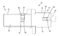
本実施例1のコネクタは、合成樹脂製のハウジング10と、合成樹脂製のリテーナ30と、端子ユニット50とを備えている。ハウジング10は、全体として上下寸法に比べて左右寸法(幅寸法)の大きい扁平な形状をなす。ハウジング10のうち左側の大部分は端子収容部11となっている。端子収容部11の内部には複数の端子収容室12が形成され、各端子収容室12内には、ハウジング10の後方から雌形端子(図示省略)が挿入されている。各雌形端子は、ノイズ対策がされていない電線(図示省略)に接続されている。
The connector of the first embodiment includes a
ハウジング10の右端部には、ハウジング側覆い部13が形成されている。ハウジング側覆い部13は、リテーナ30を取り付ける機能と、端子ユニット50を収容する機能と、端子ユニット50を抜止めする機能とを兼ね備えている。ハウジング側覆い部13の内部空間は、下方(リテーナ30が本係止位置から仮係止位置へ変位するときの移動方向)に開放されているとともに、前後両方にも開放されている。
A housing-
ハウジング側覆い部13は、端子収容部11の右外側面を構成する左前壁部14と、端子収容部11の右端部上縁から右方へ水平に延出した前側上壁部15と、前側上壁部15の右端縁から下方へ延出した右前壁部16とを備えている。ハウジング側覆い部13は、更に、左前壁部14の後端縁から後方へ延出した左後壁部17と、前側上壁部15の後端縁から後方へ延出した後側上壁部18と、右前壁部16の後端縁から後方へ延出した右後壁部19も備えている。
The housing-
左前壁部14の内側面の下端部には、前後方向に延びた支持リブ20が形成されている。左前壁部14と右前壁部16の後端に近い位置には、上方に面する離脱規制用受け部21(左前壁部14の離脱規制用受け部21の図示は省略)が形成されている。前側上壁部15には、左右両離脱規制用受け部21に連通する左右方向の検知用開口部22が形成されている。左後壁部17と右後壁部19には、仮係止用係止孔23と、仮係止用係止孔23より上方に位置する本係止用係止孔24とが形成されている。そして、前側上壁部15の内面(下面)には、前方(端子保持部材51からの電線61の導出方向と反対方向)に面する突起状のストッパ25が形成されている。
A
図9〜11に示すように、リテーナ30は、水平な底壁部31と、底壁部31の左側縁から上方へ立ち上がる左側壁部32Lと、底壁部31の右側縁から上方へ立ち上がる右側壁部32Rとを備えた単一部品である。底壁部31と左側壁部32Lと右側壁部32Rは、リテーナ側覆い部33を構成する。リテーナ側覆い部33の内部空間は、端子ユニット50を収容するスペースであり、ハウジング側覆い部13とは逆に上方(リテーナ30が仮係止位置から本係止位置へ変位するときの移動方向)に開放されているとともに、ハウジング側覆い部13と同じく前後両方にも開放されている。底壁部31の上面(リテーナ側覆い部33の内部)には、後方に面する突起状の前止まり部34が形成されている。
As shown in FIGS. 9 to 11, the
左側壁部32Lの下端部外面には、前後方向に延びた係止リブ35と、係止リブ35の上縁部に沿って前後方向に延びた係止溝36とが形成されている。左側壁部32Lと右側壁部32Rの後端部には、夫々、その下端から上方へ片持ち状に立ち上がった形態であり、左右方向へ弾性変位可能な弾性アーム部37が形成されている。弾性アーム部37の外側面の上端部には、係止突起38が形成されている。
A locking
左側壁部32Lと右側壁部32Rの外側面の上端部には突起状の離脱用規制部39が形成されている。離脱用規制部39は、左側壁部32Lと右側壁部32Rの前後方向における略中央位置に配されている。左側壁部32Lと右側壁部32Rの上端縁同士は、左右方向の梁部40で連結されている。梁部40と離脱用規制部39は、前後方向において同じ位置に配されている。
At the upper end of the outer side surface of the left
リテーナ30は、ハウジング10の下方からハウジング側覆い部13に嵌合され、ハウジング10に対し仮係止位置と本係止位置とに選択的に取り付けられるようになっている。嵌合状態では、リテーナ側覆い部33がハウジング側覆い部13の内部に収容され、左側壁部32Lが左前壁部14と左後壁部17の内面に重なるとともに、右側壁部32Rが右前壁部16と右後壁部19の内面に重なる。そして、底壁部31がハウジング側覆い部13の内部空間の下面を塞ぐ。そして、ハウジング側覆い部13とリテーナ側覆い部33とにより、前後両面が開放された角筒状のユニット収容部41が構成される。ユニット収容部41の後端の開口は、端子ユニット50をユニット収容部41に収容するための挿入口42となる。
The
図5,8に示すように係止溝36が支持リブ20に嵌合するとともに、図7に示すように係止突起38が仮係止用係止孔23に係止することにより、リテーナ30が仮係止位置に保持される。このとき、離脱用規制部39が離脱規制用受け部21に係止することにより、リテーナ30は、ハウジング10に対して下方へ離脱することが規制されているとともに、ハウジング10に対して前後方向へ相対変位することが規制されている。
As shown in FIGS. 5 and 8, the locking
また、図2に示すように係止リブ35が支持リブ20の上面に載置されるように係止するとともに、図1,2に示すように係止突起38が本係止用係止孔24に係止することにより、リテーナ30が本係止位置に保持される。本係止位置は仮係止位置よりも上方の位置である。したがって、リテーナ30が仮係止位置にあるときには、梁部40が検知用開口部22よりも下方に位置するが、リテーナ30が本係止位置へ上昇すると、梁部40が検知用開口部22の内部に進出し、ハウジング10の外部から梁部40の存在を目視確認し易くなる。
The locking
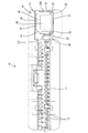
端子ユニット50は、合成樹脂製の端子保持部材51と、一対の端子金具58とを備えて構成され、ツイストペア線62の前端部に接続されている。図12,13に示すように、端子ユニット50は、全体として前後方向に細長く、ハウジング10の後方からユニット収容部41内に挿入されるようになっている。
The
端子保持部材51は、ロアケース52とアッパケース53とを上下に合体させるように組み付けて構成されている。ロアケース52の下面(外面)には、前方に面する突当部54が形成されている。アッパケース53の上面(外面)には、後方に面する抜止め突起55が形成されている。端子保持部材51の内部には左右一対の端子収容空間56が形成され、各端子収容空間56の上面には、前後一対の端子用抜止め部57が形成されている。
The
各端子収容空間56内には、夫々、端子金具58が取り付けられている。端子金具58は、ロアケース52とアッパケース53を合体する際に、端子収容空間56内に収容される。端子金具58は、その前後一対の離脱規制突起59を端子用抜止め部57に係止させることにより、端子保持部材51から後方へ離脱することを規制されている。
各端子金具58の後端部の圧着部60には、夫々、電線61の前端部が個別に接続されている。この電線61は、通信用電線(信号線)として使用されるものであって、螺旋状に捻られることによりノイズ低減機能を有するツイストペア線62を構成している。ツイストペア線62のうち前端部を除いた領域は、2本の電線61がシース63により一括して包囲されている。端子収容空間56の後端部には、シース63の前端部も収容されている。したがって、電線61(ツイストペア線62)は、端子保持部材51から後方へ導出されている。
The front ends of the
端子保持部材51に対する端子金具58の取付け方向(つまり、ロアケース52とアッパケース53の合体方向)は、端子保持部材51からの電線61の導出方向(ツイストペア線62の長さ方向)と交差する方向である。したがって、ツイストペア線62の前端部においてシース63を除去して電線61を露出させる寸法は、端子金具58の圧着部60と電線61を圧着機(アプリケータ)で圧着するために必要な寸法だけでよい。
The direction in which the terminal fitting 58 is attached to the terminal holding member 51 (that is, the direction in which the
コネクタの組付けは、以下の手順で行われる。まず、リテーナ30をハウジング10の仮係止位置に取り付ける。これにより、ハウジング10の右端部には、後端が挿入口42として開口するユニット収容部41が形成される。次に、ハウジング10の後方から端子ユニット50をユニット収容部41内に挿入する。端子ユニット50が正規の挿入位置に到達すると、端子ユニット50の突当部54がリテーナ30の前止まり部34に突き当たり、それ以上の端子ユニット50の挿入動作が規制される。この状態では、抜止め突起55は、ストッパ25よりも僅かに下方の位置で、ストッパ25よりも僅かに前方の位置に配される。
Assembly of the connector is performed in the following procedure. First, the
この状態から底壁部31の下面(外面)を押し上げると、リテーナ30が仮係止位置から本係止位置へ移動し、端子ユニット50もリテーナ30と一体となって仮係止位置から本係止位置へ移動する。この移動に伴い、抜止め突起55がストッパ25と同じ高さに変位し、抜止め突起55の後面がストッパ25の前面に対し近接して前後に対向し係止可能な状態となる。この状態で端子ユニット50に後方への引張力が作用しても、抜止め突起55がストッパ25に係止するので、端子ユニット50はリテーナ30及びハウジング10に対して後方へ相対変位することはない。
When the lower surface (outer surface) of the
リテーナ30を仮係止位置から本係止位置へ移動させるときに、端子ユニット50が正規位置より後方へ位置ずれしていた場合は、抜止め突起55がストッパ25に対し下から当接すので、リテーナ30を本係止位置へ移動させることはできない。したがって、端子ユニット50がハウジング10に対し不正な位置(端子金具58が正規位置よりも後方に外れた位置)に取り付けられることはない。また、リテーナ30が本係止位置へ移動したかどうかは、リテーナ30の梁部40が検知用開口部22内に進出しているか否かを目視することによって、確認することができる。端子ユニット50をハウジング10から外す際には、リテーナ30と端子ユニット50を本係止位置から仮係止位置へ移動させれば、端子ユニット50をハウジング10後方へ抜き取ればよい。
If the
上述のように本実施例のコネクタは、ハウジング10と、ハウジング10に取り付けられ、仮係止位置と本係止位置との間で変位可能なリテーナ30と、リテーナ30に取り付けられることで、リテーナ30と一体となって仮係止位置と本係止位置との間で変位する端子ユニット50とを備えている。端子保持部材51と端子金具58は、端子ユニット50を構成する。端子金具58は、電線61の前端部に固着され、端子保持部材51からの電線61の導出方向(後方)がリテーナ30の変位方向(上下方向)と交差する向きとなるように端子保持部材51に取り付けられている。
As described above, the connector according to the present embodiment is provided with the
ハウジング10には、電線61の導出方向とは反対の方向(前方)に面するストッパ25が形成されている。端子保持部材51には、リテーナ30が仮係止位置にある状態ではストッパ25と非係止であり、リテーナ30が本係止位置へ変位することでストッパ25への係止が可能となる抜止め突起55が形成されている。この構成によれば、電線61が引っ張られると、抜止め突起55がストッパ25に突き当たることにより、端子ユニット50がハウジング10に対して抜止めされる。端子ユニット50を抜止めする手段として、弾性撓み可能なランスを用いていないので、コネクタの小型化(低背化)を実現することができた。また、抜止め突起55とストッパ25は、弾性撓みさせることなく非係止状態から係止状態へ移行させることができるので、抜止め機能の信頼性に優れている。
A
また、リテーナ30がハウジング10に取り付けられた状態では、仮係止位置と本係止位置のいずれであっても、ウジングとリテーナ30とによりユニット収容部41が形成される。ユニット収容部41は、端子ユニット50を全周に亘って包囲するように収容する。この構成によれば、ユニット収容部41に端子ユニット50を収容すれば、端子ユニット50を異物の干渉等から保護できる。
When the
また、ハウジング10には、リテーナ30の本係止位置から仮係止位置への変位方向(下方)に開放されたハウジング側覆い部13が形成され、リテーナ30には、ハウジング側覆い部13と嵌合し得るようにリテーナ側覆い部33が形成されている。リテーナ側覆い部33は、リテーナ30の仮係止位置から本係止位置への変位方向(つまり、ハウジング側覆い部13が開放される方向とは逆の方向)に開放されている。この構成によれば、ユニット収容部41を構成するためにハウジング10やリテーナ30に筒状部を形成する場合に比べると、材料コストを低減できる。
Further, the
また、ユニット収容部41には、端子ユニット50がユニット収容部41に挿入することを可能にするための挿入口42が形成されている。この構成により、リテーナ30をハウジング10に取り付けた後に、端子ユニット50をリテーナ30に取り付けることが実現できた。これにより、リテーナ30に端子ユニット50を取り付けた状態に保持するための手段を省略又は簡素化できるので、リテーナ30や端子ユニット50の構造を簡素化することが可能である。
Further, an
<他の実施例>
本発明は上記記述及び図面によって説明した実施例に限定されるものではなく、例えば次のような実施例も本発明の技術的範囲に含まれる。
(1)上記実施例では、端子ユニットをリテーナに取り付けた状態では端子ユニットが全周に亘って包囲されるようにユニット収容部内に収容されるようにしたが、端子ユニットをリテーナに取り付けた状態で、端子ユニットの周方向における一部が外部に露出するようにしてもよい。
(2)上記実施例では、ユニット収容部を構成するハウジング側覆い部とリテーナ側覆い部の両方が、周方向における一部を開放した形態であるが、ハウジング側覆い部とリテーナ側覆い部の一方又は両方が筒状をなしていてもよい。
(3)上記実施例では、リテーナをハウジングに取り付けた後に、リテーナに端子ユニットを取り付けたが、リテーナをハウジングに取り付ける前に、端子ユニットをリテーナに取り付けてもよい。
<Other embodiments>
The present invention is not limited to the embodiments described with reference to the above description and the drawings. For example, the following embodiments are also included in the technical scope of the present invention.
(1) In the above embodiment, when the terminal unit is attached to the retainer, the terminal unit is accommodated in the unit accommodating portion so as to be surrounded all around, but the terminal unit is attached to the retainer. Thus, a part of the terminal unit in the circumferential direction may be exposed to the outside.
(2) In the above embodiment, both the housing-side cover portion and the retainer-side cover portion constituting the unit housing portion are partially open in the circumferential direction. One or both may be cylindrical.
(3) In the above embodiment, the terminal unit is attached to the retainer after attaching the retainer to the housing. However, the terminal unit may be attached to the retainer before attaching the retainer to the housing.
10…ハウジング
13…ハウジング側覆い部
25…ストッパ
30…リテーナ
33…リテーナ側覆い部
41…ユニット収容部
42…挿入口
50…端子ユニット
51…端子保持部材
54…突当部
58…端子金具
61…電線
DESCRIPTION OF
Claims (4)
前記ハウジングに取り付けられ、仮係止位置と本係止位置との間で変位可能なリテーナと、
前記リテーナとは別体の部材である端子ユニットと、
前記端子ユニットを構成する端子保持部材と、
電線に固着され、前記端子保持部材からの前記電線の導出方向が前記リテーナの変位方向と交差する向きとなるように前記端子保持部材に取り付けられた端子金具と、
前記ハウジングに形成され、前記電線の導出方向とは反対の方向に面するストッパと、
前記端子保持部材に形成され、前記リテーナが仮係止位置にある状態では前記ストッパと非係止であり、前記リテーナが本係止位置へ変位することで前記ストッパへの係止が可能となる抜止め突起とを備え、
前記端子ユニットは、前記リテーナに取り付けられることで、前記リテーナと一体となって仮係止位置と本係止位置との間で変位し、
前記リテーナが前記ハウジングに組み付けられたときに、前記リテーナと前記ハウジングとによってユニット収容部が構成され、
前記ユニット収容部内に前記端子ユニットが収容されるコネクタ。 A housing,
A retainer attached to the housing and displaceable between a temporary locking position and a full locking position;
A terminal unit that is a separate member from the retainer,
A terminal holding member constituting the terminal unit,
A terminal fitting fixed to the wire, and attached to the terminal holding member such that a direction in which the wire is led out from the terminal holding member intersects with a direction in which the retainer is displaced,
A stopper formed on the housing and facing in a direction opposite to a lead-out direction of the electric wire;
The retainer is formed on the terminal holding member and is not locked with the stopper when the retainer is at the temporary locking position. Locking to the stopper is enabled by displacing the retainer to the full locking position. With retaining projections ,
When the terminal unit is attached to the retainer, the terminal unit is displaced between the temporary locking position and the full locking position integrally with the retainer,
When the retainer is assembled to the housing, a unit accommodating portion is configured by the retainer and the housing,
A connector in which the terminal unit is housed in the unit housing .
前記ハウジングに取り付けられ、仮係止位置と本係止位置との間で変位可能なリテーナと、
前記リテーナに取り付けられることで、前記リテーナと一体となって仮係止位置と本係止位置との間で変位する端子ユニットと、
前記端子ユニットを構成する端子保持部材と、
電線に固着され、前記端子保持部材からの前記電線の導出方向が前記リテーナの変位方向と交差する向きとなるように前記端子保持部材に取り付けられた端子金具と、
前記ハウジングに形成され、前記電線の導出方向とは反対の方向に面するストッパと、
前記端子保持部材に形成され、前記リテーナが仮係止位置にある状態では前記ストッパと非係止であり、前記リテーナが本係止位置へ変位することで前記ストッパへの係止が可能となる抜止め突起とを備え、
前記リテーナが前記ハウジングに取り付けられた状態では、前記ハウジングと前記リテーナとにより前記端子ユニットを全周に亘って包囲するように収容するユニット収容部が形成され、
前記ユニット収容部は、
前記ハウジングに形成され、前記リテーナの本係止位置から仮係止位置への変位方向に開放されたハウジング側覆い部と、
前記ハウジング側覆い部と嵌合し得るように前記リテーナに形成され、前記リテーナの仮係止位置から本係止位置への変位方向に開放されたリテーナ側覆い部とを備えているコネクタ。 A housing,
A retainer attached to the housing and displaceable between a temporary locking position and a full locking position;
A terminal unit that is displaced between a temporary locking position and a full locking position integrally with the retainer by being attached to the retainer,
A terminal holding member constituting the terminal unit,
A terminal fitting fixed to the wire and attached to the terminal holding member such that a direction in which the wire is led out from the terminal holding member intersects a direction of displacement of the retainer,
A stopper formed on the housing and facing in a direction opposite to a lead-out direction of the electric wire;
The retainer is formed on the terminal holding member and is not locked with the stopper when the retainer is at the temporary locking position, and the retainer can be locked to the stopper by being displaced to the full locking position. With retaining projections,
In a state where the retainer is attached to the housing, a unit accommodating portion that accommodates the terminal unit so as to surround the terminal unit over the entire circumference is formed by the housing and the retainer,
The unit housing section,
A housing-side cover formed on the housing and opened in a direction of displacement of the retainer from a fully locked position to a temporarily locked position;
A connector formed on the retainer so that the retainer can be fitted to the housing-side cover, the retainer-side cover being open in the direction of displacement of the retainer from the temporary locking position to the final locking position.
Priority Applications (5)
| Application Number | Priority Date | Filing Date | Title |
|---|---|---|---|
| JP2016118636A JP6670446B2 (en) | 2016-06-15 | 2016-06-15 | connector |
| PCT/JP2017/019513 WO2017217208A1 (en) | 2016-06-15 | 2017-05-25 | Connector |
| US16/308,888 US10910753B2 (en) | 2016-06-15 | 2017-05-25 | Connector |
| DE112017003023.4T DE112017003023T5 (en) | 2016-06-15 | 2017-05-25 | Connectors |
| CN201780033531.2A CN109196729B (en) | 2016-06-15 | 2017-05-25 | Connector with a locking member |
Applications Claiming Priority (1)
| Application Number | Priority Date | Filing Date | Title |
|---|---|---|---|
| JP2016118636A JP6670446B2 (en) | 2016-06-15 | 2016-06-15 | connector |
Publications (3)
| Publication Number | Publication Date |
|---|---|
| JP2017224473A JP2017224473A (en) | 2017-12-21 |
| JP2017224473A5 JP2017224473A5 (en) | 2018-06-14 |
| JP6670446B2 true JP6670446B2 (en) | 2020-03-25 |
Family
ID=60663607
Family Applications (1)
| Application Number | Title | Priority Date | Filing Date |
|---|---|---|---|
| JP2016118636A Active JP6670446B2 (en) | 2016-06-15 | 2016-06-15 | connector |
Country Status (5)
| Country | Link |
|---|---|
| US (1) | US10910753B2 (en) |
| JP (1) | JP6670446B2 (en) |
| CN (1) | CN109196729B (en) |
| DE (1) | DE112017003023T5 (en) |
| WO (1) | WO2017217208A1 (en) |
Families Citing this family (1)
| Publication number | Priority date | Publication date | Assignee | Title |
|---|---|---|---|---|
| JP6988446B2 (en) * | 2017-12-21 | 2022-01-05 | 株式会社オートネットワーク技術研究所 | connector |
Family Cites Families (26)
| Publication number | Priority date | Publication date | Assignee | Title |
|---|---|---|---|---|
| JPH0759057B2 (en) | 1990-09-20 | 1995-06-21 | 三菱電機株式会社 | Television receiver |
| JP2538523Y2 (en) * | 1991-05-17 | 1997-06-18 | 日本航空電子工業株式会社 | Twisted pair wire connector |
| US5522740A (en) * | 1994-09-29 | 1996-06-04 | Molex Incorporated | Electrical connector with terminal position assurance device that facilitates fully inserting a terminal |
| CN1187699A (en) * | 1996-04-24 | 1998-07-15 | 住友电装株式会社 | Connector |
| JP3123437B2 (en) * | 1996-07-31 | 2001-01-09 | 住友電装株式会社 | connector |
| JPH1064613A (en) * | 1996-08-19 | 1998-03-06 | Sumitomo Wiring Syst Ltd | Connector |
| JP3806924B2 (en) * | 2001-11-22 | 2006-08-09 | 住友電装株式会社 | connector |
| EP1378968B1 (en) * | 2002-07-04 | 2007-11-07 | Sumitomo Wiring Systems, Ltd. | A connector |
| JP2004055470A (en) | 2002-07-23 | 2004-02-19 | Auto Network Gijutsu Kenkyusho:Kk | Connector |
| JP2007280850A (en) * | 2006-04-10 | 2007-10-25 | Sumitomo Wiring Syst Ltd | Terminal metal fitting |
| JP2008153066A (en) * | 2006-12-18 | 2008-07-03 | Auto Network Gijutsu Kenkyusho:Kk | Branching connector and connector connected to branching connector |
| DE102009052772B4 (en) * | 2008-12-01 | 2014-02-13 | Sumitomo Wiring Systems, Ltd. | A connector |
| JP5598849B2 (en) * | 2010-08-05 | 2014-10-01 | 古河電気工業株式会社 | Connector, connector housing, and connector manufacturing method |
| JP2012079552A (en) * | 2010-10-01 | 2012-04-19 | Sumitomo Wiring Syst Ltd | Connector |
| JP2012216343A (en) * | 2011-03-31 | 2012-11-08 | Sumitomo Wiring Syst Ltd | Connector |
| JP5772468B2 (en) * | 2011-10-06 | 2015-09-02 | 住友電装株式会社 | connector |
| JP5754412B2 (en) * | 2012-04-26 | 2015-07-29 | 住友電装株式会社 | connector |
| JP5846083B2 (en) * | 2012-09-06 | 2016-01-20 | 住友電装株式会社 | connector |
| JP6124134B2 (en) * | 2013-07-26 | 2017-05-10 | 住友電装株式会社 | connector |
| JP6124133B2 (en) * | 2013-07-26 | 2017-05-10 | 住友電装株式会社 | connector |
| JP6040911B2 (en) * | 2013-10-31 | 2016-12-07 | 住友電装株式会社 | connector |
| JP6015628B2 (en) * | 2013-10-31 | 2016-10-26 | 住友電装株式会社 | connector |
| JP6292468B2 (en) * | 2014-01-31 | 2018-03-14 | 住友電装株式会社 | connector |
| JP6195165B2 (en) * | 2014-03-13 | 2017-09-13 | 住友電装株式会社 | connector |
| JP6311396B2 (en) * | 2014-03-28 | 2018-04-18 | 住友電装株式会社 | connector |
| JP2016025045A (en) | 2014-07-24 | 2016-02-08 | 矢崎総業株式会社 | Connection structure for connector and terminal fitting |
-
2016
- 2016-06-15 JP JP2016118636A patent/JP6670446B2/en active Active
-
2017
- 2017-05-25 DE DE112017003023.4T patent/DE112017003023T5/en active Granted
- 2017-05-25 WO PCT/JP2017/019513 patent/WO2017217208A1/en active Application Filing
- 2017-05-25 US US16/308,888 patent/US10910753B2/en active Active
- 2017-05-25 CN CN201780033531.2A patent/CN109196729B/en active Active
Also Published As
| Publication number | Publication date |
|---|---|
| CN109196729A (en) | 2019-01-11 |
| US20200313334A1 (en) | 2020-10-01 |
| WO2017217208A9 (en) | 2018-07-26 |
| US10910753B2 (en) | 2021-02-02 |
| WO2017217208A1 (en) | 2017-12-21 |
| JP2017224473A (en) | 2017-12-21 |
| DE112017003023T5 (en) | 2019-03-14 |
| CN109196729B (en) | 2020-07-17 |
Similar Documents
| Publication | Publication Date | Title |
|---|---|---|
| JP6760147B2 (en) | Shield terminal and shield connector | |
| JP6769353B2 (en) | Terminal unit and connector | |
| JP6665700B2 (en) | connector | |
| JP6769354B2 (en) | Terminal unit and connector | |
| JP6393301B2 (en) | connector | |
| JP4949936B2 (en) | connector | |
| JP6667107B2 (en) | connector | |
| EP1983618A2 (en) | A connector | |
| JP6816668B2 (en) | connector | |
| JP6792797B2 (en) | Terminal unit | |
| JP4569448B2 (en) | connector | |
| KR20170091151A (en) | Wire housing protector | |
| JP5840929B2 (en) | Protector | |
| JP4544065B2 (en) | connector | |
| JP6670446B2 (en) | connector | |
| JP6431883B2 (en) | connector | |
| US10886654B2 (en) | Connector and connector housing | |
| JP5012350B2 (en) | Cover for connector and connector with cover | |
| JP6788556B2 (en) | Electronic unit mounting structure | |
| JP5183315B2 (en) | connector | |
| JP6899738B2 (en) | Connector block and connector housing structure of the connector block | |
| JP5681478B2 (en) | connector | |
| JP2020126826A (en) | Housing and connector | |
| JP6930561B2 (en) | connector | |
| JP2009272239A (en) | Connector |
Legal Events
| Date | Code | Title | Description |
|---|---|---|---|
| A521 | Request for written amendment filed |
Free format text: JAPANESE INTERMEDIATE CODE: A523 Effective date: 20180507 |
|
| A621 | Written request for application examination |
Free format text: JAPANESE INTERMEDIATE CODE: A621 Effective date: 20180925 |
|
| A131 | Notification of reasons for refusal |
Free format text: JAPANESE INTERMEDIATE CODE: A131 Effective date: 20190912 |
|
| A521 | Request for written amendment filed |
Free format text: JAPANESE INTERMEDIATE CODE: A523 Effective date: 20191105 |
|
| TRDD | Decision of grant or rejection written | ||
| A01 | Written decision to grant a patent or to grant a registration (utility model) |
Free format text: JAPANESE INTERMEDIATE CODE: A01 Effective date: 20200130 |
|
| A61 | First payment of annual fees (during grant procedure) |
Free format text: JAPANESE INTERMEDIATE CODE: A61 Effective date: 20200212 |
|
| R150 | Certificate of patent or registration of utility model |
Ref document number: 6670446 Country of ref document: JP Free format text: JAPANESE INTERMEDIATE CODE: R150 |