JP6769353B2 - Terminal unit and connector - Google Patents
Terminal unit and connector Download PDFInfo
- Publication number
- JP6769353B2 JP6769353B2 JP2017046959A JP2017046959A JP6769353B2 JP 6769353 B2 JP6769353 B2 JP 6769353B2 JP 2017046959 A JP2017046959 A JP 2017046959A JP 2017046959 A JP2017046959 A JP 2017046959A JP 6769353 B2 JP6769353 B2 JP 6769353B2
- Authority
- JP
- Japan
- Prior art keywords
- terminal unit
- lance
- locking portion
- housing
- locking
- Prior art date
- Legal status (The legal status is an assumption and is not a legal conclusion. Google has not performed a legal analysis and makes no representation as to the accuracy of the status listed.)
- Active
Links
Images


Classifications
-
- H—ELECTRICITY
- H01—ELECTRIC ELEMENTS
- H01R—ELECTRICALLY-CONDUCTIVE CONNECTIONS; STRUCTURAL ASSOCIATIONS OF A PLURALITY OF MUTUALLY-INSULATED ELECTRICAL CONNECTING ELEMENTS; COUPLING DEVICES; CURRENT COLLECTORS
- H01R13/00—Details of coupling devices of the kinds covered by groups H01R12/70 or H01R24/00 - H01R33/00
- H01R13/40—Securing contact members in or to a base or case; Insulating of contact members
- H01R13/42—Securing in a demountable manner
- H01R13/422—Securing in resilient one-piece base or case, e.g. by friction; One-piece base or case formed with resilient locking means
- H01R13/4223—Securing in resilient one-piece base or case, e.g. by friction; One-piece base or case formed with resilient locking means comprising integral flexible contact retaining fingers
-
- H—ELECTRICITY
- H01—ELECTRIC ELEMENTS
- H01R—ELECTRICALLY-CONDUCTIVE CONNECTIONS; STRUCTURAL ASSOCIATIONS OF A PLURALITY OF MUTUALLY-INSULATED ELECTRICAL CONNECTING ELEMENTS; COUPLING DEVICES; CURRENT COLLECTORS
- H01R13/00—Details of coupling devices of the kinds covered by groups H01R12/70 or H01R24/00 - H01R33/00
- H01R13/02—Contact members
- H01R13/10—Sockets for co-operation with pins or blades
- H01R13/11—Resilient sockets
- H01R13/113—Resilient sockets co-operating with pins or blades having a rectangular transverse section
-
- H—ELECTRICITY
- H01—ELECTRIC ELEMENTS
- H01R—ELECTRICALLY-CONDUCTIVE CONNECTIONS; STRUCTURAL ASSOCIATIONS OF A PLURALITY OF MUTUALLY-INSULATED ELECTRICAL CONNECTING ELEMENTS; COUPLING DEVICES; CURRENT COLLECTORS
- H01R13/00—Details of coupling devices of the kinds covered by groups H01R12/70 or H01R24/00 - H01R33/00
- H01R13/40—Securing contact members in or to a base or case; Insulating of contact members
- H01R13/42—Securing in a demountable manner
- H01R13/436—Securing a plurality of contact members by one locking piece or operation
- H01R13/4361—Insertion of locking piece perpendicular to direction of contact insertion
- H01R13/4362—Insertion of locking piece perpendicular to direction of contact insertion comprising a temporary and a final locking position
-
- H—ELECTRICITY
- H01—ELECTRIC ELEMENTS
- H01R—ELECTRICALLY-CONDUCTIVE CONNECTIONS; STRUCTURAL ASSOCIATIONS OF A PLURALITY OF MUTUALLY-INSULATED ELECTRICAL CONNECTING ELEMENTS; COUPLING DEVICES; CURRENT COLLECTORS
- H01R13/00—Details of coupling devices of the kinds covered by groups H01R12/70 or H01R24/00 - H01R33/00
- H01R13/40—Securing contact members in or to a base or case; Insulating of contact members
- H01R13/42—Securing in a demountable manner
- H01R13/436—Securing a plurality of contact members by one locking piece or operation
- H01R13/4364—Insertion of locking piece from the front
- H01R13/4365—Insertion of locking piece from the front comprising a temporary and a final locking position
-
- H—ELECTRICITY
- H01—ELECTRIC ELEMENTS
- H01R—ELECTRICALLY-CONDUCTIVE CONNECTIONS; STRUCTURAL ASSOCIATIONS OF A PLURALITY OF MUTUALLY-INSULATED ELECTRICAL CONNECTING ELEMENTS; COUPLING DEVICES; CURRENT COLLECTORS
- H01R13/00—Details of coupling devices of the kinds covered by groups H01R12/70 or H01R24/00 - H01R33/00
- H01R13/46—Bases; Cases
- H01R13/502—Bases; Cases composed of different pieces
-
- H—ELECTRICITY
- H01—ELECTRIC ELEMENTS
- H01R—ELECTRICALLY-CONDUCTIVE CONNECTIONS; STRUCTURAL ASSOCIATIONS OF A PLURALITY OF MUTUALLY-INSULATED ELECTRICAL CONNECTING ELEMENTS; COUPLING DEVICES; CURRENT COLLECTORS
- H01R4/00—Electrically-conductive connections between two or more conductive members in direct contact, i.e. touching one another; Means for effecting or maintaining such contact; Electrically-conductive connections having two or more spaced connecting locations for conductors and using contact members penetrating insulation
- H01R4/10—Electrically-conductive connections between two or more conductive members in direct contact, i.e. touching one another; Means for effecting or maintaining such contact; Electrically-conductive connections having two or more spaced connecting locations for conductors and using contact members penetrating insulation effected solely by twisting, wrapping, bending, crimping, or other permanent deformation
- H01R4/18—Electrically-conductive connections between two or more conductive members in direct contact, i.e. touching one another; Means for effecting or maintaining such contact; Electrically-conductive connections having two or more spaced connecting locations for conductors and using contact members penetrating insulation effected solely by twisting, wrapping, bending, crimping, or other permanent deformation by crimping
- H01R4/183—Electrically-conductive connections between two or more conductive members in direct contact, i.e. touching one another; Means for effecting or maintaining such contact; Electrically-conductive connections having two or more spaced connecting locations for conductors and using contact members penetrating insulation effected solely by twisting, wrapping, bending, crimping, or other permanent deformation by crimping for cylindrical elongated bodies, e.g. cables having circular cross-section
- H01R4/184—Electrically-conductive connections between two or more conductive members in direct contact, i.e. touching one another; Means for effecting or maintaining such contact; Electrically-conductive connections having two or more spaced connecting locations for conductors and using contact members penetrating insulation effected solely by twisting, wrapping, bending, crimping, or other permanent deformation by crimping for cylindrical elongated bodies, e.g. cables having circular cross-section comprising a U-shaped wire-receiving portion
- H01R4/185—Electrically-conductive connections between two or more conductive members in direct contact, i.e. touching one another; Means for effecting or maintaining such contact; Electrically-conductive connections having two or more spaced connecting locations for conductors and using contact members penetrating insulation effected solely by twisting, wrapping, bending, crimping, or other permanent deformation by crimping for cylindrical elongated bodies, e.g. cables having circular cross-section comprising a U-shaped wire-receiving portion combined with a U-shaped insulation-receiving portion
-
- H—ELECTRICITY
- H01—ELECTRIC ELEMENTS
- H01R—ELECTRICALLY-CONDUCTIVE CONNECTIONS; STRUCTURAL ASSOCIATIONS OF A PLURALITY OF MUTUALLY-INSULATED ELECTRICAL CONNECTING ELEMENTS; COUPLING DEVICES; CURRENT COLLECTORS
- H01R43/00—Apparatus or processes specially adapted for manufacturing, assembling, maintaining, or repairing of line connectors or current collectors or for joining electric conductors
- H01R43/20—Apparatus or processes specially adapted for manufacturing, assembling, maintaining, or repairing of line connectors or current collectors or for joining electric conductors for assembling or disassembling contact members with insulating base, case or sleeve
Description
本発明は、端子ユニット及びコネクタに関するものである。 The present invention relates to a terminal unit and a connector.
特許文献1には、内導体端子を誘電体に収容した端子ユニットと、端子ユニットを収容するハウジングとを備えたコネクタが開示されている。この種のコネクタにおいて、ハウジングに挿入した端子ユニットを抜止め状態に保持する手段として、ハウジングに形成した弾性撓み可能なランスを、誘電体の外面に形成した係止突起に係止させる構造が考えられる。 Patent Document 1 discloses a connector including a terminal unit in which an inner conductor terminal is housed in a dielectric and a housing in which the terminal unit is housed. In this type of connector, as a means for holding the terminal unit inserted in the housing in a retaining state, a structure in which an elastic flexible lance formed in the housing is locked to a locking projection formed on the outer surface of the dielectric is considered. Be done.
ランスは弾性撓み可能であることから、衝撃や振動等によって係止突起から解離することが懸念される。そのため、端子ユニットを抜止めする機能の信頼性向上を図ることが望まれる。 Since the lance is elastically flexible, there is a concern that it may dissociate from the locking projection due to impact, vibration, or the like. Therefore, it is desired to improve the reliability of the function of retaining the terminal unit.
本発明は上記のような事情に基づいて完成されたものであって、端子ユニットを抜止めする機能の信頼性向上を図ることを目的とする。 The present invention has been completed based on the above circumstances, and an object of the present invention is to improve the reliability of the function of disconnecting and retaining the terminal unit.
第1の発明の端子ユニットは、
内導体を誘電体に収容した形態であり、弾性撓み可能な第1ランスと前記第1ランスの弾性撓みを規制可能なフロントリテーナと第1収容室とを有する第1ハウジングと、弾性撓み可能な第2ランスと第2収容室と前記第2収容室に臨むサイドリテーナとを有する第2ハウジングとに対し選択的に取り付け可能な端子ユニットであって、
前記誘電体の外面には第1係止部と第2係止部とが形成されており、
前記端子ユニットが前記第1収容室に挿入された状態では、前記フロントリテーナが前記第1ランスの弾性撓みを規制し、前記第1係止部が前記第1ランスと係止することで、前記端子ユニットが抜止めされ、
前記端子ユニットが前記第2収容室に挿入された状態では、前記第1係止部と前記第2ランスとの係止及び前記第2係止部と前記サイドリテーナとの係止により前記端子ユニットが抜止めされるようになっているところに特徴を有する。
The terminal unit of the first invention is
A first housing having an inner conductor housed in a dielectric, a first lance that can be elastically flexed, a front retainer that can regulate the elastic flexing of the first lance, and a first housing chamber, and a first housing that is elastically flexible. A terminal unit that can be selectively attached to a second housing having a second lance, a second accommodation chamber, and a side retainer facing the second accommodation chamber.
A first locking portion and a second locking portion are formed on the outer surface of the dielectric.
When the terminal unit is inserted into the first accommodation chamber, the front retainer regulates the elastic deflection of the first lance, and the first locking portion locks with the first lance. The terminal unit is pulled out,
When the terminal unit is inserted into the second storage chamber, the terminal unit is locked by locking the first locking portion and the second lance and locking the second locking portion and the side retainer. It is characterized in that it is designed to be pulled out.
第2の発明のコネクタは、
内導体を誘電体に収容した形態の端子ユニットを、第1ハウジングに形成した第1収容室と第2ハウジングに形成した第2収容室のうちいずれかの前記収容室に選択的に挿入されることで構成されるものであり、
前記第1収容室に形成された弾性撓み可能な第1ランスと、
前記第1ハウジングに取り付けられることで、前記第1ランスの弾性撓みを規制するフロントリテーナと、
前記第2収容室に形成された弾性撓み可能な第2ランスと、
前記第2収容室内に臨むように前記第2ハウジングに取り付けられるサイドリテーナと、
前記誘電体の外面に形成され、前記端子ユニットが前記第1収容室に挿入されたときには前記第1ランスと係止することで前記端子ユニットを抜止めし、前記端子ユニットが前記第2収容室に挿入されたときには前記第2ランスと係止することで前記端子ユニットを抜止めする第1係止部と、
前記誘電体の外面に形成され、前記端子ユニットが前記第2収容室に挿入されたときには前記サイドリテーナと係止することで前記端子ユニットを抜止めする第2係止部とを備えているところに特徴を有する。
The connector of the second invention is
The terminal unit in the form of accommodating the inner conductor in a dielectric is selectively inserted into either the first accommodating chamber formed in the first housing or the second accommodating chamber formed in the second housing. It is composed of
An elastically flexible first lance formed in the first storage chamber,
A front retainer that regulates the elastic deflection of the first lance by being attached to the first housing,
An elastically flexible second lance formed in the second storage chamber,
A side retainer attached to the second housing so as to face the second storage chamber, and
The terminal unit is formed on the outer surface of the dielectric, and when the terminal unit is inserted into the first storage chamber, the terminal unit is retracted by engaging with the first lance, and the terminal unit is inserted into the second storage chamber. A first locking portion that locks the terminal unit by locking it with the second lance when it is inserted into
A place provided with a second locking portion formed on the outer surface of the dielectric and locking the terminal unit with the side retainer when the terminal unit is inserted into the second accommodating chamber. It has the characteristics of.
第1収容室に端子ユニットを挿入したときは、第1係止部を第1ランスに係止させるとともに、フロントリテーナを第1ハウジングに取り付けて第1ランスの弾性撓みを規制することで、端子ユニットを確実に抜止めすることができる。第2収容室に端子ユニットを挿入したときには、第1係止部を第2ランスに係止させるとともに、第2係止部にサイドリテーナを係止させることで、端子ユニットを確実に抜止めすることができる。端子ユニットは、タイプの異なる第1ハウジングと第2ハウジングに対して共通の部材として使用することができる。 When the terminal unit is inserted into the first accommodation chamber, the terminal is locked by locking the first locking portion to the first lance and attaching the front retainer to the first housing to regulate the elastic deflection of the first lance. The unit can be reliably removed. When the terminal unit is inserted into the second accommodation chamber, the terminal unit is securely retracted by locking the first locking portion to the second lance and locking the side retainer to the second locking portion. be able to. The terminal unit can be used as a common member for different types of first housing and second housing.
第1及び第2の発明は、前記第1係止部と前記第2係止部が、前記誘電体の外面のうち、前記第1収容室及び前記第2収容室への挿入方向と交差する方向に関して反対側の領域に配されていてもよい。
この構成によれば、第1係止部と第2係止部が別々の領域に配されているので、第1係止部と第2係止部の形状や配置等設計する際の自由度が高い。
In the first and second inventions, the first locking portion and the second locking portion intersect the insertion directions of the dielectric in the first storage chamber and the second storage chamber on the outer surface of the dielectric. It may be arranged in the area opposite to the direction.
According to this configuration, since the first locking portion and the second locking portion are arranged in separate regions, the degree of freedom in designing the shape and arrangement of the first locking portion and the second locking portion Is high.
第1及び第2の発明は、前記誘電体の外面のうち前記第2係止部が配されている領域には、前記第1収容室又は前記第2収容室に挿入された前記端子ユニットが正規挿入位置を超えて移動することを規制する前止まり部が形成されていてもよい。
この構成によれば、第2係止部が形成されている領域は、第1ランスや第2ランスが弾性的に当接しないので、前止まり部を形成しても、第1ランスや第2ランスとの弾性的な干渉に起因する挿入抵抗が生じることはない。
In the first and second inventions, the terminal unit inserted into the first accommodating chamber or the second accommodating chamber is located in a region of the outer surface of the dielectric in which the second locking portion is arranged. A front stop may be formed to regulate movement beyond the normal insertion position.
According to this configuration, since the first lance and the second lance do not elastically contact the region where the second locking portion is formed, even if the front stop portion is formed, the first lance and the second lance and the second lance are formed. There is no insertion resistance due to elastic interference with the lance.
第1及び第2の発明は、前記第2係止部と前記前止まり部が単一の突起部に一体形成されていてもよい。
この構成によれば、第2係止部と前止まり部を別々に突出させた形態に比べると、第2係止部と前止まり部の強度を高めることができる。
In the first and second inventions, the second locking portion and the front stop portion may be integrally formed on a single protrusion.
According to this configuration, the strength of the second locking portion and the front stopping portion can be increased as compared with the form in which the second locking portion and the front stopping portion are projected separately.
<実施例1>
以下、本発明を具体化した実施例1を図1〜図13を参照して説明する。尚、以下の説明において、前後の方向については、図1〜4,6〜13における左方を前方と定義する。上下の方向については、図1〜8,10〜13にあらわれる向きを、そのまま上方、下方と定義する。
<Example 1>
Hereinafter, Example 1 embodying the present invention will be described with reference to FIGS. 1 to 13. In the following description, the front-back direction is defined as the front in FIGS. 1 to 4, 6 to 13. Regarding the vertical direction, the directions appearing in FIGS. 1 to 8 and 10 to 13 are defined as upward and downward as they are.
本実施例1の端子ユニット30は、第1ハウジング10に取り付けられることで防水タイプの第1コネクタA(請求項に記載のコネクタ)を構成するとともに、第2ハウジング20に取り付けられることで非防水タイプの第2コネクタB(請求項に記載のコネクタ)を構成する。
The
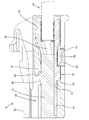
第1ハウジング10は、合成樹脂製であり、図7,8に示すように、収容部11と、収容部11の外周から前方へ且つ収容部11を全周に亘って包囲する筒状嵌合部12とを有する単一部品である。収容部11の内部には第1収容室13が形成されている。第1収容室13には、第1ハウジング10の後方から端子ユニット30が挿入されるようになっている。第1収容室13の内部上面には、前方へ片持ち状に延出した形態であって上方へ弾性撓み可能な第1ランス14が形成されている。第1収容室13の内部下面には、段差状の第1ストッパ15が形成されている。
The
収容部11には、第1ランス14が上方へ弾性撓みすることを許容するための撓み空間16が形成されている。収容部11には、第1ハウジング10の前方からフロントリテーナ17が取り付けられている。収容部11に取り付けたフロントリテーナ17は、図6,8に示すように、撓み空間16の前方へ退避して第1ランス14の弾性撓みを許容する仮係止位置と、図7に示すように、撓み空間16内に進出して第1ランス14の弾性撓みを規制する本係止位置との間で前後方向に移動可能となっている。
A
撓み空間16は、収容部11の外周面には開口せず、収容部11の前端面に開口している。また、収容部11の外周後端部にはシールリング18が取り付けられている。収容部11の外周と筒状嵌合部12の内周との間にフード状の相手側ハウジング(図示省略)が嵌合すると、収容部11と相手側ハウジングとの間はシールリング18によって防水される。
The bending
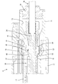
第2ハウジング20は、合成樹脂製である。図3,4に示すように、第2ハウジング20の内部には、第2収容室21が形成されている。第2収容室21には、第2ハウジング20の後方から端子ユニット30が挿入されるようになっている。第2収容室21の内部上面には、前方へ片持ち状に延出した形態であって上方へ弾性撓み可能な第2ランス22が形成されている。第2収容室21の内部下面には、段差状の第2ストッパ23が形成されている。
The
第2ハウジング20には、その下面(外面)から第2収容室21内に連通する取付孔24が形成されている。取付孔24には、サイドリテーナ25が取り付けられている。取付孔24に取り付けたサイドリテーナ25は、図4に示すように、第2収容室21の外部へ退避した仮係止位置と、図3に示すように、第2収容室21内に進出した本係止位置との間で上下方向(第2収容室21に対する端子ユニット30の挿抜方向と交差する方向)に移動し得るようになっている。
The
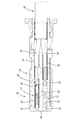
端子ユニット30は、自動車のイーサネット(登録商標)高速通信回路用のワイヤーハーネスを構成する接続部材であり、一対の内導体31を誘電体36に収容して構成されている。内導体31は、全体として前後方向に細長い形状である。内導体31の前端部には、角筒状の本体部32が形成されている。本体部32内には、内導体31の前方からタブ状の相手側導体(図示省略)が挿入され、相手側導体と内導体31が導通可能に接続されるようになっている。内導体31の後端部には、オープンバレル状の圧着部33が形成され、圧着部33には電線34の前端部が導通可能に固着されている。2つの内導体31に接続された一対の電線34はツイストペア線35を構成する。
The
誘電体36は、半割状をなす合成樹脂製の第1部品37と、半割状をなす合成樹脂製の第2部品47とを、上下方向(電線34の前端部の軸線と交差する方向)に合体させて構成されている。第1部品37と第2部品47の材料、材質は、ポリブチレンテレフタレート(PBT)である。
The dielectric 36 has a half-split synthetic resin
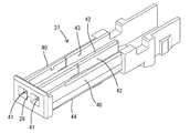
第1部品37は、前後方向に細長い上壁部38と、上壁部38の前端縁から下方へ延出した前壁部39と、上壁部38の左右両側縁から下方へ延出した左右一対の側壁部40とを有する。前壁部39には、相手側導体を挿入させるための左右一対の挿入口41が、貫通形態で形成されている。第1部品37には、上壁部38の前後方向中央部から下方へ延出した隔壁部42が形成され、一対の側壁部40と隔壁部42との間の領域は、前後方向に細長い左右一対の溝部43となっている。左右一対の側壁部40の外側面には、段差状をなす左右一対のロック部44が形成されている。
The
上壁部38の上面(外面)には、突起状をなす第1係止部45が一体に形成されている。第1係止部45は、前後方向においては上壁部38の略中央部であり、左右方向においては上壁部38の中央に配されている。第1係止部45の前端部には、前後方向(ハウジングに対する端子ユニット30の挿入方向)に対して傾斜した傾斜面46が形成されている。第1係止部45の後端面は、前後方向に対して略直角な係止面となっている。
A protrusion-shaped first locking
第2部品47は、前後方向に細長い底壁部48と、底壁部48の前端部における左右両側縁から上方へ延出した左右一対の前側外壁部49と、底壁部48の後端部における左右両側縁から上方へ延出した左右一対の後側外壁部50とを有している。これらの外壁部49,50の延出端部の内面には、ロック突起51が形成されている。
The
底壁部48の下面(外面)には、前後方向のリブ状をなす突起部52が形成されている。突起部52は、前後方向においては底壁部48の略中央位置に配され、左右方向においては底壁部48の中央位置に配されている。突起部52の前端部は、前後方向に対して略直角な前止まり面を有する前止まり部53となっている。突起部52の後端部は、前後方向に対して略直角な係止面を有する第2係止部54となっている。
A rib-shaped
第1部品37と第2部品47を組み付ける際には、第1部品37の左右両溝部43に一対の内導体31を収容する。第1部品37と第2部品47は、電線34の前端部と略直角に交差する上下方向に分割し、且つ合体する形態なので、内導体31を第1部品37に取り付けるときの移動方向も、電線34の前端部の軸線と略直角に交差する方向である。これにより、ツイストペア線35を構成する2本の電線34の前端部においては、電線34の撚りを解く長さを極力短く抑えることができるので、電線34の撚りを解くことに起因するノイズ低減機能の低下を回避できる。
When assembling the
第1部品37に一対の内導体31を取り付けた後、第1部品37に対し第2部品47を下方から合体させるようにして組み付ける。合体した第1部品37と第2部品47は、ロック突起51とロック部44との係止によって合体状態に保持される。第1部品37に対する第2部品47の組付け方向は、電線34の前端部の軸線と略直角に交差する方向である。第1部品37と第2部品47を合体すると、誘電体36が構成されるとともに、誘電体36内に一対の内導体31が収容された状態に組付けられ、端子ユニット30の組付けが完了する。
After attaching the pair of
端子ユニット30を第1ハウジング10に取り付ける際には、予め、ツイストペア線35の外周にゴム栓19を取り付けておき、フロントリテーナ17を仮係止位置に保持した状態で、端子ユニット30を第1ハウジング10の後方から第1収容室13に挿入する。端子ユニット30の挿入過程では、第1係止部45の傾斜面46が第1ランス14を弾性撓みさせる。
When attaching the
端子ユニット30が正規挿入されると、前止まり部53が第1ストッパ15に突き当たることで端子ユニット30が前止まりされるとともに、第1係止部45が第1ランス14に係止することで、端子ユニット30が第1ハウジング10に対し抜止めされる。また、第1収容室13の後端の開口がゴム栓19によって液密状に閉塞される。以上により、端子ユニット30が一次係止される。
When the
端子ユニット30を正規挿入した後、仮係止位置のフロントリテーナ17を、本係止位置へ押し込み、撓み空間16内に進出させる。これにより、第1ランス14が第1係止部45から解離する方向への弾性撓みを規制されるので、端子ユニット30は、二次係止状態となる。このように、端子ユニット30は、第1ランス14による一次係止とフロントリテーナ17による二次係止により、確実に抜止めされる。
After the
端子ユニット30を第2ハウジング20に取り付ける際には、サイドリテーナ25を仮係止位置に保持した状態で、端子ユニット30を第2収容室21に挿入する。端子ユニット30の挿入過程では、第1係止部45の傾斜面46が第2ランス22を弾性撓みさせる。端子ユニット30が正規挿入されると、前止まり部53が第2ストッパ23に突き当たることで端子ユニット30が前止まりされるとともに、第1係止部45が第2ランス22に係止することで、端子ユニット30が第2ハウジング20に対し抜止めされる。以上により、端子ユニット30が一次係止される。
When attaching the
端子ユニット30を正規挿入した後、仮係止位置のサイドリテーナ25を、本係止位置へ押し込み、第2収容室21内に進出させる。これにより、サイドリテーナ25が第2係止部54に対し後方から係止するので、端子ユニット30は、二次係止状態となる。このように、端子ユニット30は、第2ランス22による一次係止とサイドリテーナ25による二次係止により、確実に抜止めされる。
After the
また、第1部品37の前壁部39の挿入口41には相手側導体(図示省略)が挿入されるようになっているので、第1部品37の材料又は材質を、比較的機械的強度の高い材料又は材質であるポリブチレンテレフタレートとした。したがって、相手側導体が前壁部39と干渉しても、相手側導体が前壁部39に突き刺さる虞はない。尚、第2部品47の材料又は材質も、第1部品37と同じく、ポリブチレンテレフタレートとした。
Further, since the mating conductor (not shown) is inserted into the
本実施例1の第1コネクタAは、内導体31を誘電体36に収容した形態の端子ユニット30を、第1ハウジング10に形成した第1収容室13に挿入されることで構成されている。また、第2コネクタBは、端子ユニット30を、第2ハウジング20に形成した第2収容室21に挿入されることで構成されている。つまり、端子ユニット30は、第1ハウジング10と第2ハウジング20とに対し選択的に取り付けられるようになっている。換言すると、端子ユニット30は、第1ハウジング10と第2ハウジング20の双方に取付け可能であり、且つ必要に応じて第1ハウジング10と第2ハウジング20のうちいずれか一方に取り付けるようにしたものである。
The first connector A of the first embodiment is configured by inserting the
第1ハウジング10は、弾性撓み可能な第1ランス14と、第1ランス14の弾性撓みを規制可能なフロントリテーナ17と、第1収容室13とを有している。第2ハウジング20は、弾性撓み可能な第2ランス22と、第2収容室21と、第2収容室21に臨むサイドリテーナ25とを有している。
The
誘電体36の外面には第1係止部45と第2係止部54とが形成されている。端子ユニット30が第1収容室13に挿入された状態では、第1係止部45が第1ランス14に係止するとともに、フロントリテーナ17が第1ランス14の弾性撓みを規制し、以上により、端子ユニット30が確実に抜止めされる。また、端子ユニット30が第2収容室21に挿入された状態では、第1係止部45と第2ランス22との係止及び第2係止部54とサイドリテーナ25との係止により、端子ユニット30が確実に抜止めされる。
A
このように、本実施例1の端子ユニット30は、第1ハウジング10と第2ハウジング20のいずれに取り付けた場合でも、端子ユニット30を抜止めする機能の信頼性に優れている。また、端子ユニット30は、タイプの異なる防水用の第1ハウジング10と非防水用第2ハウジング20に対して共通の部材として使用することができる。
As described above, the
また、第1係止部45と第2係止部54は、誘電体36の外面のうち、第1収容室13及び第2収容室21への挿入方向と交差する上下方向に関して反対側の領域に配されている。この構成によれば、第1係止部45と第2係止部54が別々の領域に配されているので、第1係止部45と第2係止部54の形状や配置等設計する際の自由度が高い。
Further, the
また、誘電体36の外面のうち第2係止部54が配されている領域(底壁部48の外面)には、第1収容室13又は第2収容室21に挿入された端子ユニット30が正規挿入位置を超えて移動することを規制する前止まり部53が形成されている。この構成によれば、第2係止部54が形成されている領域は、第1ランス14や第2ランス22が弾性的に当接しないので、前止まり部53を形成しても、第1ランス14や第2ランス22との弾性的な干渉に起因する挿入抵抗が生じることはない。
Further, in the region (outer surface of the bottom wall portion 48) where the
また、第2係止部54と前止まり部53は、単一の突起部52に一体に形成されている。このように第2係止部54と前止まり部53が繋がった形態となっているので、第2係止部54と前止まり部53を別々に突出させた形態に比べると、第2係止部54と前止まり部53の強度が高められている。
Further, the
<他の実施例>
本発明は上記記述及び図面によって説明した実施例に限定されるものではなく、例えば次のような実施例も本発明の技術的範囲に含まれる。
(1)上記実施例1では、第1係止部と第2係止部を誘電体の外面の互いに反対側の領域に配したが、第1係止部と第2係止部を、誘電体の外面における同一平面上に配してもよい。
(2)上記実施例では、第2係止部と前止まり部を単一の突起部に一体形成したが、第2係止部と前止まり部を独立した突起状としてもよい。
(3)上記実施例1では、第1係止部の数を1つだけとしたが、第1係止部の数は2つ以上でもよい。
(4)上記実施例1では、第2係止部の数を1つだけとしたが、第2係止部の数は2つ以上でもよい。
(5)上記実施例1では、前止まり部の数を1つだけとしたが、前止まり部の数は2つ以上でもよい。
(6)上記実施例1では、1つの誘電体に2つの内導体を収容したが、1つの誘電体に収容する内導体の数は、1つ又は3つ以上であってもよい。
(7)上記実施例1では、誘電体が第1部品と第2部品との2部品で構成されているが、誘電体は単一部品であってもよい。
(8)上記実施例1では、一対の内導体に接続した2本の電線がツイストペア線を構成するものであるが、本発明は、内導体に接続する電線がツイストペア線を構成しない場合にも適用できる。
(9)上記実施例1では、第1部品の材料、材質をポリブチレンテレフタレート(PBT)としたが、第1部品の材料、材質はポリブチレンテレフタレート以外であってもよい。
(10)上記実施例1では、第2部品の材料、材質をポリブチレンテレフタレート(PBT)としたが、第2部品の材料、材質はポリブチレンテレフタレート以外であってもよい。
(11)上記実施例1では、第1部品と第2部品の材料又は材質の組合せが、共に、ポリブチレンテレフタレート(PBT)であるが、第1部品と第2部品の材料又は材質の組合せは、ポリエチレンテレフタレート(PET)とポリプロピレン(PP)としてもよく、ポリブチレンテレフタレートとポリエチレン(PE)としてもよく、ポリブチレンテレフタレートと発泡ポリブチレンテレフタレートとしてもよい。
<Other Examples>
The present invention is not limited to the examples described by the above description and drawings, and for example, the following examples are also included in the technical scope of the present invention.
(1) In the first embodiment, the first locking portion and the second locking portion are arranged in regions opposite to each other on the outer surface of the dielectric, but the first locking portion and the second locking portion are dielectric. It may be arranged on the same plane on the outer surface of the body.
(2) In the above embodiment, the second locking portion and the front stop portion are integrally formed on a single protrusion, but the second locking portion and the front stop may be formed as independent protrusions.
(3) In the first embodiment, the number of the first locking portions is only one, but the number of the first locking portions may be two or more.
(4) In the first embodiment, the number of the second locking portions is only one, but the number of the second locking portions may be two or more.
(5) In the first embodiment, the number of front stop portions is only one, but the number of front stop portions may be two or more.
(6) In the first embodiment, two inner conductors are housed in one dielectric, but the number of inner conductors housed in one dielectric may be one or three or more.
(7) In the first embodiment, the dielectric is composed of two parts, a first part and a second part, but the dielectric may be a single part.
(8) In the first embodiment, the two electric wires connected to the pair of inner conductors form a twisted pair wire, but the present invention also describes the case where the electric wires connected to the inner conductor do not form a twisted pair wire. Applicable.
(9) In the first embodiment, the material and material of the first component are polybutylene terephthalate (PBT), but the material and material of the first component may be other than polybutylene terephthalate.
(10) In the first embodiment, the material and material of the second component are polybutylene terephthalate (PBT), but the material and material of the second component may be other than polybutylene terephthalate.
(11) In the first embodiment, the material or material combination of the first component and the second component is both polybutylene terephthalate (PBT), but the material or material combination of the first component and the second component is , Polyethylene terephthalate (PET) and polypropylene (PP), polybutylene terephthalate and polyethylene (PE), polybutylene terephthalate and foamed polybutylene terephthalate.
A…第1コネクタ(コネクタ)
B…第2コネクタ(コネクタ)
10…第1ハウジング
13…第1収容室
14…第1ランス
17…フロントリテーナ
20…第2ハウジング
21…第2収容室
22…第2ランス
25…サイドリテーナ
30…端子ユニット
31…内導体
36…誘電体
45…第1係止部
52…突起部
53…前止まり部
54…第2係止部
A ... 1st connector (connector)
B ... 2nd connector (connector)
10 ...
Claims (5)
前記誘電体の外面には第1係止部と第2係止部とが形成されており、
前記端子ユニットが前記第1収容室に挿入された状態では、前記フロントリテーナが前記第1ランスの弾性撓みを規制し、前記第1係止部が前記第1ランスと係止することで、前記端子ユニットが抜止めされ、
前記端子ユニットが前記第2収容室に挿入された状態では、前記第1係止部と前記第2ランスとの係止及び前記第2係止部と前記サイドリテーナとの係止により前記端子ユニットが抜止めされるようになっている端子ユニット。 A first housing having an inner conductor housed in a dielectric, a first lance that can be elastically flexed, a front retainer that can regulate the elastic flexing of the first lance, and a first housing chamber, and a first housing that is elastically flexible. A terminal unit that can be selectively attached to a second housing having a second lance, a second accommodation chamber, and a side retainer facing the second accommodation chamber.
A first locking portion and a second locking portion are formed on the outer surface of the dielectric.
When the terminal unit is inserted into the first accommodation chamber, the front retainer regulates the elastic deflection of the first lance, and the first locking portion locks with the first lance. The terminal unit is pulled out,
When the terminal unit is inserted into the second storage chamber, the terminal unit is locked by locking the first locking portion and the second lance and locking the second locking portion and the side retainer. end child unit but that has come to be fit retaining.
内導体を誘電体に収容した形態であり、前記第1収容室と前記第2収容室のうちいずれか一方の前記収容室に選択的に挿入される端子ユニットと、
前記誘電体の外面に形成され、前記端子ユニットが前記第1収容室に挿入されたときには前記第1ランスと係止することで前記端子ユニットを抜止めし、前記端子ユニットが前記第2収容室に挿入されたときには前記第2ランスと係止することで前記端子ユニットを抜止めする第1係止部と、
前記誘電体の外面に形成され、前記端子ユニットが前記第2収容室に挿入されたときには前記サイドリテーナと係止することで前記端子ユニットを抜止めする第2係止部とを備えているコネクタ。 A first housing having a first accommodating chamber in which an elastically flexible first lance was formed and a front retainer for regulating the elastic deflection of the first lance was attached, and an elastically flexible second lance were formed. The housing of one of the second housings having the second accommodation chamber and to which the side retainer is attached so as to face the second accommodation chamber.
A terminal unit in which the inner conductor is housed in a dielectric and is selectively inserted into the storage chamber of either the first storage chamber or the second storage chamber .
The terminal unit is formed on the outer surface of the dielectric, and when the terminal unit is inserted into the first storage chamber, the terminal unit is retracted by engaging with the first lance, and the terminal unit is inserted into the second storage chamber. A first locking portion that locks the terminal unit by locking it with the second lance when it is inserted into
Wherein formed on the outer surface of the dielectric, when the terminal unit is inserted into the second housing chamber is provided with a second locking portion for retaining fit the terminal unit by the side retainer and the locking Turkey Connector.
Priority Applications (5)
| Application Number | Priority Date | Filing Date | Title |
|---|---|---|---|
| JP2017046959A JP6769353B2 (en) | 2017-03-13 | 2017-03-13 | Terminal unit and connector |
| CN201880015962.0A CN110383593B (en) | 2017-03-13 | 2018-02-21 | Terminal unit and connector |
| DE112018001310.3T DE112018001310T5 (en) | 2017-03-13 | 2018-02-21 | Connection unit and connector |
| PCT/JP2018/006265 WO2018168367A1 (en) | 2017-03-13 | 2018-02-21 | Terminal unit and connector |
| US16/492,974 US10833444B2 (en) | 2017-03-13 | 2018-02-21 | Terminal unit and connector |
Applications Claiming Priority (1)
| Application Number | Priority Date | Filing Date | Title |
|---|---|---|---|
| JP2017046959A JP6769353B2 (en) | 2017-03-13 | 2017-03-13 | Terminal unit and connector |
Publications (3)
| Publication Number | Publication Date |
|---|---|
| JP2018152215A JP2018152215A (en) | 2018-09-27 |
| JP2018152215A5 JP2018152215A5 (en) | 2019-09-05 |
| JP6769353B2 true JP6769353B2 (en) | 2020-10-14 |
Family
ID=63522150
Family Applications (1)
| Application Number | Title | Priority Date | Filing Date |
|---|---|---|---|
| JP2017046959A Active JP6769353B2 (en) | 2017-03-13 | 2017-03-13 | Terminal unit and connector |
Country Status (5)
| Country | Link |
|---|---|
| US (1) | US10833444B2 (en) |
| JP (1) | JP6769353B2 (en) |
| CN (1) | CN110383593B (en) |
| DE (1) | DE112018001310T5 (en) |
| WO (1) | WO2018168367A1 (en) |
Families Citing this family (9)
| Publication number | Priority date | Publication date | Assignee | Title |
|---|---|---|---|---|
| JP6750540B2 (en) * | 2017-03-10 | 2020-09-02 | 株式会社オートネットワーク技術研究所 | Shield terminal and shield connector |
| JP6769354B2 (en) * | 2017-03-13 | 2020-10-14 | 株式会社オートネットワーク技術研究所 | Terminal unit and connector |
| JP6769353B2 (en) * | 2017-03-13 | 2020-10-14 | 株式会社オートネットワーク技術研究所 | Terminal unit and connector |
| JP6922884B2 (en) * | 2018-12-28 | 2021-08-18 | 株式会社オートネットワーク技術研究所 | Connector and connector structure |
| JP6982587B2 (en) * | 2019-02-27 | 2021-12-17 | 矢崎総業株式会社 | connector |
| JP7025374B2 (en) * | 2019-06-11 | 2022-02-24 | 矢崎総業株式会社 | housing |
| AT523021B1 (en) * | 2019-09-24 | 2023-03-15 | Neutrik Ag | Electrical connector |
| JP7392349B2 (en) * | 2019-09-24 | 2023-12-06 | 住友電装株式会社 | communication cable |
| JP2022127235A (en) * | 2021-02-19 | 2022-08-31 | 住友電装株式会社 | connector |
Family Cites Families (50)
| Publication number | Priority date | Publication date | Assignee | Title |
|---|---|---|---|---|
| JP2813717B2 (en) * | 1993-04-28 | 1998-10-22 | 矢崎総業株式会社 | Shield connector |
| JP2817087B2 (en) * | 1993-12-21 | 1998-10-27 | 矢崎総業株式会社 | Double locking connector |
| US5622521A (en) * | 1994-09-29 | 1997-04-22 | Molex Incorporated | Electrical connector with terminal position assurance device that facilitates fully inserting a terminal |
| JPH10162888A (en) * | 1996-11-27 | 1998-06-19 | Yazaki Corp | Connector housing with double lock structure |
| JPH10321280A (en) * | 1997-05-16 | 1998-12-04 | Sumitomo Wiring Syst Ltd | Connector |
| JP4514356B2 (en) * | 2001-04-20 | 2010-07-28 | 株式会社オートネットワーク技術研究所 | Shield connector |
| EP1548892B1 (en) * | 2002-09-25 | 2012-04-04 | Mitsubishi Cable Industries, Ltd. | Electrical connector |
| WO2005043683A2 (en) * | 2003-09-20 | 2005-05-12 | Hirschmann Electronics Gmbh & Co. Kg | Plug or coupler of a coaxial plug-in connection in a waterproof embodiment |
| JP4760683B2 (en) * | 2006-11-20 | 2011-08-31 | 住友電装株式会社 | connector |
| JP2009123373A (en) * | 2007-11-12 | 2009-06-04 | Sumitomo Wiring Syst Ltd | Connector |
| JP5217458B2 (en) * | 2008-01-29 | 2013-06-19 | 住友電装株式会社 | connector |
| JP4823284B2 (en) * | 2008-09-19 | 2011-11-24 | タイコエレクトロニクスジャパン合同会社 | Electrical connector |
| JP5472679B2 (en) * | 2009-04-07 | 2014-04-16 | 住友電装株式会社 | connector |
| JP5423233B2 (en) * | 2009-08-18 | 2014-02-19 | 住友電装株式会社 | connector |
| JP5353676B2 (en) * | 2009-12-16 | 2013-11-27 | 住友電装株式会社 | connector |
| JP2012129103A (en) | 2010-12-16 | 2012-07-05 | Yazaki Corp | Coaxial connector |
| JP5637015B2 (en) * | 2011-03-04 | 2014-12-10 | 住友電装株式会社 | connector |
| JP5614369B2 (en) * | 2011-05-19 | 2014-10-29 | 住友電装株式会社 | Terminal fitting |
| US8454378B2 (en) * | 2011-08-31 | 2013-06-04 | Yazaki North America, Inc. | Connector |
| JP5282156B1 (en) * | 2012-04-27 | 2013-09-04 | 日本航空電子工業株式会社 | connector |
| EP2875554B1 (en) | 2012-07-23 | 2022-02-09 | Molex, LLC | Electrical harness connector system with differential pair connection link |
| JP5804041B2 (en) * | 2013-12-26 | 2015-11-04 | 第一精工株式会社 | Electrical connector |
| US9142904B2 (en) * | 2014-01-14 | 2015-09-22 | Tyco Electronics Corporation | Electrical connector with terminal position assurance |
| JP6230471B2 (en) * | 2014-04-09 | 2017-11-15 | ホシデン株式会社 | connector |
| JP6307529B2 (en) * | 2016-01-07 | 2018-04-04 | 矢崎総業株式会社 | Terminal locking structure and connector |
| JP6462601B2 (en) * | 2016-01-12 | 2019-01-30 | 株式会社オートネットワーク技術研究所 | connector |
| WO2017122779A1 (en) * | 2016-01-13 | 2017-07-20 | 株式会社オートネットワーク技術研究所 | Connector |
| US9799983B2 (en) * | 2016-01-20 | 2017-10-24 | Te Connectivity Corporation | Connector assembly |
| JP6515825B2 (en) | 2016-01-21 | 2019-05-22 | 住友電装株式会社 | connector |
| JP6708025B2 (en) * | 2016-07-04 | 2020-06-10 | 株式会社オートネットワーク技術研究所 | Shielded connector |
| JP6404277B2 (en) * | 2016-07-12 | 2018-10-10 | 矢崎総業株式会社 | connector |
| KR102442757B1 (en) * | 2016-07-15 | 2022-09-13 | 히르슈만 오토모티브 게엠베하 | Temperature-resistant plug connectors for knock sensors in internal combustion engines |
| JP6765258B2 (en) * | 2016-08-29 | 2020-10-07 | ヒロセ電機株式会社 | connector |
| JP6729272B2 (en) * | 2016-10-12 | 2020-07-22 | 株式会社オートネットワーク技術研究所 | Connector structure |
| JP6495218B2 (en) * | 2016-10-12 | 2019-04-03 | 株式会社オートネットワーク技術研究所 | Connector structure |
| JP6729274B2 (en) * | 2016-10-12 | 2020-07-22 | 株式会社オートネットワーク技術研究所 | Connector structure |
| JP6509177B2 (en) * | 2016-10-12 | 2019-05-08 | 株式会社オートネットワーク技術研究所 | Connector structure |
| JP6729273B2 (en) * | 2016-10-12 | 2020-07-22 | 株式会社オートネットワーク技術研究所 | Connector structure |
| JP2018120687A (en) * | 2017-01-24 | 2018-08-02 | 住友電装株式会社 | connector |
| JP6745043B2 (en) * | 2017-02-03 | 2020-08-26 | 株式会社オートネットワーク技術研究所 | Shield terminal |
| JP6792797B2 (en) | 2017-03-01 | 2020-12-02 | 株式会社オートネットワーク技術研究所 | Terminal unit |
| JP6642490B2 (en) | 2017-03-08 | 2020-02-05 | 株式会社オートネットワーク技術研究所 | Shield terminal |
| JP6673267B2 (en) * | 2017-03-08 | 2020-03-25 | 株式会社オートネットワーク技術研究所 | Shield terminal |
| JP6760147B2 (en) | 2017-03-10 | 2020-09-23 | 株式会社オートネットワーク技術研究所 | Shield terminal and shield connector |
| JP6769353B2 (en) * | 2017-03-13 | 2020-10-14 | 株式会社オートネットワーク技術研究所 | Terminal unit and connector |
| JP6769354B2 (en) * | 2017-03-13 | 2020-10-14 | 株式会社オートネットワーク技術研究所 | Terminal unit and connector |
| JP6680278B2 (en) * | 2017-08-29 | 2020-04-15 | 株式会社オートネットワーク技術研究所 | Connector device and male connector |
| JP6988446B2 (en) * | 2017-12-21 | 2022-01-05 | 株式会社オートネットワーク技術研究所 | connector |
| JP6939530B2 (en) * | 2017-12-26 | 2021-09-22 | 住友電装株式会社 | connector |
| CN108134235B (en) * | 2018-01-11 | 2024-01-30 | 凡甲电子(苏州)有限公司 | Electric connector |
-
2017
- 2017-03-13 JP JP2017046959A patent/JP6769353B2/en active Active
-
2018
- 2018-02-21 DE DE112018001310.3T patent/DE112018001310T5/en active Pending
- 2018-02-21 CN CN201880015962.0A patent/CN110383593B/en active Active
- 2018-02-21 US US16/492,974 patent/US10833444B2/en active Active
- 2018-02-21 WO PCT/JP2018/006265 patent/WO2018168367A1/en active Application Filing
Also Published As
| Publication number | Publication date |
|---|---|
| DE112018001310T5 (en) | 2019-12-05 |
| JP2018152215A (en) | 2018-09-27 |
| CN110383593A (en) | 2019-10-25 |
| US20200083633A1 (en) | 2020-03-12 |
| WO2018168367A1 (en) | 2018-09-20 |
| US10833444B2 (en) | 2020-11-10 |
| CN110383593B (en) | 2020-11-13 |
Similar Documents
| Publication | Publication Date | Title |
|---|---|---|
| JP6769353B2 (en) | Terminal unit and connector | |
| JP6760147B2 (en) | Shield terminal and shield connector | |
| JP6769354B2 (en) | Terminal unit and connector | |
| KR101471597B1 (en) | Connector | |
| WO2017122779A1 (en) | Connector | |
| US9742116B1 (en) | Connector | |
| JP6750540B2 (en) | Shield terminal and shield connector | |
| JP6754389B2 (en) | connector | |
| JP6792797B2 (en) | Terminal unit | |
| JP6816668B2 (en) | connector | |
| JP2018147816A (en) | Shield terminal | |
| KR20170091151A (en) | Wire housing protector | |
| JP6966510B2 (en) | connector | |
| WO2020116112A1 (en) | Connector | |
| WO2019124035A1 (en) | Shielded terminal | |
| JP7109415B2 (en) | shield terminal | |
| JP6670446B2 (en) | connector | |
| JP6899738B2 (en) | Connector block and connector housing structure of the connector block | |
| JP5681478B2 (en) | connector | |
| JP3687468B2 (en) | connector | |
| JP6988864B2 (en) | Shield terminal | |
| JP7283403B2 (en) | protector and wire harness |
Legal Events
| Date | Code | Title | Description |
|---|---|---|---|
| A621 | Written request for application examination |
Free format text: JAPANESE INTERMEDIATE CODE: A621 Effective date: 20190628 |
|
| A521 | Written amendment |
Free format text: JAPANESE INTERMEDIATE CODE: A523 Effective date: 20190723 |
|
| A131 | Notification of reasons for refusal |
Free format text: JAPANESE INTERMEDIATE CODE: A131 Effective date: 20200507 |
|
| A521 | Written amendment |
Free format text: JAPANESE INTERMEDIATE CODE: A523 Effective date: 20200624 |
|
| TRDD | Decision of grant or rejection written | ||
| A01 | Written decision to grant a patent or to grant a registration (utility model) |
Free format text: JAPANESE INTERMEDIATE CODE: A01 Effective date: 20200825 |
|
| A61 | First payment of annual fees (during grant procedure) |
Free format text: JAPANESE INTERMEDIATE CODE: A61 Effective date: 20200907 |
|
| R150 | Certificate of patent or registration of utility model |
Ref document number: 6769353 Country of ref document: JP Free format text: JAPANESE INTERMEDIATE CODE: R150 |