JP6668339B2 - Biopsy marker and method for producing biopsy marker - Google Patents
Biopsy marker and method for producing biopsy marker Download PDFInfo
- Publication number
- JP6668339B2 JP6668339B2 JP2017519308A JP2017519308A JP6668339B2 JP 6668339 B2 JP6668339 B2 JP 6668339B2 JP 2017519308 A JP2017519308 A JP 2017519308A JP 2017519308 A JP2017519308 A JP 2017519308A JP 6668339 B2 JP6668339 B2 JP 6668339B2
- Authority
- JP
- Japan
- Prior art keywords
- marker
- shape
- biopsy
- twisted
- shape portion
- Prior art date
- Legal status (The legal status is an assumption and is not a legal conclusion. Google has not performed a legal analysis and makes no representation as to the accuracy of the status listed.)
- Active
Links
- 239000003550 marker Substances 0.000 title claims description 283
- 238000001574 biopsy Methods 0.000 title claims description 148
- 238000004519 manufacturing process Methods 0.000 title claims description 5
- 239000000463 material Substances 0.000 claims description 30
- 238000000034 method Methods 0.000 claims description 10
- 239000002184 metal Substances 0.000 claims description 4
- 229910052751 metal Inorganic materials 0.000 claims description 4
- 239000000126 substance Substances 0.000 claims description 3
- 210000001519 tissue Anatomy 0.000 description 16
- 238000003384 imaging method Methods 0.000 description 9
- 238000013459 approach Methods 0.000 description 8
- 238000005096 rolling process Methods 0.000 description 8
- 239000002775 capsule Substances 0.000 description 6
- RTAQQCXQSZGOHL-UHFFFAOYSA-N Titanium Chemical compound [Ti] RTAQQCXQSZGOHL-UHFFFAOYSA-N 0.000 description 5
- 210000000481 breast Anatomy 0.000 description 5
- 239000010936 titanium Substances 0.000 description 5
- 229910052719 titanium Inorganic materials 0.000 description 5
- 238000010586 diagram Methods 0.000 description 4
- 238000002595 magnetic resonance imaging Methods 0.000 description 4
- 229910001220 stainless steel Inorganic materials 0.000 description 4
- 239000010935 stainless steel Substances 0.000 description 4
- 102000008186 Collagen Human genes 0.000 description 3
- 108010035532 Collagen Proteins 0.000 description 3
- 229920001436 collagen Polymers 0.000 description 3
- 238000012285 ultrasound imaging Methods 0.000 description 3
- 108010010803 Gelatin Proteins 0.000 description 2
- 241001465754 Metazoa Species 0.000 description 2
- QXJJQWWVWRCVQT-UHFFFAOYSA-K calcium;sodium;phosphate Chemical compound [Na+].[Ca+2].[O-]P([O-])([O-])=O QXJJQWWVWRCVQT-UHFFFAOYSA-K 0.000 description 2
- 239000000919 ceramic Substances 0.000 description 2
- 208000031513 cyst Diseases 0.000 description 2
- 239000012530 fluid Substances 0.000 description 2
- 229920000159 gelatin Polymers 0.000 description 2
- 239000008273 gelatin Substances 0.000 description 2
- 235000019322 gelatine Nutrition 0.000 description 2
- 235000011852 gelatine desserts Nutrition 0.000 description 2
- 238000003780 insertion Methods 0.000 description 2
- 230000037431 insertion Effects 0.000 description 2
- 230000003902 lesion Effects 0.000 description 2
- 210000004872 soft tissue Anatomy 0.000 description 2
- 238000002604 ultrasonography Methods 0.000 description 2
- 206010011732 Cyst Diseases 0.000 description 1
- LFQSCWFLJHTTHZ-UHFFFAOYSA-N Ethanol Chemical compound CCO LFQSCWFLJHTTHZ-UHFFFAOYSA-N 0.000 description 1
- FAPWRFPIFSIZLT-UHFFFAOYSA-M Sodium chloride Chemical compound [Na+].[Cl-] FAPWRFPIFSIZLT-UHFFFAOYSA-M 0.000 description 1
- 230000002730 additional effect Effects 0.000 description 1
- 239000011230 binding agent Substances 0.000 description 1
- 239000002131 composite material Substances 0.000 description 1
- 230000006835 compression Effects 0.000 description 1
- 238000007906 compression Methods 0.000 description 1
- 239000002872 contrast media Substances 0.000 description 1
- 230000000694 effects Effects 0.000 description 1
- 230000002349 favourable effect Effects 0.000 description 1
- 239000000945 filler Substances 0.000 description 1
- 239000007769 metal material Substances 0.000 description 1
- 238000012986 modification Methods 0.000 description 1
- 230000004048 modification Effects 0.000 description 1
- 238000012545 processing Methods 0.000 description 1
- 239000011780 sodium chloride Substances 0.000 description 1
- 238000003860 storage Methods 0.000 description 1
- 238000001356 surgical procedure Methods 0.000 description 1
- 239000003356 suture material Substances 0.000 description 1
- 230000000007 visual effect Effects 0.000 description 1
Images
Classifications
-
- A—HUMAN NECESSITIES
- A61—MEDICAL OR VETERINARY SCIENCE; HYGIENE
- A61B—DIAGNOSIS; SURGERY; IDENTIFICATION
- A61B90/00—Instruments, implements or accessories specially adapted for surgery or diagnosis and not covered by any of the groups A61B1/00 - A61B50/00, e.g. for luxation treatment or for protecting wound edges
- A61B90/39—Markers, e.g. radio-opaque or breast lesions markers
-
- A—HUMAN NECESSITIES
- A61—MEDICAL OR VETERINARY SCIENCE; HYGIENE
- A61B—DIAGNOSIS; SURGERY; IDENTIFICATION
- A61B10/00—Other methods or instruments for diagnosis, e.g. instruments for taking a cell sample, for biopsy, for vaccination diagnosis; Sex determination; Ovulation-period determination; Throat striking implements
- A61B10/02—Instruments for taking cell samples or for biopsy
- A61B10/0233—Pointed or sharp biopsy instruments
- A61B10/0266—Pointed or sharp biopsy instruments means for severing sample
- A61B10/0275—Pointed or sharp biopsy instruments means for severing sample with sample notch, e.g. on the side of inner stylet
-
- A—HUMAN NECESSITIES
- A61—MEDICAL OR VETERINARY SCIENCE; HYGIENE
- A61B—DIAGNOSIS; SURGERY; IDENTIFICATION
- A61B17/00—Surgical instruments, devices or methods, e.g. tourniquets
- A61B2017/00004—(bio)absorbable, (bio)resorbable or resorptive
-
- A—HUMAN NECESSITIES
- A61—MEDICAL OR VETERINARY SCIENCE; HYGIENE
- A61B—DIAGNOSIS; SURGERY; IDENTIFICATION
- A61B17/00—Surgical instruments, devices or methods, e.g. tourniquets
- A61B2017/00831—Material properties
- A61B2017/0088—Material properties ceramic
-
- A—HUMAN NECESSITIES
- A61—MEDICAL OR VETERINARY SCIENCE; HYGIENE
- A61B—DIAGNOSIS; SURGERY; IDENTIFICATION
- A61B17/00—Surgical instruments, devices or methods, e.g. tourniquets
- A61B2017/00831—Material properties
- A61B2017/00898—Material properties expandable upon contact with fluid
-
- A—HUMAN NECESSITIES
- A61—MEDICAL OR VETERINARY SCIENCE; HYGIENE
- A61B—DIAGNOSIS; SURGERY; IDENTIFICATION
- A61B90/00—Instruments, implements or accessories specially adapted for surgery or diagnosis and not covered by any of the groups A61B1/00 - A61B50/00, e.g. for luxation treatment or for protecting wound edges
- A61B90/39—Markers, e.g. radio-opaque or breast lesions markers
- A61B2090/3904—Markers, e.g. radio-opaque or breast lesions markers specially adapted for marking specified tissue
- A61B2090/3908—Soft tissue, e.g. breast tissue
-
- A—HUMAN NECESSITIES
- A61—MEDICAL OR VETERINARY SCIENCE; HYGIENE
- A61B—DIAGNOSIS; SURGERY; IDENTIFICATION
- A61B90/00—Instruments, implements or accessories specially adapted for surgery or diagnosis and not covered by any of the groups A61B1/00 - A61B50/00, e.g. for luxation treatment or for protecting wound edges
- A61B90/39—Markers, e.g. radio-opaque or breast lesions markers
- A61B2090/3904—Markers, e.g. radio-opaque or breast lesions markers specially adapted for marking specified tissue
- A61B2090/3912—Body cavities
-
- A—HUMAN NECESSITIES
- A61—MEDICAL OR VETERINARY SCIENCE; HYGIENE
- A61B—DIAGNOSIS; SURGERY; IDENTIFICATION
- A61B90/00—Instruments, implements or accessories specially adapted for surgery or diagnosis and not covered by any of the groups A61B1/00 - A61B50/00, e.g. for luxation treatment or for protecting wound edges
- A61B90/39—Markers, e.g. radio-opaque or breast lesions markers
- A61B2090/3925—Markers, e.g. radio-opaque or breast lesions markers ultrasonic
-
- A—HUMAN NECESSITIES
- A61—MEDICAL OR VETERINARY SCIENCE; HYGIENE
- A61B—DIAGNOSIS; SURGERY; IDENTIFICATION
- A61B90/00—Instruments, implements or accessories specially adapted for surgery or diagnosis and not covered by any of the groups A61B1/00 - A61B50/00, e.g. for luxation treatment or for protecting wound edges
- A61B90/39—Markers, e.g. radio-opaque or breast lesions markers
- A61B2090/3954—Markers, e.g. radio-opaque or breast lesions markers magnetic, e.g. NMR or MRI
-
- A—HUMAN NECESSITIES
- A61—MEDICAL OR VETERINARY SCIENCE; HYGIENE
- A61B—DIAGNOSIS; SURGERY; IDENTIFICATION
- A61B90/00—Instruments, implements or accessories specially adapted for surgery or diagnosis and not covered by any of the groups A61B1/00 - A61B50/00, e.g. for luxation treatment or for protecting wound edges
- A61B90/39—Markers, e.g. radio-opaque or breast lesions markers
- A61B2090/3966—Radiopaque markers visible in an X-ray image
-
- A—HUMAN NECESSITIES
- A61—MEDICAL OR VETERINARY SCIENCE; HYGIENE
- A61B—DIAGNOSIS; SURGERY; IDENTIFICATION
- A61B90/00—Instruments, implements or accessories specially adapted for surgery or diagnosis and not covered by any of the groups A61B1/00 - A61B50/00, e.g. for luxation treatment or for protecting wound edges
- A61B90/39—Markers, e.g. radio-opaque or breast lesions markers
- A61B2090/3987—Applicators for implanting markers
-
- A—HUMAN NECESSITIES
- A61—MEDICAL OR VETERINARY SCIENCE; HYGIENE
- A61B—DIAGNOSIS; SURGERY; IDENTIFICATION
- A61B90/00—Instruments, implements or accessories specially adapted for surgery or diagnosis and not covered by any of the groups A61B1/00 - A61B50/00, e.g. for luxation treatment or for protecting wound edges
- A61B90/39—Markers, e.g. radio-opaque or breast lesions markers
- A61B2090/3991—Markers, e.g. radio-opaque or breast lesions markers having specific anchoring means to fixate the marker to the tissue, e.g. hooks
-
- A—HUMAN NECESSITIES
- A61—MEDICAL OR VETERINARY SCIENCE; HYGIENE
- A61B—DIAGNOSIS; SURGERY; IDENTIFICATION
- A61B90/00—Instruments, implements or accessories specially adapted for surgery or diagnosis and not covered by any of the groups A61B1/00 - A61B50/00, e.g. for luxation treatment or for protecting wound edges
- A61B90/39—Markers, e.g. radio-opaque or breast lesions markers
- A61B2090/3995—Multi-modality markers
Landscapes
- Health & Medical Sciences (AREA)
- Life Sciences & Earth Sciences (AREA)
- Surgery (AREA)
- Heart & Thoracic Surgery (AREA)
- Molecular Biology (AREA)
- Veterinary Medicine (AREA)
- Engineering & Computer Science (AREA)
- Biomedical Technology (AREA)
- Public Health (AREA)
- Medical Informatics (AREA)
- Pathology (AREA)
- Animal Behavior & Ethology (AREA)
- General Health & Medical Sciences (AREA)
- Nuclear Medicine, Radiotherapy & Molecular Imaging (AREA)
- Oral & Maxillofacial Surgery (AREA)
- Magnetic Resonance Imaging Apparatus (AREA)
- Surgical Instruments (AREA)
- Apparatus For Radiation Diagnosis (AREA)
Description
本発明は、生検部位を表示するための生検マーカーに関する。特に、本発明は、乳房生検に使用するための生検マーカーに関する。 The present invention relates to a biopsy marker for indicating a biopsy site. In particular, the invention relates to biopsy markers for use in breast biopsy.
本出願は、本出願の譲受人に譲渡され、本明細書にその全体が参照文献として引用された、2014年10月8日に出願された米国仮出願番号62/061,586号「生検マーカー(BIOPSY MARKER)」に対して優先権を主張する。 This application is assigned to U.S. Provisional Application No. 62 / 061,586, filed October 8, 2014, which is assigned to the assignee of the present application and incorporated herein by reference in its entirety. Claim priority to the "BIOPSY MARKER".
生検サンプルは、多様な装置を使用して多様な医療施術で多様な方法で得られる。 生検装置は、単純な視覚誘導(visual guidance)、促進誘導(palpatory guidance)、定位誘導(stereotactic guidance)、超音波誘導(ultrasound guidance)、MRI誘導、PEM誘導、BSGI誘導下で使用されることができ、又はその他の場合に使用されることができる。例えば、一部の生検装置は、患者から1つ以上の生検サンプルを採取するために一回の挿入でユーザが片手を使用して完全に操作できる。また、一部の生検装置は、例えば、流体(例えば、加圧空気、食塩水、大気、真空等)の伝達のために、電力の伝達のために、及び/又は命令の伝達などのために、真空モジュール及び/又は制御モジュールにテザリングされ得る(tethered)。その他の生検装置は、テザリングされることなく、又は他の装置と接続されて、完全に又は少なくとも部分的に作動可能である。 Biopsy samples can be obtained in a variety of ways in a variety of medical procedures using a variety of devices. The biopsy device can be used under simple visual guidance, palpatatory guidance, stereotactic guidance, ultrasound guidance, MRI guidance, PEM guidance, BSGI guidance. Or can be used in other cases. For example, some biopsy devices are fully operable by a user with one hand in a single insertion to take one or more biopsy samples from a patient. Also, some biopsy devices may be used, for example, for transmitting fluids (eg, pressurized air, saline, air, vacuum, etc.), for transmitting power, and / or for transmitting commands. Alternatively, it can be tethered to the vacuum module and / or the control module. Other biopsy devices can be fully or at least partially operable without tethering or in connection with other devices.
単に例示的な生検装置及び生検システム構成要素は、1996年6月18日に発行された「自動化された生検及び軟組織採取方法及び装置」という名称の米国特許第5,526,822号;1999年7月27日に発行された「自動化された生検及び軟組織採取装置」という名称の米国特許第5,928,164号;2000年1月25日に発行された「自動化された生検装置用真空制御システム及び方法」という名称の米国特許第6,017,316号;2000年7月11日に発行された「自動化された手術生検装置のための制御装置」という名称の米国特許第6,086,544号;2000年12月19日に発行された「外科用流体採取装置」という名称の米国特許第6,162,187号;2002年8月13日に発行された「作動モードの選択のための遠隔制御を有する外科用生検システムを使用する方法」という名称の米国特許第6,432,065号;2003年9月11日に発行された「MRI互換外科的生検装置」という名称の米国特許第6,626,849号;2004年6月22日に発行された「手術モードの選択のための遠隔制御が可能な手術生検システム」という名称の米国特許第6,752,768号;2004年6月22日に発行された「外科的生検装置用遠隔サムホイール」という名称の米国特許第7,442,171号;2010年1月19日に発行された「手動で回転可能なピアス」という名称の米国特許第7,648,466号;2010年11月23日に発行された「生検装置組織ポート調整」という名称の米国特許第7,837,632号;2010年12月1日に発行された「テザーレス(Tetherless)生検装置のためのクラッチ及びバルブシステム」という名称の米国特許第7,854,706号;2011年3月29日に発行された「手術モードを選択するための遠隔制御を有する手術生検システム」という名称の米国特許第7,914,464号;2011年5月10日に発行された「生検装置のための真空タイミングアルゴリズム」という名称の米国特許第7,938,786号;2011年12月21日に発行された「回転可能にリンクされたサムホイール及び組織サンプルホルダを有する組織生検装置」という名称の米国特許第8,083,687号;及び2012年2月21日に発行された「生検サンプル保管」という名称の米国特許第8,118,755号がある。上記引用された米国特許の各々の開示は本願に参照として含まれる。 Simply exemplary biopsy devices and biopsy system components are described in U.S. Pat. No. 5,526,822 entitled "Automated Biopsy and Soft Tissue Collection Methods and Devices" issued Jun. 18, 1996. U.S. Patent No. 5,928,164 issued July 27, 1999, entitled "Automated Biopsy and Soft Tissue Collection Device"; U.S. Pat. No. 6,017,316 entitled "Vacuum Control System and Method for Prosthesis"; U.S. Patent entitled "Control Apparatus for Automated Surgical Biopsy Apparatus" issued Jul. 11, 2000. U.S. Patent No. 6,162,187, issued December 19, 2000; U.S. Patent No. 6,162,187, entitled "Surgical Fluid Collection Device," issued December 13, 2000; Work US Patent No. 6,432,065 entitled "Method of Using a Surgical Biopsy System with Remote Control for Mode Selection"; "MRI-compatible surgical biopsy" issued September 11, 2003. U.S. Patent No. 6,626,849 entitled "Apparatus"; U.S. Patent No. 6 entitled "Remotely Controllable Surgical Biopsy System for Selection of Surgery Mode" issued June 22, 2004 U.S. Patent No. 7,442,171; issued June 19, 2010; entitled "Remote Thumbwheel for Surgical Biopsy Devices" issued June 22, 2004; U.S. Patent No. 7,648,466 entitled "Manually Rotable Pierce"; U.S. Patent No. 7,837,6 entitled "Biopsy Device Tissue Port Adjustment" issued November 23, 2010 US Patent No. 7,854,706 issued December 1, 2010, entitled "Clutch and Valve System for Tetherless Biopsy Devices"; issued March 29, 2011. No. 7,914,464 issued May 10, 2011 entitled "Surgical Biopsy System with Remote Control for Selecting Surgical Mode"; U.S. Patent No. 7,938,786 entitled "Timing Algorithm"; U.S. Patent entitled "Tissue Biopsy Device with Rotatably Linked Thumbwheel and Tissue Sample Holder" issued December 21, 2011 U.S. Patent No. 8,083,687; and U.S. Patent No. 8,11 entitled "Biopsy Sample Storage" issued February 21, 2012. No. 8,755. The disclosure of each of the above cited US patents is incorporated herein by reference.
いくつかの形態で、今後参照するために生検部位の位置をマークすることが好ましい場合がある。例えば、生検部位から組織サンプルを採取する前に、採取する間又は採取した後に1つ又はそれ以上のマーカーを生検部位に配置させることもできる(deposit)。 In some forms, it may be preferable to mark the location of the biopsy site for future reference. For example, one or more markers may be deposited at the biopsy site before, during, or after obtaining the tissue sample from the biopsy site.
本発明は、生検部位を表示するための生検マーカーを提供することを目的とする。特に、本発明は、乳房生検に使用するための生検マーカーを提供することを目的とする。 An object of the present invention is to provide a biopsy marker for displaying a biopsy site. In particular, the present invention aims to provide a biopsy marker for use in breast biopsy.
次は、そのような態様に対する基本的な理解を提供するために1つ以上の様態の単純化された要約を提供する。この要約は、全ての考慮された側面に対する広範囲な概要でなく、全ての側面の核心的な要素又は重要な要素を識別したり一部又は全ての側面の範囲を説明しない。その唯一の目的は1つ以上の要素に対する概念を後述のより詳細な説明の前置きとして単純化された形態で提示する。 The following provides a simplified summary of one or more aspects to provide a basic understanding of such aspects. This summary is not an extensive overview of all aspects considered, nor does it identify core or critical elements of all aspects or describe the scope of some or all aspects. Its sole purpose is to present concepts in one or more elements in a simplified form as a prelude to the more detailed description that is presented later.
本願は生検マーカーを提供する。生検マーカーは、軸に沿って順に配列された3つの形状部を含むことができ、それぞれの形状部は、第1表面、及び第1表面に平行する第2表面を有する。第1狭小部は、3つの形状部のうち第1形状部を3つの形状部のうち第2形状部と連結させることができる。第2狭小部は、3つの形状部のうち第2形状部を3つの形状部のうち第3形状部に連結できる。第1狭小部は、第1形状部の第1表面が第2形状部の第1表面に対して第1角度になるように軸を中心に捩れる。第2狭小部は、第2形状部の第1表面が第3形状部の第1表面に対して第2角度になるように軸を中心に捩れる。 The present application provides biopsy markers. The biopsy marker can include three features arranged in sequence along the axis, each having a first surface and a second surface parallel to the first surface. The first narrow portion can connect the first shape portion of the three shape portions to the second shape portion of the three shape portions. The second narrow portion can connect the second shape portion of the three shape portions to the third shape portion of the three shape portions. The first narrow portion is twisted about the axis such that the first surface of the first shape portion is at a first angle with respect to the first surface of the second shape portion. The second narrow portion is twisted about the axis such that the first surface of the second shape portion is at a second angle with respect to the first surface of the third shape portion.
1つ以上の態様は以下で十分に説明され特に請求範囲で指摘された特徴を含む。次の説明及び添付された図面は1つ以上の様態の特定の例示的な特徴を詳しく説明する。しかし、これらの特徴は多様な様態の原理が採用され得る多様な方式のうち一部のみを示し、かかる説明はそのような全ての態様及びその均等物を含むと意図される。 One or more aspects include the features fully described below and particularly pointed out in the claims. The following description and the annexed drawings set forth in detail certain illustrative features of the one or more aspects. However, these features are indicative of only some of the various ways in which the principles of various aspects may be employed, and such description is intended to include all such aspects and their equivalents.
上述のように、本発明によれば、第1表面及び第1表面に平行する第2表面を有し、軸に沿って順に配列された3つの形状部と、前記3つの形状部のうち第1形状部を前記3つの形状部のうち第2形状部と連結する第1狭小部、及び前記3つの形状部のうち第2形状部を前記3つの形状部のうち第3形状部と連結する第2狭小部を含んで前記第1の狭小部を前記第1形状部の前記第1表面が前記第2形状部の前記第1表面に対して第1の角度になるように捻ることができ、前記第2狭小部を前記第2形状部の前記第1表面が前記第3形状部の前記第1表面に対して第2角度になるように前記軸を中心に捻ることができる。 As described above, according to the present invention, three shape portions having a first surface and a second surface parallel to the first surface are arranged in order along an axis; A first narrow portion connecting one shape portion to a second shape portion of the three shape portions, and a second shape portion of the three shape portions is connected to a third shape portion of the three shape portions The first narrow portion including the second narrow portion can be twisted such that the first surface of the first shape portion is at a first angle with respect to the first surface of the second shape portion. The second narrow portion may be twisted about the axis such that the first surface of the second shape portion is at a second angle with respect to the first surface of the third shape portion.
開示された態様は説明のために提供された添付された図面と関連づけて後述され、開示された態様を制限せず、同じ名称は同じ構成要素を示す。 The disclosed aspects are described below in connection with the accompanying drawings, which are provided by way of illustration, and do not limit the disclosed aspects, and like names indicate like elements.
これより多様な態様が図面を参照して説明される。次の説明で、説明の目的として、1つ以上の態様に対する完全な理解を提供するために複数の特定の細部事項が提示される。しかし、かかる側面がかかる具体的な細部事項なしでも実行され得ることは自明であり得る。 Various aspects will now be described with reference to the drawings. In the following description, for purposes of explanation, certain specific details are set forth in order to provide a thorough understanding of one or more aspects. It may be self-evident, however, that such aspects may be practiced without such specific details.
図1は、平らな生検マーカー10の平面図である。平らな生検マーカー10は、3つの形状部12a,12b,12cを含むことができる。図示のように、形状部12a,12b,12cは、略円形である。しかし、形状部12a,12b,12cは、三角形、長方形、楕円形又は任意の他の多角形又は曲線形でもよいことを理解するべきである。一実施形態で、形状部12a,12b,12cは丸い角を有してもよい。形状部12a,12bは、狭小部14aに連結されることができ、形状部12b,12cは、狭小部14bによって連結されることができる。形状部12a,12b,12cは、狭小部14a,14bに比べて相対的に大きくてもよい。一特徴として、それぞれの形状部12a,12b,12cは、それぞれの貫通孔16a,16b,16cを含むことができる。図示のように、貫通孔16a,16b,16cは略円形でもよい。しかし、貫通孔16a,16b,16cは、三角形、長方形、楕円形、又は任意の他の多角形又は曲線形でもよい。また、一部の形状部は貫通孔を有しない場合もある。例えば、マーカー10は貫通孔16を含む1つ、2つ又は3つの形状部12a,12b,12cを含むことができる。一実施形態で、平らな生検マーカー10の長さは約2.5mmであり得る。形状部10での幅は約0.76mmであり得る。ブランク10は約0.1mmの厚さであり得る。
FIG. 1 is a plan view of a
一様態で、平らな生検マーカー10は、スタンピング工程を用いてステンレススチール、チタニウム又は他の金属シートで製造できる。シートから1つ以上の平らな生検マーカー10を切断するためにダイが用いられることができる。平らな生検マーカー10は捩れた生検マーカーに対するブランクの役割を行うことができる。
In one aspect, the
図2Aは、捩れた生検マーカー20の平面図である。捩れた生検マーカー20は、軸26を中心に狭小部14a,14bで平らな生検マーカー10を捩じりながら平らな生検マーカー10から形成され得る。したがって、マーカー20は、形状部12a,12b,12cに対応する3つの形状部22a,22b,22cを含むことができる。一態様で、図2Bに示すように、狭小部24aは、形状部22aの表面と形状部22bの表面の間の第1角度が約45度になるように軸26を中心に捩れることができる。本明細書に用いられたように、「約」という用語は角度に適用された場合、例えば、製造の許容誤差を説明するために±5度の範囲を許容することができる。狭小部は、0度乃至180度の間の他の角度で捩れてもよい。例えば、狭小部は15度、30度、40度、50度、60度、75度、90度などで捩れてもよい。一様態で、前記狭小部24bは、前記形状部22bと前記形状部22cの間の第2角度が約45度になったり、形状部22bと形状部22cの間の第2角度が形状部22cの形状と形状部22a及び22bを区別する他の角度になれるように捩れることができる。第2角度は第1角度と異なってもよい。一特徴として、形状部22aと形状部22cの間の全体角度は約90度の場合がある。例えば、マーカー20を見るために使用されるイメージング技術に基づいて他の角度が選択されることもできる。
FIG. 2A is a plan view of the
図3は、他の平らな生検マーカー30の平面図である。平らな生検マーカー30は、3つの形状部32a,32b,32cを含むことができる。図示のように、中央形状部32bは略円形である。しかし、形状部32bは、三角形、長方形、楕円形、又は任意の他の多角形又は曲線形でもよいことを理解するべきである。中央形状部32bは、貫通孔36を含むことができる。図示のように、貫通孔36は略円形でもよい。しかし、貫通孔36は、三角形、長方形、楕円形、又は任意の他の多角形又は曲線形であってもよいことを理解するべきである。一実施形態で、中央形状部32bは、貫通孔を含まなくてもよく、1つ以上の貫通孔を含んでもよい。端部の形状部32a,32cは開放された形状でもよい。図示のように、端部の形状部32a,32cはそれぞれ開放された半円形でもよい。端部の形状部32a,32cは、マーカーブランク30の端部に向かうそれぞれの切開部38a,38bを含むことができる。形状部32a,32bは狭小部34aによって連結されてもよく、形状部32b,32cは狭小部34bによって連結されてもよい。
FIG. 3 is a plan view of another
図4Aは、捩れた生検マーカーの平面図である。捩れた生検マーカー40は、狭小部34a,34bで平らな生検マーカー30を捩じって平らな生検マーカー30から形成され得る。したがって、捩れた生検マーカー40は、前記形状部32a,32b,32cに対応する3つの形状部42a,42b,42cを含むことができる。一態様で、図4Bに示すように、前記狭小部44aは、前記形状部42aと前記形状部42bの間の第1角度が約45度になるように捻れることができる。狭小部34aは、0度乃至180度の間の他の角度で捩じれてもよい。例えば、狭小部は、15度、30度、40度、50度、60度、75度、90度などで捩じれてもよい。一様態で、前記狭小部44bは、前記形状部42bと前記形状部42cの間の第2角度が約45度になったり、形状部42bと形状部42cの間の第2角度が形状部42cの形状と形状部42a及び42bを区別する他の角度になれるように捩れることができる。前記形状部42aと前記形状部42cの間の全体角度は約90度の場合がある。例えば、マーカーを見るために使用されるイメージング技術に基づいて他の角度が選択されることもできる。切開部48a,48bは、マーカー40を端部から見て凹状の表面を露出させることができる。
FIG. 4A is a plan view of a twisted biopsy marker. The
一様態で、生検マーカー20又は生検マーカー40は、コラーゲン、ゼラチンなどのような生体吸収性物質にカプセル化できる。生体吸収性物質は圧縮されることができる。一様態で、生体吸収性物質を圧縮させるために使用される力は内蔵された生検マーカーに力を加えることもできる。一様態で、生検マーカー20又は生検マーカー40の大きさ、形態及び厚さは顕著な変形又は破損なく圧縮中に加えられる力に耐えることができるように選択されることができる。
In one aspect,
一様態で、生検マーカー20又は生検マーカー40は、生検手順の進行中に柔らかな人間又は動物組織に移植されることができる。例えば、生検マーカー20,40は、生検部位を表示するために乳房生検中に人間乳房組織に挿入されることができる。生検マーカー20,40が生体吸収性物質内に内蔵されると、生体吸収性物質は生検マーカーの中心内に生検マーカー20,40を位置させることを助けることができる。生検マーカー20は、挿入後に動物組織内で回転できる。また、組織がイメージ化される時、組織は圧搾されて追加的な回転を起こすことができる。生検マーカーの方向はイメージング前にはわからない。生検マーカー20又は生検マーカー40は、他の映像技法のうちX線(ステレオ)、超音波及び磁気共鳴映像(MRI)を含む多様な映像技法を使用して映像化できる。
In one aspect,
X線において、複合ステレオイメージを提供するために2つ以上の角度が用いられることができる。例えば、乳房組織は一般に頭尾方向アプローチ、内外側方向アプローチ、そして、2つの上記アプローチの間の45度の角度で映像化できる。生検マーカー20,40の捩れは周辺組織に比べて人工的であると認識できる形状を有することで、マーカー20,40を識別することを助ける他に、各イメージングアプローチからマーカー20,40の可視性を増加させることを助けることができる。例えば、アプローチのうち1つが生検マーカー20,40の縦軸26と整列される場合、マーカーの総表面積は形状部22,42のそれぞれの部分的な表面がイメージングされることができるため増加され得る。上記アプローチが縦軸に対して横方向であれば、少なくとも1つの形状部22,42の表面がイメージ化されることができる。
At x-rays, more than one angle can be used to provide a composite stereo image. For example, breast tissue can generally be imaged at a craniocaudal approach, a medial-lateral approach, and at a 45 degree angle between the two above approaches. The twist of the
超音波検査において、生検マーカー20,40は反射性特性(echogenic features)を提供できる多様な湾曲表面及び凹状表面を含む。例えば、貫通孔36,46は互いに異なる角度に配向された反射性特徴を提供できる。また、生検マーカー40で、切開部48はマーカー40が縦軸と整列してイメージングされる時、凹状面を露出させることができる。
In ultrasonography,
MRIにおいて、映像は冠状、矢状及び軸方向のスライスを使用して生成できる。X線映像化に関して上述したように、生検マーカー20,40の捩れは周辺組織に比べて人工的であると認識できる形状を有することで、マーカー20,40を識別することを助ける他に、各方向から見ることができる少なくとも1つの表面を提供できる。磁気共鳴はマーカー20,40の材料に基づいて追加の効果を有する。金属材料はアーティファクト(artifact)、すなわちマーカー20,40の物理的境界の外部のイメージを生成する。アーティファクトはブルーム(bloom)と称される場合もある。一般に、マーカーによって生成されたアーティファクトはMRイメージの暗い点であり得るが、病変又は嚢腫は造影剤を吸収して相対的に明るい地点を生成できる。マーカーによって生成されたアーティファクトは周辺組織のイメージを不明瞭にして周辺組織に病変や嚢腫があるか否かを判断することを困難にする。一部の最新のMR機械は、高級のイメージ処理技術を使用してアーティファクトを減らすことができる。場合によっては、かかるアーティファクトの減少によってイメージでマーカーを見つけることが困難な場合がある。
In MRI, images can be generated using coronal, sagittal and axial slices. As described above with respect to X-ray imaging, the twist of the
図5A及び5Bは、磁気共鳴映像化において捩れた生検マーカー20の表示50を図示する。一般にマーカーによって生成されたアーティファクトはマーカーの質量にほぼ比例する。チタニウムマーカーは一般にステンレススチールマーカーに比べてアーティファクトが少ない。例えば、ライン52は、チタニウムマーカーによって生成され得るアーティファクトを示すことができるが、一方で、ライン54は、同じ寸法を有するステンレススチールマーカーによって生成され得るアーティファクトを示すことができる。医師はマーカーの未来のイメージングに用いられる可能性がもっとも大きいMRマシンに基づいてマーカーを選択できる。縦軸に対する横方向に映像が撮影された場合、図5Aに示すように、捩れた生検マーカー20は3つの別個のローブ(lobe)を生成できる。縦軸に沿って映像化された場合、図5Bに示すように、捩れた生検マーカー20は一般に円形アーティファクトを生成できるが、2つのローブが区別されることができる。マーカー20の貫通孔16又はマーカー40の貫通孔46及び切開部48はマーカー20,40によって生成されたアーティファクトを減少させることを助けることができる。例えば、貫通孔及び切開部は貫通孔又は切開部のない類似した形状部に比べてそれぞれの形状部の質量を減少させることができる。一特徴として、アーティファクトは、マーカー20,40の外部エッジからは少なく延長しながら貫通孔又は切開部の内部に延長されることができる。
5A and 5B illustrate a
また、図6乃至図18は、マーカーに対する多様な付加的な形状及び特徴を図示する。かかる追加的な形状又は特徴は好ましいイメージング特性を有するマーカーを生成するために捩れたマーカー20,40と結合され得る。また、互いに異なる形状のマーカーは後続の手順で各生検位置に対する固有のマーカーを提供するために用いられることができる。
6 to 18 also illustrate various additional shapes and features for the marker. Such additional shapes or features can be combined with the
図6は、星状のマーカーを図示する。 FIG. 6 illustrates a star-shaped marker.
図7は、貫通孔を有する星状のマーカーを図示する。 FIG. 7 illustrates a star-shaped marker having a through hole.
図8は、ジャッキ状のマーカーを図示する。ジャッキ状のマーカーは互いに異なるアプローチ又は方向でイメージングできる。 FIG. 8 illustrates a jack-like marker. The jack-like markers can be imaged with different approaches or directions.
図9は、凹状の皿状のマーカーを図示する。マーカーの凹状の表面は超音波イメージングにおいて反射性(echogenic)表面を提供できる。 FIG. 9 illustrates a concave dish-shaped marker. The concave surface of the marker can provide an echogenic surface in ultrasound imaging.
図10は、三角形状のマーカーを図示する。 FIG. 10 illustrates a triangular marker.
図11は、円錘形マーカーを図示する。円錘形は曲げられて三角形効果を減らす。 FIG. 11 illustrates a conical marker. The conical shape is bent to reduce the triangular effect.
図12は、ハート状のマーカーを図示する。 FIG. 12 illustrates a heart-shaped marker.
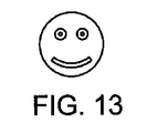
図13は、貫通孔によって形成された別個の形状を有するマーカーを図示する。例えば、マーカーが笑顔で現れる場合がある。貫通孔の大きさ及び形状を変更することによって互いに異なる形状が生成できる。 FIG. 13 illustrates a marker having discrete shapes formed by through holes. For example, the marker may appear with a smile. By changing the size and shape of the through holes, different shapes can be generated.
図14は、文字のような形状のマーカーを図示する。例えば、マーカーは大文字Aのような形状でもよい。他の文字形状のマーカーや特定の文字形状のマーカーは特定のマーカーを識別するために役立つ。 FIG. 14 illustrates a marker shaped like a character. For example, the marker may be shaped like a capital letter A. Other character-shaped markers or specific character-shaped markers help identify the specific marker.
図15は、数字のようなマーカーを図示する。例えば、マーカーは数字1の形状でもよい。他の数字形状のマーカー又は特定の数字形状のマーカーは特定のマーカーを識別するために役立つ。 FIG. 15 illustrates markers such as numbers. For example, the marker may be in the form of a number one. Other number shaped markers or specific number shaped markers serve to identify the particular marker.
図16は、貫通スロットを有する長方形のマーカーを図示する。 FIG. 16 illustrates a rectangular marker having a through slot.
図17は、貫通孔のパターンを有する長方形のマーカーを示す。 FIG. 17 shows a rectangular marker having a pattern of through holes.
図18は、刺付き矢印形状のマーカーを図示する。マーカーの突出部又は刺は他のアプローチ又は方向でイメージングされ得る表面を提供できる。 FIG. 18 illustrates a barbed arrow shaped marker. Markers overhangs or stings can provide a surface that can be imaged in other approaches or directions.
図19は、カプセルに含まれたマーカーを例示する。カプセルは生検腔(biospy cavity)で時間の経過によって吸収され得るゼラチンのような生体吸収性物質で形成されることができる。カプセルは第2生体吸収性物質に埋められた上述のマーカー20,40のようなマーカーを含むことができる。製造中において、カプセルは2つの半分が分離されることを防止するために均一な形状を有し得る。また、2つのカプセルの半分部をアルコール又は結合剤で共に固着させることができる。
FIG. 19 illustrates markers included in the capsule. Capsules can be formed of a bioabsorbable material, such as gelatin, that can be absorbed over time in a biopsy cavity. The capsule can include a marker such as the
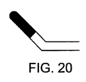
図20は、生検腔にマーカーを配置するためのマーカー及び予め曲げられたプッシュロッドを図示する。マーカーは予め曲げられたプッシュロッドの端部に形成された生体吸収性物質にカプセル化されることができる。図21に例示されたように、マーカー及び予め曲げられたプッシュロッドは、生検針を介して進むことができる。生検針の縦方向カニューレで、予め曲げられたプッシュロッドは真っすぐになることができる。図22に示すように、マーカーが生検針の孔に到達すると、予め曲げられたプッシュロッドは曲げられた形状に戻ってマーカーを保有する生体吸収性物質が生検針から突出できる。生検針を操作する医師は予め曲げられたプッシュロッドが曲げられた位置に戻ることを認知できる。プッシュロッドが曲げられた構成に戻る時、予め曲げられたプッシュロッドの縦方向運動は防止されることもできる。生検針のカッタはマーカーを含む生体吸収性物質のチップをせん断するために用いられることができる。 FIG. 20 illustrates a marker and a pre-bent push rod for placing the marker in a biopsy cavity. The marker can be encapsulated in a bioabsorbable material formed at the end of a pre-bent push rod. As illustrated in FIG. 21, the marker and the pre-bent push rod can be advanced through a biopsy needle. With the longitudinal cannula of the biopsy needle, the pre-bent pushrod can be straightened. As shown in FIG. 22, when the marker reaches the hole of the biopsy needle, the pre-bent push rod returns to the bent shape, and the bioabsorbable substance holding the marker can protrude from the biopsy needle. The physician operating the biopsy needle can recognize that the pre-bent push rod returns to the bent position. When the push rod returns to the bent configuration, longitudinal movement of the pre-bent push rod may be prevented. The biopsy needle cutter can be used to shear a tip of a bioabsorbable material including a marker.
図23は、予め曲げられたワイヤ展開器に取り付けられた他のマーカーを図示する。予め曲げられたワイヤはマーカーをカプセル化する生体吸収性物質に部分的に埋められ得る。図24に例示されたように、マーカーと予め曲げられたワイヤは生検針を介して進むことができる。生検針の縦方向カニューレで、予め曲げられたワイヤは、まっすぐになることができる。図25に示すように、マーカーが生検針の孔に到達すると、予め曲げられたワイヤは曲げられた形状に戻ってマーカーを保有する生体吸収性物質が生検針から突出できる。医師は生検針を操作しながら予め曲げられたワイヤが曲げられた構成に戻ることがわかる。ワイヤが曲げられた構成に戻る時、予め曲げられたワイヤの縦方向運動も防止され得る。予め曲げられたワイヤが近位に引っ張られる時、生体吸収性物質は生検針又はカッタの孔の縁を捕まるか、あるいはカプセル化されたマーカーがワイヤとともに収縮することを防止して生体吸収性物質からワイヤを除去できマーカーを生検腔に残す。 FIG. 23 illustrates another marker attached to a pre-bent wire deployer. The pre-bent wire can be partially embedded in a bioabsorbable material that encapsulates the marker. As illustrated in FIG. 24, the marker and the pre-bent wire can be advanced through a biopsy needle. With the longitudinal cannula of the biopsy needle, the pre-bent wire can be straightened. As shown in FIG. 25, when the marker reaches the hole in the biopsy needle, the pre-bent wire returns to the bent shape, and the bioabsorbable material carrying the marker can protrude from the biopsy needle. The physician knows that the pre-bent wire will return to the bent configuration while manipulating the biopsy needle. When the wire returns to the bent configuration, longitudinal movement of the pre-bent wire may also be prevented. When the pre-bent wire is pulled proximally, the bioabsorbable material can catch the edges of the biopsy needle or cutter hole or prevent the encapsulated marker from shrinking with the wire to prevent bioabsorbable material. The wire can be removed from the biopsy cavity, leaving the marker.
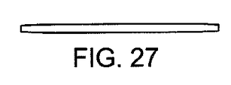
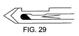
図27は、コラーゲンのような生体吸収性物質で形成された細長いマーカーを図示する。1つ以上の永久金属又はセラミックマーカーが細長いマーカーに挿入されることができる。図28に例示されたように、細長いマーカーはマーカー展開器を使用して展開されることができる。細長いマーカーはマーカー展開器内で曲げられることができる。図29に示すように、マーカー展開器は側面開口を有する生検針のカニューレを介して展開されることができる。細長いマーカーは、プッシュロッド(push rod)でマーカー展開器の末端部へ押されることができる。図30に例示されたように、細長いマーカーがマーカー展開器の外に押し出されると、まっすぐになることができる。まっすぐになった長いマーカーが生検針の側面開口に再度入ることは容易でない。 FIG. 27 illustrates an elongated marker formed of a bioabsorbable material such as collagen. One or more permanent metal or ceramic markers can be inserted into the elongated markers. As illustrated in FIG. 28, elongated markers can be deployed using a marker deployer. The elongated marker can be bent in the marker deployer. As shown in FIG. 29, the marker deployer can be deployed via a biopsy needle cannula having a side opening. The elongate marker can be pushed with a push rod to the distal end of the marker deployer. When the elongated marker is pushed out of the marker deployer, as illustrated in FIG. 30, it can straighten. It is not easy for a long straightened marker to re-enter the side opening of the biopsy needle.
図31は、ふさ(tassle)付きの球形マーカーを例示する。前記球はコラーゲンのような生体吸収性物質で製造されることができ、その中に埋められた永久マーカーを含むことができる。ふさは縫合材料で作ることができる。ふさ付きの球形のマーカーはふさが球に従うようにマーカー展開器を介して配置できる。図32で確認できるように、ふさ付きの球形のマーカーを生検腔に押し入れると、ふさが広がりマーカーの移動を減らすことができる。 FIG. 31 illustrates a spherical marker with a tassel. The sphere can be made of a bioabsorbable material such as collagen and can include a permanent marker embedded therein. The tuft can be made of suture material. A tufted spherical marker can be positioned via a marker deployer to follow the tuft. As can be seen in FIG. 32, pushing a spheroidal marker with a tuft into the biopsy cavity will widen the tuft and reduce the movement of the marker.
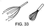
図33は、泡立て器形状のマーカーを示す。マーカーの分岐(tines)は配置中に共に維持されることができる。マーカーが配置されると分岐は広がることができる。この分岐はマーカーの移動を減らすために役立つことができ、マーカーのイメージ化可能領域を増加させることができる。 FIG. 33 shows a whisk-shaped marker. The markers tine can be maintained together during placement. When the marker is placed, the branch can expand. This bifurcation can help reduce marker movement and can increase the imageable area of the marker.
図34は、マーカーを囲む生体吸収性物質の形状を図示する。生体吸収性物質は、初期に長さに沿って1つ以上のX型セクションを有する円筒状に形成され得る。前記生体吸収性物質はマーカー展開器内に合うように圧縮されることができる。生体吸収性物質は生検腔内で膨脹できる。X型断面は移動を減少させてイメージ性能を向上させることができる。同じ質量を有する生体吸収性物質のシリンダに比べて、X字形の断面を有する生体吸収性物質はより大きな内接積体積(inscribed volume)を有し得る。 FIG. 34 illustrates the shape of the bioabsorbable material surrounding the marker. The bioabsorbable material may be initially formed into a cylinder having one or more X-shaped sections along its length. The bioabsorbable material can be compressed to fit within the marker deployer. The bioabsorbable material can expand in the biopsy cavity. The X-shaped cross section can reduce movement and improve image performance. As compared to a cylinder of bioabsorbable material having the same mass, a bioabsorbable material having an X-shaped cross-section may have a larger inscribed volume.
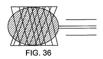
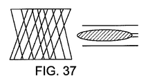
図35は、展開器内部のメッシュマーカーを図示する。メッシュマーカーは風船を使用して配置できる。図36に例示されたように、メッシュマーカーは生検針の終端をすぎて展開されることができ、風船は拡張されてメッシュマーカーを拡張させることができる。例えば、メッシュマーカーは生検腔の大きさに拡張されることができる。図37で説明したように、風船は収縮されると生検針を介して後に後退することができ、マーカーを残すことができる。 FIG. 35 illustrates a mesh marker inside the deployer. Mesh markers can be placed using balloons. As illustrated in FIG. 36, the mesh marker can be deployed past the end of the biopsy needle and the balloon can be expanded to expand the mesh marker. For example, a mesh marker can be expanded to the size of a biopsy cavity. As described in FIG. 37, when the balloon is deflated, it can be retracted back through the biopsy needle, leaving a marker.
図38は、らせん状マーカーを図示する。らせん状マーカーは生検針の末端部を介して展開され得る。図39に例示されたように、らせん状マーカーはらせん状マーカーを生検針の端部で組織内にねじ結合させることによって配置されることができる。マーカー展開器はプッシュロッドが展開器を介して移動する時、プッシュロッドが回転するようにねじ結合され得る。螺旋形マーカーは移動可能性がほぼない組織内で堅固に固定され得る。 FIG. 38 illustrates a helical marker. A helical marker can be deployed through the distal end of the biopsy needle. As illustrated in FIG. 39, the helical marker can be placed by screwing the helical marker into the tissue at the end of the biopsy needle. The marker deployer may be threadably coupled so that the pushrod rotates as the pushrod moves through the deployer. The helical marker can be firmly fixed in tissue with little mobility.
図40は、側面開口を有する生検針を介して配置されるコイルマーカーを図示する。コイルマーカーは広がる時、永久的に弾性力を有し変形されない材料で形成された緩いスプリングであり得る。例えば、コイルマーカーはチタニウムで形成され得る。コイルマーカーは生検針又はマーカー展開器の縦方向カニューレを介して広がるためまっすぐになることができる。コイルマーカーが生検腔に配置されると、コイルマーカーは図41と共にコイル型スプリング構成に戻ることができる。 FIG. 40 illustrates a coil marker positioned via a biopsy needle having a side opening. When unfolded, the coil marker may be a loose spring formed of a material that is permanently elastic and does not deform. For example, the coil marker can be formed of titanium. The coil marker can be straightened because it extends through the longitudinal cannula of the biopsy needle or marker deployer. When the coil marker is placed in the biopsy cavity, the coil marker can return to the coil spring configuration with FIG.
図42は、気泡を有するプラスチックマーカーを図示する。プラスチックマーカーは金属又はセラミックマーカーの周りに成形され得る。プラスチックマーカーが成形される時、気泡がプラスチックに誘導され得る。気泡はフィラーとしてガラスの球体を使用して形成されてもよい。気泡又はガラス球体は超音波イメージングのためのマーカーに密度差を作ることができる。 FIG. 42 illustrates a plastic marker with air bubbles. Plastic markers can be molded around metal or ceramic markers. When the plastic marker is molded, air bubbles can be induced in the plastic. Bubbles may be formed using glass spheres as fillers. Bubbles or glass spheres can create density differences in markers for ultrasound imaging.
図43は、球形スプリングマーカーを図示する。球形スプリングマーカーは平らに圧縮されて生体吸収性物質内に埋められ得る。球形スプリングマーカーはここに説明された配置装置及び技術のうち1つを使用して配置できる。生体吸収性物質は生検腔で吸収されることができ、球形スプリングマーカーは球形に戻ることができる。 FIG. 43 illustrates a spherical spring marker. The spherical spring marker can be compressed flat and embedded in the bioabsorbable material. The spherical spring marker can be positioned using one of the positioning devices and techniques described herein. The bioabsorbable material can be absorbed in the biopsy cavity and the spherical spring marker can return to a spherical shape.
図44は、ひだ付きマーカー展開器を図示する。ひだ付きマーカー展開器はマーカー展開器が縦に圧縮される時どのように変形されるかを予め決定するひだ、ノッチ又は弱い地点を含むことができる。例えば、ひだ付きマーカー展開器にはマーカーを固定するノッチとマーカーに隣接する2つのひだが含まれることができる。図45に示すように、ひだ付きマーカー展開器が生検装置の末端部に対抗して押されると、ひだ付きマーカー展開器はノッチ及びひだ付き部分で曲げられてマーカーが側面開口から側方向に排出されるようにすることができる。 FIG. 44 illustrates a pleated marker deployer. The pleated marker deployer can include folds, notches or weak spots that predetermine how the marker deployer is deformed when compressed vertically. For example, a pleated marker deployer can include a notch that secures the marker and two pleats adjacent the marker. As shown in FIG. 45, when the pleated marker deployer is pressed against the distal end of the biopsy device, the pleated marker deployer is bent at the notch and the pleated portion, causing the marker to move laterally from the side opening. Can be discharged.
図46A及び図46Bは、2つの形状部及び狭小部を有する平らなマーカーを図示する。それぞれの形状部はその外側に切開部を有する。一様態で、マーカーは長さが約0.1インチ、幅が0.037インチ及び厚さが0.006インチであり得る。マーカーの大きさはマーカーの材質によって異なる場合がある。例えば、チタニウムマーカーの寸法はステンレススチールマーカーに比べて大きく調整することができる。 46A and 46B illustrate a flat marker having two features and a narrowing. Each profile has an incision on its outside. In one aspect, the marker can be about 0.1 inches long, 0.037 inches wide and 0.006 inches thick. The size of the marker may vary depending on the material of the marker. For example, the dimensions of a titanium marker can be adjusted to be larger than a stainless steel marker.
図47A及び47Bは、2つの形状部及び狭小部を有する捩れたマーカーを図示する。それぞれの形状部はD字の形状を有し、文字Dのような形状の貫通孔を含む。一様態で、マーカーは長さが約0.1インチ、幅が0.037インチ及び厚さが0.007インチであり得る。 FIGS. 47A and 47B illustrate a twisted marker having two features and a constriction. Each shape has a D-shape and includes a through-hole shaped like the letter D. In one aspect, the markers can be about 0.1 inches long, 0.037 inches wide and 0.007 inches thick.
図48A及び48Bは、貫通孔を有する平らなマーカーを図示する。一特徴として、マーカーは長い楕円形の形状を有し得る。それぞれの貫通孔は広い文字Dのような形状であり得る。マーカーは長さが約0.1インチ、幅が0.037インチ及び厚さが0.007インチであり得る。 48A and 48B illustrate a flat marker having a through hole. In one aspect, the marker can have a long elliptical shape. Each through hole may be shaped like a wide letter D. The markers may be about 0.1 inches long, 0.037 inches wide and 0.007 inches thick.
図49A及び49Bは、3つの貫通孔を有する平らなマーカーを図示する。マーカーは長さが約0.16インチ、幅が0.37インチ及び厚さが0.007インチである長い楕円形でもよい。貫通孔は台形のような他の形状でもよい。ブリッジング部は貫通孔の間で延長された側面を連結させることができる。ブリッジング部は斜めであっても直線であってもよい。 49A and 49B illustrate a flat marker having three through holes. The marker may be a long ellipse approximately 0.16 inches long, 0.37 inches wide and 0.007 inches thick. The through hole may have another shape such as a trapezoid. The bridging part may connect the extended side surfaces between the through holes. The bridging portion may be oblique or straight.
図50A及び50Bは、狭小部のない捩れたマーカーを図示する。代わりに、捩れたマーカーは長い楕円形の平面マーカーに形成され得る。捩じるとマーカーの長い面が曲がることができる。マーカーは長さが約0.12インチ、幅が0.037インチ、厚さが0.007インチであり得る。 FIGS. 50A and 50B illustrate a twisted marker without a narrowing. Alternatively, the twisted marker can be formed into a long elliptical planar marker. When twisted, the long side of the marker can bend. The marker may be about 0.12 inches long, 0.037 inches wide, and 0.007 inches thick.
図51A及び51Bは、2つの形状部及び狭小部を有する平らなマーカーを図示する。前記形状部は外側に広がり中央に向かって狭くなることができる。前記形状部は類似した形状の貫通孔を含むことができる。一様態で、マーカーは長さが約0.1インチ、幅が0.026インチ及び厚さが0.007インチであり得る。 FIGS. 51A and 51B illustrate a flat marker having two features and a constriction. The shape may extend outward and narrow toward the center. The shape portion may include a through hole having a similar shape. In one aspect, the markers can be about 0.1 inches long, 0.026 inches wide and 0.007 inches thick.
図52A及び52Bは、2つの形状部及び狭小部を有する平らなマーカーを図示する。それぞれの形状部は長く複数の貫通孔を含むことができる。一様態で、マーカーは長さが約0.13インチ、幅が0.026インチ及び厚さが0.007インチであり得る。 FIGS. 52A and 52B illustrate a flat marker having two features and a constriction. Each shape may be long and include a plurality of through holes. In one aspect, the markers can be about 0.13 inches long, 0.026 inches wide and 0.007 inches thick.
図53A乃至53Eは、3つの形状部502a−502c及び2つの狭小部504a及び502bを有する捩れたマーカー500の多様な図面を図示する。捩れたマーカー500は、捩れたマーカー20(図2A)と同じでよい。それぞれの形状部502は、丸い四角形で形成されてもよい。貫通孔506は丸い長方形に形成されてもよい。図53Eに図示されたように、それぞれの形状部の間の角度は約45度でもよい。すなわち、形状部502aの表面と形状部502bの表面の間の角度は45度でもよく、形状部502bの表面と形状部502cの表面の間の角度は45度でもよい。他の様態で、マーカー500は捩じれて各形状部502の間の角度が約30度になることができる。
53A-53E illustrate various views of a
図54A乃至54Eは、3つの形状部512及び2つの狭小部514を有する捩れたマーカー510の多様な図面を図示する。捩れたマーカー510は、捩れたマーカー20(図2A)と同じでよい。それぞれの形状部512は、丸い四角形に形成され得る。貫通孔516は円形でもよい。図54Eに示すように、それぞれの形状部の表面間の角度は約60度でもよい。すなわち、形状部512aの表面と形状部512bの表面の間の角度は60度でもよく、形状部512bの表面と形状部512cの表面の間の角度は60度でもよい。3つの形状部を有するマーカーに対して、60度の角は平らな表面のそれぞれが他の表面から同じ角度で捩じれるようにすることができる。すなわち、前記形状部512aの表面は前記形状部512cの表面に対して60度の角度を有し得る。かかる配置は軸に対して横断する任意の角度から形状部の表面の一部を提供できる。
54A-54E illustrate various views of a twisted marker 510 having three features 512 and two narrows 514. FIG. Twisted marker 510 may be the same as twisted marker 20 (FIG. 2A). Each shape part 512 may be formed in a round square. The through hole 516 may be circular. As shown in FIG. 54E, the angle between the surfaces of each feature may be about 60 degrees. That is, the angle between the surface of the
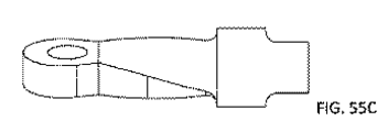
図55A乃至55Eは、2つの互いに異なる形状部及び延長された狭小部を有する捩れたマーカーの多様な図面を図示する。例えば、第1形状部は円形でもよい。第1形状部は貫通孔を含むことができる。第2形状部は十字型又はプラス符号形状のであり得る。延長された狭小部は捩れることができる。一様態で、延長された狭小部は捩れる応力を減少させることができ、例えば、マーカーを囲む生体吸収性物質が圧縮される時に損傷に対する強度を提供できる。 FIGS. 55A-55E illustrate various views of a twisted marker having two different shapes and an elongated constriction. For example, the first shape portion may be circular. The first shape part may include a through hole. The second shape may be cross-shaped or a plus sign shape. The elongated constriction can be twisted. In one aspect, the elongated constriction can reduce torsional stress, for example, providing strength against damage when the bioabsorbable material surrounding the marker is compressed.
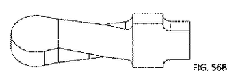
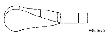
図56A乃至56Eは、捩れたマーカーが貫通孔を含まないことを除いては図55A乃至55Eのマーカーと類似した捩れたマーカーの多様な図面を図示する。 FIGS. 56A-56E illustrate various views of a twisted marker similar to the markers of FIGS. 55A-55E except that the twisted marker does not include a through hole.
図57A乃至57Eは、3つの形状部及び2つの捩じれた部分を有する捩れたマーカーの多様な図面を図示する。形状部は互いに異なる形状を有し得る。例えば、図示のように、外部形状部は十字型又はプラス符号のような形状でもよく、中間形状部はハートのような形状でもよい。ハート形状は狭小部に連結されるように修正できる。それぞれの形状部は貫通孔(図示せず)を含むこともできる。 57A-57E illustrate various views of a twisted marker having three features and two twisted portions. The shapes may have different shapes from each other. For example, as shown, the external shape may be shaped like a cross or a plus sign, and the intermediate shape may be shaped like a heart. The heart shape can be modified to connect to the constriction. Each shape may include a through hole (not shown).
図58A乃至58Cは、3つの形状部及び2つの捩じれた部分を有する捩じれたマーカー多様な図面を図示する。外形部分は図57と類似した形状、すなわち十字型又はプラス符号のような形状でもよい。中央の形状部は長方形でもよい。狭小部はそれぞれ約60度まで捩じれてもよい。 58A-58C illustrate various views of a twisted marker having three features and two twisted portions. The outer portion may have a shape similar to that of FIG. 57, that is, a shape like a cross or a plus sign. The central shape may be rectangular. The constrictions may each be twisted up to about 60 degrees.
図59A乃至59Dは、マーカーの多様な図面を図示する。マーカーは形状部、捩れた部分及びローリング(rolled)部分を有し得る。形状部は本明細書で論じられた任意の形状であり得る。例えば、図59Aに示すように、形状部は長方形でもよい。形状部は1つ以上の貫通孔を含むことができる。ローリング部は1つ以上の寸法で曲げられるか又はローリング(rolled)され得る。一様態で、ローリング部は、ローリングされるか曲げられた平らな部分に形成され得る。例えば、図59A乃至59Dに示すように、ローリング部は長方形の平らな形状部に形成され得る。一様態で、図59A乃至59Dのマーカーに対するマーカーブランクは初期にはT字型でもよく、Tの上部は各側面から内側にローリングされることができる。ローリング部は、1つ以上の貫通孔を含むこともできる。図示のように、例えば、図59Dに示すように、ローリング部のそれぞれの側面上の貫通孔が整列されることができる。ローリング部の両側面は、例えば、マーカーの中心軸に沿って会うことができる。捩れた部分は形状部とローリング部を連結させることができる。一様態で、捩れた部分の1つ以上の下位部分は互いに異なる方向に捩れる場合がある。例えば、捩れた部分の一側上のサブ−部分は一方向に捩じれ、捩れた部分の他の側上のサブ−部分は反対方向に捩じれ得る。一特徴として、前記マーカーは捩じれない連結部分を含んだり、前記形状部は前記ローリング部と連続的に形成され得る。 59A-59D illustrate various views of the marker. The marker may have a shape, a twisted portion and a rolled portion. The features can be any of the shapes discussed herein. For example, as shown in FIG. 59A, the shape portion may be rectangular. The features may include one or more through holes. The rolling portion may be bent or rolled in one or more dimensions. In one aspect, the rolling portion may be formed into a flat portion that is rolled or bent. For example, as shown in FIGS. 59A to 59D, the rolling portion may be formed in a rectangular flat shape. In one aspect, the marker blank for the markers of FIGS. 59A-59D may initially be T-shaped, with the top of T being rolled in from each side. The rolling portion can also include one or more through holes. As shown, for example, as shown in FIG. 59D, the through holes on each side of the rolling portion can be aligned. Both sides of the rolling part can meet, for example, along the central axis of the marker. The twisted part can connect the shape part and the rolling part. In one aspect, one or more sub-portions of the twisted portion may twist in different directions from each other. For example, a sub-portion on one side of the twisted portion may be twisted in one direction and a sub-portion on the other side of the twisted portion may be twisted in the opposite direction. In one aspect, the marker may include a non-twisting connection portion, or the shape portion may be formed continuously with the rolling portion.
前述した説明は例示的な態様及び/又は実施例を説明しているが、添付された請求範囲によって定義されたような説明された様態及び/又は実施例の範囲から逸脱することなく多様な変更及び修正が行なわれることができることを理解するべきである。また、説明された様態及び/又は実施例の要素が単数形で記述されたり請求され得るが、単数への制限が明示的に言及されない限り、複数形が考慮される。また、任意の様態及び/又は実施例の全部又は一部は他の言及がない限り、任意の他の態様及び/又は実施例の全部又は一部とともに用いられ得る。
While the foregoing description illustrates exemplary aspects and / or embodiments, various changes may be made without departing from the scope of the described aspects and / or embodiments as defined by the appended claims. And that modifications can be made. Also, elements of the described aspects and / or embodiments may be described or claimed in the singular, but the plural is contemplated unless limitation to the singular is explicitly stated. Also, all or part of any aspect and / or example may be used with all or part of any other aspect and / or example, unless stated otherwise.
Claims (13)
軸に沿って順に配列された第1形状部、第2形状部及び第3形状部を含み、
前記第1形状部、前記第2形状部及び前記第3形状部は、それぞれ、平らな第1表面を有し、
前記第1形状部の前記平らな第1表面は、前記第2形状部の前記平らな第1表面に対して選択された第1角度で配置され、
前記第2形状部の前記平らな第1表面は、前記第3形状部の前記平らな第1表面に対して選択された第2角度で配置され、
前記第1形状部の前記平らな第1表面は、前記第3形状部の前記平らな第1表面に対して選択された第3角度で配置される、
生検マーカー。 A biopsy marker,
A first shape portion, a second shape portion, and a third shape portion arranged in order along the axis ;
The first shape portion, the second shape portion, and the third shape portion each have a flat first surface,
Wherein the planar first surface of the first shaped portion is disposed at a first angle of which is selected for the flat first surface of the second shaped portion,
The flat first surface of the second shape is disposed at a selected second angle with respect to the flat first surface of the third shape ;
The flat first surface of the first shape is disposed at a selected third angle with respect to the flat first surface of the third shape;
Biopsy marker.
前記第2形状部を前記第3形状部と連結する第2狭小部をさらに含む請求項1に記載の生検マーカー。 The biopsy marker according to claim 1, further comprising: a first narrow portion connecting the first shape portion to the second shape portion; and a second narrow portion connecting the second shape portion to the third shape portion. .
軸に沿って順に配列された第1形状部、第2形状部及び第3形状部を含み、それぞれの形状部は第1表面を有し;
前記第1形状部の前記第1表面が前記第2形状部の前記第1表面に対して選択された第1角度で配置されるように前記軸を中心に前記第1形状部を捩じるステップ;及び
生検マーカーを形成するために、前記第2形状部の前記第1表面が前記第3形状部の前記第1表面に対して選択された第2角度で配置されるように、且つ、前記第3形状部の前記第1表面が前記第1形状部の前記第1表面に対して選択された第3角度で配置されるように、前記軸を中心に前記第3形状部を捩じるステップを含む、
生検マーカー製造方法。 Stamping a marker blank from a flat metal sheet, the marker blank comprising:
A first shape, a second shape, and a third shape arranged in order along the axis, each shape having a first surface;
Twisting the first shape portion about the axis such that the first surface of the first shape portion is disposed at a selected first angle with respect to the first surface of the second shape portion. Steps; and
The first surface of the second shape is positioned at a selected second angle with respect to the first surface of the third shape to form a biopsy marker ; and Twisting the third profile about the axis such that the first surface of the three profile is disposed at a selected third angle with respect to the first surface of the first profile. including,
Biopsy marker manufacturing method.
前記生検マーカーの周りで生体吸収性物質を圧縮するステップをさらに含む請求項11に記載の生検マーカー製造方法。 12. The method of claim 11, further comprising: encapsulating the biopsy marker in a bioabsorbable material; and compressing the bioabsorbable material around the biopsy marker.
前記第1形状部を前記第2形状部と連結する第1狭小部;及び
前記第2形状部を前記第3形状部と連結する第2狭小部をさらに含む請求項11に記載の生検マーカー製造方法。 The marker blank is
The biopsy marker according to claim 11, further comprising: a first narrow portion connecting the first shape portion to the second shape portion; and a second narrow portion connecting the second shape portion to the third shape portion. Production method.
Applications Claiming Priority (3)
| Application Number | Priority Date | Filing Date | Title |
|---|---|---|---|
| US201462061586P | 2014-10-08 | 2014-10-08 | |
| US62/061,586 | 2014-10-08 | ||
| PCT/US2015/054679 WO2016057785A1 (en) | 2014-10-08 | 2015-10-08 | Biopsy marker |
Related Child Applications (1)
| Application Number | Title | Priority Date | Filing Date |
|---|---|---|---|
| JP2020030882A Division JP7053698B2 (en) | 2014-10-08 | 2020-02-26 | Marking device and marker delivery device |
Publications (3)
| Publication Number | Publication Date |
|---|---|
| JP2017534370A JP2017534370A (en) | 2017-11-24 |
| JP2017534370A5 JP2017534370A5 (en) | 2018-11-08 |
| JP6668339B2 true JP6668339B2 (en) | 2020-03-18 |
Family
ID=54361168
Family Applications (4)
| Application Number | Title | Priority Date | Filing Date |
|---|---|---|---|
| JP2017519308A Active JP6668339B2 (en) | 2014-10-08 | 2015-10-08 | Biopsy marker and method for producing biopsy marker |
| JP2020030882A Active JP7053698B2 (en) | 2014-10-08 | 2020-02-26 | Marking device and marker delivery device |
| JP2022058961A Active JP7465904B2 (en) | 2014-10-08 | 2022-03-31 | Biopsy site marker |
| JP2024058742A Pending JP2024074877A (en) | 2014-10-08 | 2024-04-01 | Biopsy site marker |
Family Applications After (3)
| Application Number | Title | Priority Date | Filing Date |
|---|---|---|---|
| JP2020030882A Active JP7053698B2 (en) | 2014-10-08 | 2020-02-26 | Marking device and marker delivery device |
| JP2022058961A Active JP7465904B2 (en) | 2014-10-08 | 2022-03-31 | Biopsy site marker |
| JP2024058742A Pending JP2024074877A (en) | 2014-10-08 | 2024-04-01 | Biopsy site marker |
Country Status (6)
| Country | Link |
|---|---|
| US (3) | US10492884B2 (en) |
| EP (1) | EP3203925B1 (en) |
| JP (4) | JP6668339B2 (en) |
| KR (1) | KR20170087866A (en) |
| CN (2) | CN106794049A (en) |
| WO (1) | WO2016057785A1 (en) |
Families Citing this family (9)
| Publication number | Priority date | Publication date | Assignee | Title |
|---|---|---|---|---|
| CN106794049A (en) | 2014-10-08 | 2017-05-31 | Devicor医疗产业收购公司 | Biopsy marker |
| KR102411111B1 (en) * | 2016-05-31 | 2022-06-20 | 코닝 인코포레이티드 | Glass Articles Exhibiting Improved Fracture Performance |
| CN111465351A (en) | 2017-12-11 | 2020-07-28 | 豪洛捷公司 | Ultrasonic localization system with advanced biopsy site markers |
| JP7463407B2 (en) | 2019-05-30 | 2024-04-08 | デビコー・メディカル・プロダクツ・インコーポレイテッド | Biopsy site marker for limited mobility |
| US20220160457A1 (en) * | 2020-10-27 | 2022-05-26 | Wake Forest University Health Sciences | Biopsy device marker and related methods |
| WO2022225733A1 (en) * | 2021-04-19 | 2022-10-27 | Medstar Health, Inc. | Areola marker placement guide |
| WO2023249760A1 (en) * | 2022-06-23 | 2023-12-28 | Devicor Medical Products, Inc. | Biopsy site marker with expandable mesh |
| WO2024118097A1 (en) * | 2022-11-30 | 2024-06-06 | Bard Peripheral Vascular, Inc. | Biopsy device with integrated marker |
| JP7562090B1 (en) | 2023-10-19 | 2024-10-07 | 国立大学法人高知大学 | Marker, marker placement device, and marker detection device |
Family Cites Families (58)
| Publication number | Priority date | Publication date | Assignee | Title |
|---|---|---|---|---|
| US5526822A (en) | 1994-03-24 | 1996-06-18 | Biopsys Medical, Inc. | Method and apparatus for automated biopsy and collection of soft tissue |
| EP0781114B1 (en) * | 1994-09-16 | 2005-05-25 | Ethicon Endo-Surgery, Inc. | Devices for defining and marking tissue |
| CN2212392Y (en) * | 1995-01-20 | 1995-11-15 | 李继明 | Colon transporting test marker with multiple geometric shapes |
| NO962336L (en) * | 1995-06-06 | 1996-12-09 | Target Therapeutics Inc | Vaso-occlusive spiral |
| US6017316A (en) | 1997-06-18 | 2000-01-25 | Biopsys Medical | Vacuum control system and method for automated biopsy device |
| US6056700A (en) * | 1998-10-13 | 2000-05-02 | Emx, Inc. | Biopsy marker assembly and method of use |
| US6220248B1 (en) * | 1998-10-21 | 2001-04-24 | Ethicon Endo-Surgery, Inc. | Method for implanting a biopsy marker |
| US6371904B1 (en) * | 1998-12-24 | 2002-04-16 | Vivant Medical, Inc. | Subcutaneous cavity marking device and method |
| US20090216118A1 (en) | 2007-07-26 | 2009-08-27 | Senorx, Inc. | Polysaccharide markers |
| US6086544A (en) | 1999-03-31 | 2000-07-11 | Ethicon Endo-Surgery, Inc. | Control apparatus for an automated surgical biopsy device |
| US6162187A (en) | 1999-08-02 | 2000-12-19 | Ethicon Endo-Surgery, Inc. | Fluid collection apparatus for a surgical device |
| US6428487B1 (en) | 1999-12-17 | 2002-08-06 | Ethicon Endo-Surgery, Inc. | Surgical biopsy system with remote control for selecting an operational mode |
| US6432065B1 (en) | 1999-12-17 | 2002-08-13 | Ethicon Endo-Surgery, Inc. | Method for using a surgical biopsy system with remote control for selecting and operational mode |
| US6350244B1 (en) * | 2000-02-21 | 2002-02-26 | Biopsy Sciences, Llc | Bioabsorable markers for use in biopsy procedures |
| US6602203B2 (en) | 2000-10-13 | 2003-08-05 | Ethicon Endo-Surgery, Inc. | Remote thumbwheel for a surgical biopsy device |
| US6605047B2 (en) * | 2001-09-10 | 2003-08-12 | Vivant Medical, Inc. | Biopsy marker delivery system |
| US6626849B2 (en) | 2001-11-01 | 2003-09-30 | Ethicon Endo-Surgery, Inc. | MRI compatible surgical biopsy device |
| CA2479349C (en) * | 2002-03-19 | 2012-07-03 | Bard Dublin Itc Limited | Biopsy device and biopsy needle module that can be inserted into the biopsy device |
| US7744852B2 (en) * | 2003-07-25 | 2010-06-29 | Rubicor Medical, Llc | Methods and systems for marking post biopsy cavity sites |
| US7465279B2 (en) | 2004-03-31 | 2008-12-16 | Ethicon Endo-Surgery, Inc. | Marker device and method of deploying a cavity marker using a surgical biopsy device |
| US8075568B2 (en) * | 2004-06-11 | 2011-12-13 | Selis James E | Biopsy devices and methods |
| US20060074345A1 (en) | 2004-09-29 | 2006-04-06 | Hibner John A | Biopsy apparatus and method |
| US8280486B2 (en) | 2004-10-13 | 2012-10-02 | Suros Surgical Systems, Inc. | Site marker visable under multiple modalities |
| US20060247678A1 (en) * | 2005-04-08 | 2006-11-02 | Weisenburgh William B Ii | Surgical instrument system |
| US7854707B2 (en) | 2005-08-05 | 2010-12-21 | Devicor Medical Products, Inc. | Tissue sample revolver drum biopsy device |
| ES2539578T3 (en) | 2005-08-10 | 2015-07-02 | C.R. Bard, Inc. | Multi-sample biopsy device and single insert with various transport systems |
| US7761137B2 (en) | 2005-12-16 | 2010-07-20 | Suros Surgical Systems, Inc. | Biopsy site marker deployment device |
| US8702623B2 (en) | 2008-12-18 | 2014-04-22 | Devicor Medical Products, Inc. | Biopsy device with discrete tissue chambers |
| US20130324882A1 (en) | 2012-05-30 | 2013-12-05 | Devicor Medical Products, Inc. | Control for biopsy device |
| US9345457B2 (en) | 2006-12-13 | 2016-05-24 | Devicor Medical Products, Inc. | Presentation of biopsy sample by biopsy device |
| US7938786B2 (en) | 2006-12-13 | 2011-05-10 | Devicor Medical Products, Inc. | Vacuum timing algorithm for biopsy device |
| ES2432572T3 (en) | 2006-12-18 | 2013-12-04 | C.R. Bard, Inc. | Biopsy marker with imaging properties generated in situ |
| EP2180842A1 (en) * | 2007-08-27 | 2010-05-05 | Spine View, Inc. | Balloon cannula system for accessing and visualizing spine and related methods |
| US8454531B2 (en) | 2007-11-20 | 2013-06-04 | Devicor Medical Products, Inc. | Icon-based user interface on biopsy system control module |
| US20090131821A1 (en) | 2007-11-20 | 2009-05-21 | Speeg Trevor W V | Graphical User Interface For Biopsy System Control Module |
| US7854706B2 (en) | 2007-12-27 | 2010-12-21 | Devicor Medical Products, Inc. | Clutch and valving system for tetherless biopsy device |
| WO2009099767A2 (en) * | 2008-01-31 | 2009-08-13 | C.R. Bard, Inc. | Biopsy tissue marker |
| US8622924B2 (en) | 2008-02-27 | 2014-01-07 | Devicor Medical Products, Inc. | Needle tip for biopsy device |
| US8532747B2 (en) * | 2008-08-22 | 2013-09-10 | Devicor Medical Products, Inc. | Biopsy marker delivery device |
| US20100152610A1 (en) | 2008-12-16 | 2010-06-17 | Parihar Shailendra K | Hand Actuated Tetherless Biopsy Device with Pistol Grip |
| US8083687B2 (en) | 2008-12-18 | 2011-12-27 | Devicor Medical Products, Inc. | Tissue biopsy device with rotatably linked thumbwheel and tissue sample holder |
| US20100160819A1 (en) | 2008-12-18 | 2010-06-24 | Parihar Shailendra K | Biopsy Device with Central Thumbwheel |
| CN105380650A (en) * | 2009-01-06 | 2016-03-09 | 普罗秋斯数字健康公司 | High-throughput production of ingestible event markers |
| US8206316B2 (en) | 2009-06-12 | 2012-06-26 | Devicor Medical Products, Inc. | Tetherless biopsy device with reusable portion |
| EP3847959B1 (en) * | 2009-06-26 | 2024-09-11 | Cianna Medical, Inc. | System for localizing markers or tissue structures within a body |
| US20110028831A1 (en) * | 2009-07-30 | 2011-02-03 | Kent James P | Permanently visible implantable fiduciary tissue marker |
| US8529465B2 (en) * | 2009-09-24 | 2013-09-10 | Devicor Medical Products, Inc. | Biopsy marker delivery devices and methods |
| US20110218433A1 (en) * | 2010-03-02 | 2011-09-08 | Speeg Trevor W V | Biopsy Marker Delivery Device |
| US8764680B2 (en) | 2010-11-01 | 2014-07-01 | Devicor Medical Products, Inc. | Handheld biopsy device with needle firing |
| US8858465B2 (en) | 2011-04-14 | 2014-10-14 | Devicor Medical Products, Inc. | Biopsy device with motorized needle firing |
| US8801742B2 (en) | 2011-06-01 | 2014-08-12 | Devicor Medical Products, Inc. | Needle assembly and blade assembly for biopsy device |
| US8938285B2 (en) | 2011-08-08 | 2015-01-20 | Devicor Medical Products, Inc. | Access chamber and markers for biopsy device |
| US9326755B2 (en) | 2011-08-26 | 2016-05-03 | Devicor Medical Products, Inc. | Biopsy device tissue sample holder with bulk chamber and pathology chamber |
| US8798716B1 (en) * | 2011-11-03 | 2014-08-05 | Solstice Corporation | Fiducial markers and related methods |
| JP2014030555A (en) * | 2012-08-02 | 2014-02-20 | Terumo Corp | Medical instrument |
| CN103961802A (en) * | 2013-01-28 | 2014-08-06 | 刘苗生 | Self-deforming metal marker |
| AU2014290446A1 (en) * | 2013-07-19 | 2016-01-28 | Devicor Medical Products, Inc. | Biopsy device targeting features |
| CN106794049A (en) | 2014-10-08 | 2017-05-31 | Devicor医疗产业收购公司 | Biopsy marker |
-
2015
- 2015-10-08 CN CN201580055072.9A patent/CN106794049A/en active Pending
- 2015-10-08 EP EP15787352.2A patent/EP3203925B1/en active Active
- 2015-10-08 CN CN202210050925.1A patent/CN114376739A/en active Pending
- 2015-10-08 JP JP2017519308A patent/JP6668339B2/en active Active
- 2015-10-08 KR KR1020177011801A patent/KR20170087866A/en unknown
- 2015-10-08 WO PCT/US2015/054679 patent/WO2016057785A1/en active Application Filing
-
2017
- 2017-04-04 US US15/478,929 patent/US10492884B2/en active Active
-
2019
- 2019-10-30 US US16/668,610 patent/US11123151B2/en active Active
-
2020
- 2020-02-26 JP JP2020030882A patent/JP7053698B2/en active Active
-
2021
- 2021-08-24 US US17/409,879 patent/US12102491B2/en active Active
-
2022
- 2022-03-31 JP JP2022058961A patent/JP7465904B2/en active Active
-
2024
- 2024-04-01 JP JP2024058742A patent/JP2024074877A/en active Pending
Also Published As
| Publication number | Publication date |
|---|---|
| US12102491B2 (en) | 2024-10-01 |
| CN106794049A (en) | 2017-05-31 |
| JP7465904B2 (en) | 2024-04-11 |
| US20220008160A1 (en) | 2022-01-13 |
| KR20170087866A (en) | 2017-07-31 |
| JP7053698B2 (en) | 2022-04-12 |
| EP3203925A1 (en) | 2017-08-16 |
| WO2016057785A1 (en) | 2016-04-14 |
| EP3203925B1 (en) | 2024-03-13 |
| US20200060787A1 (en) | 2020-02-27 |
| US11123151B2 (en) | 2021-09-21 |
| JP2022084923A (en) | 2022-06-07 |
| US10492884B2 (en) | 2019-12-03 |
| JP2017534370A (en) | 2017-11-24 |
| JP2024074877A (en) | 2024-05-31 |
| US20170202635A1 (en) | 2017-07-20 |
| JP2020078628A (en) | 2020-05-28 |
| CN114376739A (en) | 2022-04-22 |
Similar Documents
| Publication | Publication Date | Title |
|---|---|---|
| JP6668339B2 (en) | Biopsy marker and method for producing biopsy marker | |
| US11779432B2 (en) | Marking device and implantation system | |
| EP3171820B1 (en) | Implantable devices and techniques for oncoplastic surgery | |
| US8280486B2 (en) | Site marker visable under multiple modalities | |
| US20090000629A1 (en) | Elastically Deformable Marker | |
| US20060079805A1 (en) | Site marker visable under multiple modalities | |
| CN105007864B (en) | Monofilament implants and systems for delivery thereof | |
| US12004911B2 (en) | Biopsy site marker for limited migration | |
| US20220241048A1 (en) | Implantable Marker | |
| JP2023505114A (en) | Marker element for marking tissue | |
| CA3225433A1 (en) | Implantable marker | |
| TWM437178U (en) | Improved expanding device for implant of minimally invasive surgery |
Legal Events
| Date | Code | Title | Description |
|---|---|---|---|
| A521 | Request for written amendment filed |
Free format text: JAPANESE INTERMEDIATE CODE: A523 Effective date: 20180925 |
|
| A621 | Written request for application examination |
Free format text: JAPANESE INTERMEDIATE CODE: A621 Effective date: 20180925 |
|
| A131 | Notification of reasons for refusal |
Free format text: JAPANESE INTERMEDIATE CODE: A131 Effective date: 20190702 |
|
| A977 | Report on retrieval |
Free format text: JAPANESE INTERMEDIATE CODE: A971007 Effective date: 20190628 |
|
| A521 | Request for written amendment filed |
Free format text: JAPANESE INTERMEDIATE CODE: A523 Effective date: 20191002 |
|
| TRDD | Decision of grant or rejection written | ||
| A01 | Written decision to grant a patent or to grant a registration (utility model) |
Free format text: JAPANESE INTERMEDIATE CODE: A01 Effective date: 20200128 |
|
| A61 | First payment of annual fees (during grant procedure) |
Free format text: JAPANESE INTERMEDIATE CODE: A61 Effective date: 20200226 |
|
| R150 | Certificate of patent or registration of utility model |
Ref document number: 6668339 Country of ref document: JP Free format text: JAPANESE INTERMEDIATE CODE: R150 |
|
| R250 | Receipt of annual fees |
Free format text: JAPANESE INTERMEDIATE CODE: R250 |
|
| R250 | Receipt of annual fees |
Free format text: JAPANESE INTERMEDIATE CODE: R250 |


