CN114376739A - Biopsy markers - Google Patents
Biopsy markers Download PDFInfo
- Publication number
- CN114376739A CN114376739A CN202210050925.1A CN202210050925A CN114376739A CN 114376739 A CN114376739 A CN 114376739A CN 202210050925 A CN202210050925 A CN 202210050925A CN 114376739 A CN114376739 A CN 114376739A
- Authority
- CN
- China
- Prior art keywords
- marker
- biopsy
- forming portion
- shaped
- twisted
- Prior art date
- Legal status (The legal status is an assumption and is not a legal conclusion. Google has not performed a legal analysis and makes no representation as to the accuracy of the status listed.)
- Pending
Links
Images


Classifications
-
- A—HUMAN NECESSITIES
- A61—MEDICAL OR VETERINARY SCIENCE; HYGIENE
- A61B—DIAGNOSIS; SURGERY; IDENTIFICATION
- A61B10/00—Other methods or instruments for diagnosis, e.g. instruments for taking a cell sample, for biopsy, for vaccination diagnosis; Sex determination; Ovulation-period determination; Throat striking implements
- A61B10/02—Instruments for taking cell samples or for biopsy
- A61B10/0233—Pointed or sharp biopsy instruments
- A61B10/0266—Pointed or sharp biopsy instruments means for severing sample
- A61B10/0275—Pointed or sharp biopsy instruments means for severing sample with sample notch, e.g. on the side of inner stylet
-
- A—HUMAN NECESSITIES
- A61—MEDICAL OR VETERINARY SCIENCE; HYGIENE
- A61B—DIAGNOSIS; SURGERY; IDENTIFICATION
- A61B90/00—Instruments, implements or accessories specially adapted for surgery or diagnosis and not covered by any of the groups A61B1/00 - A61B50/00, e.g. for luxation treatment or for protecting wound edges
- A61B90/39—Markers, e.g. radio-opaque or breast lesions markers
-
- A—HUMAN NECESSITIES
- A61—MEDICAL OR VETERINARY SCIENCE; HYGIENE
- A61B—DIAGNOSIS; SURGERY; IDENTIFICATION
- A61B17/00—Surgical instruments, devices or methods, e.g. tourniquets
- A61B2017/00004—(bio)absorbable, (bio)resorbable, resorptive
-
- A—HUMAN NECESSITIES
- A61—MEDICAL OR VETERINARY SCIENCE; HYGIENE
- A61B—DIAGNOSIS; SURGERY; IDENTIFICATION
- A61B17/00—Surgical instruments, devices or methods, e.g. tourniquets
- A61B2017/00831—Material properties
- A61B2017/0088—Material properties ceramic
-
- A—HUMAN NECESSITIES
- A61—MEDICAL OR VETERINARY SCIENCE; HYGIENE
- A61B—DIAGNOSIS; SURGERY; IDENTIFICATION
- A61B17/00—Surgical instruments, devices or methods, e.g. tourniquets
- A61B2017/00831—Material properties
- A61B2017/00898—Material properties expandable upon contact with fluid
-
- A—HUMAN NECESSITIES
- A61—MEDICAL OR VETERINARY SCIENCE; HYGIENE
- A61B—DIAGNOSIS; SURGERY; IDENTIFICATION
- A61B90/00—Instruments, implements or accessories specially adapted for surgery or diagnosis and not covered by any of the groups A61B1/00 - A61B50/00, e.g. for luxation treatment or for protecting wound edges
- A61B90/39—Markers, e.g. radio-opaque or breast lesions markers
- A61B2090/3904—Markers, e.g. radio-opaque or breast lesions markers specially adapted for marking specified tissue
- A61B2090/3908—Soft tissue, e.g. breast tissue
-
- A—HUMAN NECESSITIES
- A61—MEDICAL OR VETERINARY SCIENCE; HYGIENE
- A61B—DIAGNOSIS; SURGERY; IDENTIFICATION
- A61B90/00—Instruments, implements or accessories specially adapted for surgery or diagnosis and not covered by any of the groups A61B1/00 - A61B50/00, e.g. for luxation treatment or for protecting wound edges
- A61B90/39—Markers, e.g. radio-opaque or breast lesions markers
- A61B2090/3904—Markers, e.g. radio-opaque or breast lesions markers specially adapted for marking specified tissue
- A61B2090/3912—Body cavities
-
- A—HUMAN NECESSITIES
- A61—MEDICAL OR VETERINARY SCIENCE; HYGIENE
- A61B—DIAGNOSIS; SURGERY; IDENTIFICATION
- A61B90/00—Instruments, implements or accessories specially adapted for surgery or diagnosis and not covered by any of the groups A61B1/00 - A61B50/00, e.g. for luxation treatment or for protecting wound edges
- A61B90/39—Markers, e.g. radio-opaque or breast lesions markers
- A61B2090/3925—Markers, e.g. radio-opaque or breast lesions markers ultrasonic
-
- A—HUMAN NECESSITIES
- A61—MEDICAL OR VETERINARY SCIENCE; HYGIENE
- A61B—DIAGNOSIS; SURGERY; IDENTIFICATION
- A61B90/00—Instruments, implements or accessories specially adapted for surgery or diagnosis and not covered by any of the groups A61B1/00 - A61B50/00, e.g. for luxation treatment or for protecting wound edges
- A61B90/39—Markers, e.g. radio-opaque or breast lesions markers
- A61B2090/3954—Markers, e.g. radio-opaque or breast lesions markers magnetic, e.g. NMR or MRI
-
- A—HUMAN NECESSITIES
- A61—MEDICAL OR VETERINARY SCIENCE; HYGIENE
- A61B—DIAGNOSIS; SURGERY; IDENTIFICATION
- A61B90/00—Instruments, implements or accessories specially adapted for surgery or diagnosis and not covered by any of the groups A61B1/00 - A61B50/00, e.g. for luxation treatment or for protecting wound edges
- A61B90/39—Markers, e.g. radio-opaque or breast lesions markers
- A61B2090/3966—Radiopaque markers visible in an X-ray image
-
- A—HUMAN NECESSITIES
- A61—MEDICAL OR VETERINARY SCIENCE; HYGIENE
- A61B—DIAGNOSIS; SURGERY; IDENTIFICATION
- A61B90/00—Instruments, implements or accessories specially adapted for surgery or diagnosis and not covered by any of the groups A61B1/00 - A61B50/00, e.g. for luxation treatment or for protecting wound edges
- A61B90/39—Markers, e.g. radio-opaque or breast lesions markers
- A61B2090/3987—Applicators for implanting markers
-
- A—HUMAN NECESSITIES
- A61—MEDICAL OR VETERINARY SCIENCE; HYGIENE
- A61B—DIAGNOSIS; SURGERY; IDENTIFICATION
- A61B90/00—Instruments, implements or accessories specially adapted for surgery or diagnosis and not covered by any of the groups A61B1/00 - A61B50/00, e.g. for luxation treatment or for protecting wound edges
- A61B90/39—Markers, e.g. radio-opaque or breast lesions markers
- A61B2090/3991—Markers, e.g. radio-opaque or breast lesions markers having specific anchoring means to fixate the marker to the tissue, e.g. hooks
-
- A—HUMAN NECESSITIES
- A61—MEDICAL OR VETERINARY SCIENCE; HYGIENE
- A61B—DIAGNOSIS; SURGERY; IDENTIFICATION
- A61B90/00—Instruments, implements or accessories specially adapted for surgery or diagnosis and not covered by any of the groups A61B1/00 - A61B50/00, e.g. for luxation treatment or for protecting wound edges
- A61B90/39—Markers, e.g. radio-opaque or breast lesions markers
- A61B2090/3995—Multi-modality markers
Abstract
The biopsy marker may include three shaped portions arranged sequentially along an axis, each shaped portion having a first surface and a second surface parallel to the first surface. The first narrow portion connects a first of the three shaped portions to a second of the three shaped portions. The second narrow portion connects a second of the three shaped portions to a third of the three shaped portions. The first narrow portion is twisted about the axis such that the first surface of the first shaped portion is at a first angle to the first surface of the second shaped portion. The second narrow portion is twisted about the axis such that the first surface of the second shaped portion is at a second angle to the first surface of the third shaped portion.
Description
This application is a divisional application of the patent application having application number 201580055072.9 and entitled "biopsy marker".
Priority
This application claims priority to U.S. provisional application No. 62/061,586 entitled "biopsy marker" filed on 8/10/2014, assigned to the assignee of the present application, and incorporated herein by reference in its entirety.
Technical Field
The present disclosure relates to biopsy markers for marking a biopsy site. In particular, the present disclosure relates to biopsy markers for breast biopsy.
Disclosure of Invention
The following presents a simplified summary of one or more aspects in order to provide a basic understanding of such aspects. This summary is not an extensive overview of all contemplated aspects, and is intended to neither identify key or critical elements of all aspects nor delineate the scope of any or all aspects. Its sole purpose is to present some concepts of one or more aspects in a simplified form as a prelude to the more detailed description that is presented later.
The present disclosure provides a biopsy marker. The biopsy marker may include three shaped portions arranged sequentially along an axis, each shaped portion having a first surface and a second surface parallel to the first surface. The first narrow portion may connect a first of the three shaped portions to a second of the three shaped portions. The second narrow portion may connect a second of the three shaped portions to a third of the three shaped portions. The first narrow portion is twisted about the axis such that the first surface of the first shaped portion is at a first angle to the first surface of the second shaped portion. The second narrow portion is twisted about the axis such that the first surface of the second shaped portion is at a second angle to the first surface of the third shaped portion.
The one or more aspects include features hereinafter fully described and particularly pointed out in the claims. The following description and the annexed drawings set forth in detail certain illustrative features of the one or more aspects. These features are indicative, however, of but a few of the various ways in which the principles of various aspects may be employed and the description is intended to include all such aspects and their equivalents.
Drawings
The disclosed aspects will hereinafter be described in conjunction with the appended drawings, where like designations denote like elements, and wherein:
FIG. 1 is a plan view of a flat biopsy marker;
FIG. 2A is a plan view of a twisted biopsy marker;
FIG. 2B is an end view of the twisted biopsy marker of FIG. 2A;
FIG. 3 is a plan view of another flat biopsy marker;
FIG. 4A is a plan view of a twisted biopsy marker;
FIG. 4B is an end view of the twisted biopsy marker of FIG. 4A;
FIGS. 5A and 5B illustrate the performance of the distorted biopsy marker of FIG. 2A under magnetic resonance imaging;
6-18 illustrate various shapes of biopsy markers;
FIG. 19 shows a biopsy marker within a capsule;
20-22 illustrate a marker and a pre-curved pushrod for deployment of the marker;
23-26 show another marker attached to a pre-bent wire deployer;
27-30 illustrate elongate bioabsorbable markers;
FIGS. 31-32 show spiked spherical markers;
FIG. 33 illustrates a whisk-shaped marker;
figure 34 shows the shape of the bioabsorbable material surrounding the marker;
FIGS. 35-37 show a mesh marker;
FIGS. 38 and 39 show helical tags;
FIGS. 40 and 41 show a coil marker;
FIG. 42 shows a plastic marker with bubbles;
FIG. 43 shows a spherical spring marker;
FIGS. 44 and 45 show a rugated marker deployer;
FIGS. 46A and 46B illustrate a flat marker having two shaped portions and a narrow portion;
FIGS. 47A and 47B illustrate a twisted tag having two shaped portions and a narrow portion;
FIGS. 48A and 48B illustrate a flat tag having a through hole;
FIGS. 49A and 49B show a flat tag having three through holes;
FIGS. 50A and 50B illustrate a twisted marker without a narrow portion;
FIGS. 51A and 51B illustrate a flat tag having two shaped portions and a narrow portion;
FIGS. 52A and 52B illustrate a flat marker having two shaped portions and a narrow portion;
FIGS. 53A-E illustrate various views of a twisted tag having three rectangular shaped portions and two narrow portions;
FIGS. 54A-E show various views of a twisted tag having three rectangular shaped portions and two narrow portions;
FIGS. 55A-E illustrate various views of a twisted tag having two differently shaped portions and an elongated narrow portion;
56A-E illustrate various views of a twist tag without a through hole;
57A-E illustrate various views of a twisted tag having three shaped portions and two twisted portions;
FIGS. 58A-C illustrate various views of a twisted tag having three shaped portions and two twisted portions;
FIGS. 59A-D show various views of another marker.
Detailed Description
Various aspects are now described with reference to the drawings. In the following description, for purposes of explanation, numerous specific details are set forth in order to provide a thorough understanding of one or more aspects. It may be evident, however, that such aspect(s) may be practiced without these specific details.
Fig. 1 is a plan view of a flat biopsy marker 10. The flat biopsy marker 10 may comprise three shaped portions 12a, 12b, 12 c. As shown, the shaped portions 12a, 12b, 12c are generally circular. However, it should be understood that the shaped portions 12a, 12b, 12c may be triangular, rectangular, oval, or any other polygonal or curved shape. In one aspect, the shaped portions 12a, 12b, 12c may have rounded corners. The shaped portions 12a and 12b may be connected by a narrow portion 14a, and the shaped portions 12b and 12c may be connected by a narrow portion 14 b. The shaped portions 12a, 12b, 12c may be relatively large compared to the narrow portions 14a, 14 b. In one aspect, each shaped portion 12a, 12b, 12c may include a respective through- hole 16a, 16b, 16 c. As shown, the through holes 16a, 16b, 16c may be substantially circular. However, it should be understood that the through holes 16a, 16b, 16c may be triangular, rectangular, oval, or any other polygonal or curved shape. Further, some shaped portions may not have through holes. For example, the tag 10 may include 1, 2 or 3 shaped portions 12a, 12b, 12c having through holes 16. In one aspect, the length of the flat biopsy marker 10 may be about 2.5 mm. The width at the forming section 10 may be about 0.76 mm. The blank 10 may be about 0.1mm thick.
In one aspect, the flat biopsy marker 10 may be made from a thin sheet of stainless steel, titanium or other metal using a stamping process. The die may be used to cut one or more flat biopsy markers 10 from a sheet. The flat biopsy marker 10 may be used as a blank for a twisted biopsy marker.
Fig. 2A is a plan view of a twisted biopsy marker 20. The twisted biopsy marker 20 may be formed from the flat biopsy marker 10 by twisting the flat biopsy marker 10 about the axis 26 at the strictures 14a and 14 b. Accordingly, the twisted biopsy marker 20 may include three shaped portions 22a, 22b, 22c corresponding to the shaped portions 12a, 12b, 12 c. In one aspect, as shown in fig. 2B, the narrow portion 24a may be twisted about the axis 26 such that the first angle between the surface of the shaped portion 22a and the surface of the shaped portion 22B may be about 45 degrees. As used herein, when the term "about" is applied to an angle, a range of, for example, ± 5 degrees, may be allowed to account for manufacturing tolerances. The narrow portion may also be twisted to other angles between 0 and 180 degrees. For example, the stricture portion may be twisted to 15 degrees, 30 degrees, 40 degrees, 50 degrees, 60 degrees, 75 degrees, 90 degrees, etc. In one aspect, the narrow portion 24b may be twisted such that a second angle between the shaped portion 22b and the shaped portion 22c may be about 45 degrees, or may be another angle that distinguishes the surface of the shaped portion 22c from the shaped portions 22a and 22 b. The second angle may be different from the first angle. In one aspect, the total angle between the shaped portion 22a and the shaped portion 22c may be about 90 degrees. Other angles may also be selected, for example, based on the imaging technique used to view the marker 20.
Fig. 3 is a plan view of another flat biopsy marker 30. The flat biopsy marker 30 may include three shaped portions 32a, 32b, 32 c. As shown, the central shaped portion 32b is generally circular. However, it should be understood that the shaped portion 32b may be triangular, rectangular, oval, or any other polygonal or curved shape. The central shaped portion 32b may include a through hole 36. As shown, the through-hole 36 may be substantially circular. However, it should be understood that the through-hole 36 may be triangular, rectangular, oval, or any other polygonal or curved shape. In one aspect, the central shaped portion 32b may not include a through hole, or may include more than one through hole. The end forming portions 32a and 32c may be open in shape. As shown, the end forming portions 32a and 32c may each be open semi-circles. The end forming portions 32a and 32c may each include a respective cut-out 38a, 38b facing the end of the marker blank 30. The shaped portions 32a and 32b may be connected by a narrow portion 34a, and the shaped portions 32b and 32c may be connected by a narrow portion 34 b.
Fig. 4A is a plan view of a twisted biopsy marker. The twisted biopsy marker 40 may be formed from the flat biopsy marker 30 by twisting the flat biopsy marker 30 at the strictures 34a and 34 b. Accordingly, the twisted biopsy marker 40 may include three shaped portions 42a, 42b, 42c corresponding to the shaped portions 32a, 32b, 32 c. In one aspect, as shown in fig. 4B, the narrow portion 44a may be twisted such that the first angle between the shaped portion 42a and the shaped portion 42B may be about 45 degrees. The narrow portion 34a may be twisted to other angles between 0 and 180 degrees. For example, the stricture portion may be twisted to 15 degrees, 30 degrees, 40 degrees, 50 degrees, 60 degrees, 75 degrees, 90 degrees, etc. In one aspect, the narrow portion 44b may be twisted such that a second angle between the shaped portion 42b and the shaped portion 42c may be about 45 degrees, or may be another angle that distinguishes the surface of the shaped portion 42c from the shaped portions 42a and 42 b. The total angle between the shaped portion 42a and the shaped portion 42c may be about 90 degrees. Other angles may also be selected, for example, based on the imaging technique used to view the marker. The notches 48a, 48b may expose the recessed surface when the marker 40 is viewed from the end.
In one aspect, biopsy marker 20 or biopsy marker 40 may be encapsulated in a bioabsorbable material (e.g., collagen, gelatin, etc.). The bioabsorbable material can be compressed. In one aspect, the force used to compress the bioabsorbable material may also exert a force on the embedded biopsy marker. In one aspect, the size, shape, and thickness of biopsy marker 20 or biopsy marker 40 may be selected to withstand the forces applied during compression without significant deformation or fracture.
In one aspect, biopsy marker 20 or biopsy marker 40 may be implanted in soft tissue of a human or animal during a biopsy procedure. For example, biopsy markers 20, 40 may be inserted into human breast tissue during a breast biopsy to mark the site of the biopsy. If the biopsy marker 20, 40 is embedded within a bioabsorbable material, the bioabsorbable material may help locate the biopsy marker 20, 40 within the center of the biopsy cavity. After insertion, biopsy marker 20 may be rotated within the animal tissue. In addition, when tissue is imaged, the tissue may be compressed, causing further rotation. The orientation of the biopsy marker may not be known prior to imaging. Biopsy marker 20 or biopsy marker 40 may be imaged using various imaging techniques, including other imaging techniques such as X-ray (stereoscopic), ultrasound, and Magnetic Resonance Imaging (MRI).
Under X-ray, two or more angles may be used to provide a composite stereoscopic image. For example, breast tissue can be imaged generally on a path from head to tail, a path from medial to lateral, and a 45 degree angle from between the previous two paths. In addition to helping to identify the marker 20, 40 as having a shape that is identifiable as artificial compared to surrounding tissue, the distortion of the biopsy marker 20, 40 also helps to increase the visibility of the marker 20, 40 from each imaging path. For example, if one of the pathways is aligned with the longitudinal axis 26 of the biopsy marker 20, 40, a portion of the surface of each shaped portion 22,42 may be imaged, thereby increasing the total surface area of the marker. If the path is transverse to the longitudinal axis, the surface of at least one of the shaped portions 22,42 may be imaged.
Under ultrasound, the biopsy markers 20, 40 include various curved and concave surfaces that can provide echogenic features. For example, the vias 36, 46 may provide echogenic features oriented at different angles. Further, in the biopsy marker 40, the notch 48 may expose a concave surface when the marker 40 is imaged in alignment with the longitudinal axis.
Under MRI, images can be generated with slices in coronal, sagittal, and axial orientations. As discussed above with respect to X-ray imaging, in addition to facilitating identification of the marker 20, 40 as having a shape identifiable as artificial compared to surrounding tissue, the twisting of the biopsy marker 20, 40 may also provide at least one surface visible in each orientation. Magnetic resonance has the further effect of being based on the material of the markers 20, 40. The metallic material creates artifacts, i.e., images that are outside the physical boundaries of the markers 20, 40. The artifact may also be referred to as halo. In general, the artifact created by the marker may be a dark spot in the MR image, while the lesion or cyst may absorb the contrast agent and create a relatively bright spot. The artifacts created by the markers may obscure the image of the surrounding tissue, making it difficult to determine whether the surrounding tissue includes lesions or cysts. Some modern MR machines can reduce artifacts using advanced image processing techniques. In some cases, this artifact reduction may make it difficult to locate markers in the image.
Fig. 5A and 5B show a representation 50 of a distorted biopsy marker 20 under magnetic resonance imaging. In general, the artifacts created by a marker are roughly proportional to the mass of the marker. Titanium markers generally produce fewer artifacts than stainless steel markers. For example, line 52 shows an artifact that may result from a titanium marker, while line 54 shows an artifact that may result from a stainless steel marker having the same dimensions. The physician may select the marker based on the MR machine most likely to be used for imaging the marker in the future. When imaging transverse to the longitudinal axis, twisting the biopsy marker 20 may produce three distinct lobes as shown in fig. 5A. When imaging along the longitudinal axis, as shown in fig. 5B, twisting the biopsy marker 20 may produce a generally circular artifact, but may distinguish two lobes. The through-hole 16 of the marker 20 or the through-hole 46 and cut-out 48 of the marker 40 may help reduce artifacts created by the markers 20, 40. For example, the through-holes and slits may reduce the mass of each shaped portion as compared to a similarly shaped portion without the through-holes or slits. In one aspect, the artifact may extend to the interior of the through-hole or cut, while extending less from the outer edge of the marker 20, 40.
Fig. 6-18 illustrate various additional shapes and features for the marker. These additional shapes or features may be combined with the distorted markers 20, 40 to create markers with desired imaging characteristics. In addition, differently shaped markers may be used in subsequent procedures to provide a unique marker for each biopsy site.
Figure 6 shows a star marker.
Figure 7 shows a star tag with a through hole.
Fig. 8 shows a small object shaped (jack shaped) marker with six points. Markers with six sharp small object shapes are imageable from different paths or directions.
Fig. 9 shows a concave disk shaped marker. Under ultrasound imaging, the concave surface of the marker may provide an echogenic surface.
Fig. 10 shows a triangular marker.
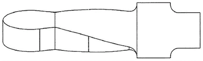
Figure 11 shows a conical marker. The cone may be curved to reduce the triangular effect.
Fig. 12 shows a heart-shaped marker.
Fig. 13 shows a tag having a unique shape formed by a through hole. For example, the marker may appear as a smiley face. Different shapes can be created by varying the size and shape of the through-holes.
Fig. 14 shows a marker shaped like a letter. For example, the tag may be shaped as a capital a. Markers having different letter shapes or having portions shaped like particular letters may help identify a particular marker.
Figure 15 shows a marker shaped like a number. For example, the marker may be in the shape of the number 1. Markers having different number shapes or having portions shaped like a particular number may help to identify a particular marker.
Fig. 16 shows a tag shaped as a rectangle with through slots.
Fig. 17 shows a marker in the shape of a rectangle having a pattern of through holes.
Fig. 18 shows a marker in the shape of a barbed arrow. The protrusions or barbs of the marker may provide a surface that can be imaged from different paths or directions.
Fig. 19 shows a marker contained in a capsule. The capsule may be formed of a bioabsorbable material, such as gelatin, which may be absorbed over time at the biopsy cavity. The capsule may include a marker embedded in the second bioabsorbable material, such as markers 20, 40 described above. During the manufacturing process, the capsule may have uneven characteristics to prevent the two halves from separating. In addition, the two halves of the capsule may be wetted with alcohol or an adhesive to firmly bond the two halves together.
Fig. 20 shows a marker and a pre-curved pusher rod for deploying the marker at a biopsy cavity. The marker may be encapsulated in a bioabsorbable material formed at the end of the pre-bent pushrod. As shown in fig. 21, the marker and pre-curved pusher rod may be deployed through a biopsy needle. The pre-curved push rod may be straightened while in the longitudinal cannula of the biopsy needle. As shown in fig. 22, when the marker reaches the bore of the biopsy needle, the pre-bent push rod may resume its bent shape and the bioabsorbable material holding the marker may protrude from the biopsy needle. The physician operating the biopsy needle will notice that the pre-curved push rod is restored to the curved position. Longitudinal movement of the pre-bent push rod may also be prevented when the push rod returns to the bent configuration. The cutter of the biopsy needle may be used to cut off the tip of the bioabsorbable material including the marker.
Figure 23 shows another marker attached to a pre-bent wire deployer. The pre-bent metal wire may be partially embedded in a bioabsorbable material encapsulating the marker. As shown in fig. 24, the marker and pre-curved wire may be deployed through a biopsy needle. The pre-bent wire may be straightened while in the longitudinal sleeve of the biopsy needle. As shown in fig. 25, when the marker reaches the hole of the biopsy needle, the pre-bent wire may resume its bent shape and the bioabsorbable material holding the marker may protrude from the biopsy needle. The physician operating the biopsy needle will notice that the pre-bent wire returns to the bent configuration. Longitudinal movement of the pre-bent wire may also be prevented when the push rod is restored to the bent configuration. When the pre-bent wire is pulled proximally, the bioabsorbable material can catch on the hole of the biopsy needle or the edge of the cutter, or can otherwise prevent the encapsulated marker from retracting with the wire, thereby removing the wire from the bioabsorbable material and leaving the marker in the biopsy cavity.
Figure 27 shows an elongate marker formed from a bioabsorbable material such as collagen. One or more permanent metallic or ceramic markers may be embedded in the elongated marker. As shown in fig. 28, an elongated marker may be deployed using a marker deployer. The elongated marker may be bent within the marker deployer. As shown in fig. 29, the marker deployer may be deployed through a cannula of a biopsy needle having a lateral aperture. The elongated marker may be pushed to the distal end of the marker deployer with a push rod. As shown in fig. 30, the marker may straighten as the elongated marker is pushed out of the marker deployer. The straightened elongate marker is unlikely to re-enter the bore of the biopsy needle.
Fig. 31 shows spiked spherical markers. The ball may be made of a bioabsorbable material, such as collagen, and may include a permanent marker embedded therein. The tassel may be made of suture material. Spherical markers with ears may be deployed by a marker deployer such that the ears follow the ball. As shown in fig. 32, once the spiked spherical marker is pushed into the biopsy cavity, the spike fans out and helps reduce marker migration.
Fig. 33 illustrates a whisk-shaped marker. The prongs of the marker may remain together during deployment. Once the marker is deployed, the prongs will expand. The prongs may help reduce migration of the marker and may increase the imageable area of the marker.
Fig. 34 shows the shape of the bioabsorbable material surrounding the marker. The bioabsorbable material may be initially formed as a cylinder having one or more X-shaped sections along the length. The bioabsorbable material can be compressed to fit within the marker deployer. The bioabsorbable material may expand within the biopsy cavity. The X-shaped sections may reduce migration and improve imagability. A bioabsorbable material with an X-shaped section can have a larger inscribed volume than a cylinder of bioabsorbable material with the same mass.
Fig. 35 shows the mesh marker within the deployer. A balloon may be used to deploy the mesh marker. As shown in fig. 36, the mesh marker may be deployed through the end of the biopsy needle, and the balloon may be inflated to enlarge the mesh marker. For example, the mesh marker may expand to the size of the biopsy cavity. As shown in fig. 37, the balloon may be deflated and retracted through the biopsy needle, leaving behind the marker.
Figure 38 shows a helical tag. The helical marker may be deployed through the distal end of the biopsy needle. As shown in fig. 39, the helical marker may be deployed by screwing the threaded marker into tissue at the end of the biopsy needle. The marker deployer may be threaded such that the push rod rotates as it travels through the deployer. The helical marker can be firmly fixed within the tissue with little possibility of migration.
Fig. 40 shows a coil marker deployed through a biopsy needle having a lateral aperture. The coiled marker may be a relaxing spring formed of a material that does not permanently elastically deform when elongated. For example, the coil marker may be formed of titanium. The coil marker may be straightened for deployment through a longitudinal cannula of a marker deployer or biopsy needle. When the coil marker is deployed into the biopsy cavity, the coil marker may revert to the coil spring configuration shown in fig. 41.
Fig. 42 shows a plastic marker with bubbles. The plastic marker may be molded around the metal or ceramic marker. When the plastic marker is molded, air bubbles are introduced into the plastic. Glass spheres can also be used as fillers to form bubbles. The bubbles or glass spheres may create density differences in the marker for ultrasound imaging.
Fig. 43 shows a spherical spring marker. The spherical spring marker may be flattened and embedded within the bioabsorbable material. The ball spring marker can be deployed using any of the deployment devices and techniques described herein. The bioabsorbable material can be absorbed at the biopsy cavity and the spherical spring marker can return to a spherical shape.
Figure 44 shows a rugated marker deployer. A corrugated marker deployer may include corrugations, notches, or weak points that predetermine how the marker deployer will deform when longitudinally compressed. For example, a corrugated marker deployer may include a notch to hold a marker and two corrugations proximate to the marker. As shown in fig. 45, when the rugated marker deployer is pushed against the distal end of the biopsy device, the rugated marker deployer may bend at the notch and the rugate such that the marker extends laterally out of the lateral aperture.
Fig. 46A and 46B show a flat marker having two shaped portions and a narrow portion. Each shaped portion has a cut-out on its outer side. In one aspect, the marker can be about 0.1 inch long, 0.037 inch wide and 0.006 inch thick. The size of the marker may vary based on the material of the marker. For example, the size of the titanium marker may be adjusted to be larger than the stainless steel marker.
Fig. 47A and 47B illustrate a twisted tag having two shaped portions and a narrow portion. Each shaped portion has a D-shape and includes a through-hole shaped like the letter D. In one aspect, the marker may be approximately 0.1 inch long, 0.037 inch wide and 0.007 inch thick.
Fig. 48A and 48B show a flat tag having a through hole. In one aspect, the marker may have an elongated oval shape. Each through hole may be shaped like a wide letter D. The marker may be approximately 0.1 inch long, 0.037 inch wide and 0.007 inch thick.
Fig. 49A and 49B show a flat tag having three through holes. The marker may be an elongated oval shape approximately 0.16 inches long, 0.37 inches wide and 0.007 inches thick. The through holes may be of different shapes, for example trapezoidal. The bridge portion may connect the elongate sides between the through holes. The bridging portion may be diagonal or straight.
Fig. 50A and 50B show a twisted marker without a narrow portion. In contrast, a twisted marker may be formed from an elongated oval flat marker. When twisted, the elongate edge of the tag will bend. The marker may be approximately 0.12 inches long, 0.037 inches wide and 0.007 inches thick.
Fig. 51A and 51B show a flat tag having two shaped portions and a narrow portion. The shaped portion may widen toward the outside and narrow toward the middle. The shaped portion may include a similarly shaped through hole. In one aspect, the marker can be approximately 0.1 inch long, 0.026 inch wide and 0.007 inch thick.
Fig. 52A and 52B illustrate a flat tag having two shaped portions and a narrow portion. Each shaped portion may be elongate and include a plurality of through holes. In one aspect, the marker can be approximately 0.13 inches long, 0.026 inches wide and 0.007 inches thick.
Fig. 53A-E show various views of a twisted tag 500 having three shaped portions 502a, 502b, 502c and two narrow portions 504a and 504 b. The contortion marker 500 may be similar to the contortion marker 20 (fig. 2A). Each shaped portion 502 may be shaped as a rounded rectangle. The through-hole 504 may also be shaped as a rounded rectangle. As shown in fig. 53E, the angle between each shaped portion may be about 45 °. That is, the angle between the surface of the shaped portion 502a and the surface of the shaped portion 502b may be a 45 ° angle, and the angle between the surface of the shaped portion 502b and the surface of the shaped portion 502c may be a 45 ° angle. In another aspect, the marker 500 may be twisted such that the angle between each shaped portion 502 may be about 30 °.
Fig. 54A-E show various views of a twisted tag 510 having three shaped portions 512 and two narrow portions 514. The distortion marker 510 may be similar to the distortion marker 20 (fig. 2A). Each shaped portion 512 may be shaped as a rounded rectangle. The through-hole 514 may be circular. As shown in fig. 54E, the angle between the surfaces of each shaped portion may be about 60 degrees. That is, the angle between the surface of the forming portion 512a and the surface of the forming portion 512b may be a 60 degree angle, and the angle between the surface of the forming portion 512b and the surface of the forming portion 512c may be a 60 degree angle. For a marker having three shaped portions, an angle of 60 degrees can cause each flat surface to be twisted at an equal angle to the other surface. That is, the surface of the forming portion 512a may also be at an angle of 60 ° to the surface of the forming portion 512 c. Such an arrangement may present a portion of the surface of the shaped portion from any angle transverse to the axis.
Fig. 55A-E show various views of a twisted tag having two differently shaped portions and an elongated narrow portion. For example, the first shaped portion may be circular. The first forming portion may include a through hole. The second shaped portion may be cross-shaped or plus-shaped. The elongated narrow portion may be twisted. In one aspect, the elongated narrow portion may reduce torsional stress and provide strength against breakage, such as when the bioabsorbable material surrounding the marker is compressed.
Fig. 56A-E show various views of a distorted marker similar to that of fig. 55A-E, except that the distorted marker does not include through-holes.
57A-E illustrate various views of a twisted tag having three shaped portions and two twisted portions. The shaped portion may have different shapes. For example, as shown, the outer shaped portions may be shaped as a cross or plus, and the middle shaped portions may be shaped as a heart. The heart shape may be altered to connect to the stricture. Each shaped portion may also include a through hole (not shown).
Fig. 58A-C show various views of a twisted tag having three shaped portions and two twisted portions. The outer shaping may be similar to that of fig. 57, i.e. shaped like a cross or a plus sign. The central shaped portion may be rectangular. Each stricture portion may be twisted to about 60 degrees.
FIGS. 59A-D show various views of a tag. The marker may have a shaped portion, a twisted portion and a rolled portion. The shaped portion may be any of the shapes discussed herein. For example, as shown in fig. 59A, the shaped portion may be rectangular. The shaped portion may include one or more through holes. The rolled portion may be bent or rolled in one or more dimensions. In one aspect, the rolled portion may be formed from a flat shaped portion that is subsequently rolled or bent. For example, as shown in fig. 59A-D, the rolled portion may be formed from a rectangular flat shaped portion. In one aspect, the marker blank for the marker of FIGS. 59A-D may initially be T-shaped, and then the top of the T may be rolled inward from each side. The rolled portion may also include one or more through holes. As shown, for example, in fig. 59B, the through-holes on each side of the rolled portion may be aligned. The two sides of the rolled portion may be joined, for example, along a central axis of the tag. The twisted portion may connect the forming portion and the rolled portion. In an aspect, one or more sub-portions of the twisted portion may be twisted in different directions. For example, the sub-portions on one side of the twisted portion may be twisted in one direction and the sub-portions on the other side of the twisted portion may be twisted in the opposite direction. In an aspect, the marker may include an undistorted connecting portion, or the forming portion may be formed in contact with the rolled portion.
While the foregoing disclosure discusses illustrative aspects and/or embodiments, it should be noted that various changes and modifications could be made herein without departing from the scope of the described aspects and/or embodiments as defined by the appended claims. Furthermore, although elements of the described aspects and/or embodiments may be described or claimed in the singular, the plural is contemplated unless limitation to the singular is explicitly stated. Additionally, all or a portion of any aspect and/or embodiment may be utilized with all or a portion of any other aspect and/or embodiment, unless stated otherwise.
Claims (13)
1. A biopsy marker comprising:
a first forming section, a second forming section and a third forming section arranged in sequence along an axis, each forming section having a first planar surface;
wherein the first planar surface of the first forming portion is disposed at a first selected angle to the first planar surface of the second forming portion and the first planar surface of the second forming portion is disposed at a second selected angle to the first planar surface of the third forming portion, wherein the first planar surface of the first forming portion is disposed at a third selected angle to the first planar surface of the third forming portion,
wherein the first, second, and third forming portions each define a rectangular shape, each corner of the rectangular shape being rounded.
2. The biopsy marker of claim 1, wherein the second shaped portion has a through hole extending through the first planar surface.
3. The biopsy marker of claim 2, wherein the first and second shaped portions each have a through hole extending through the respective first planar surface.
4. The biopsy marker of claim 2, wherein the first and third shaped portions each have a cut along an outer edge.
5. The biopsy marker of claim 2, wherein each of the three shaped portions has a rectangular shape.
6. The biopsy marker of claim 2, wherein the through hole has a circular cross-section.
7. The biopsy marker of claim 1, wherein the first selected angle and the second selected angle are each approximately 30 degrees.
8. The biopsy marker of claim 1, further comprising a bioabsorbable material surrounding the first, second, and third shaped portions.
9. The biopsy marker of claim 8, wherein the bioabsorbable material is compressed.
10. The biopsy marker of claim 1, further comprising:
a first twisted narrow portion connecting the first forming portion to the second forming portion; and
a second twisted narrow portion connecting the second forming portion to the third forming portion.
11. A method of making a biopsy marker, comprising:
stamping a marker blank from a flat metal sheet, the marker blank comprising:
a first forming section, a second forming section and a third forming section arranged in sequence along an axis, each forming section having a first surface;
twisting the first forming portion about the axis such that the first surface of the first forming portion is disposed at a first selected angle relative to the first surface of the second forming portion,
twisting the third forming portion about the axis such that the first surface of the second forming portion is disposed at a second selected angle relative to the first surface of the third forming portion and such that the first surface of the third forming portion is disposed at a third selected angle relative to the first surface of the first forming portion such that the first surface of the third forming portion is disposed substantially perpendicular relative to the first surface of the first forming portion.
12. The method of claim 11, further comprising:
encapsulating the biopsy marker in a bioabsorbable material; and
compressing the bioabsorbable material around the biopsy marker.
13. The method of claim 11, wherein the marker blank comprises:
a first twisted narrow portion connecting the first forming portion to the second forming portion; and
a second twisted narrow portion connecting the second forming portion to the third forming portion.
Applications Claiming Priority (4)
| Application Number | Priority Date | Filing Date | Title |
|---|---|---|---|
| US201462061586P | 2014-10-08 | 2014-10-08 | |
| US62/061,586 | 2014-10-08 | ||
| CN201580055072.9A CN106794049A (en) | 2014-10-08 | 2015-10-08 | Biopsy marker |
| PCT/US2015/054679 WO2016057785A1 (en) | 2014-10-08 | 2015-10-08 | Biopsy marker |
Related Parent Applications (1)
| Application Number | Title | Priority Date | Filing Date |
|---|---|---|---|
| CN201580055072.9A Division CN106794049A (en) | 2014-10-08 | 2015-10-08 | Biopsy marker |
Publications (1)
| Publication Number | Publication Date |
|---|---|
| CN114376739A true CN114376739A (en) | 2022-04-22 |
Family
ID=54361168
Family Applications (2)
| Application Number | Title | Priority Date | Filing Date |
|---|---|---|---|
| CN201580055072.9A Pending CN106794049A (en) | 2014-10-08 | 2015-10-08 | Biopsy marker |
| CN202210050925.1A Pending CN114376739A (en) | 2014-10-08 | 2015-10-08 | Biopsy markers |
Family Applications Before (1)
| Application Number | Title | Priority Date | Filing Date |
|---|---|---|---|
| CN201580055072.9A Pending CN106794049A (en) | 2014-10-08 | 2015-10-08 | Biopsy marker |
Country Status (6)
| Country | Link |
|---|---|
| US (3) | US10492884B2 (en) |
| EP (1) | EP3203925B1 (en) |
| JP (3) | JP6668339B2 (en) |
| KR (1) | KR20170087866A (en) |
| CN (2) | CN106794049A (en) |
| WO (1) | WO2016057785A1 (en) |
Families Citing this family (5)
| Publication number | Priority date | Publication date | Assignee | Title |
|---|---|---|---|---|
| JP6668339B2 (en) | 2014-10-08 | 2020-03-18 | デヴィコア メディカル プロダクツ, インク.Devicor Medical Products, Inc. | Biopsy marker and method for producing biopsy marker |
| KR102601153B1 (en) * | 2016-05-31 | 2023-11-10 | 코닝 인코포레이티드 | Glass Articles Exhibiting Improved Fracture Performance |
| US11234772B2 (en) | 2017-12-11 | 2022-02-01 | Hologic, Inc. | Ultrasound localization system with advanced biopsy site markers |
| EP4278985A3 (en) | 2019-05-30 | 2024-02-21 | Devicor Medical Products, Inc. | Biopsy site marker for limited migration |
| WO2023249760A1 (en) * | 2022-06-23 | 2023-12-28 | Devicor Medical Products, Inc. | Biopsy site marker with expandable mesh |
Citations (4)
| Publication number | Priority date | Publication date | Assignee | Title |
|---|---|---|---|---|
| CN2212392Y (en) * | 1995-01-20 | 1995-11-15 | 李继明 | Colon transporting test marker with multiple geometric shapes |
| CN101653382A (en) * | 2008-08-22 | 2010-02-24 | 伊西康内外科公司 | Biopsy marker delivery device |
| US20100331668A1 (en) * | 2008-01-31 | 2010-12-30 | Ranpura Himanshu M | Biopsy Tissue Marker |
| CN103140176A (en) * | 2010-08-25 | 2013-06-05 | 德威科医疗产品公司 | Biopsy marker delivery devices and methods |
Family Cites Families (54)
| Publication number | Priority date | Publication date | Assignee | Title |
|---|---|---|---|---|
| US5526822A (en) | 1994-03-24 | 1996-06-18 | Biopsys Medical, Inc. | Method and apparatus for automated biopsy and collection of soft tissue |
| JPH10508504A (en) * | 1994-09-16 | 1998-08-25 | バイオプシス メディカル インコーポレイテッド | Method and apparatus for identifying and marking tissue |
| NO962336L (en) * | 1995-06-06 | 1996-12-09 | Target Therapeutics Inc | Vaso-occlusive spiral |
| US6017316A (en) | 1997-06-18 | 2000-01-25 | Biopsys Medical | Vacuum control system and method for automated biopsy device |
| US6056700A (en) * | 1998-10-13 | 2000-05-02 | Emx, Inc. | Biopsy marker assembly and method of use |
| US6220248B1 (en) * | 1998-10-21 | 2001-04-24 | Ethicon Endo-Surgery, Inc. | Method for implanting a biopsy marker |
| US6371904B1 (en) * | 1998-12-24 | 2002-04-16 | Vivant Medical, Inc. | Subcutaneous cavity marking device and method |
| US20090216118A1 (en) * | 2007-07-26 | 2009-08-27 | Senorx, Inc. | Polysaccharide markers |
| US6086544A (en) | 1999-03-31 | 2000-07-11 | Ethicon Endo-Surgery, Inc. | Control apparatus for an automated surgical biopsy device |
| US6162187A (en) | 1999-08-02 | 2000-12-19 | Ethicon Endo-Surgery, Inc. | Fluid collection apparatus for a surgical device |
| US6432065B1 (en) | 1999-12-17 | 2002-08-13 | Ethicon Endo-Surgery, Inc. | Method for using a surgical biopsy system with remote control for selecting and operational mode |
| US6428487B1 (en) | 1999-12-17 | 2002-08-06 | Ethicon Endo-Surgery, Inc. | Surgical biopsy system with remote control for selecting an operational mode |
| US6350244B1 (en) * | 2000-02-21 | 2002-02-26 | Biopsy Sciences, Llc | Bioabsorable markers for use in biopsy procedures |
| US6602203B2 (en) | 2000-10-13 | 2003-08-05 | Ethicon Endo-Surgery, Inc. | Remote thumbwheel for a surgical biopsy device |
| US6605047B2 (en) * | 2001-09-10 | 2003-08-12 | Vivant Medical, Inc. | Biopsy marker delivery system |
| US6626849B2 (en) | 2001-11-01 | 2003-09-30 | Ethicon Endo-Surgery, Inc. | MRI compatible surgical biopsy device |
| JP4342319B2 (en) * | 2002-03-19 | 2009-10-14 | バード ダブリン アイティーシー リミティッド | Biopsy device and biopsy needle module usable for biopsy device |
| US7744852B2 (en) * | 2003-07-25 | 2010-06-29 | Rubicor Medical, Llc | Methods and systems for marking post biopsy cavity sites |
| US7465279B2 (en) * | 2004-03-31 | 2008-12-16 | Ethicon Endo-Surgery, Inc. | Marker device and method of deploying a cavity marker using a surgical biopsy device |
| US8075568B2 (en) * | 2004-06-11 | 2011-12-13 | Selis James E | Biopsy devices and methods |
| US20060074345A1 (en) | 2004-09-29 | 2006-04-06 | Hibner John A | Biopsy apparatus and method |
| US8280486B2 (en) * | 2004-10-13 | 2012-10-02 | Suros Surgical Systems, Inc. | Site marker visable under multiple modalities |
| US20060247678A1 (en) * | 2005-04-08 | 2006-11-02 | Weisenburgh William B Ii | Surgical instrument system |
| US7854707B2 (en) | 2005-08-05 | 2010-12-21 | Devicor Medical Products, Inc. | Tissue sample revolver drum biopsy device |
| JP5102207B2 (en) * | 2005-08-10 | 2012-12-19 | シー・アール・バード・インコーポレーテッド | Single-insertion, multiple-sampling biopsy device that can be used with various transport systems and integrated markers |
| US7761137B2 (en) * | 2005-12-16 | 2010-07-20 | Suros Surgical Systems, Inc. | Biopsy site marker deployment device |
| US9345457B2 (en) | 2006-12-13 | 2016-05-24 | Devicor Medical Products, Inc. | Presentation of biopsy sample by biopsy device |
| US8702623B2 (en) | 2008-12-18 | 2014-04-22 | Devicor Medical Products, Inc. | Biopsy device with discrete tissue chambers |
| US7938786B2 (en) | 2006-12-13 | 2011-05-10 | Devicor Medical Products, Inc. | Vacuum timing algorithm for biopsy device |
| US20130324882A1 (en) | 2012-05-30 | 2013-12-05 | Devicor Medical Products, Inc. | Control for biopsy device |
| EP2101670B1 (en) | 2006-12-18 | 2013-07-31 | C.R.Bard, Inc. | Biopsy marker with in situ-generated imaging properties |
| EP2180842A1 (en) * | 2007-08-27 | 2010-05-05 | Spine View, Inc. | Balloon cannula system for accessing and visualizing spine and related methods |
| US8454531B2 (en) | 2007-11-20 | 2013-06-04 | Devicor Medical Products, Inc. | Icon-based user interface on biopsy system control module |
| US20090131821A1 (en) | 2007-11-20 | 2009-05-21 | Speeg Trevor W V | Graphical User Interface For Biopsy System Control Module |
| US7854706B2 (en) | 2007-12-27 | 2010-12-21 | Devicor Medical Products, Inc. | Clutch and valving system for tetherless biopsy device |
| US8622924B2 (en) | 2008-02-27 | 2014-01-07 | Devicor Medical Products, Inc. | Needle tip for biopsy device |
| US20100152610A1 (en) | 2008-12-16 | 2010-06-17 | Parihar Shailendra K | Hand Actuated Tetherless Biopsy Device with Pistol Grip |
| US20100160819A1 (en) | 2008-12-18 | 2010-06-24 | Parihar Shailendra K | Biopsy Device with Central Thumbwheel |
| US8083687B2 (en) | 2008-12-18 | 2011-12-27 | Devicor Medical Products, Inc. | Tissue biopsy device with rotatably linked thumbwheel and tissue sample holder |
| KR20110112378A (en) * | 2009-01-06 | 2011-10-12 | 프로테우스 바이오메디컬, 인코포레이티드 | High-throughput production of ingestible event markers |
| US8206316B2 (en) | 2009-06-12 | 2012-06-26 | Devicor Medical Products, Inc. | Tetherless biopsy device with reusable portion |
| EP2756799B1 (en) * | 2009-06-26 | 2016-04-20 | Cianna Medical, Inc. | System for localizing markers or tissue structures within a body |
| US20110028831A1 (en) * | 2009-07-30 | 2011-02-03 | Kent James P | Permanently visible implantable fiduciary tissue marker |
| US20110218433A1 (en) * | 2010-03-02 | 2011-09-08 | Speeg Trevor W V | Biopsy Marker Delivery Device |
| US8764680B2 (en) | 2010-11-01 | 2014-07-01 | Devicor Medical Products, Inc. | Handheld biopsy device with needle firing |
| US8858465B2 (en) | 2011-04-14 | 2014-10-14 | Devicor Medical Products, Inc. | Biopsy device with motorized needle firing |
| US8801742B2 (en) | 2011-06-01 | 2014-08-12 | Devicor Medical Products, Inc. | Needle assembly and blade assembly for biopsy device |
| US8938285B2 (en) | 2011-08-08 | 2015-01-20 | Devicor Medical Products, Inc. | Access chamber and markers for biopsy device |
| US9326755B2 (en) | 2011-08-26 | 2016-05-03 | Devicor Medical Products, Inc. | Biopsy device tissue sample holder with bulk chamber and pathology chamber |
| US8798716B1 (en) * | 2011-11-03 | 2014-08-05 | Solstice Corporation | Fiducial markers and related methods |
| JP2014030555A (en) * | 2012-08-02 | 2014-02-20 | Terumo Corp | Medical instrument |
| CN103961802A (en) * | 2013-01-28 | 2014-08-06 | 刘苗生 | Self-deforming metal marker |
| KR101863804B1 (en) * | 2013-07-19 | 2018-06-04 | 데비코어 메디컬 프로덕츠, 인코포레이티드 | Biopsy device targeting features |
| JP6668339B2 (en) | 2014-10-08 | 2020-03-18 | デヴィコア メディカル プロダクツ, インク.Devicor Medical Products, Inc. | Biopsy marker and method for producing biopsy marker |
-
2015
- 2015-10-08 JP JP2017519308A patent/JP6668339B2/en active Active
- 2015-10-08 CN CN201580055072.9A patent/CN106794049A/en active Pending
- 2015-10-08 EP EP15787352.2A patent/EP3203925B1/en active Active
- 2015-10-08 WO PCT/US2015/054679 patent/WO2016057785A1/en active Application Filing
- 2015-10-08 CN CN202210050925.1A patent/CN114376739A/en active Pending
- 2015-10-08 KR KR1020177011801A patent/KR20170087866A/en unknown
-
2017
- 2017-04-04 US US15/478,929 patent/US10492884B2/en active Active
-
2019
- 2019-10-30 US US16/668,610 patent/US11123151B2/en active Active
-
2020
- 2020-02-26 JP JP2020030882A patent/JP7053698B2/en active Active
-
2021
- 2021-08-24 US US17/409,879 patent/US20220008160A1/en active Pending
-
2022
- 2022-03-31 JP JP2022058961A patent/JP7465904B2/en active Active
Patent Citations (4)
| Publication number | Priority date | Publication date | Assignee | Title |
|---|---|---|---|---|
| CN2212392Y (en) * | 1995-01-20 | 1995-11-15 | 李继明 | Colon transporting test marker with multiple geometric shapes |
| US20100331668A1 (en) * | 2008-01-31 | 2010-12-30 | Ranpura Himanshu M | Biopsy Tissue Marker |
| CN101653382A (en) * | 2008-08-22 | 2010-02-24 | 伊西康内外科公司 | Biopsy marker delivery device |
| CN103140176A (en) * | 2010-08-25 | 2013-06-05 | 德威科医疗产品公司 | Biopsy marker delivery devices and methods |
Also Published As
| Publication number | Publication date |
|---|---|
| EP3203925B1 (en) | 2024-03-13 |
| JP7053698B2 (en) | 2022-04-12 |
| US20200060787A1 (en) | 2020-02-27 |
| JP2017534370A (en) | 2017-11-24 |
| US20170202635A1 (en) | 2017-07-20 |
| WO2016057785A1 (en) | 2016-04-14 |
| US20220008160A1 (en) | 2022-01-13 |
| JP2020078628A (en) | 2020-05-28 |
| CN106794049A (en) | 2017-05-31 |
| US10492884B2 (en) | 2019-12-03 |
| KR20170087866A (en) | 2017-07-31 |
| US11123151B2 (en) | 2021-09-21 |
| JP2022084923A (en) | 2022-06-07 |
| JP7465904B2 (en) | 2024-04-11 |
| JP6668339B2 (en) | 2020-03-18 |
| EP3203925A1 (en) | 2017-08-16 |
Similar Documents
| Publication | Publication Date | Title |
|---|---|---|
| US11123151B2 (en) | Biopsy marker | |
| US11779432B2 (en) | Marking device and implantation system | |
| AU2020202038B2 (en) | Implantable devices and techniques for oncoplastic surgery | |
| EP3344160B1 (en) | Elastic orthopedic implant and method of manufacture thereof | |
| EP2204148B1 (en) | Implant for treatment of obstructive sleep apnea | |
| EP1778077B1 (en) | Wireless markers for anchoring within a human body | |
| ES2534192T3 (en) | Features of mesh ball embolic device | |
| EP2805681B1 (en) | Improved embolic coil | |
| US20080065154A1 (en) | Surgical staple | |
| CN101461981A (en) | Oriented dilatation balloon and oriented dilatation device | |
| US20200054413A1 (en) | Marking Body, Method for the Production and Use of a Marking Body | |
| KR102090211B1 (en) | Suture Manufacturing Method | |
| US20190183600A1 (en) | Device for anchoring and identifying multiple suspected lesions anchoring devices | |
| US20220241048A1 (en) | Implantable Marker | |
| DE112021003841T5 (en) | IMPLANTABLE MARKER AND PARTS SET | |
| CN104939948A (en) | Ossicular prosthesis having a longitudinally perforated bight | |
| CN217645337U (en) | Stereotactic radiotherapy tracking marker | |
| DE102021116873A1 (en) | Implantable marker | |
| WO2024039560A1 (en) | Biopsy site marker having expandable portion | |
| CN116096462A (en) | Reference positioning mark for radiotherapy |
Legal Events
| Date | Code | Title | Description |
|---|---|---|---|
| PB01 | Publication | ||
| PB01 | Publication | ||
| SE01 | Entry into force of request for substantive examination | ||
| SE01 | Entry into force of request for substantive examination |