JP6660496B2 - Measuring device, measuring method and program - Google Patents
Measuring device, measuring method and program Download PDFInfo
- Publication number
- JP6660496B2 JP6660496B2 JP2019021501A JP2019021501A JP6660496B2 JP 6660496 B2 JP6660496 B2 JP 6660496B2 JP 2019021501 A JP2019021501 A JP 2019021501A JP 2019021501 A JP2019021501 A JP 2019021501A JP 6660496 B2 JP6660496 B2 JP 6660496B2
- Authority
- JP
- Japan
- Prior art keywords
- measurement
- illuminometer
- measuring device
- dimensional
- unit
- Prior art date
- Legal status (The legal status is an assumption and is not a legal conclusion. Google has not performed a legal analysis and makes no representation as to the accuracy of the status listed.)
- Active
Links
- 238000000034 method Methods 0.000 title claims description 52
- 238000005259 measurement Methods 0.000 claims description 192
- 230000008569 process Effects 0.000 claims description 21
- 238000004364 calculation method Methods 0.000 claims description 15
- 238000005286 illumination Methods 0.000 claims description 4
- 238000012545 processing Methods 0.000 description 19
- 238000004891 communication Methods 0.000 description 15
- 230000006870 function Effects 0.000 description 10
- 238000010586 diagram Methods 0.000 description 6
- 238000002271 resection Methods 0.000 description 6
- 230000033001 locomotion Effects 0.000 description 5
- 230000008602 contraction Effects 0.000 description 4
- 238000009434 installation Methods 0.000 description 3
- 230000001678 irradiating effect Effects 0.000 description 3
- 238000013461 design Methods 0.000 description 2
- 230000007246 mechanism Effects 0.000 description 2
- 238000013459 approach Methods 0.000 description 1
- 230000005540 biological transmission Effects 0.000 description 1
- 230000004397 blinking Effects 0.000 description 1
- 230000008859 change Effects 0.000 description 1
- 239000004973 liquid crystal related substance Substances 0.000 description 1
- 230000003287 optical effect Effects 0.000 description 1
- 230000005855 radiation Effects 0.000 description 1
- 239000004065 semiconductor Substances 0.000 description 1
- 238000011426 transformation method Methods 0.000 description 1
Images


Description
本発明は、照度の測定を行なう技術に関する。 The present invention relates to a technique for measuring illuminance .
例えば、車両のヘッドライトの性能を調べる技術が知られている(例えば、特許文献1参照)。 For example, a technique for examining the performance of a headlight of a vehicle is known (for example, see Patent Document 1).
車両のヘッドライドの性能を調べる方法として、車両の前方に複数の測定予定位置を設定し、各測定予定位置における照度を測定する方法がある。この場合、各測定予定位置を特定する作業が必要となる。測定予定位置は、三次元空間中に設定されているので、その位置を特定する作業は煩雑である。 As a method of examining the performance of a head ride of a vehicle, there is a method of setting a plurality of planned measurement positions in front of the vehicle and measuring the illuminance at each measurement planned position. In this case, it is necessary to perform an operation for specifying each measurement scheduled position. Since the scheduled measurement position is set in the three-dimensional space, the operation of specifying the position is complicated.
このような背景において、本発明は、簡便な方法で三次元空間における照度の測定位置を決めることができる技術を提供することを目的とする。 In such a background, an object of the present invention is to provide a technique capable of determining a measurement position of illuminance in a three-dimensional space by a simple method.
請求項1に記載の発明は、照度計による照度の測定を行う候補となる測定予定位置の三次元位置と位置測定装置によって測定された前記照度計の三次元位置との関係を表示装置に表示するための制御を行う制御部を備えることを特徴とする測定装置である。
The invention according to
請求項2に記載の発明は、請求項1に記載の発明において、前記制御部は、前記測定予定位置への方向と距離を表示する制御を行うことを特徴とする。 According to a second aspect of the present invention, in the first aspect of the present invention, the control unit performs control for displaying a direction and a distance to the planned measurement position.
請求項3に記載の発明は、請求項1または請求項2に記載の発明において、前記測定予定位置と前記測定された前記照度計の三次元位置との間の距離が予め定めた値以下となった段階で報知表示を行う制御を行う報知制御部を備えることを特徴とする。 According to a third aspect of the present invention, in the first or second aspect, a distance between the measured position and the measured three-dimensional position of the illuminometer is equal to or less than a predetermined value. It is characterized by including a notification control unit that performs control for performing notification display at the time when the notification is made.
請求項4に記載の発明は、請求項1〜3のいずれか一項に記載の発明において、前記照度計が測定する照明光の発生源を備えた対象物の点群位置データを取得する点群位置データ取得部と、前記測定予定位置と前記対象物との位置関係および前記点群位置データに基づいて作成された前記対象物の三次元モデルに基づき、前記対象物に対する前記位置測定装置の位置を算出する位置算出部とを備えることを特徴とする。 According to a fourth aspect of the present invention, in the invention according to any one of the first to third aspects, a point for acquiring point cloud position data of an object including a source of illumination light measured by the illuminometer is provided. A group position data acquisition unit, based on a three-dimensional model of the target object created based on the positional relationship between the planned measurement position and the target object and the point cloud position data, based on the position measurement device for the target object; A position calculation unit for calculating a position.
請求項5に記載の発明は、請求項4に記載の発明において、前記位置測定装置は、レーザスキャナの機能を有し、前記点群位置データは、前記レーザスキャナの機能によって得られることを特徴とする。 According to a fifth aspect of the present invention, in the fourth aspect, the position measuring device has a function of a laser scanner, and the point cloud position data is obtained by a function of the laser scanner. And
請求項6に記載の発明は、請求項4または5に記載の発明において、前記位置算出部は、前記対象物と前記三次元モデルの対応関係に基づき、前記対象物に対する前記位置測定装置の位置を算出することを特徴とする。 According to a sixth aspect of the present invention, in the fourth or fifth aspect of the present invention, the position calculating unit is configured to determine a position of the position measuring device with respect to the object based on a correspondence between the object and the three-dimensional model. Is calculated.
請求項7に記載の発明は、請求項6に記載の発明において、前記位置算出部は、前記対象物と前記三次元モデルの対応関係から前記三次元モデルを構成する複数の点の位置を求める処理と、該処理で求めた前記複数の点の座標に基づく後方交会法により前記位置測定装置の位置を求める処理とを行うことを特徴とする。 According to a seventh aspect of the present invention, in the invention according to the sixth aspect, the position calculating unit obtains positions of a plurality of points constituting the three-dimensional model from a correspondence between the object and the three-dimensional model. And performing a process of obtaining the position of the position measuring device by a rear intersection method based on the coordinates of the plurality of points obtained in the process.
請求項8に記載の発明は、照度計による照度の測定を行う候補となる測定予定位置の三次元位置と位置測定装置によって測定された前記照度計の三次元位置との関係を表示装置に表示するための制御を行う制御ステップを備えることを特徴とする測定方法である。 The invention according to claim 8 displays, on a display device, the relationship between the three-dimensional position of a measurement planned position which is a candidate for measuring illuminance by the illuminometer and the three-dimensional position of the illuminometer measured by the position measuring device. And a control step for performing control for performing the measurement.
請求項9に記載の発明は、コンピュータに読み取らせて実行させるプログラムであって、コンピュータに照度計による照度の測定を行う候補となる測定予定位置の三次元位置と位置測定装置によって測定された前記照度計の三次元位置との関係を表示装置に表示するための制御を行う制御ステップを実行させることを特徴とするプログラムである。 The invention according to claim 9 is a program for causing a computer to read and execute the program, wherein the computer measures a three-dimensional position of a planned measurement position that is a candidate for measuring illuminance by an illuminometer and the program is measured by a position measuring device. A program for executing a control step for performing control for displaying a relationship between a three-dimensional position of an illuminometer and a three-dimensional position on a display device.
本発明によれば、簡便な方法で三次元空間における照度計の測定位置を決めることができる。 According to the present invention, the measurement position of the illuminometer in the three-dimensional space can be determined by a simple method.
1.第1の実施形態
(概要)
図1には、実施形態における照度の測定を行なう作業の概要が示されている。この例では、作業者100が、測定ユニット200を用いて予め定められた測定点における照度を測定する。図1には、作業者100が測定ユニット200および端末300を持って移動し、3カ所において測定を行なう場合の例が概念的に示されている。
1. First Embodiment (Overview)
FIG. 1 shows an outline of an operation for measuring illuminance in the embodiment. In this example, the
(ハードウェアの構成)
(測定ユニット)
測定ユニット200は、棒状の支持ポール201、支持ポール201の先端に固定された反射プリズム202、反射プリズム202の上に固定された照度計203を備えている。支持ポール201は、伸縮が可能であり、反射プリズム202および照度計203の高さの位置を作業者が希望する位置に調整できる構造を有している。支持ポール210を伸縮させる機構は、作業者が手動で行う構造が採用されている。この伸縮を行う機構として、各種のアクチュエータや電動モータを用いることもできる。
(Hardware configuration)
(Measurement unit)
The
反射プリズム202は、位置測定装置400からの測定用レーザ光を位置測定装置400に向けて反射する。照度計203は、電磁波測定器の一例であり、照明光の照度を測定する。照度計203は、作業者が手にする端末300に接続されており、端末300の操作により動作する。照度計203が測定した照度のデータは、端末300に記憶される。照度計203は、水平面内の特定の方向に対して指向性を有している。支持ポール201を軸回りで回転させることで、照度計203の測定方向を調整できる。なお、端末300を支持ポール201に取り付け、端末300が測定ユニット200と共に移動する構成も可能である。
The reflecting
(位置測定装置)
位置測定装置400は、測定用レーザ光を周囲に向かって走査しつつ照射する。この測定用レーザ光が反射プリズム202に当たるとそこで反射され、その反射光が位置測定装置400で受光される。位置測定装置400は、測定用レーザ光の照射方向と伝搬時間とから位置測定装置400からの反射プリズム202の方向と距離を算出する。この結果、位置測定装置400に対する反射プリズム202の相対的な位置関係が判明する。ここで、位置測定装置400の位置を予め定めておくことで、反射プリズム202の位置の情報が得られる。この例では、後述する車両のヘッドライトおよびテールライトの測定を行う想定フィールド(測定が行われる場所)における位置測定装置400の位置を予め決めておく。例えば、上述した測定フィールドには当該測定フィールド内での位置が明確な基準点が一または複数設けられており、この基準点に位置測定装置400を設置することで、当該測定フィールドにおける位置測定装置400の位置を予め既知点とすることができる。なお、位置測定装置400の位置を予め高精度GNSS装置等を用いて測定する方法も可能である。
(Position measuring device)
The position measuring
図2に位置測定装置400のブロック図を示す。位置測定装置400は、測定光照射部401、反射光受光部402、スキャン制御部403、ターゲット方位取得部404、距離算出部405、ターゲット位置算出部406および通信部407を備えている。測定光照射部401は、距離測定用のレーザ光を周囲に向けて走査しつつ照射する。反射光受光部402は、ターゲット(図1の反射プリズム202)に当たり、そこで反射された測定光を受光する。測定光照射部401と反射光受光部402とは、回転が可能な架台に乗せられており、周囲をスキャンしつつ測定光の照射と反射光の受光が可能とされている。
FIG. 2 shows a block diagram of the
スキャン制御部403は、上記の測定光のスキャンを制御する。例えば、スキャンのタイミング、スキャンの方向、測定用レーザ光の発光のタイミングの制御がスキャン制御部403によって行われる。ターゲット方位取得部404は、測定光の照射方向(反射光の入射方向)から、位置測定装置400から見たターゲット(この場合は、反射プリズム202)の方向を取得する。この例では、ターゲット方位取得部404は、水平角と上下角(仰角または俯角)の角度データを取得する。距離算出部405は、測定光の飛翔時間(伝搬時間)と光速から位置測定装置400からターゲットまでの距離を算出する。
The
ターゲット位置算出部406は、位置測定装置400から見たターゲットの方向、および位置測定装置400とターゲットの間の距離に基づき、位置測定装置400に対するターゲットの位置を算出する。ここで、予め位置測定装置400の測定フィールドにおける位置が判っていれば、ターゲット(図1の反射プリズム202)の測定フィールドにおける位置を知ることができる。
The target
例えば、測定フィールドにおける位置測定装置400の位置P0(x’y’z’)が既知であり、このデータが位置測定装置400に入力されている場合を考える。この場合、位置測定装置400の位置を原点とした三次元座標系における測定された反射プリズム202の位置をP1(xyz)とすると、測定フィールドにおける反射プリズム202の位置(座標)Pは、P=P0+P1により求まる。この処理もターゲット位置算出部406で行われる。なお、P0の値を端末300に入力させておき、上記のPを求める演算を端末300で行うことも可能である。
For example, consider a case where the position P 0 (x′y′z ′) of the
なお、位置測定装置400の絶対位置が既知である場合、ターゲットの絶対位置を算出できる。またこの例では、反射プリズム202と照度計203とは近接して配置されており、反射プリズム202の位置を照度計203の位置とみなしている。
When the absolute position of the
通信部407は、端末300との間で無線通信を行う。無線通信の規格は特に限定されないが、例えばWi−Fi、Bluetooth(登録商標)、各種の無線LAN、携帯電話網等の通信規格が利用される。通信部407は、ターゲット位置算出部406が算出したターゲット(図1の反射プリズム202)の位置に関するデータを端末300に送信する。また、予め求めておいた(あるいは予め定まっている)位置測定装置400の位置のデータが通信部407を介して位置測定装置400に入力される。
The
(端末)
図1に戻り、作業者100は、端末300を携帯している。端末は、携帯型の汎用コンピュータとして利用可能な市販のタブレットであり、CPU、メモリおよび各種のインターフェースを備えている。端末300としては、汎用のコンピュータを利用する以外に専用の端末を用意し、それを用いてもよい。作業者100は、端末300を用いて照度の測定に係る作業を行う。
(Terminal)
Returning to FIG. 1, the
端末300は、通信部301、測定予定位置データ受付部302、測定位置データ受付部303、位置判定部304、測定指示報知部305、GUI制御部306および表示部307を備えている。この例では、通信部301および表示部307は、タブレットが備えたハードウェアが利用され、それ以外の機能部は、ソフトウェア的に構成されており、CPUにより特定のプログラムが実行されることでその動作が実現される。
The terminal 300 includes a
図示する各機能部の少なくとも一部を専用の回路によって構成してもよい。例えば、図示する各機能部は、CPU(Central Processing Unit)、ASIC(Application Specific Integrated Circuit)、FPGA(Field Programmable Gate Array)などのPLD(Programmable Logic Device)などの電子回路により構成することができる。 At least a part of each of the illustrated functional units may be configured by a dedicated circuit. For example, each of the illustrated functional units can be configured by an electronic circuit such as a PLD (Programmable Logic Device) such as a CPU (Central Processing Unit), an ASIC (Application Specific Integrated Circuit), and an FPGA (Field Programmable Gate Array).
各機能部を専用のハードウェアで構成するのか、CPUにおけるプログラムの実行によりソフトウェア的に構成するのかは、要求される演算速度、コスト、消費電力等を勘案して決定される。例えば、特定の機能部をFPGAで構成すれば、処理速度の上では優位であるが高コストとなる。他方で、CPUでプログラムを実行することで特定の機能部を実現する構成は、汎用のハードウェアを利用できるのでコスト的に優位となる。しかしながら、CPUで機能部を実現する場合、処理速度は、専用のハードウェアに比較して見劣りする。また、CPUで機能部を実現する場合、複雑な演算に対応できない場合もあり得る。なお、機能部を専用のハードウェアで構成することとソフトウェア的に構成することとは、上述した違いはあるが、特定の機能を実現するという観点からは、等価である。また、一つの回路で複数の機能部を実現する構成も可能である。 Whether each functional unit is configured as dedicated hardware or configured as software by executing a program in the CPU is determined in consideration of required calculation speed, cost, power consumption, and the like. For example, if a specific functional unit is configured by an FPGA, the processing speed is superior but the cost is high. On the other hand, a configuration in which a specific functional unit is realized by executing a program by the CPU is advantageous in cost because general-purpose hardware can be used. However, when the functional unit is implemented by the CPU, the processing speed is inferior to that of dedicated hardware. Further, when the functional unit is realized by the CPU, it may not be possible to cope with a complicated calculation. The configuration of the functional unit by dedicated hardware and the configuration by software are different from each other, but are equivalent from the viewpoint of realizing a specific function. Further, a configuration in which a plurality of functional units are realized by one circuit is also possible.
通信部301は、位置測定装置400(図1および図2参照)および他の装置との間で通信を行う。通信の規格は、公知の各種のものを利用できる。測定予定位置データ受付部302は、照度の測定を行う候補となる予定位置である測定予定位置に係るデータを受け付ける。照度の測定を行う測定予定位置は、予め決められており、通信部301を介して端末300に入力される。勿論、公知の記憶媒体(USBメモリ等)を介して、測定予定位置のデータを端末300に入力してもよい。なお、受け付けた測定予定位置のデータは、端末300の図示しない記憶手段(半導体メモリ等)に記憶される。
The
測定位置データ受付部303は、位置測定装置400が測定した反射プリズム202の測定位置のデータを受け付ける。この測定位置のデータは、通信部301で受信され、測定位置データ受付部303に送られる。
The measurement position data reception unit 303 receives data of the measurement position of the
位置判定部304は、測定位置データ受付部303が受け付けた反射プリズム202の測定位置と、測定予定位置データ受付部302が受け付けた予め決められている測定予定位置とを比較し、測定位置と測定予定位置の差が予め定めた範囲以下であるか否かを判定する。測定指示報知部305は、位置判定部304が測定位置と測定予定位置の差が予め定めた範囲以下であると判定した場合に、照度の測定を作業者に促す報知に係る処理を行う。
The
GUI制御部306は、後述するGUI(Graphical User Interface)の制御を行う。GUIの制御は、通常のタブレットが備える機能を利用して行われる。GUI制御部により、後述するUI(User Interface)表示の制御が行なわれる。表示部307は、端末300が備える液晶表示装置である。表示部307は、タッチパネルセンサを備え、画面を用いた各種の操作が行なえる仕様となっている。この点は、市販されているタブレットの機能を利用している。
The
また、端末300は、姿勢センサを備えており(外付けでもよい)、後述するキャリブレーションを行うことで、測定環境における端末300の姿勢を取得する機能を有している。 Further, the terminal 300 is provided with a posture sensor (may be externally attached), and has a function of acquiring the posture of the terminal 300 in the measurement environment by performing calibration described later.
(動作の概要)
位置測定装置400は、ターゲットである図1の反射プリズム202の位置を測定し、その情報を端末300に無線通信で送信する。端末300は、予め定めた測定予定位置と位置測定装置400が測定した反射プリズム202の測定位置とを比較し、その位置関係を算出する。また、反射プリズム202の測定予定位置と実際に測定した測定位置との位置関係が端末300の表示部307にグラフィカルに表示される(図4参照)。
(Outline of operation)
The
作業者は、この端末300の表示部307に表示された図4に例示されるUI画面を見て、測定ユニット200と共に測定予定位置に近づく。そして、特定の条件が満足された場合に、照度の測定を促す報知が作業者に行われる。この報知を受け、作業者は、その位置で照度計203(図1参照)を用いた照度の測定を行う。この作業を測定予定位置毎に繰り返すことで、各測定予定位置における照度の測定が行われる。
The operator looks at the UI screen illustrated in FIG. 4 displayed on the
(GUI表示画面の一例)
図4に端末300(図3参照)の表示部307に表示されるGUI画面(UI画面)の一例を示す。図4に示す画面を用いたGUIの制御は、GUI制御部306において行われる。図4(A)には、その時点における反射プリズム202の位置を基準とした測定予定位置の方向(方位)、測定予定位置までの水平方向の距離、および垂直方向の距離が表示されている。図4の場合、その時点における反射プリズム202に位置から、右斜め前方45°の方向に水平距離で12m、垂直方向に+1.2mの位置に測定予定位置がある状態が示されている。なお、詳細は後述するが、端末300は、姿勢センサを有し、図4の表示画面の向きを周囲環境に合った向きとなるように表示が制御されている。すなわち、端末300の向きによらず、表示される矢印が常に測定予定位置の方向を向くように矢印の表示が制御されている。
(Example of GUI display screen)
FIG. 4 shows an example of a GUI screen (UI screen) displayed on the
図4(B)には、測定予定位置まで、X方向(右方向)に1.45m、Y方向(前方向)に1.38m、高さ方向で後1.2mの位置まで反射プリズム202が近付いた状態が示されている。この場合、反射プリズム202をX方向(右方向)に1.45m、Y方向(前方向)に1.38m動かし、更に鉛直上の方向に1.2m動かすことで、反射プリズム202の位置が測定予定位置となる。なお、反射プリズム202と照度計203の位置は近接しており、両者は同一の三次元位置にあるとみなせるので、反射プリズム202を測定予定位置に動かすことで、測定予定位置での照度計203による照度の測定が可能となる。
FIG. 4 (B) shows that the
図4(C)には、測定予定位置に対して、X方向(右方向)に0.58m、Y方向(前方向)に0.56mの位置まで近づいた状態が示されている。図4(C)には、水平面内では反射プリズム202の位置が70cm以下の距離に近づいたが、鉛直方向の距離が測定予定位置まで1.2m不足している状態が示されている。
FIG. 4C shows a state in which the position is approaching a position of 0.58 m in the X direction (right direction) and 0.56 m in the Y direction (forward direction) with respect to the planned measurement position. FIG. 4C shows a state in which the position of the reflecting
この例では、測定予定位置から半径70cm以内で照度の測定を行う仕様とされており、反射プリズム202の測定位置と測定予定位置との水平距離が70cmに近くなると、その旨が画面上で確認できるように画面上に半径70cmに相当する同心円が表示される。
In this example, the illuminance is measured within a radius of 70 cm from the planned measurement position. When the horizontal distance between the measurement position of the
図4(D)には、高さ方向で−0.17mの位置まで反射プリズム202が近付いた状態が示されている。ここで、−0.17mという表示は、測定予定位置が反射プリズム202よりも0.17m低い位置にあることを示している。この場合、反射プリズム202の高さ位置を0.17m下げると、反射プリズム202は測定予定位置の高さとなる。図4(D)には、水平方向の距離に加えて鉛直方向の距離も70cm以内の範囲となった状態が示されている。この例では、反射プリズム202の測定予定位置と測定位置との距離が70cm以下になると、画面の一部の色や濃淡の変化、点滅といった強調表示となり、その旨が作業者に報知される。この報知は、音響的なものを利用することもできる。図4(D)の例では、「測定」を指示するアイコンが強調表示された状態が示されている。この場合、作業者が画面上の強調表示された部分に触れると、照度の測定が照度計203によって行われる。
FIG. 4D shows a state in which the reflecting
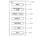
(処理の一例)
図5には、処理の手順の一例を示すフローチャートが示されている。図5の処理を実行するためのプログラムは、端末300内のメモリに記憶されている。このプログラムは、適当な記憶媒体に記憶させ、そこから提供される形態であってもよい。これは、図5や図9の処理についても同じである。
(Example of processing)
FIG. 5 is a flowchart illustrating an example of the processing procedure. A program for executing the processing in FIG. 5 is stored in a memory in
ここでは、車両600のライト(ヘッドライトとテールランプ)の照度を測定する例を説明する。図6には、車両600の前方と後方の三次元空間中に格子状に複数の測定予定位置601が設定された状態が示されている。なお、ここでは車両として乗用車の例を示すが、トラックやバス、クレーン車等の特殊車両であってもよい。
Here, an example in which the illuminance of the lights (headlights and tail lamps) of the
図6に示す測定予定位置601の車両600に対する相対位置関係、および測定予定位置の格子間隔は予め定められている。例えば、当該車両の設計時に測定予定位置が決められ、また各測定予定位置における照度の測定値の下限や範囲も予め定められている。ここでは、照度の例を説明するが、照明光の色度についての基準を定め、例えば各測定点における色度の範囲を予め定めることもできる。なお、図6の測定を行う測定フィールドは、野外でもよいし、室内であってもよい。
The relative positional relationship of the planned
測定に先立ち、まず位置測定装置400を既知の位置に設置する。次に、端末300のキャリブレーションを行い端末300が方位を測定できるようにする。この処理は、以下のようにして行われる。まず、端末300に図6の測定が行われる測定フェールドの地図情報を入力する。そして、当該測定フィールドの複数の位置で端末300の位置を、位置測定装置400を用いて測定する。この処理では、反射プリズム202に端末300を近接させ、端末300の位置を測定する。各測定点における端末300の姿勢は、端末300が内蔵する姿勢センサによって判るので、上記の当該測定フィールドの地図情報と端末300の姿勢との関係を取得する。この結果、図4の情報を端末300の表示部307に表示させた際に、現場の状況にあった画面の向きが常に表示できるようになる。すなわち、端末300の向きを変えても常に測定予定位置の方向が視覚的に把握できるように図4の表示が行われる。
Prior to the measurement, first, the
以下、図5を参照して作業の手順の一例を説明する。まず、位置測定装置400の位置データを端末300に入力する(ステップS101)。上述したように、位置測定装置400の測定フィールド上における設置位置は既知であり、その位置データが端末300に入力される。次に、予め定めておいた図6に例示する測定予定位置のデータを端末400に入力する(ステップS102)。
Hereinafter, an example of an operation procedure will be described with reference to FIG. First, the position data of the
ステップS101およびS102の処理が終了したら、端末300を利用した作業者100の測定点への誘導に係る処理が行なわれる(ステップS103)。ステップ103では、以下の処理が行なわれる。まず、端末上で図4に例示する処理に係るプログラムを起動すると、最初に到達すべき測定予定位置601(図6の格子点の一つ)が選択され、そこへの誘導を促すUI画面表示(図4参照)が端末300の表示部307に表示される。作業者100は、図4に例示されるUI表示を利用して、格子状に設定された測定予定位置601の一つに照度計203を誘導する。この作業は、作業者が端末300を見ながら測定ユニット200を手に持ち、徒歩で移動することで行われる。
When the processes of steps S101 and S102 are completed, a process related to the guidance of the
例えば、最初に図4(A)の表示が行われた場合、作業者は、表示された測定予定位置の方位と距離を把握し、当該測定予定位置に向かって徒歩で移動する。測定予定位置に近づくと、図4(B)に示すような、現在位置と測定予定位置との相対位置関係が視覚的に把握し易い表示画面に切り替わる。図4(B)の状態から更に測定予定位置に近づき、水平面内における反射プリズム202の位置が測定予定位置と見なせる範囲(この場合は、半径70cmの範囲)に入った状態が図4(C)に示されている。
For example, when the display of FIG. 4A is first performed, the worker grasps the azimuth and the distance of the displayed planned measurement position and moves on foot toward the measured measurement position. When approaching the scheduled measurement position, the display screen is switched to a display screen as shown in FIG. 4B in which the relative positional relationship between the current position and the scheduled measurement position can be easily grasped visually. FIG. 4C shows a state in which the position of the reflecting
図4(C)の状態から更に目標とする水平面内の位置に近づき、更に支持ポール201の長さを調整して反射プリズム202の高さ位置を調整した状態が図4(D)に示されている。図4(D)には、反射プリズム202の三次元位置が測定予定位置から半径70cmの範囲内に入り、その旨を作業者100に報知する強調表示が行われている状態が示されている。この例では、測定の開始を指示する画面上のアイコンが点滅し、反射プリズム202(照度計203)が測定予定位置に到達し、照度の測定が可能な状態である旨を作業者100に報知する画面表示が行われる。
FIG. 4D shows a state in which the position in the horizontal plane is further approached from the state shown in FIG. 4C, and the height position of the reflecting
この段階で作業者が端末300を操作し、照度の測定を指示すると、照度計203による照度の測定が行われる(ステップS104)。測定された照度のデータは、端末300内のメモリに設定された記憶ファイルに記憶される。この際、測定位置の座標データおよび測定時刻のデータと関連付けして照度のデータが記憶される(ステップS105)。なお、照度の測定においては、鉛直方向の測定と水平方向の測定を行う。鉛直方向の測定の場合は、照度計が車両を向くように照度計の向きを調整して測定し、水平方向の測定の場合は、照度計を天頂方向に調整して行う。
At this stage, when the operator operates the terminal 300 and instructs to measure the illuminance, the
以上の処理を格子状に設定された各測定予定位置601において順次行うことで、各測定予定位置における照度のデータが得られる。
By sequentially performing the above-described processing at each of the measurement planned
図7にステップS103に係る処理の一例を示す。この処理は、端末300の位置判定部304において行われる。この処理では、まず測定予定位置P1の位置データを取得する(ステップS201)。次に、実際に測定した反射プリズム202の位置データP2を取得する(ステップS202)。次に、P1とP2の位置の差(P1とP2の距離)ΔPを算出する(ステップS203)。
FIG. 7 shows an example of the process according to step S103. This processing is performed by the
ΔPを算出したら、ΔPが予め定めた規定値(例えば70cm)以下であるか否か、を判定する(ステップS204)。ΔPが規定値以下であれば、報知処理を行い(ステップS205)、ΔPが規定値以下でなければ、ステップS202以下の処理を繰り返す。 After calculating ΔP, it is determined whether ΔP is equal to or smaller than a predetermined value (for example, 70 cm) (step S204). If ΔP is equal to or smaller than the specified value, a notification process is performed (step S205), and if ΔP is not equal to or smaller than the specified value, the processes in and after step S202 are repeated.
(優位性)
上記の例によれば、端末の表示部に測定すべき位置への誘導を促す表示が行われるので、照度計203の位置の特定に係る作業を効率化できる。
(Superiority)
According to the above example, a display prompting guidance to the position to be measured is displayed on the display unit of the terminal, so that the work related to specifying the position of the
2.第2の実施形態
(初めに)
本実施形態は、第1の実施形態において、位置測定装置400の位置のデータを取得する技術に関する。第1の実施形態では、最初に測定フィールドにおける位置測定装置400の位置を決め、その位置データを取得する必要がある。位置測定装置400の設置位置が予め決められている場合、第1の実施形態の方法で問題はないが、位置測定装置400の設置位置が予め決められていない場合、位置決めのための作業が必要となる。本実施形態によれば、位置測定装置400の位置を決める作業の負担が軽減される。
2. Second Embodiment (Introduction)
The present embodiment relates to a technique for acquiring position data of the
(構成)
本実施形態では、図3の端末300の代わりに図8に示す端末310を利用する。端末310は、図3の端末300に点群位置データ取得部311、三次元モデル作成部312、三次元モデルマッチング部313および位置測定装置の位置算出部314を追加した構成を有する。図8において、図3と共通する部分の機能は、図3の場合と同じである。また、機能部をソフトウェア的に構成するのか、専用のハードウェアで構成するのかに関する点も図3の場合と同じである。
(Constitution)
In the present embodiment, a terminal 310 shown in FIG. 8 is used instead of the terminal 300 in FIG. The terminal 310 has a configuration in which a point cloud position data acquisition unit 311, a three-dimensional
この例では、図2の位置測定装置400として、レーザスキャナの機能を有したものを用いる。この場合、測定光照射部401から照射されたレーザ光の対象物からの反射光が反射光受光部402で検出(受光)される。この動作を対象物の各点で行うことで、対象物の点群位置データが得られる。レーザスキャナについては、例えば特開2010−151682号公報に記載されている。
In this example, a device having the function of a laser scanner is used as the
測定光照射部401から照射された測定光が反射光受光部402で受光されるまでの飛翔時間から測定点(測定光が当たった点)までの距離が判る。この測定点までの距離と測定光の照射方向から、位置測定装置400に対する測定点の三次元空間内での相対位置が判る。具体的には、位置測定装置400を原点とした三次元座標系における測定点の三次元位置が求まる。この測定は測定体対象物をスキャンしながら行われ、多数の点において行われる。この多数の測定点の位置情報の集まり(群)のことを点群位置データという。点群位置データは、対象物を点(測定点)の集まり(群)として取り扱ったデータである。点群位置データに基づき、対象物の各点を三次元空間中にプロットすることで、対象物を点の集まりとして把握した三次元モデルが得られる。
The distance from the flight time until the measurement light emitted from the measurement light irradiation unit 401 is received by the reflected
点群位置データ取得部311は、位置測定装置400のレーザスキャナ機能を用いて測定した点群位置データを取得する。三次元モデル作成部312は、点群位置データ取得部311が取得した点群位置データに基づき、測定対象物の三次元モデルを作成する。この技術については、例えば特開2012−230594号公報、特開2014−35702号公報等に記載されている。
The point cloud position data acquisition unit 311 acquires point cloud position data measured using the laser scanner function of the
この例では、測定対象物として図6の車両(乗用車)600が選択される。この場合、図6の車両600のヘッドライトおよびテールランプが電磁波発生源の一例であり、車両600が電磁波の発生源を備えた対象物の一例となる。
In this example, the vehicle (passenger car) 600 in FIG. 6 is selected as the measurement target. In this case, the headlight and the tail lamp of the
三次元モデルマッチング部313は、予め用意されている車両600の三次元モデル(第1の三次元モデル)と三次元モデル作成部312が作成した三次元モデル(第2の三次元モデル)とのマッチング(対応関係を求める処理)を行う。三次元モデルのマッチングに関しては、例えば国際公開番号WO2012/141235号公報、特開2014−35702号公報、特開2015−46128号公報、特願2015−133736号等に記載されている。
The three-dimensional model matching unit 313 compares the three-dimensional model (first three-dimensional model) of the
第1の三次元モデルは、車両600の設計データから取得する。ここで、第1の三次元モデルと測定予定位置601との対応関係は予め取得されている。すなわち、測定予定位置601は、車両600を基準として設定されるものであるので、その設定時に車両600の三次元モデルとの対応関係を定めることができる。第2の三次元モデルは、位置測定装置400が設置された位置から見える車両600の三次元モデルである。
The first three-dimensional model is obtained from the design data of the
(動作)
この例では、位置測定装置400の測定フィールドにおける位置を決める処理が以下のようにして行われる。図9に処理の手順の一例を示す。この処理では、まず、位置測定装置400を測定フィールド内の適切な位置に設置する(図6(B)参照)。この際、位置測定装置400から車両600が見え、且つ、格子状に設定された測定予定位置601が見える位置に位置測定装置400を設置する。この時点で位置測定装置400の測定フィールドにおける位置は不明あるいは不明確であってもよい。この状態で以下の処理が開始される。
(motion)
In this example, the process of determining the position in the measurement field of the
まず、位置測定装置400のレーザスキャン機能を利用して、車両600の点群位置データの取得を行う(ステップS301)。取得する点群位置データは、車両600の見える範囲全でなくてもよく、その一部であってもよい。具体的には、まず位置測定装置400を用いての車両300のレーザスキャンを行い、車両300に係る点群位置データを得る。この点群位置データは、位置測定装置400から端末300に送られ、端末300の点群位置データ取得部311で受け付けられる。
First, the point cloud position data of the
点群位置データを得たら、この点群位置データに基づく三次元モデルを作成する(ステップS302)。この処理は、三次元モデル作成部312において行われる。この処理において、車両600の三次モデル(第2の三次元モデル)が得られる。
After obtaining the point cloud position data, a three-dimensional model is created based on the point cloud position data (step S302). This processing is performed in the three-dimensional
車両600の三次元モデルが得たら、予め入手しておいた車両600の三次元モデル(第1の三次元モデル)とステップS302で作成した三次元モデル(第2の三次元モデル)とのマッチング(対応関係の特定)を行う(ステップS303)。この処理は、三次元モデルマッチング部313において行われる。
When the three-dimensional model of the
第1の三次元モデルと第2の三次元モデルとの対応関係を特定したら、後方交会法を用いて、位置測定装置400の位置の算出を行う(ステップS304)。以下、ステップS304の詳細について説明する。
After the correspondence between the first three-dimensional model and the second three-dimensional model is specified, the position of the
後方交会法の原理を図10に示す。後方交会法とは、未知点から3つ以上の既知点へ向かう方向を観測して、それらの方向線の交点として未知点の位置を定める方法である。後方交会法としては、単写真標定、DLT法(Direct Liner Transformation Method)が挙げられる。交会法については、基礎測量学(電気書院:2010/4発行)182p,p184に記載されている。また、特開2013―186816号公報には交会法に関して具体的な計算方法の例が示されている。 FIG. 10 shows the principle of the backward resection method. The backward resection method is a method of observing the direction from an unknown point to three or more known points, and determining the position of the unknown point as the intersection of these direction lines. Examples of the backward resection method include a single photo orientation and a DLT method (Direct Liner Transformation Method). The resection method is described in Basic Surveying (Electric Publishing) published on April 2010, 182p, p184. In addition, Japanese Patent Application Laid-Open No. 2013-186816 discloses an example of a specific calculation method for the resection method.
例えば、図6の場合、点P1〜P3は、第1の三次元モデルおよび第2の三次元モデルの間で対応関係が取れた領域から選択される。この場合、この3点は、車両600外観部分のどこかの点となる。ここで、第2の三次元モデルで考えた場合、未知点Oから点P1〜P3への方向線は、測定用のレーザ光の光路に相当する。したがって、点P1〜P3を得た際における測定用レーザ光の照射方向から、3本の方向線が得られる。そして、この3本の方向線の交点の座標を求めることで、点P1〜P3に対する点Oの相対位置が求まる。
For example, in the case of FIG. 6, the points P 1 to P 3 are selected from a region in which a correspondence is obtained between the first three-dimensional model and the second three-dimensional model. In this case, these three points are somewhere on the exterior part of the
ここで、第1の三次元モデルは、既知のデータ(例えば、車両600の設計データ)から得ており、また第1の三次元モデルと格子状に設定された複数の測定予定位置601との相対位置関係は、予め定められており、この段階で既知である。よって、図10のモデルにおいて点P1〜P3と点Oの相対位置関係が求まることで、複数の測定予定位置601と点Oの位置にある位置測定装置400の相対位置関係が取得される。つまり、複数の測定予定位置601と位置測定装置400の位置とを一つの座標系上で記述できるようになる。
Here, the first three-dimensional model is obtained from known data (for example, design data of the vehicle 600), and is a combination of the first three-dimensional model and a plurality of measurement scheduled
また、測定予定位置601の格子間隔は予め定められているので、この格子間隔がスケールとなり、測定予定位置601と位置測定装置400の位置とを記述する上記の座標系に実寸法が与えられる。この座標系は、図6の測定フィールドに固定され、測定予定位置601、車両600の位置および位置測定装置400の位置を記述するローカル座標系となる。
In addition, since the lattice spacing of the planned
ステップS304の処理により、図6の測定フィールドにおける位置測定装置400の位置が特定される。この状態において、第1の実施形態で説明した処理を行うことが可能となり、図6の測定フィールドにおける車両600のライトの照度の測定が可能となる。
By the process of step S304, the position of the
3.その他
照度に加えて、色度や波長分布特性等のデータの測定を行うこともできる。また、通信用の電磁波(例えば、無線LANの電波)の測定、ガンマ線等の放射線の測定、視認できない紫外領域や赤外領域の光の測定、高圧送電線や高圧電気設備が発生する電磁波の測定といった技術に本発明を利用することができる。
3. Others In addition to illuminance, data such as chromaticity and wavelength distribution characteristics can be measured. In addition, measurement of communication electromagnetic waves (for example, radio waves of wireless LAN), measurement of radiation such as gamma rays, measurement of ultraviolet or infrared light that cannot be seen, measurement of electromagnetic waves generated by high-voltage transmission lines and high-voltage electrical equipment The present invention can be used for such a technique.
測定ユニット200に姿勢センサ固定し、その出力が端末300に入力されるようにしてもよい。この場合、鉛直軸を回転軸として測定ユニット200を回転させると照度計203の方向が図4の画面内に表示され、作業者100はどの方向からの入射光の照度を測定できるかを把握できる。
The posture sensor may be fixed to the
測定の対象となるフィールドは、特に限定されず、何らかの作業を行う部屋、教室、講堂、イベント施設、図書館、各種の公共空間、商業施設、公共交通機関の室内等が選択可能である。 The field to be measured is not particularly limited, and a room for performing some work, a classroom, an auditorium, an event facility, a library, various public spaces, commercial facilities, a room of public transportation, and the like can be selected.
ステップS205において、照度の測定を作業者に促す報知処理を行わず、特定の条件を満たした段階で自動的に照度の測定が行われるようにしてもよい。 In step S205, the illuminance measurement may be automatically performed when a specific condition is satisfied without performing the notification process for prompting the worker to measure the illuminance.
自律移動が可能な移動手段に測定ユニット200を固定し、図4のUI表示を行うための制御データを利用して当該移動手段の自律移動および支持ポール201の伸縮制御を行う構成も可能である。この場合、図4のUI表示を行うための制御データを利用して当該移動手段の移動を制御する自律移動制御部および支持ポール201の伸縮を制御する伸縮制御部が端末300内あるいは別装置として用意される。
A configuration is also possible in which the
図3および図8の一方または両方において、一部の機能部を端末300(310)とは別の外部機器で実現してもよい。この場合、システムの発明として本発明を把握することができる。 In one or both of FIGS. 3 and 8, some of the functional units may be realized by an external device different from the terminal 300 (310). In this case, the present invention can be grasped as a system invention.
Claims (9)
前記測定予定位置と前記対象物との位置関係および前記点群位置データに基づいて作成された前記対象物の三次元モデルに基づき、前記対象物に対する前記位置測定装置の位置を算出する位置算出部と
を備えることを特徴とする請求項1〜3のいずれか一項に記載の測定装置。 A point cloud position data acquisition unit that acquires point cloud position data of an object including a source of illumination light measured by the illuminometer ,
A position calculation unit that calculates a position of the position measurement device with respect to the object based on a three-dimensional model of the object created based on the positional relationship between the planned measurement position and the object and the point cloud position data. The measuring device according to any one of claims 1 to 3, further comprising:
前記点群位置データは、前記レーザスキャナの機能によって得られることを特徴とする請求項4に記載の測定装置。 The position measuring device has a laser scanner function,
The measuring apparatus according to claim 4, wherein the point cloud position data is obtained by a function of the laser scanner.
前記対象物と前記三次元モデルの対応関係から前記三次元モデルを構成する複数の点の位置を求める処理と、
該処理で求めた前記複数の点の座標に基づく後方交会法により前記位置測定装置の位置を求める処理と
を行うことを特徴とする請求項6に記載の測定装置。 The position calculation unit,
A process for obtaining the positions of a plurality of points constituting the three-dimensional model from the correspondence between the object and the three-dimensional model,
7. The measuring device according to claim 6, further comprising: performing a process of obtaining a position of the position measuring device by a rear intersection method based on coordinates of the plurality of points obtained in the process.
コンピュータに
照度計による照度の測定を行う候補となる測定予定位置の三次元位置と位置測定装置によって測定された前記照度計の三次元位置との関係を表示装置に表示するための制御を行う制御ステップを実行させることを特徴とするプログラム。
A program to be read and executed by a computer,
On the computer
A control step of performing control for displaying a relationship between a three-dimensional position of a scheduled measurement position that is a candidate for measuring illuminance by the illuminometer and a three-dimensional position of the illuminometer measured by the position measuring device on a display device. A program characterized by being executed.
Priority Applications (1)
| Application Number | Priority Date | Filing Date | Title |
|---|---|---|---|
| JP2019021501A JP6660496B2 (en) | 2019-02-08 | 2019-02-08 | Measuring device, measuring method and program |
Applications Claiming Priority (1)
| Application Number | Priority Date | Filing Date | Title |
|---|---|---|---|
| JP2019021501A JP6660496B2 (en) | 2019-02-08 | 2019-02-08 | Measuring device, measuring method and program |
Related Parent Applications (1)
| Application Number | Title | Priority Date | Filing Date |
|---|---|---|---|
| JP2015197594A Division JP6482447B2 (en) | 2015-10-05 | 2015-10-05 | Measuring apparatus, measuring method and program |
Publications (2)
| Publication Number | Publication Date |
|---|---|
| JP2019090830A JP2019090830A (en) | 2019-06-13 |
| JP6660496B2 true JP6660496B2 (en) | 2020-03-11 |
Family
ID=66836259
Family Applications (1)
| Application Number | Title | Priority Date | Filing Date |
|---|---|---|---|
| JP2019021501A Active JP6660496B2 (en) | 2019-02-08 | 2019-02-08 | Measuring device, measuring method and program |
Country Status (1)
| Country | Link |
|---|---|
| JP (1) | JP6660496B2 (en) |
Family Cites Families (10)
| Publication number | Priority date | Publication date | Assignee | Title |
|---|---|---|---|---|
| JPH08178615A (en) * | 1994-12-21 | 1996-07-12 | Nosakubutsu Seiiku Kanri Syst Kenkyusho:Kk | Position detecting device and guide device of moving body |
| JPH109951A (en) * | 1996-06-26 | 1998-01-16 | Toenec Corp | Mobile illuminance measuring apparatus |
| JP4708558B2 (en) * | 2000-12-27 | 2011-06-22 | 株式会社トプコン | Position guidance device |
| JP2002341031A (en) * | 2001-05-11 | 2002-11-27 | Daiei Dream Kk | Forming method of three-dimensional model and three- dimensional scanner system using laser radar |
| JP3837552B2 (en) * | 2003-07-08 | 2006-10-25 | 国立大学法人名古屋大学 | Mobile optical environment measurement device |
| JP4263549B2 (en) * | 2003-07-23 | 2009-05-13 | 株式会社トプコン | Survey guidance device |
| JP5620200B2 (en) * | 2010-09-06 | 2014-11-05 | 株式会社トプコン | Point cloud position data processing device, point cloud position data processing method, point cloud position data processing system, and point cloud position data processing program |
| EP2431708A1 (en) * | 2010-09-16 | 2012-03-21 | Leica Geosystems AG | Geodesic measuring system with camera integrated in a remote control unit |
| DE102012223928A1 (en) * | 2012-12-20 | 2014-06-26 | Hilti Aktiengesellschaft | Method and device for determining the location coordinates of a target object |
| JP2015161586A (en) * | 2014-02-27 | 2015-09-07 | ダイハツ工業株式会社 | Brightness evaluation method of vehicular headlamp |
-
2019
- 2019-02-08 JP JP2019021501A patent/JP6660496B2/en active Active
Also Published As
| Publication number | Publication date |
|---|---|
| JP2019090830A (en) | 2019-06-13 |
Similar Documents
| Publication | Publication Date | Title |
|---|---|---|
| JP6482447B2 (en) | Measuring apparatus, measuring method and program | |
| JP6527804B2 (en) | Electromagnetic wave measuring apparatus, electromagnetic wave measuring method and program | |
| JP5615416B2 (en) | Automatic measurement of dimensional data by laser tracker | |
| US9677755B1 (en) | Controlling three-dimensional lighting arrangements | |
| KR101200523B1 (en) | Digital Map Update System | |
| EP3226029A1 (en) | Laser scanner with referenced projector | |
| JP2020165717A (en) | Point group data processing method and point group data processing device | |
| JP2011183824A (en) | Aerial photographing system | |
| US10802145B2 (en) | Measuring device, measuring method, and programs therefor | |
| NL1036517C2 (en) | DEVICE AND METHOD FOR PLACING CONTOURS OR WORKS AND A MEASURING DEVICE AND DIRECTION DEVICE FURNISHED FOR USE HEREIN. | |
| JP6660496B2 (en) | Measuring device, measuring method and program | |
| JP2017026411A (en) | Illuminance measurement system | |
| JP6487983B1 (en) | Sag ground observation system, portable terminal, computer and sag ground observation method | |
| JP2013023960A (en) | Tunnel construction information projection system | |
| JP2017078688A (en) | Measuring device, measuring method, and program for measurement | |
| JP7149506B2 (en) | Projection system, projection apparatus and projection method | |
| EP2922370A2 (en) | Techniques and graphical user interface for controlling solid-state luminaire with electronically adjustable light beam distribution | |
| WO2021044422A1 (en) | System and method for controlling a light projector in a construction site | |
| JP2022152629A (en) | Surveying system, point cloud data acquisition method, and point cloud data acquisition program | |
| JP2020056765A (en) | Survey data processing device, survey data processing method, and program for survey data processing | |
| EP2922371B1 (en) | Techniques and photographical user interface for controlling solid-state luminaire with electronically adjustable light beam distribution | |
| WO2023008305A1 (en) | Survey setting point editing method, survey setting point editing device, and survey setting point editing program | |
| US11436792B2 (en) | Three-dimensional stage mapping | |
| JP2021099287A (en) | Illumination evaluation system, illumination evaluation method, and program | |
| CN116399311A (en) | Measuring device for building planning design application |
Legal Events
| Date | Code | Title | Description |
|---|---|---|---|
| A621 | Written request for application examination |
Free format text: JAPANESE INTERMEDIATE CODE: A621 Effective date: 20190208 |
|
| A977 | Report on retrieval |
Free format text: JAPANESE INTERMEDIATE CODE: A971007 Effective date: 20191227 |
|
| TRDD | Decision of grant or rejection written | ||
| A01 | Written decision to grant a patent or to grant a registration (utility model) |
Free format text: JAPANESE INTERMEDIATE CODE: A01 Effective date: 20200110 |
|
| A61 | First payment of annual fees (during grant procedure) |
Free format text: JAPANESE INTERMEDIATE CODE: A61 Effective date: 20200207 |
|
| R150 | Certificate of patent or registration of utility model |
Ref document number: 6660496 Country of ref document: JP Free format text: JAPANESE INTERMEDIATE CODE: R150 |
|
| R250 | Receipt of annual fees |
Free format text: JAPANESE INTERMEDIATE CODE: R250 |
|
| R250 | Receipt of annual fees |
Free format text: JAPANESE INTERMEDIATE CODE: R250 |