JP6658584B2 - Vehicle air conditioner - Google Patents
Vehicle air conditioner Download PDFInfo
- Publication number
- JP6658584B2 JP6658584B2 JP2017017723A JP2017017723A JP6658584B2 JP 6658584 B2 JP6658584 B2 JP 6658584B2 JP 2017017723 A JP2017017723 A JP 2017017723A JP 2017017723 A JP2017017723 A JP 2017017723A JP 6658584 B2 JP6658584 B2 JP 6658584B2
- Authority
- JP
- Japan
- Prior art keywords
- air
- battery
- vehicle
- blower
- conditioning case
- Prior art date
- Legal status (The legal status is an assumption and is not a legal conclusion. Google has not performed a legal analysis and makes no representation as to the accuracy of the status listed.)
- Active
Links
Images


Classifications
-
- B—PERFORMING OPERATIONS; TRANSPORTING
- B60—VEHICLES IN GENERAL
- B60K—ARRANGEMENT OR MOUNTING OF PROPULSION UNITS OR OF TRANSMISSIONS IN VEHICLES; ARRANGEMENT OR MOUNTING OF PLURAL DIVERSE PRIME-MOVERS IN VEHICLES; AUXILIARY DRIVES FOR VEHICLES; INSTRUMENTATION OR DASHBOARDS FOR VEHICLES; ARRANGEMENTS IN CONNECTION WITH COOLING, AIR INTAKE, GAS EXHAUST OR FUEL SUPPLY OF PROPULSION UNITS IN VEHICLES
- B60K1/00—Arrangement or mounting of electrical propulsion units
- B60K1/04—Arrangement or mounting of electrical propulsion units of the electric storage means for propulsion
-
- B—PERFORMING OPERATIONS; TRANSPORTING
- B60—VEHICLES IN GENERAL
- B60H—ARRANGEMENTS OF HEATING, COOLING, VENTILATING OR OTHER AIR-TREATING DEVICES SPECIALLY ADAPTED FOR PASSENGER OR GOODS SPACES OF VEHICLES
- B60H1/00—Heating, cooling or ventilating [HVAC] devices
-
- B—PERFORMING OPERATIONS; TRANSPORTING
- B60—VEHICLES IN GENERAL
- B60H—ARRANGEMENTS OF HEATING, COOLING, VENTILATING OR OTHER AIR-TREATING DEVICES SPECIALLY ADAPTED FOR PASSENGER OR GOODS SPACES OF VEHICLES
- B60H1/00—Heating, cooling or ventilating [HVAC] devices
- B60H1/00271—HVAC devices specially adapted for particular vehicle parts or components and being connected to the vehicle HVAC unit
- B60H1/00278—HVAC devices specially adapted for particular vehicle parts or components and being connected to the vehicle HVAC unit for the battery
-
- B—PERFORMING OPERATIONS; TRANSPORTING
- B60—VEHICLES IN GENERAL
- B60H—ARRANGEMENTS OF HEATING, COOLING, VENTILATING OR OTHER AIR-TREATING DEVICES SPECIALLY ADAPTED FOR PASSENGER OR GOODS SPACES OF VEHICLES
- B60H1/00—Heating, cooling or ventilating [HVAC] devices
- B60H1/32—Cooling devices
-
- B—PERFORMING OPERATIONS; TRANSPORTING
- B60—VEHICLES IN GENERAL
- B60K—ARRANGEMENT OR MOUNTING OF PROPULSION UNITS OR OF TRANSMISSIONS IN VEHICLES; ARRANGEMENT OR MOUNTING OF PLURAL DIVERSE PRIME-MOVERS IN VEHICLES; AUXILIARY DRIVES FOR VEHICLES; INSTRUMENTATION OR DASHBOARDS FOR VEHICLES; ARRANGEMENTS IN CONNECTION WITH COOLING, AIR INTAKE, GAS EXHAUST OR FUEL SUPPLY OF PROPULSION UNITS IN VEHICLES
- B60K11/00—Arrangement in connection with cooling of propulsion units
- B60K11/06—Arrangement in connection with cooling of propulsion units with air cooling
-
- B—PERFORMING OPERATIONS; TRANSPORTING
- B60—VEHICLES IN GENERAL
- B60R—VEHICLES, VEHICLE FITTINGS, OR VEHICLE PARTS, NOT OTHERWISE PROVIDED FOR
- B60R16/00—Electric or fluid circuits specially adapted for vehicles and not otherwise provided for; Arrangement of elements of electric or fluid circuits specially adapted for vehicles and not otherwise provided for
- B60R16/08—Electric or fluid circuits specially adapted for vehicles and not otherwise provided for; Arrangement of elements of electric or fluid circuits specially adapted for vehicles and not otherwise provided for fluid
-
- B—PERFORMING OPERATIONS; TRANSPORTING
- B60—VEHICLES IN GENERAL
- B60H—ARRANGEMENTS OF HEATING, COOLING, VENTILATING OR OTHER AIR-TREATING DEVICES SPECIALLY ADAPTED FOR PASSENGER OR GOODS SPACES OF VEHICLES
- B60H1/00—Heating, cooling or ventilating [HVAC] devices
- B60H1/00271—HVAC devices specially adapted for particular vehicle parts or components and being connected to the vehicle HVAC unit
- B60H2001/003—Component temperature regulation using an air flow
Description
本発明は、車室内およびバッテリ収容空間に空気を供給する車両用空調装置に関する。 The present invention relates to a vehicle air conditioner that supplies air to a vehicle interior and a battery storage space.
従来、車室内空調用のエアコンユニットの内部を流れる空気を利用して、バッテリケーシングに収容されたバッテリを冷却するバッテリ冷却装置が知られている(例えば、特許文献1参照)。 2. Description of the Related Art Conventionally, a battery cooling device that cools a battery housed in a battery casing by using air flowing inside an air conditioner unit for vehicle interior air conditioning is known (for example, see Patent Document 1).
特許文献1には、送風機の空気流れ下流側にエバポレータおよびヒータコアが配置された構成において、送風機の空気流れ下流側にバッテリケーシングの内部に連通する連通ダクトを接続することで、バッテリケーシングに冷風を導入する技術が開示されている。なお、特許文献1には、エバポレータで冷却された冷風とヒータコアで加熱された温風との混合割合を調整して車室内へ吹き出す空気の温度を調整するエアミックス方式のエアコンユニットが開示されている。
In
しかしながら、特許文献1の如く、送風機の空気流れ下流側にバッテリケーシングの内部に連通する連通ダクトを接続する構成では、バッテリ冷却時に車室内に吹き出す風量が低下してしまう。このことは、乗員の空調フィーリングが悪化する要因となることから好ましくない。
However, in the configuration in which a communication duct communicating with the inside of the battery casing is connected to the downstream side of the air flow of the blower as in
また、例えば、エアミックス方式のエアコンユニットでは、エバポレータで冷却された冷風をバッテリ側に導入すると、バッテリ冷却時に冷風と温風との混合割合が変化することで、車室内へ吹き出す空気の温度を適切に調整できなくなってしまう。 Further, for example, in an air-mix type air conditioner unit, when cold air cooled by an evaporator is introduced to the battery side, the mixing ratio of the cold air and the hot air changes when the battery is cooled, so that the temperature of the air blown into the vehicle compartment is reduced. It cannot be adjusted properly.
このように、従来の車両用空調装置では、バッテリの冷却と車室内の空調とを並行して実施する場合に、車室内の空調性能が低下してしまう。 As described above, in the conventional vehicle air conditioner, when the cooling of the battery and the air conditioning of the vehicle interior are performed in parallel, the air conditioning performance of the vehicle interior deteriorates.
本発明は上記点に鑑みて、バッテリの冷却と車室内の空調とを並行して実施する場合に、車室内の空調性能の低下を抑制可能な車両用空調装置を提供することを目的とする。 In view of the above, it is an object of the present invention to provide a vehicle air conditioner that can suppress a decrease in air conditioning performance in a vehicle compartment when performing battery cooling and vehicle interior air conditioning in parallel. .
上記目的を達成するため、請求項1に記載の発明は、
車室内およびバッテリ(51)が収容されたバッテリ収容空間(52a)に空気を供給する車両用空調装置であって、
内部に空気の通風路(13、13A、13B)が形成された空調ケース(12)と、
車室内へ向かう気流を発生させる室内用送風機(18)と、
空調ケースの内部とバッテリ収容空間とを連通させる連通ダクト(30)と、を備える。
In order to achieve the above object, the invention described in
A vehicle air conditioner for supplying air to a vehicle compartment and a battery storage space (52a) in which a battery (51) is stored,
An air conditioning case (12) in which air ventilation paths (13, 13A, 13B) are formed;
An indoor blower (18) for generating an airflow toward a vehicle interior;
A communication duct (30) for communicating the inside of the air conditioning case with the battery housing space is provided.
バッテリ収容空間には、連通ダクトを介して空調ケースの内部を流れる空気をバッテリ収容空間に導くバッテリ用送風機(56)が配置されている。空調ケースの内部には、車室外空気が流れる外気通風路(13B)、および車室内空気が流れる内気通風路(13A)が設定されている。そして、連通ダクトは、車室外空気がバッテリ収容空間に導入されるように、空調ケースにおける室内用送風機の空気流れ上流側に位置する部位であって、空調ケースにおける外気通風路を形成する部位(121B)に接続されている。 In the battery housing space, a battery blower (56) for guiding the air flowing inside the air conditioning case via the communication duct to the battery housing space is arranged. Inside the air-conditioning case, an outside air passage (13B) through which air outside the vehicle flows and an inside air passage (13A) through which air inside the vehicle flows are set. The communication duct is a portion located on the airflow upstream side of the indoor blower in the air-conditioning case , such that the outside air of the vehicle is introduced into the battery housing space, and a portion that forms an outside air ventilation path in the air-conditioning case ( 121B) .
これによれば、室内用送風機によって車室内の空調に必要な風量を確保しつつ、バッテリ用送風機によってバッテリの冷却に必要な風量を確保することができる。すなわち、本発明の車両用空調装置は、バッテリの冷却に必要な風量と車室内の空調に必要とされる風量とを独立して確保することができるので、バッテリの冷却と車室内の空調とを並行して実施する際に車室内の空調性能が低下することを抑制可能となる。 According to this, the air volume required for cooling the battery can be ensured by the battery blower while the air volume required for air conditioning in the vehicle compartment is ensured by the indoor blower. That is, the vehicle air conditioner of the present invention can independently secure the amount of air required for cooling the battery and the amount of air required for air conditioning in the cabin, so that the cooling of the battery and the air conditioning in the cabin can be performed independently. Can be suppressed when the air-conditioning performance in the vehicle interior is reduced.
なお、この欄および特許請求の範囲で記載した各手段の括弧内の符号は、後述する実施形態に記載の具体的手段との対応関係の一例を示すものである。 The reference numerals in parentheses of each means described in this section and in the claims show an example of a correspondence relationship with specific means described in the embodiment described later.
以下、本発明の実施形態について図面を参照して説明する。なお、以下の実施形態において、先行する実施形態で説明した事項と同一もしくは均等である部分には、同一の参照符号を付し、その説明を省略する場合がある。また、実施形態において、構成要素の一部だけを説明している場合、構成要素の他の部分に関しては、先行する実施形態において説明した構成要素を適用することができる。以下の実施形態は、特に組み合わせに支障が生じない範囲であれば、特に明示していない場合であっても、各実施形態同士を部分的に組み合わせることができる。 Hereinafter, embodiments of the present invention will be described with reference to the drawings. In the following embodiments, the same or equivalent parts as those described in the preceding embodiment are denoted by the same reference numerals, and description thereof may be omitted. Further, in the embodiment, when only a part of the component is described, the component described in the preceding embodiment can be applied to the other part of the component. The following embodiments can be partially combined with each other as long as the combination is not particularly hindered, even if not particularly specified.
(第1実施形態)
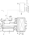
本実施形態について、図1〜図4を参照して説明する。図1に示すように、車両用空調装置1は、車室内を空調する室内空調ユニット10、バッテリ51が搭載されたバッテリユニット50、および制御装置100を備えている。
(1st Embodiment)
This embodiment will be described with reference to FIGS. As shown in FIG. 1, the
室内空調ユニット10は、車室内の前部に配置されるインストルメントパネルに内側等に配置されている。室内空調ユニット10は、空調ケース12、図示しない内外気ドア、蒸発器16、室内用送風機18、図示しないヒータコア、図示しないエアミックスドア等を備えている。
The indoor air-
空調ケース12は、室内空調ユニット10の外殻を構成すると共に、その内部に車室内へ向かう空気が流れる通風路13が形成されている。空調ケース12は、ある程度の弾性を有し、強度的に優れた樹脂(例えば、ポリプロピレン)にて成形されている。なお、空調ケース12は、樹脂成形上の都合、内部部品の組付上の都合等から、実際には複数の分割ケースの組付体として構成されている。具体的には、空調ケース12は、ネジ、クリップ等の締結部材によって複数の分割ケースを締結することで構成されている。
The air-
図示しないが、空調ケース12には、室内用送風機18の空気流れ上流側に、車室外空気(すなわち、外気)を導入する外気導入部、車室内空気(すなわち、内気)を導入する内気導入部が隣接して形成されている。また、図示しないが、空調ケース12の内部には、外気導入部および内気導入部の開口割合を調整する内外気ドアが配置されている。
Although not shown, the air-
図示しないが、空調ケース12には、室内用送風機18の空気流れ下流側に、デフロスタ開口部、フェイス開口部、およびフット開口部が形成されている。デフロスタ開口部は、車両の窓ガラスの内側に向けて空気を供給するための開口部である。フェイス開口部は、車室内の乗員の上半身側に向けて空気を供給するための開口部である。フット開口部は、車室内の乗員の下半身側に向けて空気を供給するための開口部である。なお、図示しないが、空調ケース12の内部には、前述の各開口部の開閉状態を調整する吹出モードドアが設けられている。
Although not shown, a defroster opening, a face opening, and a foot opening are formed in the
空調ケース12には、外気導入部または内気導入部から導入された空気に含まれる塵等の異物を捕集するエアフィルタ14が配置されている。エアフィルタ14は、図示しないフィルタ枠、フィルタエレメント等で構成されている。
In the
空調ケース12には、その内部を流れる空気を冷却する冷却用熱交換器として機能する蒸発器16が収容されている。蒸発器16は、エアフィルタ14を通過した空気が通過するように、エアフィルタ14の空気流れ下流側に配置されている。
The
本実施形態の蒸発器16は、蒸気圧縮式の冷凍サイクルにおける低圧側の熱交換器で構成されている。すなわち、蒸発器16は、内部を流れる低温低圧の流体(すなわち、冷媒)を空気と熱交換させて蒸発させることで、空調ケース12の内部を流れる空気を冷却する熱交換器である。蒸発器16は、外形状が矩形状の薄型形状となっている。
The
空調ケース12には、車室内へ向かう気流を発生させる室内用送風機18が配置されている。室内用送風機18は、空調ケース12の内部における蒸発器16よりも空気流れ下流側に配置されている。室内用送風機18は、ファン181、ファン181を回転駆動する電動機182を備える。本実施形態の室内用送風機18は、ファン軸心CLの延伸方向が蒸発器16の厚み方向に沿って延びるように配置されている。
In the
ファン181は、ファン軸心CLの延伸方向から吸い込んだ空気をファン軸心CLに交差する方向に吹き出す構成となっている。本実施形態のファン181は、軸流ファンよりも動圧が小さく、静圧が大きくなる特性を有する遠心ファンで構成されている。
The
ここで、遠心ファンは、羽根形状によってシロッコファン、ラジアルファン、ターボファンに区分される。本実施形態のファン181は、遠心ファンの中でも高い静圧が得られるターボファンで構成されている。なお、遠心ファンは、ターボファン以外のシロッコファン、ラジアルファンで構成されていてもよい。
Here, the centrifugal fan is classified into a sirocco fan, a radial fan, and a turbo fan according to the blade shape. The
空調ケース12には、ファン181を収容するファン収容部15が形成されている。ファン収容部15は、空調ケース12における蒸発器16の空気流れ下流側に形成されている。
The air-
ファン収容部15には、ファン181の内部に空気を導く空気吸入部151が設定されている。また、ファン収容部15には、ファン181の空気吹出側にファン181の内部で生じた気流を吹き出す空気吹出部152が設定されている。
An
本実施形態のファン収容部15は、通風路13における室内用送風機18の空気流れ上流側の上流側空間131と室内用送風機18の空気流れ下流側の下流側空間132とを区画する区画部153を含んで構成されている。
The
本実施形態の室内用送風機18は、蒸発器16を通過した空気が空気吸入部151に導かれ易くなるように、空気吸入部151が蒸発器16における空気の流出面161に対向した配置形態となっている。換言すれば、本実施形態の蒸発器16は、空気吸入部151から視認可能なように、空気の流出面161が空気吸入部151と対向した状態で配置されている。
The
空調ケース12には、空気吹出部152の空気流れ下流側に図示しないヒータコアが配置されている。ヒータコアは、蒸発器16を通過した空気を加熱する加熱用熱交換器である。ヒータコアとしては、例えば、内燃機関を冷却する冷却水を熱源として、蒸発器16を通過した空気を加熱する熱交換器を採用することができる。
In the air-
また、空調ケース12には、空気吹出部152の下流側に図示しない冷風バイパス通路が形成されている。冷風バイパス通路は、室内用送風機18から吹き出された気流をヒータコアを迂回して流す通路である。
In the
さらに、空調ケース12には、エアミックスドアが配置されている。エアミックスドアは、ヒータコアを通過する空気および冷風バイパス通路を通過する空気の風量割合を調整する部材である。なお、空調ケース12には、ヒータコアおよび冷風バイパス通路の空気流れ下流側に、前述したデフロスタ開口部、フェイス開口部、およびフット開口部が形成されている。
Further, an air mix door is arranged in the
ここで、空調ケース12には、蒸発器16から室内用送風機18の空気吸入側に至る通風路13を形成する中間壁面部121に中間開口部122が形成されている。中間開口部122は、蒸発器16にて冷却された冷風を後述するバッテリ収容空間52aに導出するための開口部である。中間開口部122は、中間壁面部121における蒸発器16にて生じた凝縮水が付着し難い部位に形成されていることが望ましい。中間開口部122には、空調ケース12の内部と後述するバッテリ収容空間52aとを連通させる連通ダクト30が接続されている。
Here, in the air-
連通ダクト30は、一端側が空調ケース12における室内用送風機18の空気流れ上流側に位置する部位、すなわち、中間壁面部121の中間開口部122に接続されている。また、連通ダクト30は、他端側がバッテリケース52に形成された空気吸込口521に接続されている。
One end of the
続いて、バッテリユニット50について説明する。バッテリユニット50は、車両の床下に搭載されている。なお、バッテリユニット50の搭載位置は、車両の床下に限らず、車両のトランクルームやシートの下方側に搭載されていてもよい。
Next, the
バッテリユニット50は、室内空調ユニット10で生成された冷風を利用してバッテリ51を冷却することが可能に構成されている。バッテリユニット50は、バッテリ51、バッテリケース52、排気ダクト54、バッテリ用送風機56を含んで構成されている。
The
バッテリ51は、車載機器に対して所定の高電圧を供給するものである。バッテリ51は、例えば、車両走行時の駆動力を発生させる走行用モータに電力を供給する大容量の電池で構成されている。
The
バッテリ51は、充放電可能な二次電池で構成されている。バッテリ51は、例えば、リチウムイオン電池等の電池セルが電気的に直列または並列に接続された組電池として構成されている。
The
バッテリケース52は、バッテリユニット50の外殻を構成すると共に、その内部にバッテリ51を収容するバッテリ収容空間52aが形成されている。バッテリ収容空間52aは、連通ダクト30を介して、室内空調ユニット10で生成された冷風が流れる通風路としても機能する。
The
バッテリケース52には、バッテリ収容空間52aに空気を導入する空気吸込口521、およびバッテリ収容空間52aから空気を導出する空気排出口522が形成されている。空気吸込口521には、連通ダクト30が接続されている。また、空気排出口522には、バッテリ収容空間52aの空気を車両外部に導く排気ダクト54が接続されている。
The
バッテリ収容空間52aには、バッテリ用送風機56が配置されている。バッテリ用送風機56は、連通ダクト30を介して空調ケース12の内部を流れる空気をバッテリ収容空間52aに導く送風機である。
A
本実施形態のバッテリ用送風機56は、バッテリ収容空間52aにおけるバッテリ51よりも空気流れ上流側に配置されている。具体的には、バッテリ用送風機56は、バッテリ収容空間52aのうち、バッテリ51よりも連通ダクト30に近い位置に配置されている。換言すれば、バッテリ用送風機56は、バッテリ51よりも排気ダクト54から離れた位置に配置されている。
The
バッテリ用送風機56は、図示しないファンおよび電動機を備える電動送風機で構成されている。バッテリ用送風機56のファンは、例えば、軸流ファンで構成されている。なお、バッテリ用送風機56のファンは、軸流ファンに限らず、遠心ファン等で構成されていてもよい。
The
続いて、車両用空調装置1の電子制御部を構成する制御装置100について説明する。制御装置100は、CPU、記憶部等を含む周知のマイクロコンピュータ、およびその周辺回路で構成されている。制御装置100は、記憶部等に記憶された制御プログラムに基づいて、各種演算、処理を行う装置である。なお、制御装置100の記憶部は、非遷移的実体的記憶媒体で構成されている。
Subsequently, the
制御装置100の入力側には、内気温度を検出する内気センサ101、外気温度を検出する外気センサ102、車室内への日射量を検出する日射センサ103等の空調用のセンサ群が接続されている。
An input side of the
また、制御装置100の入力側には、バッテリ51の温度を検出するバッテリ温度センサ104が接続されている。バッテリ温度センサ104は、例えば、バッテリ51の表面温度を検出する温度センサで構成されている。
A
さらに、制御装置100の入力側には、乗員が操作する操作部110が接続されている。操作部110には、空調作動スイッチ、車室内の設定温度を設定する温度設定スイッチ等が設けられている。
Further, an
一方、制御装置100の出力側には、制御装置100から出力される制御信号によって作動が制御される制御対象機器が接続されている。具体的には、制御装置100には、制御対象機器として室内用送風機18、バッテリ用送風機56等が接続されている。
On the other hand, the output side of the
ここで、制御装置100は、その出力側に接続された制御対象機器を制御するハードウェアおよびソフトフェアで構成される複数の制御部が集約されている。本実施形態の制御装置100は、例えば、単に車室内を空調する室内空調モード、車室内の空調およびバッテリ51の冷却を並行して実施するバッテリ冷却モード等の運転モードを切替制御するモード制御部100aが集約されている。
Here, in the
次に、上述の如く構成される車両用空調装置1の作動について説明する。車両用空調装置1は、運転モードが室内空調モードおよびバッテリ冷却モードに切替可能となっている。具体的には、車両用空調装置1は、電源供給された状態で操作部110の空調作動スイッチがオンされると、制御装置100が、運転モードを切り替えるモード切替処理を実行する。
Next, the operation of the
本実施形態では、制御装置100が実行するモード切替処理の概要について、図2に示すフローチャートを参照して説明する。図2に示すモード切替処理の各制御ステップは、制御装置100が実行する各種機能を実現する機能実現部を構成している。
In the present embodiment, an outline of a mode switching process executed by the
図2に示すように、制御装置100は、ステップS10にて、各種センサ101〜104のセンサ信号および操作部110の操作信号を読み込む。続いて、制御装置100は、ステップS20にて、バッテリ温度センサ104で検出されたバッテリ温度が適正上限温度以下であるか否かを判定する。
As shown in FIG. 2, the
ここで、バッテリ51は、充電時や図示しない走行用モータへ電力を供給する放電時に発熱を生じて高温となることがある。バッテリ51は、その温度が所定の温度(例えば、40℃)を超えると、性能低下や劣化を生じてしまう。このことを考慮して、適正上限温度は、例えば、40℃以下に設定される。なお、適正上限温度は、バッテリ51を構成する電池の種類に応じて適宜設定することが望ましい。
Here, the
ステップS20の判定処理の結果、バッテリ温度が適正上限温度以下であると判定された場合、バッテリ51の冷却が不要と考えられるので、制御装置100は、ステップS30にて運転モードを室内空調モードに決定する。
As a result of the determination processing in step S20, when it is determined that the battery temperature is equal to or lower than the appropriate upper limit temperature, it is considered that cooling of
制御装置100は、室内空調モード時に、バッテリ用送風機56の作動を停止した状態で、室内用送風機18を稼働状態に制御する。制御装置100は、室内空調モード時に、車室内へ吹き出す空気の目標温度である目標吹出温度TAOに基づいて、室内用送風機18等の制御対象機器の作動を制御する。
The
具体的には、制御装置100は、室内空調モード時に、車室内へ吹き出す空気の目標温度である目標吹出温度TAOを算出する。なお、制御装置100は、TAOを例えば以下の[数1]により算出する。
TAO=Kset×Tset−Kr×Tr−Kam×Tam−Ks×Ts+C…[数1]
但し、Tsetは、温度設定スイッチに設定された設定温度、Trは、内気センサ101の検出値、Tamは外気センサ102の検出値、Tsは日射センサ103の検出値である。また、Kset、Kr、Kam、Ksは、制御ゲインであり、Cは補正用の定数である。
Specifically,
TAO = Kset × Tset−Kr × Tr−Kam × Tam−Ks × Ts + C [Equation 1]
Here, Tset is a set temperature set in the temperature setting switch, Tr is a detection value of the
そして、制御装置100は、TAO等に基づいて、予め記憶部に記憶された制御マップを参照して室内用送風機18等の制御対象機器への作動状態を決定する。制御装置100は、例えば、TAOが極高温域や極低温域となって高い空調性能が必要となる際に、最大風量となるように室内用送風機18の回転数を高回転数に決定する。また、制御装置100は、例えば、TAOと車室内の温度との温度差が縮小されるに伴って風量が低下するように室内用送風機18の回転数を決定する。
Then, based on TAO or the like,
室内空調モード時には、制御装置100によって、バッテリ用送風機56の作動が停止された状態で、室内用送風機18が稼働状態に制御されることで、空調ケース12の内部に車室内へ向かう気流が発生する。
In the indoor air-conditioning mode, the
これにより、通風路13における上流側空間131では、外気導入部または内気導入部から導入された気流が、エアフィルタ14を経由して蒸発器16に流入する。この気流は、蒸発器16にて所定の温度まで冷却された後、空気吸入部151から室内用送風機18に吸い込まれる。室内用送風機18に吸い込まれた空気は、ファン181の内側から径方向外側に向かって吹き出される。この気流は、通風路13における下流側空間132を流れる。下流側空間132では、図示しないヒータコアまたは冷風バイパス通路を通過した後、各開口部のいずれかを介して車室内に吹き出される。
Thus, in the
一方、ステップS20の判定処理の結果、バッテリ温度が適正上限温度を超えていると判定された場合、バッテリ51の冷却が必要と考えられるので、制御装置100は、ステップS40にて運転モードをバッテリ冷却モードに決定する。
On the other hand, when it is determined that the battery temperature exceeds the appropriate upper limit temperature as a result of the determination processing in step S20, it is considered that the
制御装置100は、バッテリ冷却モード時に、室内用送風機18およびバッテリ用送風機56の双方を稼働状態に制御する。なお、バッテリ冷却モード時における室内空調ユニット10側の制御対象機器については、制御装置100によって、室内空調モード時と同様の作動状態に制御される。
The
制御装置100は、バッテリ冷却モード時に、回転数が予め定めた基準回転数となるようにバッテリ用送風機56を制御する。なお、制御装置100は、バッテリ冷却モード時に、バッテリ温度が高くなるに伴って回転数が増加するようにバッテリ用送風機56を制御する構成となっていてもよい。
The
バッテリ冷却モード時には、制御装置100によって、室内用送風機18およびバッテリ用送風機56の双方が稼働状態に制御されることで、空調ケース12の内部に車室内へ向かう気流、およびバッテリ収容空間52aに向かう気流が発生する。
In the battery cooling mode, the
これにより、通風路13における上流側空間131では、外気導入部または内気導入部から導入された気流が、図3の矢印AFEで示すように、エアフィルタ14を経由して蒸発器16に流入し、蒸発器16にて所定の温度まで冷却される。
Thereby, in the
そして、蒸発器16にて冷却された空気は、図3の矢印AFSで示すように空気吸入部151から室内用送風機18に吸い込まれると共に、図3の矢印AFB1で示すように連通ダクト30を介してバッテリ収容空間52aのバッテリ用送風機56に吸い込まれる。
Then, the air cooled by the
室内用送風機18に吸い込まれた空気は、図3の矢印AFDに示すように、ファン181の内側から径方向外側に向かって吹き出される。この気流は、図示しないヒータコアまたは冷風バイパス通路を通過した後、各開口部のいずれかを介して車室内に吹き出される。
The air sucked into the
一方、バッテリ用送風機56に吸い込まれた空気は、図3の矢印AFB2に示すように、バッテリ用送風機56の空気流れ下流側に位置するバッテリ51に対して吹き出される。これにより、バッテリ51が冷却される。そして、バッテリ収容空間52aにおいてバッテリ51から吸熱した空気は、図3の矢印AFB3に示すように、排気ダクト54を介して車両外部に排出される。
On the other hand, the air sucked into the
ここで、本実施形態の車両用空調装置1の比較例について、図4を参照して説明する。図4は、比較例の車両用空調装置CEの模式的な断面図である。なお、説明の便宜上、図4では、比較例の車両用空調装置CEについて本実施形態の車両用空調装置1と同様の構成について同一の参照符号を付している。
Here, a comparative example of the
図4に示すように、比較例の車両用空調装置CEの室内空調ユニットHUは、空調ケースHCにおける室内用送風機BFが蒸発器16の空気流れ上流側に配置されている。そして、空調ケースHCには、蒸発器16の空気流れ下流側に、蒸発器16を通過した空気をバッテリ収容空間52aに導く連通ダクトCDが接続されている。
As shown in FIG. 4, in the indoor air conditioning unit HU of the vehicle air conditioner CE of the comparative example, the indoor blower BF in the air conditioning case HC is disposed upstream of the
また、比較例の車両用空調装置CEのバッテリユニットBUには、バッテリBTに空気を供給する専用の送風機が設けられていない。その他の構成は、本実施形態の車両用空調装置1と同様である。
Further, the battery unit BU of the vehicle air conditioner CE of the comparative example is not provided with a dedicated blower for supplying air to the battery BT. Other configurations are the same as those of the
比較例の車両用空調装置CEでは、室内用送風機BFが作動すると、室内用送風機BFから吹き出された空気が蒸発器16に流入する。そして、蒸発器16を通過した空気は、一部が連通ダクトCDを介してバッテリBTに供給され、残りが図示しないヒータコアまたは冷風バイパス通路を通過した後、各開口部のいずれかを介して車室内に吹き出される。
In the vehicle air conditioner CE of the comparative example, when the indoor blower BF operates, the air blown out from the indoor blower BF flows into the
比較例の車両用空調装置CEの如く、室内用送風機BFの空気流れ下流側にバッテリ収容空間52aに連通する連通ダクトCDを接続する構成では、室内用送風機BFで発生した気流の一部がバッテリユニットBU側に流れる。このため、比較例の車両用空調装置CEでは、バッテリBTを冷却する際に、車室内に吹き出す風量が低下してしまう。このことは、乗員の空調フィーリングが悪化する要因となることから好ましくない。
As in the vehicle air conditioner CE of the comparative example, in the configuration in which the communication duct CD communicating with the
また、例えば、エアミックス方式の室内空調ユニットHUでは、蒸発器16で冷却された冷風をバッテリBT側に導入すると、室内空調ユニットHUにおける冷風と温風との混合割合が変化してしまう。すなわち、エアミックス方式の室内空調ユニットHUでは、車室内へ吹き出す空気の温度を適切に調整できなくなってしまう。
Further, for example, in the air-mix type indoor air conditioning unit HU, when the cool air cooled by the
このように、比較例の車両用空調装置CEでは、バッテリBTの冷却と車室内の空調とを並行して実施する場合に、車室内の空調性能が低下してしまう。 As described above, in the vehicle air conditioner CE of the comparative example, when the cooling of the battery BT and the air conditioning of the vehicle interior are performed in parallel, the air conditioning performance of the vehicle interior deteriorates.
これに対して、本実施形態の車両用空調装置1は、空調ケース12の内部に室内用送風機18が配置されると共に、バッテリ収容空間52aにバッテリ用送風機56が配置されている。
On the other hand, in the
加えて、本実施形態の車両用空調装置1は、バッテリ収容空間52aに冷風を導入する連通ダクト30が、空調ケース12における室内用送風機18の空気流れ上流側の部位(すなわち、中間壁面部121)に接続されている。
In addition, in the
これによれば、室内用送風機18によって車室内の空調に必要な風量を確保しつつ、バッテリ用送風機56によってバッテリ51の冷却に必要な風量を確保することができる。すなわち、本実施形態の車両用空調装置1は、バッテリ51の冷却に必要な風量と車室内の空調に必要とされる風量とを独立して確保することができる。従って、本実施形態の車両用空調装置1は、バッテリ51の冷却と車室内の空調とを並行して実施する際に車室内の空調性能が低下することを抑制可能となる。
According to this, the air flow required for cooling the
特に、本実施形態の連通ダクト30は、空調ケース12における蒸発器16と室内用送風機18との間に接続されているので、バッテリ用送風機56によって蒸発器16にて冷却された冷風をバッテリ収容空間52aに導入することができる。これによれば、室内空調ユニット10の蒸発器16で冷却された冷風によってバッテリ51を充分に冷却することができる。
In particular, since the
(第2実施形態)
次に、第2実施形態について、図5を参照して説明する。本実施形態では、バッテリユニット50におけるバッテリ用送風機56の搭載位置が、第1実施形態におけるバッテリ用送風機56の搭載位置と相違している。
(2nd Embodiment)
Next, a second embodiment will be described with reference to FIG. In the present embodiment, the mounting position of the
図5に示すように、本実施形態のバッテリ用送風機56は、バッテリ収容空間52aにおいて、バッテリ51の空気流れ下流側に配置されている。具体的には、本実施形態のバッテリ用送風機56は、バッテリ51よりも排気ダクト54に近い位置に配置されている。換言すれば、本実施形態のバッテリ用送風機56は、バッテリ51よりも連通ダクト30から離れた位置に配置されている。
As shown in FIG. 5, the
本実施形態の車両用空調装置1における他の構成は、第1実施形態と同様である。本実施形態の車両用空調装置1は、第1実施形態と共通の構成から奏される作用効果を第1実施形態と同様に得ることができる。
Other configurations of the
ここで、バッテリ用送風機56は、その作動時に電動機等が発熱する。このため、バッテリ用送風機56がバッテリ51よりも空気流れ上流側に配置されていると、バッテリ用送風機56の熱によってバッテリ51に供給される空気の温度が上昇してしまうことが懸念される。
Here, when the
これに対して、本実施形態の車両用空調装置1は、バッテリ用送風機56が、バッテリ収容空間52aにおいて、バッテリ51の空気流れ下流側に配置されている。これによると、バッテリ用送風機56の作動時に生ずる熱によって、バッテリ51に供給される空気の温度が上昇してしまうことを防止することができるので、効率よくバッテリ51を冷却することが可能となる。
On the other hand, in the
(第3実施形態)
次に、第3実施形態について、図6を参照して説明する。本実施形態では、空調ケース12の内部に内気が流れる内気通風路13Aと外気が流れる外気通風路13Bが形成されている点が第2実施形態と相違している。
(Third embodiment)
Next, a third embodiment will be described with reference to FIG. This embodiment is different from the second embodiment in that an
図6に示すように、空調ケース12には、その内部を内気通風路13Aと外気通風路13Bに仕切る第1隔壁部124および第2隔壁部126が設けられている。第1隔壁部124は、空調ケース12におけるエアフィルタ14の空気流れ上流側に設けられている。また、第2隔壁部126は、空調ケース12における蒸発器16と室内用送風機18との間に設けられている。
As shown in FIG. 6, the air-
また、本実施形態の室内用送風機18は、単一の電動機182にて第1ファン181Aおよび第2ファン181Bという2つのファンを駆動するダブルファン型の送風機で構成されている。第1ファン181Aは、内気通風路13Aに気流を発生させるファンである。また、第2ファン181Bは、外気通風路13Bに気流を発生させるファンである。
In addition, the
そして、本実施形態のファン収容部15には、第1ファン181Aの内側に空気を導く第1空気吸入部151Aが設定され、第2ファン181Bの内側に空気を導く第2空気吸入部151Bが設定されている。また、ファン収容部15には、第1ファン181Aの内部で生じた気流を吹き出す第1空気吹出部152Aが設定され、第2ファン181Bの内部で生じた気流を吹き出す第2空気吹出部152Bが設定されている。
In the
さらに、室内用送風機18は、蒸発器16を通過した空気が、第1空気吸入部151Aおよび第2空気吸入部151Bの一方に偏って流れないように、各空気吸入部151A、151Bの双方が蒸発器16の流出面161に対向しない配置形態となっている。換言すれば、本実施形態の蒸発器16は、各空気吸入部151A、151Bから視認できないようように、空気の流出面161が空気吸入部151と対向しない状態で配置されている。
Further, both of the
なお、本実施形態の空調ケース12は、ファン収容部15によって、内気通風路13Aにおける室内用送風機18の空気流れ上流側の第1上流側空間131Aと室内用送風機18の空気流れ下流側の第1下流側空間132Aとに区画されている。また、本実施形態の空調ケース12は、ファン収容部15によって、外気通風路13Bにおける室内用送風機18の空気流れ上流側の第2上流側空間131Bと室内用送風機18の空気流れ下流側の第2下流側空間132Bとに区画されている。
The air-
ここで、空調ケース12は、蒸発器16から第1ファン181Aに至る内気通風路13Aを形成する第1中間壁面部121A、および蒸発器16から第2ファン181Bに至る外気通風路13Bを形成する第2中間壁面部121Bを有している。
Here, the
そして、第2中間壁面部121Bには、蒸発器16にて冷却された冷風をバッテリ収容空間52aに導出するための中間開口部122が形成されている。そして、中間開口部122には、空調ケース12の内部とバッテリ収容空間52aとを連通させる連通ダクト30が接続されている。
The second
本実施形態の車両用空調装置1の他の構成は、前述の第2実施形態と同様である。本実施形態の車両用空調装置1は、第2実施形態と共通の構成から奏される作用効果を前述の実施形態と同様に得ることができる。
Other configurations of the
ここで、内気は、乗員の吐息等によって外気よりも湿度が高くなり易い傾向がある。このため、内気がバッテリ収容空間52aに導入される構成では、バッテリ51に結露が生じてしまうことが懸念される。
Here, the inside air tends to have a higher humidity than the outside air due to the occupant's exhalation or the like. For this reason, in a configuration in which inside air is introduced into the
また、冬期には、車室内の空調によって内気の温度が外気の温度よりも高くなる。このため、内気がバッテリ収容空間52aに導入される構成では、バッテリ51を充分に冷却することが困難となってしまうことが懸念される。
In winter, the temperature of the inside air becomes higher than the temperature of the outside air due to the air conditioning in the passenger compartment. Therefore, in a configuration in which the inside air is introduced into the
これに対して、本実施形態の車両用空調装置1は、バッテリ冷却モード時に、外気がバッテリ収容空間52aに導入されるように、連通ダクト30が空調ケース12における外気通風路13Bを形成する部位(すなわち、第2中間壁面部121B)に接続されている。
On the other hand, in the
これによると、図6の矢印AFB1で示すように、バッテリ収容空間52aには、内気に比べて低湿度となり易い外気が導入されるので、バッテリ冷却モード時にバッテリ51に結露が生じてしまうことを抑制することができる。また、冬期においては、バッテリ収容空間52aに内気に比べて低温となる外気が導入されるので、効率よくバッテリ51を冷却することが可能となる。
According to this, as shown by the arrow AFB1 in FIG. 6, since outside air, which tends to be lower in humidity than inside air, is introduced into the
(第4実施形態)
次に、第4実施形態について、図7〜図10を参照して説明する。本実施形態の車両用空調装置1は、空調ケース12の内部とバッテリ収容空間52aとの間の空気の流通状態を切り替える開閉ドア60が追加されている点が第1実施形態と相違している。
(Fourth embodiment)
Next, a fourth embodiment will be described with reference to FIGS. The
図7に示すように、本実施形態の車両用空調装置1には、連通ダクト30に開閉ドア60が配置されている。開閉ドア60は、空調ケース12の内部とバッテリ収容空間52aとの間の空気の流通を許容する許容状態と、空調ケース12の内部とバッテリ収容空間52aとの間の空気の流通を遮断する遮断状態とに切り替える切替機構として機能する。
As shown in FIG. 7, an opening / closing
具体的には、開閉ドア60は、空調ケース12の中間開口部122を開放する開放位置と、中間開口部122を閉鎖する閉鎖位置とに変位させることが可能に構成されている。より具体的には、本実施形態の開閉ドア60は、片持ち式のドアで構成されている。なお、開閉ドア60は、片持ち式のドアに限らず、バタフライドアやスライドドア等で構成されていてもよい。
Specifically, the opening / closing
また、本実施形態の開閉ドア60は、制御装置100からの制御信号に応じて開閉可能な電動ドアで構成されている。開閉ドア60は、制御装置100によって制御可能なように、制御装置100の出力側に接続されている。
Further, the opening / closing
本実施形態の車両用空調装置1における他の構成は、第1実施形態と同様である。以下、本実施形態の制御装置100が実行するモード切替処理の概要について、図8に示すフローチャートを参照して説明する。図8に示すモード切替処理の各制御ステップは、制御装置100が実行する各種機能を実現する機能実現部を構成している。
Other configurations of the
図8に示すように、制御装置100は、ステップS10にて、各種センサ101〜104のセンサ信号および操作部110の操作信号を読み込む。続いて、制御装置100は、ステップS20にて、バッテリ温度センサ104で検出されたバッテリ温度が適正上限温度以下であるか否かを判定する。
As shown in FIG. 8, the
ステップS20の判定処理の結果、バッテリ温度が適正上限温度以下であると判定された場合、バッテリ51の冷却が不要と考えられるので、制御装置100は、ステップS30Aにて運転モードを室内空調モードに決定する。
As a result of the determination processing in step S20, when it is determined that the battery temperature is equal to or lower than the appropriate upper limit temperature, it is considered that cooling of the
制御装置100は、室内空調モード時に、バッテリ用送風機56の作動を停止すると共に、開閉ドア60を中間開口部122の閉鎖位置に変位させた状態で、室内用送風機18を稼働状態に制御する。なお、制御装置100は、第1実施形態と同様に、目標吹出温度TAOに基づいて、室内用送風機18等の制御対象機器の作動を制御する。
In the indoor air-conditioning mode, the
室内空調モード時には、制御装置100によって、バッテリ用送風機56の作動が停止された状態で、室内用送風機18が稼働状態に制御されることで、空調ケース12の内部に車室内へ向かう気流が発生する。
In the indoor air-conditioning mode, the
これにより、通風路13における上流側空間131では、外気導入部または内気導入部から導入された気流が、図9の矢印AFEで示すように、エアフィルタ14を経由して蒸発器16に流入する。この気流は、蒸発器16にて所定の温度まで冷却された後、図9の矢印AFSで示すように、空気吸入部151から室内用送風機18に吸い込まれる。
Thereby, in the
この際、開閉ドア60が中間開口部122の開放位置にあると、連通ダクト30を介して、バッテリ収容空間52aの空気が、室内用送風機18に流入してしまう可能性がある。室内用送風機18にバッテリ収容空間52aの空気が吸い込まれることは、蒸発器16にて冷却された空気の温度が上昇する要因となることから、車室内の空調性能の低下が懸念される。
At this time, if the opening / closing
これに対して、本実施形態の車両用空調装置1は、室内空調モード時に、開閉ドア60を中間開口部122の閉鎖位置に変位させるので、室内用送風機18にバッテリ収容空間52aの空気が吸い込まれることがない。
On the other hand, in the
続いて、室内用送風機18に吸い込まれた空気は、図9の矢印AFDに示すように、ファン181の内側から径方向外側に向かって吹き出される。この気流は、図示しないヒータコアまたは冷風バイパス通路を通過した後、各開口部のいずれかを介して車室内に吹き出される。
Subsequently, the air sucked into the
一方、ステップS20の判定処理の結果、バッテリ温度が適正上限温度を超えていると判定された場合、バッテリ51の冷却が必要と考えられるので、制御装置100は、ステップS40Aにて運転モードをバッテリ冷却モードに決定する。
On the other hand, when it is determined that the battery temperature exceeds the appropriate upper limit temperature as a result of the determination processing in step S20, it is considered that the
制御装置100は、バッテリ冷却モード時に、開閉ドア60を中間開口部122の開放位置に変位させた状態で、室内用送風機18およびバッテリ用送風機56の双方を稼働状態に制御する。なお、制御装置100は、第1実施形態と同様に、室内用送風機18、バッテリ用送風機56等の制御対象機器の作動を制御する。
The
バッテリ冷却モード時には、制御装置100によって、室内用送風機18およびバッテリ用送風機56の双方が稼働状態に制御されることで、空調ケース12の内部に車室内へ向かう気流、およびバッテリ収容空間52aに向かう気流が発生する。
In the battery cooling mode, the
これにより、通風路13における上流側空間131では、外気導入部または内気導入部から導入された気流が、図10の矢印AFEで示すように、エアフィルタ14を経由して蒸発器16に流入し、蒸発器16にて所定の温度まで冷却される。そして、蒸発器16にて冷却された空気は、図10の矢印AFSで示すように空気吸入部151から室内用送風機18に吸い込まれる。
Thereby, in the
室内用送風機18に吸い込まれた空気は、図10の矢印AFDに示すように、ファン181の内側から径方向外側に向かって吹き出される。この気流は、図示しないヒータコアまたは冷風バイパス通路を通過した後、各開口部のいずれかを介して車室内に吹き出される。
The air sucked into the
ここで、バッテリ冷却モード時には、開閉ドア60を中間開口部122の開放位置に変位させるので、蒸発器16にて冷却された空気は、図10の矢印AFB1で示すように連通ダクト30を介してバッテリ収容空間52aのバッテリ用送風機56に吸い込まれる。
Here, in the battery cooling mode, since the opening / closing
バッテリ用送風機56に吸い込まれた空気は、図10の矢印AFB2に示すように、バッテリ用送風機56の空気流れ下流側に位置するバッテリ51に対して吹き出される。これにより、バッテリ51が冷却される。そして、バッテリ収容空間52aにおいてバッテリ51から吸熱した空気は、図10の矢印AFB3に示すように、排気ダクト54を介して車両外部に排出される。
The air sucked into the
本実施形態の車両用空調装置1は、基本構成が第1実施形態と共通しているので、第1実施形態で説明した作用効果を第1実施形態と同様に得ることができる。
The basic configuration of the
加えて、本実施形態の車両用空調装置1は、空調ケース12の内部とバッテリ収容空間52aとの間の空気の流通を許容する許容状態と、空気の流通を遮断する遮断状態とに切り替える切替機構として開閉ドア60を備えている。
In addition, the
これによれば、バッテリ用送風機56を停止してバッテリ51の冷却を行わない場合(すなわち、車室内の空調だけを実施している場合)に、バッテリ収容空間52aから空調ケース12の内部に空気が流れ込むことを防止することができる。これにより、車室内の空調だけを実施する場合に、車室内の空調性能の低下を抑制することができる。
According to this, when the
ここで、本実施形態では、第1実施形態で説明した車両用空調装置1に対して開閉ドア60を適用した構成を例示したが、開閉ドア60の適用対象は、第1実施形態に限定されない。開閉ドア60は、第2実施形態や第3実施形態で説明した車両用空調装置1に適用することが可能である。
Here, in the present embodiment, the configuration in which the opening / closing
本実施形態では、開閉ドア60によって中間開口部122を開閉する構成を例示したが、これに限定されない。開閉ドア60は、例えば、バッテリケース52の空気吸込口521を開閉するように構成されていてもよい。
In the present embodiment, the configuration in which the
また、本実施形態では、開閉ドア60が電動ドアで構成される例について説明したが、これに限定されない。開閉ドア60は、例えば、バッテリ用送風機56が停止している際に閉鎖位置に変位し、バッテリ用送風機56が稼働している際に開放位置に変位するように構成された機械式のドアで構成されていてもよい。
Further, in the present embodiment, an example in which the opening and closing
(他の実施形態)
以上、本発明の代表的な実施形態について説明したが、本発明は、上述の実施形態に限定されることなく、例えば、以下のように種々変形可能である。
(Other embodiments)
The representative embodiment of the present invention has been described above. However, the present invention is not limited to the above-described embodiment, and can be variously modified as follows, for example.
上述の各実施形態では、通風路13の上流側空間131に蒸発器16が配置される構成を例示したが、これに限定されない。室内空調ユニット10は、例えば、通風路13の下流側空間132に蒸発器16およびヒータコアの双方が配置される構成となっていてもよい。また、室内空調ユニット10は、例えば、通風路13の上流側空間131に蒸発器16およびヒータコアの双方が配置される構成となっていてもよい。
In each of the above-described embodiments, the configuration in which the
上述の各実施形態では、バッテリ用送風機56をバッテリ51の空気流れ上流側や、バッテリ51の空気流れ下流側に配置する例について説明したが、これに限定されない。バッテリ用送風機56は、例えば、空気流れに対して同様の位置となるように、バッテリ51に対して一体に取り付けられた構成となっていてもよい。
In each of the above-described embodiments, an example in which the
上述の各実施形態では、冷凍サイクルの蒸発器16によって空気を冷却する例について説明したが、これに限定されない。空気を冷却する冷却用熱交換器は、蒸発器16に限らず、例えば、内部に冷水が流通する熱交換器で構成されていてもよい。
In each of the above embodiments, an example in which air is cooled by the
上述の実施形態において、実施形態を構成する要素は、特に必須であると明示した場合および原理的に明らかに必須であると考えられる場合等を除き、必ずしも必須のものではないことは言うまでもない。 In the above-described embodiment, it goes without saying that the elements constituting the embodiment are not necessarily essential, unless otherwise clearly indicated as essential or in principle considered to be clearly essential.
上述の実施形態において、実施形態の構成要素の個数、数値、量、範囲等の数値が言及されている場合、特に必須であると明示した場合および原理的に明らかに特定の数に限定される場合等を除き、その特定の数に限定されない。 In the above-described embodiment, when a numerical value such as the number, numerical value, amount, range or the like of the constituent elements of the exemplary embodiment is referred to, it is particularly limited to a specific number when it is explicitly stated that it is essential and in principle. It is not limited to that particular number, except in such cases.
上述の実施形態において、構成要素等の形状、位置関係等に言及するときは、特に明示した場合および原理的に特定の形状、位置関係等に限定される場合等を除き、その形状、位置関係等に限定されない。 In the above embodiments, when referring to the shape, positional relationship, and the like of the components, the shape, positional relationship, and the like, unless otherwise specified and in principle limited to a specific shape, positional relationship, etc. It is not limited to the above.
(まとめ)
上述の実施形態の一部または全部で示された第1の観点によれば、車両用空調装置は、バッテリ収容空間に、連通ダクトを介して空調ケースの内部を流れる空気をバッテリ収容空間に導くバッテリ用送風機が配置されている。そして、連通ダクトは、空調ケースにおける室内用送風機の空気流れ上流側に位置する部位に接続されている。
(Summary)
According to the first aspect shown in part or all of the above-described embodiment, the vehicle air conditioner guides the air flowing inside the air conditioning case to the battery housing space through the communication duct to the battery housing space. A battery blower is arranged. The communication duct is connected to a portion of the air conditioning case that is located on the upstream side of the airflow of the indoor blower.
また、第2の観点によれば、車両用空調装置は、空調ケースの内部を流れる空気を冷却する冷却用熱交換器を備える。冷却用熱交換器は、室内用送風機よりも空気流れ上流側に配置されている。そして、連通ダクトは、空調ケースにおける冷却用熱交換器の空気流れ下流側であって室内用送風機の空気流れ上流側に位置する部位に接続されている。 According to the second aspect, the vehicle air conditioner includes a cooling heat exchanger that cools air flowing inside the air conditioning case. The cooling heat exchanger is disposed upstream of the indoor blower in the air flow. The communication duct is connected to a portion of the air conditioning case that is located on the downstream side of the air flow of the cooling heat exchanger and on the upstream side of the air flow of the indoor blower.
このように、空調ケースにおける冷却用熱交換器と室内用送風機との間に連通ダクトを接続すれば、バッテリ用送風機によって冷却用熱交換器で冷却された冷風をバッテリ収容空間に導入することができる。これによれば、冷却用熱交換器で冷却された冷風によってバッテリを充分に冷却することができる。 As described above, if the communication duct is connected between the cooling heat exchanger and the indoor blower in the air conditioning case, the cool air cooled by the cooling heat exchanger by the battery blower can be introduced into the battery housing space. it can. According to this, the battery can be sufficiently cooled by the cool air cooled by the cooling heat exchanger.
また、第3の観点によれば、車両用空調装置は、バッテリ用送風機が、バッテリ収容空間において、バッテリの空気流れ下流側に配置されている。これによると、バッテリ用送風機の作動時に生ずる熱によって、バッテリに供給される空気の温度が上昇してしまうことを防止することができるので、効率よくバッテリを冷却することが可能となる。 Further, according to the third aspect, in the vehicle air conditioner, the battery blower is disposed downstream of the air flow of the battery in the battery housing space. According to this, it is possible to prevent the temperature of the air supplied to the battery from increasing due to the heat generated when the battery blower operates, and thus it is possible to efficiently cool the battery.
また、第4の観点によれば、車両用空調装置は、空調ケースの内部に、車室外空気が流れる外気通風路、および車室内空気が流れる内気通風路が設定されている。そして、連通ダクトは、車室外空気がバッテリ収容空間に導入されるように、空調ケースにおける外気通風路を形成する部位に接続されている。 According to the fourth aspect, in the air conditioner for a vehicle, an outside air passage through which air outside the vehicle compartment flows and an inside air passage through which air inside the vehicle interior flows are set inside the air conditioning case. The communication duct is connected to a portion of the air-conditioning case that forms an outside air passage so that outside air from the vehicle compartment is introduced into the battery housing space.
これによると、バッテリ収容空間には、車室内空気に比べて低湿度となり易い車室外空気が導入されるので、バッテリの冷却時にバッテリに結露が生じてしまうことを抑制することができる。また、冬期においては、バッテリ収容空間に車室内空気に比べて低温となる車室外空気が導入されるので、効率よくバッテリを冷却することが可能となる。 According to this, the outside air, which tends to have a lower humidity than the air inside the vehicle, is introduced into the battery housing space, so that it is possible to suppress the occurrence of dew condensation on the battery when the battery is cooled. In winter, the outside air, which is lower in temperature than the air inside the vehicle, is introduced into the battery housing space, so that the battery can be efficiently cooled.
また、第5の観点によれば、車両用空調装置は、空調ケースの内部とバッテリ収容空間との間の空気の流通を許容する許容状態と、空調ケースの内部とバッテリ収容空間との間の空気の流通を遮断する遮断状態とに切り替える切替機構を備える。そして、切替機構は、バッテリ用送風機が稼働している際に許容状態に切り替わり、バッテリ用送風機が停止している際に遮断状態に切り替わるように構成されている。 Further, according to the fifth aspect, the vehicle air conditioner is configured such that the air conditioner allows the air to flow between the inside of the air conditioning case and the battery housing space, and the state between the inside of the air conditioning case and the battery housing space. A switching mechanism is provided for switching to a cutoff state for cutting off the flow of air. The switching mechanism is configured to switch to an allowable state when the battery blower is operating, and to switch to a cutoff state when the battery blower is stopped.
これによれば、バッテリ用送風機を停止してバッテリの冷却を行わない場合(すなわち、車室内の空調だけを実施している場合)に、バッテリ収容空間から空調ケースの内部に空気が流れ込むことを防止することができる。これにより、車室内の空調だけを実施する場合に、車室内の空調性能の低下を抑制することができる。 According to this, when the battery blower is stopped to cool the battery (that is, when only air conditioning in the vehicle compartment is performed), air flows from the battery housing space into the air conditioning case. Can be prevented. Thus, when only the air conditioning in the vehicle compartment is performed, it is possible to suppress a decrease in the air conditioning performance in the vehicle compartment.
1 車両用空調装置
12 空調ケース
13 通風路
13A 内気通風路
13B 外気通風路
18 室内用送風機
30 連通ダクト
51 バッテリ
52a バッテリ収容空間
56 バッテリ用送風機
DESCRIPTION OF
Claims (4)
内部に空気の通風路(13、13A、13B)が形成された空調ケース(12)と、
前記車室内へ向かう気流を発生させる室内用送風機(18)と、
前記空調ケースの内部と前記バッテリ収容空間とを連通させる連通ダクト(30)と、を備え、
前記バッテリ収容空間には、前記連通ダクトを介して前記空調ケースの内部を流れる空気を前記バッテリ収容空間に導くバッテリ用送風機(56)が配置されており、
前記空調ケースの内部には、車室外空気が流れる外気通風路(13B)、および車室内空気が流れる内気通風路(13A)が設定されており、
前記連通ダクトは、前記車室外空気が前記バッテリ収容空間に導入されるように、前記空調ケースにおける前記室内用送風機の空気流れ上流側に位置する部位であって、前記空調ケースにおける前記外気通風路を形成する部位(121B)に接続されている車両用空調装置。 A vehicle air conditioner for supplying air to a vehicle compartment and a battery storage space (52a) in which a battery (51) is stored,
An air conditioning case (12) in which air ventilation paths (13, 13A, 13B) are formed;
An indoor blower (18) for generating an airflow toward the vehicle interior;
A communication duct (30) for communicating the inside of the air conditioning case with the battery housing space,
A battery blower (56) that guides air flowing inside the air conditioning case through the communication duct to the battery storage space is disposed in the battery storage space,
Inside the air-conditioning case, an outside air ventilation passage (13B) through which air outside the vehicle compartment flows and an inside air ventilation passage (13A) through which air inside the vehicle interior flows are set,
The communication duct is a portion located on the airflow upstream side of the indoor blower in the air conditioning case so that the outside air of the vehicle is introduced into the battery housing space, and the outside air ventilation passage in the air conditioning case The air conditioner for a vehicle connected to the part (121B) that forms the vehicle.
前記冷却用熱交換器は、前記室内用送風機よりも空気流れ上流側に配置されており、
前記連通ダクトは、前記空調ケースにおける前記冷却用熱交換器の空気流れ下流側であって前記室内用送風機の空気流れ上流側に位置する部位に接続されている請求項1に記載の車両用空調装置。 A cooling heat exchanger (16) for cooling air flowing inside the air conditioning case;
The cooling heat exchanger is arranged on the airflow upstream side of the indoor blower,
2. The vehicle air conditioner according to claim 1, wherein the communication duct is connected to a portion of the air conditioning case located downstream of the air flow of the cooling heat exchanger and upstream of the air flow of the indoor blower. 3. apparatus.
前記切替機構は、前記バッテリ用送風機が稼働している際に前記許容状態に切り替わり、前記バッテリ用送風機が停止している際に前記遮断状態に切り替わるように構成されている請求項1ないし3のいずれか1つに記載の車両用空調装置。 Switching between an allowable state in which the flow of air between the inside of the air conditioning case and the battery housing space is allowed and a cutoff state in which the flow of air between the inside of the air conditioning case and the battery housing space is shut off A mechanism (60),
4. The switching mechanism according to claim 1, wherein the switching mechanism switches to the allowable state when the battery blower is operating, and switches to the cutoff state when the battery blower is stopped. 5 . The vehicle air conditioner according to any one of the above.
Priority Applications (3)
| Application Number | Priority Date | Filing Date | Title |
|---|---|---|---|
| JP2017017723A JP6658584B2 (en) | 2017-02-02 | 2017-02-02 | Vehicle air conditioner |
| PCT/JP2017/047108 WO2018142826A1 (en) | 2017-02-02 | 2017-12-27 | Vehicle air conditioner |
| EP17894735.4A EP3578396A4 (en) | 2017-02-02 | 2017-12-27 | Vehicle air conditioner |
Applications Claiming Priority (1)
| Application Number | Priority Date | Filing Date | Title |
|---|---|---|---|
| JP2017017723A JP6658584B2 (en) | 2017-02-02 | 2017-02-02 | Vehicle air conditioner |
Publications (3)
| Publication Number | Publication Date |
|---|---|
| JP2018122783A JP2018122783A (en) | 2018-08-09 |
| JP2018122783A5 JP2018122783A5 (en) | 2019-02-21 |
| JP6658584B2 true JP6658584B2 (en) | 2020-03-04 |
Family
ID=63039513
Family Applications (1)
| Application Number | Title | Priority Date | Filing Date |
|---|---|---|---|
| JP2017017723A Active JP6658584B2 (en) | 2017-02-02 | 2017-02-02 | Vehicle air conditioner |
Country Status (3)
| Country | Link |
|---|---|
| EP (1) | EP3578396A4 (en) |
| JP (1) | JP6658584B2 (en) |
| WO (1) | WO2018142826A1 (en) |
Family Cites Families (11)
| Publication number | Priority date | Publication date | Assignee | Title |
|---|---|---|---|---|
| JPS4827391Y1 (en) * | 1968-05-21 | 1973-08-13 | ||
| JPH0698887B2 (en) * | 1985-12-27 | 1994-12-07 | 日本電装株式会社 | Air conditioner for vehicle |
| JP2006143183A (en) * | 2004-10-18 | 2006-06-08 | Denso Corp | Battery cooling device for vehicle use |
| DE102005049200A1 (en) * | 2004-10-18 | 2006-05-11 | Denso Corp., Kariya | Battery cooling device for vehicle use |
| JP4466595B2 (en) * | 2006-03-28 | 2010-05-26 | トヨタ自動車株式会社 | COOLING SYSTEM, AUTOMOBILE MOUNTING THE SAME, AND COOLING SYSTEM CONTROL METHOD |
| JP4327823B2 (en) * | 2006-06-15 | 2009-09-09 | トヨタ自動車株式会社 | COOLING SYSTEM, AUTOMOBILE MOUNTING THE SAME, AND COOLING SYSTEM CONTROL METHOD |
| JP4788540B2 (en) * | 2006-09-14 | 2011-10-05 | トヨタ自動車株式会社 | Air conditioning system and air conditioning method |
| JP2008222041A (en) | 2007-03-13 | 2008-09-25 | Mazda Motor Corp | Battery cooling device for automobile |
| WO2012055367A1 (en) * | 2010-10-29 | 2012-05-03 | Valeo Automotive Air Conditionning Hubei Co., Ltd. | Heating, ventilating and air conditioning system for electric vehicle or hybrid electric vehicle |
| US10744901B2 (en) * | 2012-06-13 | 2020-08-18 | Ford Global Technologies, Llc | Cooling system having active cabin venting for a vehicle battery |
| JP2015003617A (en) * | 2013-06-20 | 2015-01-08 | 三菱自動車工業株式会社 | Air-conditioning system |
-
2017
- 2017-02-02 JP JP2017017723A patent/JP6658584B2/en active Active
- 2017-12-27 EP EP17894735.4A patent/EP3578396A4/en not_active Withdrawn
- 2017-12-27 WO PCT/JP2017/047108 patent/WO2018142826A1/en unknown
Also Published As
| Publication number | Publication date |
|---|---|
| JP2018122783A (en) | 2018-08-09 |
| WO2018142826A1 (en) | 2018-08-09 |
| EP3578396A1 (en) | 2019-12-11 |
| EP3578396A4 (en) | 2020-02-12 |
Similar Documents
| Publication | Publication Date | Title |
|---|---|---|
| JP6318854B2 (en) | Air conditioner for vehicles | |
| US9937768B2 (en) | Air conditioning device for vehicle | |
| JP3309779B2 (en) | Vehicle air conditioner | |
| JP5609764B2 (en) | Air conditioner for vehicles | |
| US11254187B2 (en) | Vehicular air conditioner | |
| CN109153308B (en) | Air conditioning unit for vehicle | |
| WO2016186170A1 (en) | Air conditioning device for vehicle | |
| US20090023374A1 (en) | Air passage opening and closing device | |
| JPH10230734A (en) | Air-conditioner for vehicle | |
| US10780761B2 (en) | Inside-outside air switching unit | |
| JP3978826B2 (en) | Air conditioner for vehicles | |
| US20190111768A1 (en) | Air conditioning apparatus for vehicle | |
| JP5626094B2 (en) | Air conditioner for vehicles | |
| JP2016064695A (en) | Air conditioner for vehicle | |
| US20040231834A1 (en) | Vehicle air conditioner | |
| JP5626095B2 (en) | Air conditioner for vehicles | |
| JP6658584B2 (en) | Vehicle air conditioner | |
| CN108778794B (en) | Air conditioner for vehicle | |
| JP3314692B2 (en) | Vehicle air conditioner | |
| WO2018047463A1 (en) | Vehicle air-conditioning device | |
| JP5476888B2 (en) | Air conditioner for vehicles | |
| JP3985629B2 (en) | Air conditioner for vehicles | |
| JP2022174554A (en) | Air conditioner for vehicle | |
| JP2009083763A (en) | Heating device for vehicle | |
| JP2012153331A (en) | Vehicular air conditioning device |
Legal Events
| Date | Code | Title | Description |
|---|---|---|---|
| A521 | Request for written amendment filed |
Free format text: JAPANESE INTERMEDIATE CODE: A523 Effective date: 20190109 |
|
| A621 | Written request for application examination |
Free format text: JAPANESE INTERMEDIATE CODE: A621 Effective date: 20190109 |
|
| TRDD | Decision of grant or rejection written | ||
| A01 | Written decision to grant a patent or to grant a registration (utility model) |
Free format text: JAPANESE INTERMEDIATE CODE: A01 Effective date: 20200107 |
|
| A61 | First payment of annual fees (during grant procedure) |
Free format text: JAPANESE INTERMEDIATE CODE: A61 Effective date: 20200120 |
|
| R151 | Written notification of patent or utility model registration |
Ref document number: 6658584 Country of ref document: JP Free format text: JAPANESE INTERMEDIATE CODE: R151 |
|
| R250 | Receipt of annual fees |
Free format text: JAPANESE INTERMEDIATE CODE: R250 |