JP6655921B2 - Communication system and control method thereof, image forming apparatus and control method thereof, and program - Google Patents
Communication system and control method thereof, image forming apparatus and control method thereof, and program Download PDFInfo
- Publication number
- JP6655921B2 JP6655921B2 JP2015180115A JP2015180115A JP6655921B2 JP 6655921 B2 JP6655921 B2 JP 6655921B2 JP 2015180115 A JP2015180115 A JP 2015180115A JP 2015180115 A JP2015180115 A JP 2015180115A JP 6655921 B2 JP6655921 B2 JP 6655921B2
- Authority
- JP
- Japan
- Prior art keywords
- terminal
- relay server
- information
- mfp
- request
- Prior art date
- Legal status (The legal status is an assumption and is not a legal conclusion. Google has not performed a legal analysis and makes no representation as to the accuracy of the status listed.)
- Active
Links
Images


Classifications
-
- H—ELECTRICITY
- H04—ELECTRIC COMMUNICATION TECHNIQUE
- H04N—PICTORIAL COMMUNICATION, e.g. TELEVISION
- H04N1/00—Scanning, transmission or reproduction of documents or the like, e.g. facsimile transmission; Details thereof
- H04N1/00962—Input arrangements for operating instructions or parameters, e.g. updating internal software
- H04N1/00973—Input arrangements for operating instructions or parameters, e.g. updating internal software from a remote device, e.g. receiving via the internet instructions input to a computer terminal
-
- H—ELECTRICITY
- H04—ELECTRIC COMMUNICATION TECHNIQUE
- H04N—PICTORIAL COMMUNICATION, e.g. TELEVISION
- H04N1/00—Scanning, transmission or reproduction of documents or the like, e.g. facsimile transmission; Details thereof
- H04N1/00127—Connection or combination of a still picture apparatus with another apparatus, e.g. for storage, processing or transmission of still picture signals or of information associated with a still picture
- H04N1/00204—Connection or combination of a still picture apparatus with another apparatus, e.g. for storage, processing or transmission of still picture signals or of information associated with a still picture with a digital computer or a digital computer system, e.g. an internet server
- H04N1/00244—Connection or combination of a still picture apparatus with another apparatus, e.g. for storage, processing or transmission of still picture signals or of information associated with a still picture with a digital computer or a digital computer system, e.g. an internet server with a server, e.g. an internet server
-
- G—PHYSICS
- G06—COMPUTING; CALCULATING OR COUNTING
- G06F—ELECTRIC DIGITAL DATA PROCESSING
- G06F11/00—Error detection; Error correction; Monitoring
- G06F11/07—Responding to the occurrence of a fault, e.g. fault tolerance
- G06F11/0703—Error or fault processing not based on redundancy, i.e. by taking additional measures to deal with the error or fault not making use of redundancy in operation, in hardware, or in data representation
- G06F11/0706—Error or fault processing not based on redundancy, i.e. by taking additional measures to deal with the error or fault not making use of redundancy in operation, in hardware, or in data representation the processing taking place on a specific hardware platform or in a specific software environment
- G06F11/0733—Error or fault processing not based on redundancy, i.e. by taking additional measures to deal with the error or fault not making use of redundancy in operation, in hardware, or in data representation the processing taking place on a specific hardware platform or in a specific software environment in a data processing system embedded in an image processing device, e.g. printer, facsimile, scanner
-
- H—ELECTRICITY
- H04—ELECTRIC COMMUNICATION TECHNIQUE
- H04L—TRANSMISSION OF DIGITAL INFORMATION, e.g. TELEGRAPHIC COMMUNICATION
- H04L41/00—Arrangements for maintenance, administration or management of data switching networks, e.g. of packet switching networks
- H04L41/50—Network service management, e.g. ensuring proper service fulfilment according to agreements
- H04L41/5061—Network service management, e.g. ensuring proper service fulfilment according to agreements characterised by the interaction between service providers and their network customers, e.g. customer relationship management
- H04L41/5074—Handling of user complaints or trouble tickets
-
- H—ELECTRICITY
- H04—ELECTRIC COMMUNICATION TECHNIQUE
- H04L—TRANSMISSION OF DIGITAL INFORMATION, e.g. TELEGRAPHIC COMMUNICATION
- H04L63/00—Network architectures or network communication protocols for network security
- H04L63/08—Network architectures or network communication protocols for network security for authentication of entities
- H04L63/083—Network architectures or network communication protocols for network security for authentication of entities using passwords
-
- H—ELECTRICITY
- H04—ELECTRIC COMMUNICATION TECHNIQUE
- H04L—TRANSMISSION OF DIGITAL INFORMATION, e.g. TELEGRAPHIC COMMUNICATION
- H04L63/00—Network architectures or network communication protocols for network security
- H04L63/10—Network architectures or network communication protocols for network security for controlling access to devices or network resources
- H04L63/102—Entity profiles
-
- H—ELECTRICITY
- H04—ELECTRIC COMMUNICATION TECHNIQUE
- H04L—TRANSMISSION OF DIGITAL INFORMATION, e.g. TELEGRAPHIC COMMUNICATION
- H04L67/00—Network arrangements or protocols for supporting network services or applications
- H04L67/14—Session management
-
- H—ELECTRICITY
- H04—ELECTRIC COMMUNICATION TECHNIQUE
- H04L—TRANSMISSION OF DIGITAL INFORMATION, e.g. TELEGRAPHIC COMMUNICATION
- H04L67/00—Network arrangements or protocols for supporting network services or applications
- H04L67/50—Network services
- H04L67/51—Discovery or management thereof, e.g. service location protocol [SLP] or web services
-
- H—ELECTRICITY
- H04—ELECTRIC COMMUNICATION TECHNIQUE
- H04N—PICTORIAL COMMUNICATION, e.g. TELEVISION
- H04N1/00—Scanning, transmission or reproduction of documents or the like, e.g. facsimile transmission; Details thereof
-
- H—ELECTRICITY
- H04—ELECTRIC COMMUNICATION TECHNIQUE
- H04N—PICTORIAL COMMUNICATION, e.g. TELEVISION
- H04N1/00—Scanning, transmission or reproduction of documents or the like, e.g. facsimile transmission; Details thereof
- H04N1/00127—Connection or combination of a still picture apparatus with another apparatus, e.g. for storage, processing or transmission of still picture signals or of information associated with a still picture
- H04N1/00344—Connection or combination of a still picture apparatus with another apparatus, e.g. for storage, processing or transmission of still picture signals or of information associated with a still picture with a management, maintenance, service or repair apparatus
-
- H—ELECTRICITY
- H04—ELECTRIC COMMUNICATION TECHNIQUE
- H04N—PICTORIAL COMMUNICATION, e.g. TELEVISION
- H04N1/00—Scanning, transmission or reproduction of documents or the like, e.g. facsimile transmission; Details thereof
- H04N1/32—Circuits or arrangements for control or supervision between transmitter and receiver or between image input and image output device, e.g. between a still-image camera and its memory or between a still-image camera and a printer device
- H04N1/32358—Circuits or arrangements for control or supervision between transmitter and receiver or between image input and image output device, e.g. between a still-image camera and its memory or between a still-image camera and a printer device using picture signal storage, e.g. at transmitter
- H04N1/324—Circuits or arrangements for control or supervision between transmitter and receiver or between image input and image output device, e.g. between a still-image camera and its memory or between a still-image camera and a printer device using picture signal storage, e.g. at transmitter intermediate the transmitter and receiver terminals, e.g. at an exchange
- H04N1/32406—Circuits or arrangements for control or supervision between transmitter and receiver or between image input and image output device, e.g. between a still-image camera and its memory or between a still-image camera and a printer device using picture signal storage, e.g. at transmitter intermediate the transmitter and receiver terminals, e.g. at an exchange in connection with routing or relaying, e.g. using a fax-server or a store-and-forward facility
-
- H—ELECTRICITY
- H04—ELECTRIC COMMUNICATION TECHNIQUE
- H04L—TRANSMISSION OF DIGITAL INFORMATION, e.g. TELEGRAPHIC COMMUNICATION
- H04L63/00—Network architectures or network communication protocols for network security
- H04L63/16—Implementing security features at a particular protocol layer
- H04L63/168—Implementing security features at a particular protocol layer above the transport layer
-
- H—ELECTRICITY
- H04—ELECTRIC COMMUNICATION TECHNIQUE
- H04L—TRANSMISSION OF DIGITAL INFORMATION, e.g. TELEGRAPHIC COMMUNICATION
- H04L67/00—Network arrangements or protocols for supporting network services or applications
- H04L67/01—Protocols
- H04L67/10—Protocols in which an application is distributed across nodes in the network
-
- H—ELECTRICITY
- H04—ELECTRIC COMMUNICATION TECHNIQUE
- H04N—PICTORIAL COMMUNICATION, e.g. TELEVISION
- H04N2201/00—Indexing scheme relating to scanning, transmission or reproduction of documents or the like, and to details thereof
- H04N2201/0077—Types of the still picture apparatus
- H04N2201/0094—Multifunctional device, i.e. a device capable of all of reading, reproducing, copying, facsimile transception, file transception
Description
本発明は、通信システムとその制御方法、画像形成装置とその制御方法、及びプログラムに関する。 The present invention relates to a communication system and its control method, an image forming apparatus and its control method, and a program.
製品のトラブルに対する対処法が複雑化するのに伴い、顧客が直接、メーカのコールセンターに電話などで質問してトラブルに対処することが頻繁に行われている。また特許文献1では、画像形成装置とコールセンター間でのトラブル対処を迅速に行うための、音声や動画通信、遠隔操作による遠隔保守サービスが提案されている。この遠隔保守サービスでは、支援を受ける画像形成装置と、支援を行うコールセンターの情報処理装置とは、通常、それぞれ別のファイアウォールの中にある。
As the method of dealing with product troubles is becoming more complicated, customers frequently deal with the troubles by directly asking the call center of the manufacturer by telephone or the like.
特許文献2では、画像形成装置と情報処理装置とが通信を行うために、インターネット上に両者の通信を中継する中継サーバを設置することが提案されている。このような中継サーバを設置することによって、それぞれが別のファイアウォール内にある装置同士の通信が可能となる。
特許文献2に記載の技術を、特許文献1の遠隔保守サービスに適用する場合、顧客からの遠隔保守サービスの開始要求を受けると、画像形成装置とコールセンターが中継サーバに接続する必要がある。またこのとき、中継サーバに接続された画像形成装置が、遠隔保守サービスの契約がなされている画像形成装置であるかを確認し、認証する必要がある。これを実現するためには、遠隔保守サービスの適用対象となる全ての画像形成装置を対象として、それぞれがどの販売組織に属しているか、どのような契約がなされているかの情報が適切に管理されている必要がある。
When the technology described in
一般的に、コールセンターは画像形成装置の販売組織毎に運営される。よって、中継サーバは、中継サーバの負荷軽減やセキュリティのために販売組織ごとに用意され、1台とは限らず、複数台設置される。ここでコールセンターは、自らが属する販売組織が接続する中継サーバの情報を把握しているため、適切な中継サーバに接続できる。 Generally, a call center is operated for each sales organization of an image forming apparatus. Therefore, the relay server is prepared for each sales organization in order to reduce the load on the relay server and for security, and not limited to one, but a plurality of relay servers are installed. Here, since the call center knows the information of the relay server to which the sales organization to which the call center belongs connects, the call center can connect to an appropriate relay server.
一方、画像形成装置は、その画像形成装置を管理している販売組織の中継サーバへ接続するための情報を通常知らない。そのため、例えば画像形成装置の初期設置時等において、サービスマンが中継サーバの情報を設定する作業が必要となる。しかし、サービスマンが画像形成装置に対して、手入力で中継サーバの情報を設定するのは手間であり、また入力ミスが発生する危険性もある。 On the other hand, the image forming apparatus generally does not know information for connecting to the relay server of the sales organization that manages the image forming apparatus. Therefore, for example, at the time of initial installation of the image forming apparatus or the like, it is necessary for a serviceman to perform an operation of setting information of the relay server. However, it is troublesome for the serviceman to manually set the information of the relay server in the image forming apparatus, and there is a risk that an input error occurs.
本発明の目的は、上記従来技術の課題を解決することにある。 An object of the present invention is to solve the above-mentioned problems of the related art.
本発明の特徴は、第2の端末による第1の端末の遠隔操作の際、第1の端末と第2の端末とが適切な中継サーバを介して通信できる技術を提供することにある。 A feature of the present invention is to provide a technology that allows the first terminal and the second terminal to communicate via an appropriate relay server when the second terminal remotely controls the first terminal.
上記目的を達成するために本発明の一態様に係る通信システムは以下のような構成を備える。即ち、
第1及び第2の端末と、前記第1及び第2の端末を管理する管理サーバと、前記第1の端末と前記第2の端末との間の通信を中継する中継サーバとを有する通信システムであって、
前記管理サーバは、
前記第1の端末からの認証要求に基づいて当該第1の端末を認証すると前記第1の端末に前記中継サーバに対して認証するための認証情報と前記中継サーバへの接続情報を通知する第1の通知手段と、
前記第2の端末からの認証要求に基づいて当該第2の端末を認証すると前記第2の端末に前記中継サーバに対して認証するための認証情報を通知する第2の通知手段と、
を有し、
前記中継サーバは、
前記第1の端末からの認証情報を含む要求に応じて、前記第1と第2の端末との間の通信に使用する中継サーバへのアクセス情報を作成して前記第1の端末に送信する第1の送信手段と、
前記第2の端末から認証情報を含む要求に応じて、前記アクセス情報を前記第2の端末に送信する第2の送信手段と、
前記アクセス情報に基づいて前記第1及び第2の端末との間で行われる通信を中継する中継手段と、を有することを特徴とする。
In order to achieve the above object, a communication system according to one embodiment of the present invention has the following configuration. That is,
Communication system including first and second terminals, a management server that manages the first and second terminals, and a relay server that relays communication between the first terminal and the second terminal And
The management server,
Authenticating the first terminal based on an authentication request from the first terminal, and notifying the first terminal of authentication information for authenticating to the relay server and connection information to the relay server. 1 notification means,
A second notifying unit for notifying the second terminal of authentication information for authenticating the relay server when authenticating the second terminal based on an authentication request from the second terminal;
Has,
The relay server,
In response to a request including authentication information from the first terminal, access information to a relay server used for communication between the first and second terminals is created and transmitted to the first terminal. First transmitting means;
Second transmission means for transmitting the access information to the second terminal in response to a request including authentication information from the second terminal;
Relay means for relaying communication performed between the first and second terminals based on the access information.
本発明によれば、第2の端末による第1の端末の遠隔操作の際、第1の端末と第2の端末とが適切な中継サーバを介して通信できる。 According to the present invention, when the first terminal is remotely controlled by the second terminal, the first terminal and the second terminal can communicate with each other via an appropriate relay server.
本発明のその他の特徴及び利点は、添付図面を参照とした以下の説明により明らかになるであろう。尚、添付図面においては、同じ若しくは同様の構成には、同じ参照番号を付す。 Other features and advantages of the present invention will become apparent from the following description with reference to the accompanying drawings. In the accompanying drawings, the same or similar components are denoted by the same reference numerals.
添付図面は明細書に含まれ、その一部を構成し、本発明の実施形態を示し、その記述と共に本発明の原理を説明するために用いられる。
以下、図面を参照して本発明を実施する形態を詳しく説明する。尚、以下の実施の形態は特許請求の範囲に係る発明を限定するものでなく、また実施の形態で説明されている特徴の組み合わせの全てが発明の解決手段に必須のものとは限らない。 Hereinafter, embodiments of the present invention will be described in detail with reference to the drawings. The following embodiments do not limit the invention according to the claims, and all combinations of the features described in the embodiments are not necessarily essential for solving the invention.
[実施形態1]
図1は、本発明の実施形態1に係る、ネットワークを介したセキュアな遠隔支援サービスを提供できる通信システムの構成例を示す図である。
[Embodiment 1]
FIG. 1 is a diagram illustrating a configuration example of a communication system according to a first embodiment of the present invention, which can provide a secure remote support service via a network.
MFP(Multi Function Peripheral)100−1,100−2はそれぞれ、ユーザ環境102−1,102−2の中に配置され、ユーザによって操作され、インターネット140にアクセス可能である。ここでMFPは画像形成装置の一例であり、コピー機能、スキャン機能、ボックス機能、ファクシミリ送受信機能、印刷機能等を有する多機能処理装置である。 MFPs (Multi Function Peripherals) 100-1 and 100-2 are arranged in user environments 102-1 and 102-2, respectively, are operated by users, and can access the Internet 140. Here, the MFP is an example of an image forming apparatus, and is a multifunctional processing apparatus having a copy function, a scan function, a box function, a facsimile transmission / reception function, a printing function, and the like.
PC110−1,110−2はそれぞれ、コールセンター112−1、112−2の中に配置され、各コールセンターのオペレータによって操作される情報処理装置である。ここでコールセンターは、MFPの販売組織毎に運営されているものとする。またユーザ環境、コールセンター、MFP、PCはそれぞれ複数存在し、図1では、ユーザ環境102−1のMFP100−1は、コールセンター112−1により保守運用されており、PC110−1のオペレータによる遠隔支援を受けるものとする。同様に、ユーザ環境102−2のMFP100−2は、コールセンター112−2により保守運用されており、PC110−2のオペレータによる遠隔支援を受けるものとする。また図1では、MFPがユーザ環境の中に配置されているものとして説明するが、他の情報処理装置が配置されていてもよい。ここでいう他の情報処理装置は、例えば、PC、サーバ装置、タブレット端末等であってもよい。 The PCs 110-1 and 110-2 are information processing devices disposed in the call centers 112-1 and 112-2, respectively, and operated by operators of the respective call centers. Here, it is assumed that the call center is operated for each MFP sales organization. In addition, there are a plurality of user environments, a call center, an MFP, and a plurality of PCs. In FIG. Shall receive. Similarly, the MFP 100-2 in the user environment 102-2 is maintained and operated by the call center 112-2, and receives remote support from the operator of the PC 110-2. Although FIG. 1 illustrates the MFP as being arranged in the user environment, another information processing apparatus may be arranged. The other information processing device here may be, for example, a PC, a server device, a tablet terminal, or the like.
またユーザ環境102−1,102−2には、各ファイアフォール101−1,101−2が設置されており、コールセンター112−1,112−2には、各ファイアフォール111−1,111−2が設置されている。ファイアウォール101−1,101−2は、各ユーザ環境102−1,102−2の内側にある端末からインターネット140への接続は許可するが、インターネット140からユーザ環境102−1,102−2の内側にある端末への接続は拒否する。またファイアウォール111−1,111−2は、各コールセンター112−1,112−2の内側にある端末からインターネット140への接続は許可する。しかしインターネット140からコールセンター112−1,112−2の内側にある端末への接続は拒否する。
In the user environments 102-1 and 102-2, the firewalls 101-1 and 101-2 are installed, and in the call centers 112-1 and 112-2, the firewalls 111-1 and 111-2 are installed. Is installed. The firewalls 101-1 and 101-2 permit connections from terminals inside the user environments 102-1 and 102-2 to the
中継サーバ群121は、インターネット140を介して中継サービスを提供するサーバコンピュータからなるサーバ群であり、1台の中継サーバ、或いは複数台の中継サーバで構成されていてもよい。図1では、中継サーバ群121が1台の中継サーバ120の場合を示している。ここでMFPとPCは、HTTP(Hyper Text Transfer Protocol)によるデータ通信機能を備えている。HTTPは、RFC(Request For Comment)2616で定義されるクライアント/サーバ型のプロトコルであり、複数のメソッドがある。一般に、クライアント(MFP,PC)がサーバから情報を受信する場合はGETメソッドが使用され、クライアントからサーバに情報を送信する場合はPOSTメソッドが使用される。
The
以下、どのユーザ環境のMFPか、或いはどのコールセンターのPCかを区別する必要がない場合、MFP100−1,100−2をMFP100,PC110−1,110−2をPC110として本発明の実施形態を説明する。
Hereinafter, in the case where it is not necessary to distinguish which user environment MFP or which call center PC, the embodiment of the present invention will be described with MFPs 100-1 and 100-2 as
実施形態1では、GETメソッド及びPOSTメソッドを用いることにより、MFP100とPC110との間での通信を実現する。即ち、PC110からMFP100へ動画や音声、遠隔操作情報等のデータを送信する場合には、まずPC110が中継サーバ120へデータのPOST要求を送信し、中継サーバ120は当該データをRAM313(図3)へバッファリングする。続いてMFP100が中継サーバ120にGET要求を送信すると、中継サーバ120はRAM313にバッファリングされたデータを応答としてMFP100に返す。
In the first embodiment, communication between the
一方、MFP100からPC110へデータを送信する場合には、MFP100が中継サーバ120へデータのPOST要求を送信し、中継サーバ120は当該データを受信してRAM313にバッファリングする。続いてPC110が中継サーバ120へGET要求を送信すると、中継サーバ120はRAM313にバッファリングされたデータをPC110へ応答として送信する。これにより、ファイアウォール101−1,101−2、111−1,111−2が設けられている環境であっても、MFP100のユーザは、PC110のオペレータから、音声や動画通信、遠隔操作等による支援を受けることが可能となる。尚、実施形態1において、PC110のオペレータがMFP100のユーザを支援するためにPC110とMFP100との間で送受信される各種データを「支援データ」と呼ぶことにする。
On the other hand, when transmitting data from
ここで、MFP100、PC110が中継サーバ120に対してPOST要求、GET要求を送信する際には、共通のURL(Uniform Resource Locator)を指定する必要がある。このURLを「支援URL」と呼ぶ。この支援URLは、中継サーバ120を介してMFP100とPC110とが通信するために必要な、中継サーバ120へのアクセス情報である。支援URLは、支援対象のMFP100と、支援を行うPC110との間で共通でなければならず、支援データの通信を開始する前にMFP100とPC110間で共有しておかなければならない。例えば、MFP100−1の遠隔支援をコールセンター112−1から行う場合、MFP100−1とPC110−1との間で支援URLを事前に共有する必要がある。尚、当該支援URLは、MFP100−2とPC110−2との間の通信に使用される支援URLと異なるものとしなければならない。また、中継サーバ120が割当て可能な支援URLの数は限られているため、予め固定の支援URLをMFP100、PC110に設定しておくよりも、支援が必要になる度に割り当てる方が望ましい。支援URLは、例えば、
https://xxxxcallcenter.com/servlet/URLInterface
のように表記される。
Here, when the
https://xxxxcallcenter.com/servlet/URLInterface
It is written as follows.
MFP100にはMFP100自身を監視するモジュールが組み込まれている。このモジュールは、MFP100のステータスを監視し、管理サーバ130へMFP100の状態を通知する。管理サーバ130は、インターネット140上に設置され、各ユーザ環境102−1,102−2に設置されているMFP100−1,100−2内の監視モジュールと通信することにより、各MFPの情報を収集し、管理する。
A module for monitoring
MFP情報テーブル131は、MFP100と各コールセンターとの対応関係を示す情報を記憶しており、管理サーバ130が保持している。このMFP情報テーブル131を参照することにより、各MFPの利用状況や障害発生時の緊急連絡などを、適切なコールセンターに対して行うことができる。またMFP情報テーブル131は、各MFPがどの中継サーバに接続するかの情報を含み、遠隔保守サービスの開始時には、このMFP情報テーブル131に設定された中継サーバの情報を取得する。MFP情報テーブル131についての詳細は図9を参照して後述する。またMFP情報テーブル131に設定された中継サーバ120の情報をコールセンター毎に設定する方法に関しても、併せて図9を参照して後述する。
The MFP information table 131 stores information indicating the correspondence between the
このMFP情報テーブル131によって、MFPの基本的な利用状況や、障害発生時の緊急連絡などを、対応するコールセンターへ提供することができる。また管理サーバ130は、コールセンターのオペレータ情報を管理するオペレータ情報テーブル132を有している。このオペレータ情報テーブル132は、オペレータのID,パスワード、氏名、メールアドレス、電話番号と、そのオペレータが所属するコールセンターのID,名称、メールアドレス等を記憶している。このオペレータ情報テーブル132の詳細は図10を参照して後述する。
By using the MFP information table 131, a basic usage status of the MFP, an emergency notification when a failure occurs, and the like can be provided to a corresponding call center. The
管理サーバ130は、認証要求をしてきたMFP100やPC110が、管理サーバ130に登録されているか否かを管理サーバ130のMFP情報テーブル131、オペレータ情報テーブル132を参照して確認し、その結果を認証トークンとして送信する。認証トークンは、中継サーバ120で検証することにより、管理サーバ130が発行した正しい認証トークンであるか否か判別される。また管理サーバ130は、MFP情報テーブル131から、認証要求を発行したMFP100が特定の契約をしているかを参照し、その結果を認証トークンとして送信することもできる。
The
図2は、本発明の実施形態1に係るMFP100のハードウェア構成を示すブロック図である。
FIG. 2 is a block diagram illustrating a hardware configuration of
CPU211を含む制御部210は、MFP100全体の動作を制御する。CPU211は、ROM212に記憶されたブートプログラムによりHDD214に記憶されているプログラムをRAM213に展開し、それを実行して原稿の読取や印刷、送信制御などの各種制御を行う。RAM213は、CPU211の主メモリ、ワークエリア等の一時記憶領域として用いられる。尚、ここではMFP100は、1つのCPU211が1つのメモリ(RAM213又はHDD214)を用いて後述するフローチャートに示す各処理を実行するものとするが、他の態様であっても構わない。例えば、複数のCPUや複数のRAM又はHDDを協働させて、後述のフローチャートに示す各処理を実行するようにしても良い。HDD214は、画像データや各種プログラムを記憶する。操作部I/F215は、操作部220と制御部210を接続する。操作部220には、タッチパネル機能を有する表示部やキーボードなどが備えられている。プリンタI/F216は、プリンタ221と制御部210とを接続する。プリンタ221で印刷すべき画像データは、プリンタI/F216を介して制御部210からプリンタ221に転送され、プリンタ221において記録媒体(シート)に印刷される。スキャナI/F217は、スキャナ222と制御部210とを接続する。スキャナ222は、原稿の画像を読み取って画像データを生成し、その画像データをスキャナI/F217を介して制御部210に入力する。MFP100は、スキャナ222で生成された画像データ(画像ファイル)をファイル送信、メールにより送信することができる。ネットワークI/F218は、MFP100をインターネット140に接続する。音声I/F219は、マイク223とスピーカ224を制御部210に接続し、マイク223から入力された音声信号を制御部210に入力する。また制御部210から音声信号をスピーカ224に出力して音声を発生させる。マイク223とスピーカ224は、PC110のオペレータによるMFP100のユーザの支援の際、オペレータの指示をユーザに伝え、またユーザからの質問などをオペレータに伝えるのに使用される。
図3は、実施形態1に係るPC110、中継サーバ120、管理サーバ130のハードウェア構成を示すブロック図である。ここではこれらPC110、中継サーバ120、管理サーバ130は、例えば一般的なPCと同様の構成を有しているため、図3で代表して説明する。
FIG. 3 is a block diagram illustrating a hardware configuration of the
CPU311を含む制御部310は、その装置全体の動作を制御する。CPU311は、ROM312に記憶されたブートプログラムを実行してHDD314に記憶されているプログラムをRAM313に展開し、そのプログラムを実行することにより各種制御処理を実行する。RAM313は、CPU311の主メモリ、ワークエリア等の一時記憶領域として用いられる。HDD314は、画像データや各種プログラムを記憶する。操作部I/F315は、操作部317と制御部310とを接続する。操作部317には、タッチパネル機能を有する表示部やキーボード、ポインティングデバイスなどが備えられている。ネットワークI/F316は、インターネット140との間の通信を制御する。
The
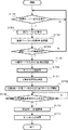
図4は、実施形態1に係るMFP100、PC110、中継サーバ120、管理サーバ130との間の通信を説明するシーケンス図である。このシーケンス図で示す動作は、MFP100のCPU211がHDD214からRAM213に展開したプログラムを実行することによって実現される。またPC110及び中継サーバ120、管理サーバ130の処理は、各装置のCPU311がHDD314からRAM313に展開したプログラムを実行することによって実現される。
FIG. 4 is a sequence diagram illustrating communication among the
MFP100は、ユーザが操作部220を介して支援開始要求を入力するとS401で、認証要求を、MFPの識別子と共に管理サーバ130へ送信する。尚、この支援開始要求は、MHP100の操作部220に表示される支援開始のボタンをユーザが押すことにより実行しても良いし、ユーザが操作部220のハードボタンにより特定の操作を行うことにより実行しても良い。MFPの識別子は、MFP100を特定するための全世界でユニークな識別子で、例えばMFP100のシリアル番号である。
When the user inputs a support start request via the
管理サーバ130は、上述したようにMFP100とコールセンターとを関連付けるMFP情報テーブル131を有している。管理サーバ130は、受信したMFPの識別子に基づいて、MFP100が管理サーバ130が管理するMFPであるかをMFP情報テーブル131を参照して判定し、管理対象であればS402で、認証トークンをMFP100に送信する。後のS404で、中継サーバ120がMFP100からのこの認証トークン(認証情報)を検証することにより、中継サーバ120は、管理サーバ130が管理していないMFPからの接続要求を拒否できる。また管理サーバ130はS403で、受信したMFPの識別子に基づいて、MFP情報テーブル131から中継サーバ120のURLを取得し、そのURLをMFP100に送信する。
The
次にS404でMFP100は、S403で受信した中継サーバ120のURLに対して、認証トークンの検証要求を発行する。これにより中継サーバ120は、その検証の結果として、S405でセッションIDをMFP100に返す。このセッションIDは、中継サーバ120へのログインが成功したことを証明するデータであり、中継サーバ120への支援URLの作成要求などの際に渡すデータである。このようにしてMFP100は、管理サーバ130から中継サーバ120への接続情報を受け取ることにより、適切な中継サーバ120への接続情報を取得することができる。こうして、この後、MFP100と中継サーバ120との間で、MFP100がPC110からの支援を受けるための支援URLと受付番号を作成するためのセッションが実行される。
Next, in S404, the
まずS406でMFP100は、中継サーバ120に支援URLの作成要求とセッションIDを送信する。これにより中継サーバ120は、S407で支援URLを作成すると共に、該支援URLと1対1に対応する受付番号を作成する。そしてS408で中継サーバ120は、その作成した支援URLをMFP100に送信する。そしてS409でMFP100は、その支援URLへ参加要求を送信する。こうしてMFP100は、中継サーバ120との通信が可能な状態となる。
First, in step S406, the
中継サーバ120は、MFP100から支援URLへの参加要求を受信すると、MFP100の情報を、参加者としてRAM313にバッファリングする。後述するように、中継サーバ120は、MFP100やPC110から支援URLへの参加者情報のGET要求を受信すると、RAM313にバッファリングされた参加者の更新情報を、MFP100やPC110に返す。また中継サーバ120は、MFP100やPC110から支援URLへの脱退要求を受信すると、RAM313にバッファリングされた参加者情報から該当情報を削除する。
次にS410で中継サーバ120は、S407で作成した受付番号をMFP100に送信する。尚、この受付番号は、中継サーバ120がMFP100から遠隔操作を支援するための要求を受付けたことに応じて作成する。受け付け番号は、中継サーバ120が受付を承認したことを示す受付情報であり、数字だけでなく文字を含んでも良い。また、S410で発行した受付番号は、中継サーバ120が作成する支援URLと1対1の対応関係にあるため、中継サーバ120は、作成した支援URLと受付番号とを関連付けてRAM313に保存する。よって、この受付番号から支援URLを取得することが可能になる。
Next, in S410,
次にS411でMFP100は、中継サーバ120から渡された受付番号を操作部220に表示する。そしてS412でMFP100は、支援URLへ参加者情報のGET要求を定期的に送信する。
Next, in step S411, the
一方、コールセンターのPC110はS413以降の処理で、管理サーバ130から認証トークンを取得し、それに基づいて中継サーバ120から支援URLを得て、MFP100との間で支援データのやり取りを行う。以下詳しく説明する。
On the other hand, the
S413でPC110は、中継サーバ120に接続するために、管理サーバ130にユーザ名とパスワードを送信して認証要求を行う。これによりS414で管理サーバ130は、PC110のユーザが管理サーバ130のオペレータ情報テーブル132に登録されているか否かを判定し、パスワードの検証を行い、正しければ認証トークンをPC110に送信する。こうして認証トークンを取得したPC110はS415で、中継サーバ120に認証トークンの検証要求を行う。これによりS416で中継サーバ120は、その検証の結果としてセッションIDをPC110に返す。次にPC110はS417で、中継サーバ120に支援URLの取得要求とセッションIDを送信する。このときPC110のオペレータは、中継サーバ120のURLは知っているが、S412によって作成された支援URLは知らない。従ってこれを特定するために、PC110のオペレータは、S411でMFP100の操作部220に表示された受付番号を、MFP100のユーザから取得してPC110に入力する。そしてS411でPC110は入力された受け付け番号をS418で中継サーバ120に送信する。尚、MFP100の操作部220に表示された受付番号をPC110のオペレータに伝えるのは、電話でも良いし、マイク223とスピーカ224を用いたIP電話や電子メールでも良い。これにより中継サーバ120は、RAM313に保存された受付番号の中から、S418で入力された受付番号と一致するものを求め、S419で、その受付番号に対応する支援URLを、PC110に送信する。こうしてS420でPC110は、中継サーバ120へ支援参加要求を発行する。中継サーバ120は、該要求を受信すると、PC110の情報を参加者としてRAM313にバッファリングする。これによりMFP100とPC110との間での支援データのやり取りができるようになる。
In step S413, the
S421で中継サーバ120は、S412で送信開始されたMFP100からのGET要求に対する応答として、参加者情報をMFP100へ送信する。これにより、MFP100は、自身を支援する装置としてPC110が選択されたことを把握することができる。こうしてS422,S423で、MFP100とPC110は、割り当てられた支援URLに対して、POST要求、GET要求を定期的に送信することにより、中継サーバ120を介した支援データの通信を行う。ここで支援データとしては、例えば、動画や音声、遠隔操作の命令データ、MFP100の持つデータなどが挙げられる。尚、MFP100の持つデータは、カウンタ値、稼動ログ、MFP100で使用されている各部品の消耗度を表す部品カウンタ値などの稼動情報、及びハード障害やジャム等の障害情報などを含む。例えば、MFP100にてジャムエラー等の障害が発生し、ユーザが障害復旧できない場合、その原因を探るため、障害情報をMFP100からコールセンター112のオペレータに通知するものとする。この場合、MFP100は障害を示す情報を支援URLにPOSTすると、中継サーバ120は当該情報をRAM313に格納する。その後、コールセンター112のPC110が支援URLに対してGET要求を送信すると、中継サーバ120はRAM313に格納された当該情報を応答としてPC110に送信する。続いてMFP100から送信された情報に基づいて障害の原因を把握したコールセンター112のオペレータがMFP100のユーザに対してエラーの解除方法を動画で伝えるものとする。この場合、コールセンター112のオペレータは、PC110を操作することにより、支援URLに対して動画データのPOST要求を送信すると、中継サーバ120は当該動画データをRAM313に格納する。その後MFP100が支援URLに対してGET要求を送信すると、中継サーバ120のRAM313に格納された動画データがMFP100に送信される。
In S421,
そして、MFP100のユーザによる作業が終了すると、S424でMFP100から支援URL(中継サーバ120)へ脱退要求を送信する。またPC110のオペレータによるMFP100への支援が終了したためS425でPC110は、支援URL(中継サーバ120)へ脱退要求を送信する。これにより中継サーバ120はS426で、不要になった支援URLと受付番号を破棄して、この処理を終了する。
When the operation of the user of
尚、ここではMFP100が先に中継サーバ120に接続し、その後、PC110が中継サーバ120に接続する例で説明したが、先にPC110が中継サーバ120へ接続し、その後、MFP100が中継サーバ120に接続しても良い。
Note that, here, an example in which the
図5は、実施形態1に係るMFP100により実行される処理を説明するフローチャートである。尚、このフローチャートで示す各動作(ステップ)は、MFP100のCPU211がHDD214に記憶されたプログラムをRAM213に展開して実行することによって実現される。
FIG. 5 is a flowchart illustrating processing executed by
先ずS501でCPU211は、MFP100の操作部220の特定のハードキーが長押しされて、遠隔保守サービスの開始が指示されたことを検知する。尚、実施形態1では、操作部220のハードキーの長押しを遠隔保守サービス開始のトリガとしているが、操作部220に表示されるボタンの押下や、操作部220の専用ハードキーの押下としても良い。また或いは、操作部220のハードキーを操作する特定の手順等をトリガとしても良い。S501でCPU211は、操作部220のハードキーの長押しを検知するとS502に進みCPU211は、遠隔保守サービスを開始するために、中継サーバ120に接続して良いかを確認するための画面を操作部220に表示する。尚、この画面は、MFP100が初めて遠隔保守サービスを利用するときに1度だけ表示しても良いし、毎回、表示しても良い。また、MFP100の設定により非表示に変更可能としても良い。
First, in step S501, the
次にS503に進みCPU211は、S502で操作部220に表示された画面の同意ボタンの押下を検知するとS504に進むが、同意でない場合はこの処理を終了する。S504でCPU211は、管理サーバ130に対して認証要求とMFPの識別子を送信して認証要求を発行し、その結果として認証に成功したかどうか判定する。ここで認証に失敗した場合は、処理を終了するが、認証に成功した場合はS505に進みCPU211は、管理サーバ130から認証トークンと中継サーバ120のURLを受信する。
Next, the process proceeds to step S503, and when the
次にS506に進みCPU211は、S505で受信した中継サーバ120のURLを用いて、S505で受信した認証トークンの検証要求を中継サーバ120に発行する。そしてS506で検証結果が正しい認証トークンであった場合はS507に進んで、CPU211は、中継サーバ120からセッションIDを受信する。次にS508に進みCPU211は、その受信したセッションIDをRAM213に保存してS509に進む。一方、S506で検証の結果、正しい認証トークンでなかった場合はS501に戻るか、或いはこの処理を終了する。
Next, the processing proceeds to step S506, and the
S509でCPU211は、支援URLの作成要求と、RAM213に保存されたセッションIDとを中継サーバ120に送信する。これにより中継サーバ120は、支援URLと受付番号を作成してMFP100に送信する。そしてS510でCPU211は、中継サーバ120から支援URLを受信するとS511に進み、CPU211は、その支援URL(中継サーバ120)へ参加要求を発行してS512に進む。S512でCPU211は、中継サーバ120から受付番号を受信するとS513に進み、CPU211は、その受信した受付番号を操作部220に表示する。この受付番号は、PC110が中継サーバ120の支援URLを特定するために、PC110で入力される。従って、この表示された受付番号は、上述したように電話やメールなどでPC110のオペレータに伝えられる。
In step S509, the
次にS514に進みCPU211は、支援URLに対する参加者情報のGET要求の定期的な送信を開始する。そしてS515でCPU211は、中継サーバ120から参加者情報を受信する。次にS516に進みCPU211は、中継サーバ120を介した支援データの送受信を開始する(S513)。具体的には、上述のように、支援URLへの支援データのPOST要求及びGET要求を送信することにより、PC110から送信される支援データを受信したり、PC110へ支援データを送信したりする。これによりMFP100のユーザは、PC110のオペレータから、音声や動画通信、遠隔操作による支援を受けることが可能となる。
Next, the processing proceeds to step S514, and the
こうしてPC110による支援が終了するとS517でCPU211は、操作部220から支援停止要求の入力を受け付けるのを待つ。CPU211は、操作部220から支援停止要求の入力を受けるとS518に進み、支援URLへ脱退要求を送信してS519に進む。S519でCPU211は、RAM213に保存されたセッションIDを破棄して、この処理を終了する。
When the support by the
図6は、実施形態1に係るPC110により実行される処理を説明するフローチャートである。尚、このフローチャートで示す各動作(ステップ)は、PC110のCPU311がHDD314に記憶されたプログラムをRAM313に展開して実行することによって実現される。
FIG. 6 is a flowchart illustrating processing executed by the
まずS601でCPU311は、管理サーバ130へ認証要求を発行する。このとき、操作部317を介して入力されたユーザ名とパスワードを管理サーバ130へ送信する。S601で認証に失敗した場合はS601に戻るか、或いはこの処理を終了する。S601で認証に成功した場合はS602に進みCPU311は、管理サーバ130から認証トークンを受信する。次にS603に進みCPU311は、S602で受信した認証トークンの検証要求を中継サーバ120に対して発行する。管理サーバ130での検証の結果、正しい認証トークンであった場合はS604に進みCPU311は、中継サーバ120からセッションIDを受信するとS605に進み、CPU311は、その受信したセッションIDをRAM313に保存する。
First, in S601, the
次にS606に進みCPU311は、支援URLの取得要求とセッションIDを中継サーバ120に送信する。そしてS607に進みCPU311は、オペレータにより操作部317から入力された受付番号を中継サーバ120に送信する。尚、ここで入力される受付番号は、前述したように、図5のS513でMFP100の操作部220に表示された受付番号である。この受付番号は、中継サーバ120が、既に接続済みのMFP100を特定し、中継サーバ120の支援URLを選択するために用いられ、前述したようにMFP100のユーザによって、電話或いはメール等によりPC110のオペレータに伝えられる。
Next, the process proceeds to S606, in which the
次にS608に進みCPU311は、中継サーバ120から支援URLを受信するとS609に進み、CPU311は、支援参加要求を中継サーバ120に送信する。そしてS610でCPU311は、中継サーバ120を介した支援データの送受信を開始する。具体的には、上述のように、支援URLへの支援データのPOST要求及びGET要求を送信することにより、MFP100から送信される支援データを受信したり、MFP100へ支援データを送信したりする。これによりPC110とMFP100との間での支援データのやり取りが実行される。
Next, proceeding to S608, when the
そして、PC110からMFP100への支援が終了するとCPU311は、S611でPC110の操作部317から支援停止要求の入力を受け付けるのを待つ。支援停止要求を受け付けるとS612に進みCPU311は、支援URL(中継サーバ120)へ脱退要求を送信する。そしてS613に進みCPU311は、RAM313に保存されたセッションIDを破棄して、この処理を終了する。
When the support from the
図7は、実施形態1に係る中継サーバ120により実行される処理を説明するフローチャートである。尚、このフローチャートで示す各動作(ステップ)は、中継サーバ120のCPU311がHDD314に記憶されたプログラムをRAM313に展開して実行することによって実現される。
FIG. 7 is a flowchart illustrating a process executed by the
先ずS701でCPU311は、MFP100から認証トークンの検証要求を受信すると、その検証を行う。ここでの検証は、受信した認証トークンが、管理サーバ130が発行したものであるか否かを検証する。認証トークンの検証結果が正しかった場合はS702に進みCPU311は、MFP100へのセッションIDを作成し保存する。このセッションIDは、中継サーバ120へのログインが成功したことを証明するデータである。そしてS703に進みCPU311は、そのセッションIDをMFP100へ送信する。尚、S701で検証結果が正しくなかったときはS701に進む。
First, in step S701, when the
次にS704でCPU311は、MFP100から支援URLの作成要求とセッションIDを受信するとS705に進む。S705でCPU311は、その受信したセッションIDがRAM313に保存したセッションIDと一致するか否かを判定し、一致するときは支援URLを作成する。次にS706に進みCPU311は、支援URLと1対1で対応する受付番号を生成してS707に進み、CPU311は、作成した支援URLと受付番号とを関連付けてRAM313に保存する(図4のS407に対応)。このRAM313に保存された受付番号を参照することによって、受付番号に対応する支援URLを取得することができる。尚、本実施形態では、受付番号は数字でも良いし、文字でも良い。また誤操作によって誤った受付番号が入力された場合のリスクを減らすために、ランダムな数字を受付番号としてもよい。
Next, in step S704, when the
次にS708に進みCPU311は、その支援URLをMFP100に送信してS709に進みCPU311は、MFP100から支援URLへの参加要求を受信する。次にS710に進みCPU311は、S706で作成した受付番号をMFP100へ送信する。これにより、その受付番号がMFP100の操作部220に表示される。次にS711に進みCPU311は、MFP100から参加者情報のGET要求を受信するとS712に進む。
Next, proceeding to S708, the
S712でCPU311は、PC110から認証トークンの検証要求を受信するとその検証を行う。ここでPC110からの認証トークンの検証に成功した場合はS713に進みCPU311は、セッションIDを生成してRAM313に保存する。ここでのセッションIDは、S702で生成されるセッションIDとは異なる値であり、それぞれ中継サーバ120のRAM313に保存される。次にS714に進みCPU311は、PC110へセッションIDを送信する。そしてS715に進みCPU311は、PC110からURLの取得要求とセッションIDを受信するとS716に進む。S716でCPU311は、S715で受信したセッションIDが、S713で中継サーバ120のRAM313に保存したセッションIDと同一であるか否かを判定し、そうであればCPU311は、そのPC110から受付番号を受信する。次にS717に進みCPU311は、S716で受信した受付番号を用いて、RAM313に保存された受付番号と支援URLのペアから支援URLを取得する。そしてS718に進みCPU311は、その取得した支援URLをPC110へ送信する。そしてS719に進みCPU311は、PC110から支援参加要求を受信する。
Upon receiving the authentication token verification request from the
次にS720に進みCPU311は、S711で受信したGET要求に対する応答としてMFP100に参加者情報を送信する。これにより、MFP100とPC110間で中継サーバ120を介した支援データの送受信が可能となる。S721でCPU311はMFP100又はPC110から支援データのPOST要求を受信すると、S722で当該支援データをRAM313に格納する。また、S723でMFP100又はPC110から支援データのGET要求を受信すると、S724でRAM313に格納されていた支援データを要求元に送信する。これにより、MFP100とPC110間で支援データが送受信され、PC110のオペレータは、MFP100のユーザに対する支援を行うことができる。
Next, proceeding to S720, the
そしてPC110のオペレータによる支援が終了するとS725に進みCPU311は、MFP100とPC110から、支援URLへ脱退要求が送信されてそれを受信するのを待つ。そして脱退要求を受信するとS726に進みCPU311は、RAM313に保存された支援URLと受付番号とセッションIDを破棄して、この処理を終了する。
When the support by the operator of the
図8は、実施形態1に係る管理サーバ130により実行される処理を説明するフローチャートである。尚、このフローチャートで示す各動作(ステップ)は、管理サーバ130のCPU311がHDD314に記憶されたプログラムをRAM313に展開して実行することによって実現される。
FIG. 8 is a flowchart illustrating processing executed by the
まずS801でCPU311は、MFP100から認証要求とMFPの識別子を受信するのを待つ。ここでMFPの識別子は、例えばMFP100の持つシリアル番号など、それぞれのMFPを識別可能な値である。そしてCPU311は、認証要求とMFPの識別子を受信するとS802に進み、受信したMFPの識別子が管理サーバ130のMFP情報テーブル131に含まれているか否か判定する。ここで含まれていない場合は、そのMFPは管理対象外であるため認証失敗として、この処理を終了する。一方、受信したMFPの識別子がMFP情報テーブル131に含まれていた場合はS803に進みCPU311は、そのMFPの識別子を持つMFP100が、どの中継サーバ120に接続するかをMFP情報テーブル131から取得する。次にS804に進みCPU311は、認証結果として認証トークンと、S803で取得した中継サーバのURLをMFP100へ送信する。これによりMFP100は、接続するべき適切な中継サーバ120のURLを取得できる。
First, in step S801, the
次にS805に進みCPU311は、PC110から認証要求とユーザ識別子を受信するのを待つ。ユーザ識別子とは、例えばユーザ名とパスワードなどの、それぞれのユーザを識別可能な値である。S805でCPU311は、認証要求とユーザ識別子を受信するとS806に進み、その受信したユーザ識別子が管理サーバ130のオペレータ情報テーブル132に含まれているかどうか判定する。ここで含まれていないと判定したときは、認証失敗として、この処理を終了する。一方、そのユーザ識別子がオペレータ情報テーブル132に含まれている場合はS807に進みCPU311は、認証結果として認証トークンをPC110へ送信して、この処理を終了する。
Next, the processing proceeds to step S805, and the
図9は、実施形態1に係る管理サーバ130のHDD314に記憶されているMFP情報テーブル131のデータ構成例を示す図である。ここではMFP1台分の情報を記述しているが、実際には複数台のMFPの情報が記憶されている。
FIG. 9 is a diagram illustrating a data configuration example of the MFP information table 131 stored in the
MFPID910は、MFPを識別するための識別情報である。MFPID910は、前述のMFPの識別子に該当する。管理サーバ130は、認証要求を送信してきたMFP100の識別子とMFPID910とを比較し、認証要求を送信してきたMFP100が管理サーバ130によって管理されているMFPであることを確認すると、認証トークンを発行することができる。名称911は、MFPの製品名称を示す。通報ID912は、MFP100の過去の通報を識別するための情報である。この通報ID912は、通報の数に応じて複数あってもよい。通報日時913は、通報の日時を示す。内容914は、その通報の内容を示す情報である。ステータス915は、その通報のステータスを示す情報である。
The
顧客ID920は、MFP100の顧客を識別するための識別情報である。名称921は、その顧客の名称を示す。
コールセンターID930は、MFP100を管理する販売組織のコールセンタ(所属先)を識別する識別情報である。名称931は、そのコールセンターの名称を示す。メールアドレス932は、そのコールセンターのメールアドレスを示す。
The
中継サーバURL940は、例えば図4のS403で、管理サーバ130からMFP100へ送信される中継サーバ120のURLである。この中継サーバURL940は、コールセンターID930に合わせて、MFP情報テーブル131に記録された複数台のMFPに一括で設定することもできるし、個別に設定することもできる。一般的に、コールセンターは、MFPの販売組織毎に運営される。よって、中継サーバ120においても、中継サーバ120の負荷軽減やセキュリティのために販売組織ごとに用意される。こうしたことから、コールセンターID930に基づいて中継サーバID940を一括で設定することにより、個別に設定するよりも、効率よく中継サーバID940を設定できる。
The
図10は、実施形態1に係る管理サーバ130のHDD314に記憶されているオペレータ情報テーブル132のデータ構成例を示す図である。ここではオペレータ1人の情報を載せているが、実際には複数人の情報が記憶されている。
FIG. 10 is a diagram illustrating a data configuration example of the operator information table 132 stored in the
オペレータID1010は、前述の図4のS413でPC110から管理サーバ130に送信されるユーザ名に該当するオペレータを識別するための識別情報である。パスワード1011は、前述のS413でPC110から管理サーバ130に送信されるパスワードに該当する情報、或いは、例えばパスワードを基にしたハッシュ値など、パスワードから一意に求めることのできる情報である。氏名1012はオペレータの氏名である。メールアドレス1013は、そのオペレータのメールアドレスである。電話番号1014は、そのオペレータの電話番号である。
The
コールセンターID930は、前述のコールセンタ(PCの所属先)を識別するための識別情報であり、オペレータID1010で示すオペレータが、どこのコールセンターに所属しているかを示す。名称931は、そのコールセンターの名称を示す情報、メールアドレス932は、そのコールセンターのメールアドレスを示す。
The
以上説明したように実施形態1によれば、管理サーバは、MFPからの支援開始要求に応じて、認証トークンと共に、接続先の中継サーバのURLを、そのMFPに送信する。これにより、MFPは適切な中継サーバに接続でき、その中継サーバを介して、MFPと支援するPCとが通信できるようになる。また管理サーバは、PCからの認証要求に応じて認証トークンを返すとPCは、その認証トークンを中継サーバで検証し、検証に成功すると支援URLを中継サーバから取得する。これにより、MFPとPCは適切な中継サーバを介して相互に通信でき、PCのオペレータがMFPのユーザを支援することがきるようになる。こうしてMFPとPCが、ファイアウォールでインターネットとの通信が保護されている環境でも、MFPがPCから遠隔保守サービスを受けることができる。 As described above, according to the first embodiment, the management server transmits the URL of the connection destination relay server to the MFP in response to the support start request from the MFP, together with the authentication token. Thereby, the MFP can be connected to an appropriate relay server, and the MFP and the supporting PC can communicate with each other via the relay server. When the management server returns the authentication token in response to the authentication request from the PC, the PC verifies the authentication token with the relay server, and if the verification is successful, acquires the support URL from the relay server. Thus, the MFP and the PC can communicate with each other via the appropriate relay server, and the PC operator can assist the MFP user. Thus, even in an environment where the MFP and the PC are protected from communication with the Internet by the firewall, the MFP can receive the remote maintenance service from the PC.
[実施形態2]
次に、本発明の実施形態2について説明する。前述の実施形態1では、PC110がMFP100の支援URLを特定する方法として、まず中継サーバ120が、作成した支援URLに対応した受付番号をMFPに送信し、MFPが操作部220にその受付番号を表示する。そしてMFPのユーザが、その受付番号をPC110のオペレータに伝えて、PC110から中継サーバ120へ、その受付番号を送信する。これにより中継サーバ120が、その支援URLを特定してPC110に通知するという方法を説明した。これに対して実施形態2では、受付番号ではなく、MFPの識別子を用いて支援URLを特定する例を説明する。尚、実施形態2に係るシステム構成、及びMFP,PC、中継サーバ、管理サーバのハードウェア構成は前述の実施形態1と同様であるため、その説明を省略する。
[Embodiment 2]
Next, a second embodiment of the present invention will be described. In the first embodiment, as a method in which the
コールセンターでは、遠隔保守サービスを開始する前に、顧客のユーザ情報や、対象のMFP100に関する情報を口頭で聞く場合がある。この場合、コールセンターのオペレータは、接続されるMFP100の識別子を知っている状態で遠隔保守サービスを開始することになる。ここでMFPの識別子を直接聞いても良いし、聞き出した情報を基に、管理サーバ130のMFP情報テーブル131を用いてMFPの識別子を特定することもできる。このMFPの識別子を用いて、中継サーバ120が支援URLを取得する方法について説明する。
Before starting the remote maintenance service, the call center may verbally hear customer user information or information about the
図11は、実施形態2に係るMFP100,PC110、中継サーバ120、管理サーバ130との間の通信を説明するシーケンス図である。このシーケンス図で示す動作は、MFP100のCPU211がHDD214からRAM213に展開したプログラムを実行することによって実現される。またPC110及び中継サーバ120、管理サーバ130の処理は、各装置のCPU311がHDD314からRAM313に展開したプログラムを実行することによって実現される。尚、この図11は、前述の実施形態の図4とほぼ同様であるため、異なる部分のみを説明する。
FIG. 11 is a sequence diagram illustrating communication among
S1101〜S1106は、実施形態1の図4のS401〜S406と同様であるため、その説明を省略する。ここではMFP100は管理サーバ130から中継サーバ120のURLを取得し、更にMFP100は、中継サーバ120に対して、支援URLの作成要求とセッションIDを送信する。
Steps S1101 to S1106 are the same as steps S401 to S406 in FIG. 4 of the first embodiment, and a description thereof will not be repeated. Here,
次にS1107でMFP100は、中継サーバ120にMFPの識別子を送信する。これにより中継サーバ120はS1108で、支援URLを作成する。前述の実施形態1のS407では、ここで受付番号も同時に生成し、支援URLと受付番号をペアとしてRAM213に保存したが、実施形態2では受付番号を作成せず、支援URLとMFPの識別子とを対応付けてRAM213に保存する。次のS1109,S1110,S1111では、図4のS408,S409,S412と同様に、MFP100は支援URLへの参加を要求し、中継サーバ120との間での通信を開始する。
Next, in S1107,
またS1112〜S1116は、図4のS413〜S417と同様に、PC110は管理サーバ130から認証トークンを取得し、それを基に中継サーバ120に対して支援URLの作成要求とセッションIDを送信する。
In steps S1112 to S1116, the
次にS1117でPC110は、中継サーバ120に、MFP100の識別子を送信する。これにより中継サーバ120は、S1117で受信したMFPの識別子と、RAM213に保存されたMFPの識別子とを比較し、それに対応する支援URLを取得して、S1118でPC110に送信する。これによりPC110は中継サーバ120を介した遠隔保守サービスを開始することができるようになる。
Next, in step S1117, the
そしてS1119〜S1124は、実施形態1の図4のS420〜S425と同様であるため、その説明を省略する。そして最後に中継サーバ120は、MFP100とPC110から支援URLへ脱退要求を受信するとS1125で中継サーバは、RAM213に保存された支援URLとMFPの識別子とを破棄して、この処理を終了する。
Steps S1119 to S1124 are the same as steps S420 to S425 in FIG. 4 of the first embodiment, and a description thereof will not be repeated. Then, finally, when the
これにより、コールセンターのPC110のオペレータは、遠隔保守サービスの対象であるMFP100の識別子を知っている状態で、遠隔保守サービスを開始することができるようになる。
Thus, the operator of the
図12は、実施形態2に係るMFP100により実行される処理を説明するフローチャートである。尚、このフローチャートで示す各動作(ステップ)は、MFP100のCPU211がHDD214に記憶されたプログラムをRAM213に展開して実行することによって実現される。尚、図12のフローチャートは、前述の実施形態1の図5とほぼ同様なため、異なる部分のみを以下、説明する。
FIG. 12 is a flowchart illustrating processing executed by
S1201〜S1209までは、図5のS501〜S509と同様であるため、その説明を省略する。 Steps S1201 to S1209 are the same as steps S501 to S509 in FIG. 5, and a description thereof will be omitted.
S1210でCPU211は、中継サーバ120へMFPの識別子を送信する。そしてS1211〜S1212は、図5のS510〜S511と同様であるため、その説明を省略する。またS1213〜S1218は、図5のS514〜S519と同様であるため、その説明を省略する。
In step S1210, the
ここではMFP100は、S1211で支援URLを受信する前に、中継サーバ120にMFP100の識別子を送信している。これにより中継サーバ120は、そのMFP100の識別子と支援URLとを関連付けて保存する。またこの実施形態2では、実施形態1で使用した受付番号を使用しないので、図5のS512,S513のように、受付番号を受信して表示する処理を省略できる。
Here, the
図13は、実施形態2に係るPC110により実行される処理を説明するフローチャートである。尚、このフローチャートで示す各動作(ステップ)は、PC110のCPU311がHDD314に記憶されたプログラムをRAM313に展開して実行することによって実現される。尚、このフローチャートは、前述の実施形態1の図6とほぼ同様なため、異なる部分のみを以下、説明する。S1301〜S1306は、図6のS601〜S606と同様であるため、その説明を省略する。
FIG. 13 is a flowchart illustrating processing executed by the
S1307でCPU311は、MFPの識別子を中継サーバ120へ送信する。尚、S1307で送信するMFP100の識別子は、前述したように、遠隔操作支援の開始前に顧客の情報から取得済みのものである。そしてS1308〜S1313は、図6のS608〜S613と同様であるため、その説明を省略する。
In S1307, the
図14は、実施形態2に係る中継サーバ120により実行される処理を説明するフローチャートである。尚、このフローチャートで示す各動作(ステップ)は、中継サーバ120のCPU311がHDD314に記憶されたプログラムをRAM313に展開して実行することによって実現される。尚、このフローチャートは、前述の実施形態1の図7とほぼ同様であるため、異なる部分のみを以下、説明する。S1401〜S1404は、図7のS701〜S704と同様であるため、その説明を省略する。
FIG. 14 is a flowchart illustrating a process executed by the
S1405でCPU311は、MFP100からMFPの識別子を受信するとS1406に進みCPU311は、S1404で受信したセッションIDを確認し、支援URLを作成する。そしてS1407に進みCPU311は、支援URLとMFPの識別子とをペアとしてRAM313に保存する。このRAM313に保存されたMFPの識別子を参照することによって、MFPの識別子から支援URLを取得することができる。S1408〜S1409は、図7のS708〜S709と同様であるため、その説明を省略する。またS1410〜S1414は、図7のS711〜S715と同様であるため、その説明を省略する。
Upon receiving the MFP identifier from the
そしてS1415でCPU311は、PC110からMFPの識別子を受信するとS1416に進み、CPU311は、その受信したMFPの識別子を用いて、RAM313に保存されたMFPの識別子と支援URLのペアから、支援URLを取得する。そしてS1417〜S1424は、図7のS718〜S725と同様であるため、その説明を省略する。そして最後にPC110のオペレータによる支援が終了すると、S1425でCPU311は、RAM313に保存された支援URLとMFPの識別子とセッションIDを破棄して、この処理を終了する。
When the
尚、実施形態2に係る管理サーバ130により実行される処理の説明は、前述の実施形態1に係る図8のフローチャートと同じであるため、その説明を省略する。
Note that the description of the processing executed by the
以上説明したように実施形態2によれば、MFPからの支援開始要求に応じて、管理サーバが認証トークンと共に、接続先の中継サーバのURLをMFPに送信する。これによりMFPは適切な中継サーバに接続でき、その中継サーバを介してMFPとPCとが通信可能となり、MFPはPCから遠隔保守サービスを受けることができる。 As described above, according to the second embodiment, in response to the support start request from the MFP, the management server transmits the URL of the connection destination relay server to the MFP together with the authentication token. As a result, the MFP can be connected to an appropriate relay server, the MFP and the PC can communicate with each other via the relay server, and the MFP can receive a remote maintenance service from the PC.
[実施形態3]
次に、本発明の実施形態3について説明する。前述の実施形態1では、PCがMFPの支援URLを特定するために、中継サーバが作成した支援URLに対応した受付番号を作成し、その受付番号により中継サーバがPCとMFPとを特定する例で説明した。また実施形態2では、受付番号ではなく、MFPの識別子を用いてPCに支援URLを伝える例を説明した。これに対して実施形態3では、MFPが管理サーバに支援URLとMFPの識別子を送信し、管理サーバがPCに支援URLを送信する例で説明する。尚、実施形態3に係るシステム構成、及びMFP,PC,中継サーバ、管理サーバのハードウェア構成は前述の実施形態1と同様であるため、その説明を省略する。
[Embodiment 3]
Next, a third embodiment of the present invention will be described. In the above-described first embodiment, an example in which the PC creates a reception number corresponding to the support URL created by the relay server in order to identify the support URL of the MFP, and the relay server identifies the PC and the MFP based on the reception number It was explained in. In the second embodiment, an example has been described in which the support URL is transmitted to the PC using the MFP identifier instead of the reception number. In contrast, in the third embodiment, an example will be described in which the MFP transmits the support URL and the identifier of the MFP to the management server, and the management server transmits the support URL to the PC. Note that the system configuration according to the third embodiment and the hardware configuration of the MFP, the PC, the relay server, and the management server are the same as those in the first embodiment, and a description thereof will be omitted.
図15は、実施形態3に係るMFP100、PC110、中継サーバ120、管理サーバ130との間の通信を説明するシーケンス図である。このシーケンス図で示す動作は、MFP100のCPU211がHDD214からRAM213に展開したプログラムを実行することによって実現される。またPC110及び中継サーバ120、管理サーバ130の処理は、CPU311がHDD314からRAM313に展開したプログラムを実行することによって実現される。尚、この図11は、前述の実施形態の図4とほぼ同様であるため、異なる部分のみを説明する。
FIG. 15 is a sequence diagram illustrating communication among
S1501〜S1506は、図4のS401〜S406と同様であるため、その説明を省略する。S1507で中継サーバ120は、支援URLを作成する。S1508〜S1509は、図4のS408〜S409と同様であるため、その説明を省略する。
Steps S1501 to S1506 are the same as steps S401 to S406 in FIG. 4, and thus description thereof is omitted. In S1507,
S1510でMFP100は、管理サーバ130にMFPの識別子と支援URLを送信する。そしてS1511〜S1513は、図4のS412〜S414と同様であるため、その説明を省略する。そしてS1514で管理サーバ130は、PC110へ支援URLを送信する。ここでの送信手段としては、管理サーバ130がMFPの識別子を用いてMFP情報テーブル131から取得できるコールセンタメールアドレス932を宛先とした電子メールによって送信する。そしてS1515〜S1516は、図4のS415〜S416と同様であるため、その説明を省略する。またS1517〜S1522は、図4のS420〜S425と同様であるため、その説明を省略する。そして最後にPC110のオペレータによる支援が終了すると、中継サーバ120は支援URLを破棄して、この処理を終了する。
In step S1510, the
図16は、実施形態3に係るMFP100により実行される処理を説明するフローチャートである。尚、このフローチャートで示す各動作(ステップ)は、MFP100のCPU211がHDD214に記憶されたプログラムをRAM213に展開して実行することによって実現される。尚、この図5のフローチャートは、前述の実施形態1の図5のフローチャートとほぼ同様であるため、異なる部分のみを以下、説明する。S1601〜S1611は、図5のS501〜S511と同様であるため、その説明を省略する。
FIG. 16 is a flowchart illustrating processing executed by
S1612でCPU211は、管理サーバ130へMFP100の識別子と、S1610で受信した支援URLとを送信する。そしてS1613〜S1618は、図5のS514〜S519と同様であるため、その説明を省略する。
In S1612, the
図17は、実施形態3に係るPC110により実行される処理を説明するフローチャートである。尚、このフローチャートで示す各動作(ステップ)は、PC110のCPU311がHDD314に記憶されたプログラムをRAM313に展開して実行することによって実現される。尚、このフローチャートは、前述の実施形態1の図6のフローチャートとほぼ同様であるため、異なる部分のみを以下その説明を省略する。S1701〜S1702は、図6のS601〜S602と同様であるため、その説明を省略する。
FIG. 17 is a flowchart illustrating processing executed by the
S1703でCPU311は、管理サーバ130から支援URLを受信する。ここでの支援URLの受信方法は、管理サーバ130から送信された電子メールである。そしてS1704〜S1706は、図6のS603〜S605と同様であるため、その説明を省略する。そしてS1707でCPU311は、S1703で受信した支援URLを用いて、支援参加要求を中継サーバ120へ送信する。そしてS1708〜S1711は、図6のS610〜S613の処理と同様であるため、その説明を省略する。
In step S1703, the
図18は、実施形態3に係る中継サーバ120により実行される処理を説明するフローチャートである。尚、このフローチャートで示す各動作(ステップ)は、中継サーバ120のCPU311がHDD314に記憶されたプログラムをRAM313に展開して実行することによって実現される。このフローチャートは、前述の実施形態1の図7のフローチャートとほぼ同様であるため、異なる部分のみを以下、説明する。図18において、S1801〜S1805は、図7のS701〜S705と同様であるため、その説明を省略する。
FIG. 18 is a flowchart illustrating a process executed by the
S1806でCPU311は、S1805で作成した支援URLをRAM313に保存する。S1807〜S1808は、図7のS708〜S709と同様であるため、その説明を省略する。更にS1809〜S1812は、図7のS711〜S714と同様であるため、その説明を省略する。更にS1813〜S1820は、図7のS719〜S726までと同様であるため、その説明を省略する。
In step S1806, the
図19は、実施形態3に係る管理サーバ130により実行される処理を説明するフローチャートである。尚、このフローチャートで示す各動作(ステップ)は、管理サーバ130のCPU311がHDD314に記憶されたプログラムをRAM313に展開して実行することによって実現される。このフローチャートは、前述の実施形態1の図8のフローチャートとほぼ同様なため、異なる部分のみを以下、説明する。図において、S1901〜S1904は、図8のS801〜S804と同様であるため、その説明を省略する。
FIG. 19 is a flowchart illustrating a process executed by the
S1905でCPU311は、MFP100から識別子と支援URLを受信する。S1906〜S1908は、図8のS805〜S807と同様であるため、その説明を省略する。そしてS1909に進みCPU311は、S1905で受信したMFPの識別子を用いて、MFP情報テーブル131からコールセンタメールアドレス932を取得する。次にS1910に進みCPU311は、S1909で取得したコールセンタメールアドレス932を宛先として、S1905で受信した支援URLを送信する。
In S1905, the
以上説明したように実施形態3によれば、MFP100からの支援開始要求に応じて、管理サーバ130が認証トークンと共に、接続先の中継サーバ120のURLをMFP100に送信する。これによりMFP100は、その中継サーバ120に接続し、その中継サーバ120へのアクセス情報を管理サーバ130を介してPC110に知らせることにより、中継サーバ120を介してPC110と通信可能となり、PC110から遠隔保守サービスを受けることができる。
According to the third embodiment As described above, according to the support start request from
(その他の実施形態)
本発明は、上述の実施形態の1以上の機能を実現するプログラムを、ネットワーク又は記憶媒体を介してシステム又は装置に供給し、そのシステム又は装置のコンピュータにおける1つ以上のプロセッサーがプログラムを読出し実行する処理でも実現可能である。また、1以上の機能を実現する回路(例えば、ASIC)によっても実現可能である。
(Other embodiments)
The present invention supplies a program for realizing one or more functions of the above-described embodiments to a system or an apparatus via a network or a storage medium, and one or more processors in a computer of the system or the apparatus read and execute the program. This processing can be realized. Further, it can also be realized by a circuit (for example, an ASIC) that realizes one or more functions.
本発明は上記実施形態に制限されるものではなく、本発明の精神及び範囲から離脱することなく、様々な変更及び変形が可能である。従って、本発明の範囲を公にするために、以下の請求項を添付する。 The present invention is not limited to the above embodiments, and various changes and modifications can be made without departing from the spirit and scope of the present invention. Therefore, to make the scope of the present invention public, the following claims are appended.
100…MFP,110…PC,120…中継サーバ、130…管理サーバ、111−1,111−2…ファイアウォール、211,311…CPU、131…MFP情報テーブル、132…オペレータ情報テーブル 100 MFP, 110 PC, 120 relay server, 130 management server, 111-1, 111-2 firewall, 211, 311 CPU, 131 MFP information table, 132 operator information table
Claims (17)
前記管理サーバは、
前記第1の端末からの認証要求に基づいて当該第1の端末を認証すると前記第1の端末に前記中継サーバに対して認証するための認証情報と前記中継サーバへの接続情報を通知する第1の通知手段と、
前記第2の端末からの認証要求に基づいて当該第2の端末を認証すると前記第2の端末に前記中継サーバに対して認証するための認証情報を通知する第2の通知手段と、
を有し、
前記中継サーバは、
前記第1の端末からの認証情報を含む要求に応じて、前記第1と第2の端末との間の通信に使用する中継サーバへのアクセス情報を作成して前記第1の端末に送信する第1の送信手段と、
前記第2の端末から認証情報を含む要求に応じて、前記アクセス情報を前記第2の端末に送信する第2の送信手段と、
前記アクセス情報に基づいて前記第1及び第2の端末との間で行われる通信を中継する中継手段と、
を有することを特徴とする通信システム。 Communication system including first and second terminals, a management server that manages the first and second terminals, and a relay server that relays communication between the first terminal and the second terminal And
The management server,
Authenticating the first terminal based on an authentication request from the first terminal, and notifying the first terminal of authentication information for authenticating to the relay server and connection information to the relay server. 1 notification means,
A second notifying unit for notifying the second terminal of authentication information for authenticating the relay server when authenticating the second terminal based on an authentication request from the second terminal;
Has,
The relay server,
In response to a request including authentication information from the first terminal, access information to a relay server used for communication between the first and second terminals is created and transmitted to the first terminal. First transmitting means;
Second transmission means for transmitting the access information to the second terminal in response to a request including authentication information from the second terminal;
Relay means for relaying communication performed between the first and second terminals based on the access information;
A communication system comprising:
前記第1の端末からの前記要求に応じて、当該要求を受付けたことを示す受付情報を作成して前記第1の送信手段により前記アクセス情報とともに前記第1の端末に送信し、
前記第2の端末からの前記認証情報と前記受付情報を含む要求に応じて、前記第2の送信手段により前記アクセス情報を前記第2の端末に送信することを特徴とする請求項1に記載の通信システム。 The relay server further includes:
In response to the request from the first terminal, create reception information indicating that the request has been received, and transmit the reception information to the first terminal together with the access information by the first transmission unit;
The method according to claim 1, wherein the access information is transmitted to the second terminal by the second transmission unit in response to a request including the authentication information and the reception information from the second terminal. Communication system.
前記第1の端末から、当該第1の端末の識別情報を含む要求に応じて、前記第1の送信手段により前記アクセス情報を前記第1の端末に送信し、
前記第2の端末からの前記認証情報と前記第1の端末の識別情報を含む要求に応じて、前記第2の送信手段により前記アクセス情報を前記第2の端末に送信することを特徴とする請求項1に記載の通信システム。 The relay server further includes:
Transmitting, from the first terminal, the access information to the first terminal by the first transmitting means in response to a request including identification information of the first terminal;
The access information is transmitted to the second terminal by the second transmission means in response to a request including the authentication information and the identification information of the first terminal from the second terminal. The communication system according to claim 1.
前記第2の端末は、前記表示手段に表示された前記受付情報をユーザを介して受け取ることを特徴とする請求項2に記載の通信システム。 The first terminal further includes display means for displaying the reception information received from the relay server in response to the request,
The communication system according to claim 2, wherein the second terminal receives the reception information displayed on the display unit via a user.
前記管理サーバは、
前記第1の端末からの認証要求に基づいて当該第1の端末を認証すると前記第1の端末に前記中継サーバに対して認証するための認証情報と前記中継サーバへの接続情報を通知する第1の通知手段と、
前記第1の端末が前記接続情報に基づいて前記中継サーバと接続して前記中継サーバから取得した前記中継サーバへのアクセス情報を、前記第1の端末から取得する取得手段と、
前記第2の端末からの認証要求に基づいて当該第2の端末を認証すると、前記第2の端末に、前記中継サーバに対して認証するための認証情報と、前記取得手段により取得した前記中継サーバへのアクセス情報とを通知する第2の通知手段と、
を有し、
前記中継サーバは、
前記第1の端末からの認証情報を含む要求に応じて、前記第1と第2の端末との間の通信に使用する中継サーバへの前記アクセス情報を作成して前記第1の端末に送信する第1の送信手段と、
前記アクセス情報に基づく前記第2の端末から認証情報を含む要求に応じて、前記第1及び第2の端末との間で行われる通信を中継する中継手段と、
を有することを特徴とする通信システム。 A communication system including first and second terminals, a management server that manages the first and second terminals, and a relay server that relays communication between the first terminal and the second terminal And
The management server,
Authenticating the first terminal based on an authentication request from the first terminal, and notifying the first terminal of authentication information for authenticating to the relay server and connection information to the relay server. 1 notification means,
Acquiring means for acquiring, from the first terminal, access information to the relay server, wherein the first terminal connects to the relay server based on the connection information and acquires from the relay server;
Upon authenticating the second terminal based on the authentication request from the second terminal, said second terminal, and authentication information for authenticating to the relay server, the relay acquired by the acquisition unit Second notification means for notifying access information to the server;
Has,
The relay server,
In response to a request that includes authentication information from said first terminal, transmitting to said first and said first terminal to create the access information to the relay server used for communication between the second terminal First transmitting means for performing
Relay means for relaying communication performed between the first and second terminals in response to a request including authentication information from the second terminal based on the access information;
A communication system comprising:
前記指示手段による指示に応じて、前記管理サーバに前記認証要求を送信することを特徴とする請求項1乃至6のいずれか1項に記載の通信システム。 The first terminal has an instruction unit that instructs start of communication performed between the first and second terminals,
The communication system according to claim 1, wherein the authentication request is transmitted to the management server in response to an instruction from the instruction unit.
前記第1の端末の識別情報、前記第1の端末が使用する前記中継サーバへの接続情報、及び前記第1の端末に関連する前記第2の端末の所属先の情報を記憶する第1の記憶手段と、
前記第2の端末の所属先のオペレータの識別情報を記憶する第2の記憶手段と、を有することを特徴とする請求項1乃至7のいずれか1項に記載の通信システム。 The management server,
A first terminal that stores identification information of the first terminal, connection information to the relay server used by the first terminal, and information of an affiliation of the second terminal related to the first terminal; Storage means;
The communication system according to any one of claims 1 to 7, further comprising: a second storage unit configured to store identification information of an operator to which the second terminal belongs.
前記遠隔操作支援の開始を指示する指示手段と、
前記指示手段による指示に応じて、管理サーバに認証要求を送信する第1の送信手段と、
前記認証要求に応答して前記管理サーバから送信される中継サーバへの接続情報を受信する受信手段と、
前記接続情報に基づいて前記中継サーバに対して、前記遠隔操作支援のための前記中継サーバへのアクセス情報の作成を要求する要求手段と、
前記要求手段による要求に応答して前記中継サーバから前記アクセス情報を取得すると、当該アクセス情報に基づいて前記中継サーバを介して前記情報処理装置との間で情報の送受信を行う通信手段と、
を有することを特徴とする画像形成装置。 An image forming apparatus capable of receiving remote operation support by an information processing apparatus via a relay server,
Instruction means for instructing the start of the remote operation support,
First transmission means for transmitting an authentication request to a management server in response to an instruction from the instruction means;
Receiving means for receiving connection information to the relay server transmitted from the management server in response to the authentication request;
Requesting means for requesting the relay server based on the connection information to create access information to the relay server for the remote operation support;
When acquiring the access information from the relay server in response to a request by the request unit, a communication unit that transmits and receives information to and from the information processing device via the relay server based on the access information;
An image forming apparatus comprising:
前記情報処理装置は、前記表示手段に表示された前記受付情報をユーザを介して受け取ることを特徴とする請求項10に記載の画像形成装置。 Along with the access information from the relay server in response to the request by the request unit, when receiving reception information indicating that the request has been received from the relay server, further comprising a display unit for displaying the reception information,
The image forming apparatus according to claim 10, wherein the information processing apparatus receives the reception information displayed on the display unit via a user.
前記情報処理装置は、前記管理サーバを介して前記アクセス情報を受け取ることを特徴とする請求項10に記載の画像形成装置。 When acquiring the access information from the relay server in response to the request by the request unit, the image processing apparatus further includes a second transmission unit that transmits the access information and identification information to the image forming apparatus to the management server,
The image forming apparatus according to claim 10, wherein the information processing apparatus receives the access information via the management server.
前記管理サーバにおいて、
第1の通知手段が、前記第1の端末からの認証要求に基づいて当該第1の端末を認証すると前記第1の端末に前記中継サーバに対して認証するための認証情報と前記中継サーバへの接続情報を通知する第1の通知工程と、
第2の通知手段が、前記第2の端末からの認証要求に基づいて当該第2の端末を認証すると前記第2の端末に前記中継サーバに対して認証するための認証情報を通知する第2の通知工程と、を実行し、
前記中継サーバにおいて、
第1の送信手段が、前記第1の端末からの認証情報を含む要求に応じて、前記第1と第2の端末との間の通信に使用する中継サーバへのアクセス情報を作成して前記第1の端末に送信する第1の送信工程と、
第2の送信手段が、前記第2の端末から認証情報を含む要求に応じて、前記アクセス情報を前記第2の端末に送信する第2の送信工程と、
中継手段が、前記アクセス情報に基づいて前記第1及び第2の端末との間で行われる通信を中継する中継工程と、
を有することを特徴とする通信システムの制御方法。 Communication system including first and second terminals, a management server that manages the first and second terminals, and a relay server that relays communication between the first terminal and the second terminal Control method,
In the management server,
When the first notifying unit authenticates the first terminal based on an authentication request from the first terminal, authentication information for authenticating the first terminal to the relay server and the authentication information to the relay server A first notification step of notifying the connection information of
A second notifying unit that, when authenticating the second terminal based on an authentication request from the second terminal, notifies the second terminal of authentication information for authenticating the relay server; And the notification process of
In the relay server,
In response to a request including authentication information from the first terminal, first transmission means creates access information to a relay server used for communication between the first and second terminals, and A first transmitting step of transmitting to the first terminal;
A second transmitting unit that transmits the access information to the second terminal in response to a request including authentication information from the second terminal;
A relay step of relaying communication performed between the first and second terminals based on the access information;
A control method for a communication system, comprising:
指示手段が、前記遠隔操作支援の開始を指示する指示工程と、
送信手段が、前記指示工程による指示に応じて、管理サーバに認証要求を送信する送信工程と、
受信手段が、前記認証要求に応答して前記管理サーバから送信される中継サーバへの接続情報を受信する受信工程と、
要求手段が、前記接続情報に基づいて前記中継サーバに対して、前記遠隔操作支援のための前記中継サーバへのアクセス情報の作成を要求する要求工程と、
通信手段が、前記要求工程による要求に応答して前記中継サーバから前記アクセス情報を取得すると、当該アクセス情報に基づいて前記中継サーバを介して前記情報処理装置との間で情報の送受信を行う通信工程と、
を有することを特徴とする画像形成装置の制御方法。 A method of controlling an image forming apparatus capable of receiving remote operation support by an information processing apparatus via a relay server,
Instruction means for instructing the start of the remote operation support,
Transmitting means for transmitting an authentication request to the management server in accordance with the instruction in the instruction step,
Receiving means for receiving connection information to the relay server transmitted from the management server in response to the authentication request,
Requesting means for requesting the relay server based on the connection information to request creation of access information to the relay server for the remote operation support;
When the communication means obtains the access information from the relay server in response to the request in the requesting step, communication for transmitting and receiving information to and from the information processing device via the relay server based on the access information. Process and
A method for controlling an image forming apparatus, comprising:
Priority Applications (4)
| Application Number | Priority Date | Filing Date | Title |
|---|---|---|---|
| JP2015180115A JP6655921B2 (en) | 2015-09-11 | 2015-09-11 | Communication system and control method thereof, image forming apparatus and control method thereof, and program |
| EP16185264.5A EP3142343B1 (en) | 2015-09-11 | 2016-08-23 | Communication system, image forming apparatus and method of controlling the same, and storage medium |
| US15/251,365 US10129427B2 (en) | 2015-09-11 | 2016-08-30 | System for establishing communication between a plurality of terminals, method of controlling the same, and storage medium |
| CN201610811484.7A CN106534604B (en) | 2015-09-11 | 2016-09-08 | Communication system and its control method, image forming apparatus and its control method |
Applications Claiming Priority (1)
| Application Number | Priority Date | Filing Date | Title |
|---|---|---|---|
| JP2015180115A JP6655921B2 (en) | 2015-09-11 | 2015-09-11 | Communication system and control method thereof, image forming apparatus and control method thereof, and program |
Publications (2)
| Publication Number | Publication Date |
|---|---|
| JP2017054458A JP2017054458A (en) | 2017-03-16 |
| JP6655921B2 true JP6655921B2 (en) | 2020-03-04 |
Family
ID=56883543
Family Applications (1)
| Application Number | Title | Priority Date | Filing Date |
|---|---|---|---|
| JP2015180115A Active JP6655921B2 (en) | 2015-09-11 | 2015-09-11 | Communication system and control method thereof, image forming apparatus and control method thereof, and program |
Country Status (4)
| Country | Link |
|---|---|
| US (1) | US10129427B2 (en) |
| EP (1) | EP3142343B1 (en) |
| JP (1) | JP6655921B2 (en) |
| CN (1) | CN106534604B (en) |
Families Citing this family (16)
| Publication number | Priority date | Publication date | Assignee | Title |
|---|---|---|---|---|
| JP6747223B2 (en) * | 2016-09-29 | 2020-08-26 | セイコーエプソン株式会社 | Server and server control method |
| JP2018093433A (en) * | 2016-12-06 | 2018-06-14 | キヤノン株式会社 | Communication system, image forming device and control method thereof, and program |
| JP6881055B2 (en) | 2017-06-14 | 2021-06-02 | 株式会社リコー | Information processing system, information processing method, information processing program, information processing device, data output device control program and data output device |
| JP6619775B2 (en) * | 2017-06-28 | 2019-12-11 | キヤノン株式会社 | COMMUNICATION DEVICE, SYSTEM, CONTROL METHOD, AND PROGRAM |
| JP6607361B2 (en) * | 2017-06-30 | 2019-11-20 | 京セラドキュメントソリューションズ株式会社 | Remote communication system |
| JP6751267B2 (en) * | 2017-06-30 | 2020-09-02 | 京セラドキュメントソリューションズ株式会社 | Remote communication control system, remote communication system, session management system and session management program |
| JP6777887B2 (en) * | 2017-06-30 | 2020-10-28 | 京セラドキュメントソリューションズ株式会社 | Remote communication control system, session management system and session management program |
| JP6751269B2 (en) * | 2017-06-30 | 2020-09-02 | 京セラドキュメントソリューションズ株式会社 | Remote communication control system, session management system and session management program |
| US10338864B2 (en) * | 2017-06-30 | 2019-07-02 | Kyocera Document Solutions Inc. | Remote communication system that improves security of remote session between image forming apparatus and connection terminal, and session management system |
| JP2019040359A (en) | 2017-08-24 | 2019-03-14 | キヤノン株式会社 | Communication system, relay server, information processing device and image formation device, and control method and program controlling the same |
| JP2019086851A (en) * | 2017-11-01 | 2019-06-06 | シャープ株式会社 | Information processing device and information processing system |
| JP7146431B2 (en) * | 2018-04-13 | 2022-10-04 | キヤノン株式会社 | System, information processing device, control method for information processing device, and program |
| JP6958481B2 (en) * | 2018-05-25 | 2021-11-02 | 京セラドキュメントソリューションズ株式会社 | Remote management system and information processing method |
| CN110635934A (en) * | 2018-06-22 | 2019-12-31 | 京瓷办公信息系统株式会社 | Remote management system and information processing method |
| JP6754105B2 (en) * | 2019-10-16 | 2020-09-09 | 京セラドキュメントソリューションズ株式会社 | Remote communication system |
| CN110809330B (en) * | 2019-12-16 | 2023-07-14 | 腾讯科技(深圳)有限公司 | Multi-terminal connection establishment method and device, storage medium and electronic device |
Family Cites Families (16)
| Publication number | Priority date | Publication date | Assignee | Title |
|---|---|---|---|---|
| US7480937B2 (en) * | 2002-02-26 | 2009-01-20 | Ricoh Company, Ltd. | Agent device, image-forming-device management system, image-forming-device management method, image-forming-device management program, and storage medium |
| US20060061803A1 (en) * | 2004-09-20 | 2006-03-23 | Kabushiki Kaisha Toshiba | Image forming system and communication method |
| EP1833222A1 (en) * | 2006-03-10 | 2007-09-12 | Abb Research Ltd. | Access control protocol for embedded devices |
| CN102238201B (en) * | 2010-04-23 | 2016-09-28 | 中兴通讯股份有限公司 | Internet of Things application module and Internet of Things apply the communication means with internet-of-things terminal |
| JP2011242992A (en) * | 2010-05-18 | 2011-12-01 | Canon Inc | Information processor, document management device, print outputting method and computer program |
| JP5724498B2 (en) * | 2011-03-18 | 2015-05-27 | 株式会社リコー | Allocation device, communication device, mediation device, mediation system, allocation method, program, and recording medium |
| JP5853464B2 (en) | 2011-07-27 | 2016-02-09 | キヤノンマーケティングジャパン株式会社 | Information processing apparatus, control method, and program |
| JP2014059720A (en) | 2012-09-18 | 2014-04-03 | Canon Inc | Remote support system, image forming apparatus, and information processing apparatus |
| KR101422808B1 (en) * | 2012-09-21 | 2014-08-14 | 주식회사 팬택 | Equipment and method for providing a service for sharing a drawing screen between mobile devices and mobile device for the same |
| KR101416541B1 (en) * | 2012-12-27 | 2014-07-09 | 주식회사 로웸 | Safety login system and the method and apparatus therefor |
| US9374369B2 (en) * | 2012-12-28 | 2016-06-21 | Lookout, Inc. | Multi-factor authentication and comprehensive login system for client-server networks |
| JP5867448B2 (en) * | 2013-04-26 | 2016-02-24 | コニカミノルタ株式会社 | Network system, access support server, processing device, communication proxy device, and computer program |
| JP6288988B2 (en) * | 2013-08-21 | 2018-03-07 | キヤノン株式会社 | Remote support device, electronic device, remote support method, and computer program |
| JP6344907B2 (en) * | 2013-11-29 | 2018-06-20 | キヤノン株式会社 | Information processing apparatus, system, and control method for information processing apparatus |
| JP6204821B2 (en) * | 2013-12-20 | 2017-09-27 | キヤノン株式会社 | Image forming apparatus, control method thereof, and program |
| JP6335607B2 (en) * | 2014-04-21 | 2018-05-30 | キヤノン株式会社 | Communication system, image processing apparatus, image processing apparatus control method, and program |
-
2015
- 2015-09-11 JP JP2015180115A patent/JP6655921B2/en active Active
-
2016
- 2016-08-23 EP EP16185264.5A patent/EP3142343B1/en active Active
- 2016-08-30 US US15/251,365 patent/US10129427B2/en active Active
- 2016-09-08 CN CN201610811484.7A patent/CN106534604B/en active Active
Also Published As
| Publication number | Publication date |
|---|---|
| EP3142343A1 (en) | 2017-03-15 |
| CN106534604B (en) | 2019-05-28 |
| CN106534604A (en) | 2017-03-22 |
| US10129427B2 (en) | 2018-11-13 |
| US20170078512A1 (en) | 2017-03-16 |
| EP3142343B1 (en) | 2020-11-18 |
| JP2017054458A (en) | 2017-03-16 |
Similar Documents
| Publication | Publication Date | Title |
|---|---|---|
| JP6655921B2 (en) | Communication system and control method thereof, image forming apparatus and control method thereof, and program | |
| JP6335607B2 (en) | Communication system, image processing apparatus, image processing apparatus control method, and program | |
| US10148852B2 (en) | Image processing system, control apparatus, image processing apparatus, and methods of controlling these | |
| US8976402B2 (en) | Method of controlling communication system | |
| US10554831B2 (en) | Remote maintenance system for image processing apparatus, capable of reducing user's time and effort, communication establishment method, and storage medium | |
| JP6278651B2 (en) | Network system, management server system, control method and program | |
| US9866407B2 (en) | Information processing system, cloud server, device control method, and non-transitory computer-readable recording medium encoded with device control program | |
| JP2017199088A (en) | Relay server, control method thereof, communication system, and program | |
| JP6343178B2 (en) | Communication system and control method therefor, first terminal and control method therefor, and program | |
| JP2019040359A (en) | Communication system, relay server, information processing device and image formation device, and control method and program controlling the same | |
| JP6368157B2 (en) | Communication system and control method thereof | |
| EP4068073B1 (en) | System, printing system, and control method | |
| US11849083B2 (en) | Identifying one of a server and a cloud service as a controller of a multi-function device | |
| JP6313658B2 (en) | Communication system and control method in communication system | |
| JP2019121190A (en) | Information processor, control method, control program, and electronic device | |
| US20220239786A1 (en) | Image processing system and non-transitory computer readable medium storing program | |
| US11575800B1 (en) | System and method for server connection using multiple network adapters | |
| JP2020021999A (en) | Remote support system, remote support method, and program | |
| JP6798125B2 (en) | Terminal device grasping system, terminal device grasping method, and computer program | |
| JP2019197412A (en) | System, method in system, relay server, and program | |
| JP2022158843A (en) | System, print system, and control method | |
| JP2020123791A (en) | Remote communication system, communication method, and program | |
| JP2016201747A (en) | Information processing apparatus, control method therefor, fax transmission reception system, and program | |
| JP2014131222A (en) | Document management server, control method thereof, and program |
Legal Events
| Date | Code | Title | Description |
|---|---|---|---|
| A621 | Written request for application examination |
Free format text: JAPANESE INTERMEDIATE CODE: A621 Effective date: 20180803 |
|
| A977 | Report on retrieval |
Free format text: JAPANESE INTERMEDIATE CODE: A971007 Effective date: 20190527 |
|
| A131 | Notification of reasons for refusal |
Free format text: JAPANESE INTERMEDIATE CODE: A131 Effective date: 20190607 |
|
| A521 | Request for written amendment filed |
Free format text: JAPANESE INTERMEDIATE CODE: A523 Effective date: 20190705 |
|
| TRDD | Decision of grant or rejection written | ||
| A01 | Written decision to grant a patent or to grant a registration (utility model) |
Free format text: JAPANESE INTERMEDIATE CODE: A01 Effective date: 20200106 |
|
| A61 | First payment of annual fees (during grant procedure) |
Free format text: JAPANESE INTERMEDIATE CODE: A61 Effective date: 20200204 |
|
| R151 | Written notification of patent or utility model registration |
Ref document number: 6655921 Country of ref document: JP Free format text: JAPANESE INTERMEDIATE CODE: R151 |