JP6655101B2 - Wheel suspension - Google Patents
Wheel suspension Download PDFInfo
- Publication number
- JP6655101B2 JP6655101B2 JP2017561740A JP2017561740A JP6655101B2 JP 6655101 B2 JP6655101 B2 JP 6655101B2 JP 2017561740 A JP2017561740 A JP 2017561740A JP 2017561740 A JP2017561740 A JP 2017561740A JP 6655101 B2 JP6655101 B2 JP 6655101B2
- Authority
- JP
- Japan
- Prior art keywords
- control arm
- transverse control
- wheel
- wheel suspension
- wheel support
- Prior art date
- Legal status (The legal status is an assumption and is not a legal conclusion. Google has not performed a legal analysis and makes no representation as to the accuracy of the status listed.)
- Active
Links
- 239000000725 suspension Substances 0.000 title claims description 84
- 230000008878 coupling Effects 0.000 claims description 5
- 238000010168 coupling process Methods 0.000 claims description 5
- 238000005859 coupling reaction Methods 0.000 claims description 5
- 238000007493 shaping process Methods 0.000 claims description 4
- 238000005452 bending Methods 0.000 claims 1
- 230000033001 locomotion Effects 0.000 description 34
- 239000003381 stabilizer Substances 0.000 description 8
- 239000000463 material Substances 0.000 description 6
- 239000006096 absorbing agent Substances 0.000 description 3
- 238000010276 construction Methods 0.000 description 3
- 230000035939 shock Effects 0.000 description 3
- 238000006243 chemical reaction Methods 0.000 description 2
- 230000001154 acute effect Effects 0.000 description 1
- 230000005540 biological transmission Effects 0.000 description 1
- 230000001419 dependent effect Effects 0.000 description 1
- 238000011161 development Methods 0.000 description 1
- 230000018109 developmental process Effects 0.000 description 1
- 238000010586 diagram Methods 0.000 description 1
Images
Classifications
-
- B—PERFORMING OPERATIONS; TRANSPORTING
- B60—VEHICLES IN GENERAL
- B60G—VEHICLE SUSPENSION ARRANGEMENTS
- B60G3/00—Resilient suspensions for a single wheel
- B60G3/18—Resilient suspensions for a single wheel with two or more pivoted arms, e.g. parallelogram
- B60G3/20—Resilient suspensions for a single wheel with two or more pivoted arms, e.g. parallelogram all arms being rigid
-
- B—PERFORMING OPERATIONS; TRANSPORTING
- B60—VEHICLES IN GENERAL
- B60G—VEHICLE SUSPENSION ARRANGEMENTS
- B60G7/00—Pivoted suspension arms; Accessories thereof
- B60G7/008—Attaching arms to unsprung part of vehicle
-
- B—PERFORMING OPERATIONS; TRANSPORTING
- B62—LAND VEHICLES FOR TRAVELLING OTHERWISE THAN ON RAILS
- B62D—MOTOR VEHICLES; TRAILERS
- B62D7/00—Steering linkage; Stub axles or their mountings
- B62D7/06—Steering linkage; Stub axles or their mountings for individually-pivoted wheels, e.g. on king-pins
-
- B—PERFORMING OPERATIONS; TRANSPORTING
- B62—LAND VEHICLES FOR TRAVELLING OTHERWISE THAN ON RAILS
- B62D—MOTOR VEHICLES; TRAILERS
- B62D7/00—Steering linkage; Stub axles or their mountings
- B62D7/20—Links, e.g. track rods
-
- B—PERFORMING OPERATIONS; TRANSPORTING
- B60—VEHICLES IN GENERAL
- B60G—VEHICLE SUSPENSION ARRANGEMENTS
- B60G2200/00—Indexing codes relating to suspension types
- B60G2200/10—Independent suspensions
- B60G2200/14—Independent suspensions with lateral arms
- B60G2200/144—Independent suspensions with lateral arms with two lateral arms forming a parallelogram
-
- B—PERFORMING OPERATIONS; TRANSPORTING
- B60—VEHICLES IN GENERAL
- B60G—VEHICLE SUSPENSION ARRANGEMENTS
- B60G2200/00—Indexing codes relating to suspension types
- B60G2200/40—Indexing codes relating to the wheels in the suspensions
- B60G2200/44—Indexing codes relating to the wheels in the suspensions steerable
-
- B—PERFORMING OPERATIONS; TRANSPORTING
- B60—VEHICLES IN GENERAL
- B60G—VEHICLE SUSPENSION ARRANGEMENTS
- B60G2204/00—Indexing codes related to suspensions per se or to auxiliary parts
- B60G2204/10—Mounting of suspension elements
- B60G2204/14—Mounting of suspension arms
- B60G2204/143—Mounting of suspension arms on the vehicle body or chassis
-
- B—PERFORMING OPERATIONS; TRANSPORTING
- B60—VEHICLES IN GENERAL
- B60G—VEHICLE SUSPENSION ARRANGEMENTS
- B60G2204/00—Indexing codes related to suspensions per se or to auxiliary parts
- B60G2204/40—Auxiliary suspension parts; Adjustment of suspensions
- B60G2204/422—Links for mounting suspension elements
-
- B—PERFORMING OPERATIONS; TRANSPORTING
- B60—VEHICLES IN GENERAL
- B60G—VEHICLE SUSPENSION ARRANGEMENTS
- B60G2206/00—Indexing codes related to the manufacturing of suspensions: constructional features, the materials used, procedures or tools
- B60G2206/01—Constructional features of suspension elements, e.g. arms, dampers, springs
- B60G2206/10—Constructional features of arms
- B60G2206/11—Constructional features of arms the arm being a radius or track or torque or steering rod or stabiliser end link
-
- B—PERFORMING OPERATIONS; TRANSPORTING
- B60—VEHICLES IN GENERAL
- B60G—VEHICLE SUSPENSION ARRANGEMENTS
- B60G2206/00—Indexing codes related to the manufacturing of suspensions: constructional features, the materials used, procedures or tools
- B60G2206/01—Constructional features of suspension elements, e.g. arms, dampers, springs
- B60G2206/10—Constructional features of arms
- B60G2206/12—Constructional features of arms with two attachment points on the sprung part of the vehicle
-
- B—PERFORMING OPERATIONS; TRANSPORTING
- B60—VEHICLES IN GENERAL
- B60G—VEHICLE SUSPENSION ARRANGEMENTS
- B60G2206/00—Indexing codes related to the manufacturing of suspensions: constructional features, the materials used, procedures or tools
- B60G2206/01—Constructional features of suspension elements, e.g. arms, dampers, springs
- B60G2206/10—Constructional features of arms
- B60G2206/124—Constructional features of arms the arm having triangular or Y-shape, e.g. wishbone
-
- B—PERFORMING OPERATIONS; TRANSPORTING
- B60—VEHICLES IN GENERAL
- B60G—VEHICLE SUSPENSION ARRANGEMENTS
- B60G2206/00—Indexing codes related to the manufacturing of suspensions: constructional features, the materials used, procedures or tools
- B60G2206/01—Constructional features of suspension elements, e.g. arms, dampers, springs
- B60G2206/40—Constructional features of dampers and/or springs
- B60G2206/42—Springs
- B60G2206/427—Stabiliser bars or tubes
Landscapes
- Engineering & Computer Science (AREA)
- Mechanical Engineering (AREA)
- Chemical & Material Sciences (AREA)
- Combustion & Propulsion (AREA)
- Transportation (AREA)
- Vehicle Body Suspensions (AREA)
- Steering-Linkage Mechanisms And Four-Wheel Steering (AREA)
Description
本発明は、請求項1による前提部分の特徴を有する車両用の車輪懸架装置に関するものである。
The invention relates to a vehicle wheel suspension having the features of the preamble according to
例えば少なくとも±50°〜±90°の操舵角を可能とする新たなモビリティコンセプトのための車両懸架部においては、車両運動学は、±50°の最大操舵角を有する従来のアクスル装置に比して複雑となる。なぜなら、追加の構造要素が必要となるためである。車輪懸架部において追加的に必要な構造要素にもかかわらず、車輪懸架部のために提供される構造空間は同じままである。超過してはならない車輪懸架部のための構造空間体積がしばしば規定される。そのため、提供される構造空間の効果的で最適な利用が必須である。 For example, in a vehicle suspension for a new mobility concept allowing a steering angle of at least ± 50 ° to ± 90 °, the vehicle kinematics are compared to a conventional axle device having a maximum steering angle of ± 50 °. And complicated. This is because additional structural elements are required. Despite the additional necessary structural elements in the wheel suspension, the structural space provided for the wheel suspension remains the same. A space volume for the wheel suspension that must not be exceeded is often defined. Therefore, effective and optimal use of the provided structural space is essential.
まだ開示されていない、出願番号102015203632.4の出願から、車輪支持部、2つの連結ロッド及び少なくとも1つのタイロッドを有する車輪懸架部が知られており、第1の連結ロッド及び第2の連結ロッドが互いにリンク式に結合されているとともに、第2の連結ロッド及び車輪支持部が互いにリンク式に結合されている。操舵モーメントは、第1の連結ロッドから第2の連結ロッドを介して車輪支持部へ伝達される。車輪懸架部は少なくとも1つのサスペンションアームを備えており、このサスペンションアームは、車両の車体において、又は車両のフレームにおいてリンク式に支持されているとともに、車輪支持部にリンク式に結合されている。サスペンションアーム及び第1の連結ロッドは、互いにリンク式に結合されている。 A wheel suspension having two wheel supports, two connecting rods and at least one tie rod is known from the application of the application number 1020152036332.4, which has not yet been disclosed, comprising a first connecting rod and a second connecting rod. Are linked to each other, and the second connecting rod and the wheel support are linked to each other. The steering moment is transmitted from the first connecting rod to the wheel support via the second connecting rod. The wheel suspension has at least one suspension arm, which is supported in a link on the vehicle body or in the frame of the vehicle and is linked to the wheel support. The suspension arm and the first connecting rod are linked to each other in a link manner.
従来技術を起点として、本発明の基礎をなす課題は、構造空間が有効に利用されるように、車輪懸架部のために使用可能な制限された構造空間に関して個々の構造要素が互いに対して配置されている、改善された車輪懸架装置を提案することにある。このとき、個々の構造要素は、できる限りコンパクトに構成され、互いに対して配置されるべきである。車輪懸架部のアクスル運動機構及び機能に関して、車輪懸架部は、従来の車輪懸架部と比べて制限をもたらすべきではない。 Starting from the prior art, the problem underlying the present invention is that the individual structural elements are arranged with respect to each other with respect to the limited structural space available for the wheel suspension, so that the structural space is used efficiently. To provide an improved wheel suspension. In this case, the individual structural elements should be configured as compactly as possible and arranged with respect to one another. With regard to the axle movement mechanism and function of the wheel suspension, the wheel suspension should not provide any restrictions compared to the conventional wheel suspension.
本発明は、上述の課題を起点として、請求項1による特徴を有する車両用の車輪懸架装置を提案する。別の有利な構成及び発展形成は、従属請求項から読み取れる。
The present invention proposes a wheel suspension device for a vehicle having the features according to
車両用の車輪懸架装置は、スプリングダンパと、第1のトランスバースコントロールアームストラット及び第2のトランスバースコントロールアームストラットを備える第1のトランスバースコントロールアームと、第2のトランスバースコントロールアームと、第1のタイロッドと、第2のタイロッドと、偏向レバーと、車輪支持部と、ステアリングギヤと、振り子式支持部とを含んでいる。各トランスバースコントロールアームは、車輪支持部側の1つの端部及び車体側の2つの端部を備えている。ステアリングギヤは、1つの平面内で第1のトランスバースコントロールアームと共に配置されており、ステアリングギヤは、第1のトランスバースコントロールアームの第1のトランスバースコントロールアームストラットの車体側の端部と第1のトランスバースコントロールアームの第2のトランスバースコントロールアームストラットの車体側の端部の間の部分範囲に配置されている。車輪懸架装置は、更にスタビライザを備えているとともに、独立懸架部として形成されている。 A wheel suspension for a vehicle includes a spring damper, a first transverse control arm including a first transverse control arm strut and a second transverse control arm strut, a second transverse control arm, and a second transverse control arm. It includes a first tie rod, a second tie rod, a deflection lever, a wheel support, a steering gear, and a pendulum support. Each transverse control arm has one end on the wheel support part side and two ends on the vehicle body side. The steering gear is disposed with the first transverse control arm in one plane, and the steering gear is connected to the vehicle body end of the first transverse control arm strut of the first transverse control arm and the second transverse control arm strut. The first transverse control arm is disposed in a partial range between the vehicle body-side ends of the second transverse control arm struts. The wheel suspension further comprises a stabilizer and is formed as an independent suspension.
車輪懸架部は、一般的に、少なくとも1つの車輪を車両の車体及び/又は車両のフレームへ結合するための装置と理解され得る。通常、結合は、弾発可能に、例えばフロントアクスルにおいて操舵可能にも行われる。したがって、車輪懸架部は、車輪懸架部において回転可能に枢支された車輪が弾発可能かつ場合によっては操舵可能であるように、車輪支持部を車両の車体及び/又は車両のフレームに結合する。 A wheel suspension may generally be understood as a device for coupling at least one wheel to a vehicle body and / or a vehicle frame. Normally, the coupling is also performed resiliently, for example steerable at the front axle. Thus, the wheel suspension couples the wheel support to the vehicle body and / or the vehicle frame such that the rotatably pivoted wheels in the wheel suspension are resilient and possibly steerable. .
スプリングダンパは、ショックアブソーバをスプリングと組み合わせた装置と理解され得る。スプリングは、コイルスプリングとして構成されているとともに、部分範囲においてショックアブソーバを包囲している。スプリング及びショックアブソーバは、同一の運動方向において動作する。ここで、スプリングダンパは、例えば通常どおりに構成されている。 A spring damper can be understood as a device combining a shock absorber with a spring. The spring is configured as a coil spring and surrounds the shock absorber in a partial area. The spring and the shock absorber operate in the same direction of movement. Here, the spring damper is configured, for example, as usual.
車輪懸架部が車両において使用される場合には、トランスバースコントロールアームは、走行方向に対して横方向に取り付けられている。第1のトランスバースコントロールアームは、第1のトランスバースコントロールアームストラット及び第2のトランスバースコントロールアームストラットを備えている。第1のトランスバースコントロールアームの第1のトランスバースコントロールアームストラットは、第1の車体側の端部を備えている。第1のトランスバースコントロールアームの第2のトランスバースコントロールアームストラットは、第2の車体側の端部を備えている。第1のトランスバースコントロールアームは、更に車輪支持部側の端部を備えている。第2のトランスバースコントロールアームは、第1の車体側の端部と、第2の車体側の端部と、車輪支持部側の端部とを備えている。トランスバースコントロールアームストラットの車体側の端部は、車両においてトランスバースコントロールアームを使用する場合に、車体の車両又は車両のフレームにおいて支持される端部である。トランスバースコントロールアームの車輪支持部側の端部は、車両においてトランスバースコントロールアームを使用する場合に、車両懸架部の車輪支持部に結合されている端部である。両トランスバースコントロールアームは、好ましくはトライアングルトランスバースコントロールアームとして成形されている。第1のトランスバースコントロールアームは、上側のトランスバースコントロールアームであり、第2のトランスバースコントロールアームは、下側のトランスバースコントロールアームである。番号付けは、ここ及び明細書全体において、容易な区別性のためにのみ用いられているとともに、優先性を示唆するものではない。 If the wheel suspension is used in a vehicle, the transverse control arm is mounted transversely to the direction of travel. The first transverse control arm includes a first transverse control arm strut and a second transverse control arm strut. The first transverse control arm strut of the first transverse control arm has a first vehicle body side end. The second transverse control arm strut of the first transverse control arm has a second vehicle body side end. The first transverse control arm further includes an end on the wheel support portion side. The second transverse control arm has an end on the first vehicle body side, an end on the second vehicle body side, and an end on the wheel support portion side. The end of the transverse control arm strut on the vehicle body side is an end supported by the vehicle or the vehicle frame of the vehicle body when the transverse control arm is used in the vehicle. The end on the wheel support side of the transverse control arm is the end connected to the wheel support of the vehicle suspension when the transverse control arm is used in a vehicle. Both transverse control arms are preferably shaped as triangle transverse control arms. The first transverse control arm is an upper transverse control arm, and the second transverse control arm is a lower transverse control arm. The numbering is used here and throughout the specification only for easy distinction and does not imply priority.
タイロッドは、操舵機構の構成部材であり、操舵モーメントを車輪支持部へ伝達するために用いられる。操舵時には、タイロッドは、並進運動及び/又は車両横方向における少なくとも部分的な摺動を行う。したがって、操舵時には、車両横方向に延びるタイロッドの運動成分が存在する。車両横方向は、水平に延びる車両長手方向に対して垂直な方向と理解され得る。車両長手方向は、直進走行時の走行方向と一致する。 The tie rod is a component of the steering mechanism and is used to transmit a steering moment to the wheel support. When steering, the tie rods perform a translational movement and / or at least a partial sliding in the lateral direction of the vehicle. Therefore, at the time of steering, there is a motion component of the tie rod extending in the vehicle lateral direction. The vehicle lateral direction may be understood as a direction perpendicular to the longitudinally extending vehicle longitudinal direction. The longitudinal direction of the vehicle coincides with the traveling direction when traveling straight.
偏向レバーは、操舵運動に寄与する車輪懸架部の構造要素と理解され得る。偏向レバーは、ステアリングギヤから第1のタイロッドへ伝達された操舵運動を第2のタイロッドへ伝達する。車輪支持部は、車両において車輪懸架装置を使用する場合に、車両の車輪に結合されている車両懸架装置の構造要素と理解され得る。 The deflection lever can be understood as a structural element of the wheel suspension that contributes to the steering movement. The deflection lever transmits the steering motion transmitted from the steering gear to the first tie rod to the second tie rod. A wheel support may be understood as a structural element of a vehicle suspension which is connected to the wheels of the vehicle when using the wheel suspension in a vehicle.
ステアリングギヤは、車両のステアリングホイールの回転運動をリンク結合された車両の車輪の旋回運動へ変換する。ステアリングギヤは、ここでは、例えばラックステアリングギヤと理解され得る。振り子式支持部は、モーメント又は横力を伝達することがなく、長手方向の力のみを伝達することが可能な棒状の構造要素と理解され得る。このとき、長手方向の力は、ちょうど振り子式支持部の両支持点を通って延びている。振り子式支持部は、1つの支持点から他の支持点へ延在している。 The steering gear converts the rotational movement of the vehicle's steering wheel into a turning movement of the linked vehicle wheels. The steering gear can be understood here as, for example, a rack steering gear. A pendulum-type support can be understood as a rod-shaped structural element capable of transmitting only longitudinal forces without transmitting moments or lateral forces. At this time, the longitudinal force just extends through both support points of the pendulum support. The pendulum support extends from one support point to another.
ステアリングギヤは、構造状態において、1つの平面内で第1のトランスバースコントロールアームと共に配置されている。この平面は、第1のトランスバースコントロールアームの車体側の端部と車輪支持部側の端部によって形成される。換言すれば、第1のトランスバースコントロールアーム及びステアリングギヤは、車両において車輪懸架装置が使用される場合に、車道に対して同一の間隔を有している。第1のトランスバースコントロールアームは、その2つのトランスバースコントロールアームストラットが車輪支持部側の端部において結合されているように成形されている。したがって、トランスバースコントロールアームの車体側の端部の間には材料のない構造空間が存在する。この材料のない構造空間内には、構造状態において、ステアリングギヤの部分範囲が配置されている。すなわち、ステアリングギヤは、その全体においては、第1のトランスバースコントロールアームのトランスバースコントロールアームストラットの車体側の端部間に配置されていない。ステアリングギヤの一部のみがこのように配置されている。第1のトランスバースコントロールアームの車体側の端部間の配置は、純粋な空間的な配置と理解され得る。したがって、機能的な関係はない。 The steering gear is arranged in a structural state with the first transverse control arm in one plane. This plane is formed by the end on the vehicle body side of the first transverse control arm and the end on the wheel support side. In other words, the first transverse control arm and the steering gear have the same distance to the roadway when a wheel suspension is used in the vehicle. The first transverse control arm is shaped such that its two transverse control arm struts are joined at the end on the wheel support side. Therefore, there is a structural space without any material between the ends of the transverse control arm on the vehicle body side. In the structural space without this material, a partial area of the steering gear is arranged in the structural state. That is, the steering gear as a whole is not disposed between the ends of the transverse control arm struts of the first transverse control arm on the vehicle body side. Only a part of the steering gear is arranged in this way. The arrangement between the body-side ends of the first transverse control arm can be understood as a purely spatial arrangement. Therefore, there is no functional relationship.
ステアリングギヤの正確な位置決めは、一方では構造状態におけるステアリングギヤの空間需要によって、他方では、車両において車輪懸架部が使用される場合に、車両動作状態におけるステアリングギヤの構造空間需要によって規定されている。さらに、ステアリングギヤの位置決めは、構造状態においても、また車両動作状態においても、第1のトランスバースコントロールアーム及び隣接する構造要素、例えば第2のタイロッド又はスプリングダンパの構造空間需要によって規定されている。 The exact positioning of the steering gear is defined on the one hand by the space demand of the steering gear in the structural state and, on the other hand, when the wheel suspension is used in the vehicle, by the structural space demand of the steering gear in the vehicle operating state. . Furthermore, the positioning of the steering gear, both in the structural state and in the operating state of the vehicle, is dictated by the structural space demand of the first transverse control arm and of the adjacent structural element, for example a second tie rod or a spring damper. .
ステアリングギヤが1つの平面内で第1のトランスバースコントロールアームと共に配置されること、及びステアリングギヤの部分範囲が第1のトランスバースコントロールアームの第1のトランスバースコントロールアームストラットの車体側の端部と第1のトランスバースコントロールアームの第2のトランスバースコントロールアームストラットの車両側の端部の間に配置されることで、従来の車輪懸架部とは異なり、車輪懸架装置のために使用可能な構造空間が有効かつ最適化されて利用されることが可能である。有利には、本発明による車輪懸架装置によって、従来の車輪懸架部とは異なり、構造空間が削減される。したがって、上側のコントロールアーム平面全体が、車輪懸架部のアクスル運動機構、安定性又は機能に関して損失を甘受することなく、従来の車輪懸架部の場合よりもコンパクトに構成されることが可能である。 The steering gear is arranged with the first transverse control arm in one plane, and the partial range of the steering gear is the body end of the first transverse control arm strut of the first transverse control arm. And between the vehicle-side end of the second transverse control arm strut of the first transverse control arm and, unlike the conventional wheel suspension, it can be used for a wheel suspension The structure space can be used effectively and optimized. Advantageously, with the wheel suspension according to the invention, unlike conventional wheel suspensions, the construction space is reduced. Thus, the entire upper control arm plane can be made more compact than with a conventional wheel suspension, without losing any loss in axle movement mechanism, stability or function of the wheel suspension.
第1の実施形態によれば、ステアリングギヤが第1のタイロッドと作用結合されているとともに、第1のタイロッドが偏向レバーと作用結合されている。このとき、偏向レバーは、追加的な操舵変換に用いられる。この追加的な操舵変換によって、車両において車輪懸架部が使用される場合には、車輪懸架装置を用いて、少なくとも±50°〜±90°の操舵角を、車輪支持部に結合された車輪において実現することが可能である。 According to the first embodiment, the steering gear is operatively connected to the first tie rod, and the first tie rod is operatively connected to the deflection lever. At this time, the deflection lever is used for additional steering conversion. Due to this additional steering conversion, if a wheel suspension is used in the vehicle, the wheel suspension is used to provide a steering angle of at least ± 50 ° to ± 90 ° at the wheel connected to the wheel support. It is possible to realize.
別の実施形態によれば、偏向レバーが二重に曲げて成形されており、当該成形が、操舵範囲と、1つの平面内で車輪支持部と共に配置されている偏向レバーの範囲における車輪支持部の形状と、弾性範囲と、1つの平面内で第1のトランスバースコントロールアームと共に配置されている偏向レバーの範囲における前記第1のトランスバースコントロールアームの形状とによって規定されている。換言すれば、偏向レバーは、車輪支持部周りのアーチと、第1のトランスバースコントロールアーム周りのアーチとを備えている。 According to another embodiment, the deflecting lever is shaped in a double bend, the shaping comprising a steering range and a wheel support in the area of the deflecting lever which is arranged with the wheel support in one plane. , The elastic range and the shape of said first transverse control arm in the area of the deflection lever arranged with the first transverse control arm in one plane. In other words, the deflection lever has an arch around the wheel support and an arch around the first transverse control arm.
このとき、車輪支持部の操舵範囲は、車輪支持部が操舵運動によって生じる旋回運動の実行時に最大限必要な範囲である。この操舵運動は、通常、車両動作状態において生じる。操舵範囲は、最大限可能な運動、例えば旋回運動により車輪支持部によって仮想的に占められ、したがって、個々の構造要素の衝突を避けるために材料がないままである必要のある体積である。 At this time, the steering range of the wheel support is a range that is required at the maximum when the wheel support performs the turning motion generated by the steering motion. This steering movement usually occurs in vehicle operating conditions. The steering range is the volume that is virtually occupied by the wheel supports by the maximum possible movement, for example a turning movement, and thus needs to be free of material in order to avoid collisions of the individual structural elements.
このとき、第1のトランスバースコントロールアームの弾性範囲は、第1のトランスバースコントロールアームが弾発時に最大限必要な範囲である。弾発は、通常、車両動作状態において生じる。弾性範囲は、最大限可能な運動、例えば弾発運動により第1のトランスバースコントロールアームによって仮想的に占められ、したがって、個々の構造要素の衝突を避けるために材料がないままである必要のある体積である。 At this time, the elastic range of the first transverse control arm is the maximum necessary range when the first transverse control arm is fired. Bounces typically occur in vehicle operating conditions. The elastic range is virtually occupied by the first transverse control arm with the maximum possible movement, for example a snapping movement, and thus needs to be free of material in order to avoid collisions of the individual structural elements Volume.
したがって、偏向レバーの形状は、一方で、第1のトランスバースコントロールアームの弾性範囲及び車輪支持部の操舵範囲にならっており、他方で、1つの平面内で偏向レバーと共に位置する車輪支持部の形状及び1つの平面内で偏向レバーと共に位置する第1のトランスバースコントロールアームの形状にならっている。当然、操舵範囲の形状は、同様に車輪支持部の形状にならっている。当然、弾性範囲の形状は、同様に第1のトランスバースコントロールアームの形状にならっている。したがって、偏向レバーは、構造状態においても、また車両動作状態においても、車輪支持部及び/又は第1のトランスバースコントロールアーム及び/又は車輪懸架装置の別の構造要素と偏向レバーが衝突しないように構成されている。偏向レバーのこの適切な形状によって、従来の車輪懸架装置に比べてよりコンパクトに構成されることができるとともに構造体積を削減することが可能である。したがって、使用可能な構造空間が効率的に利用される。 Thus, the shape of the deflection lever is, on the one hand, in accordance with the elastic range of the first transverse control arm and the steering range of the wheel support, and, on the other hand, of the wheel support located with the deflection lever in one plane. It follows the shape and shape of a first transverse control arm located with the deflection lever in one plane. Of course, the shape of the steering range is also similar to the shape of the wheel support. Of course, the shape of the elastic range is likewise the shape of the first transverse control arm. The deflecting lever is therefore designed to prevent the deflecting lever from colliding with the wheel support and / or the first transverse control arm and / or another structural element of the wheel suspension, both in the structural state and in the operating state of the vehicle. It is configured. With this suitable shape of the deflection lever, it is possible to make it more compact and to reduce the construction volume compared to conventional wheel suspensions. Thus, the available structural space is used efficiently.
別の実施形態によれば、第2のタイロッドが、第1のボールスタッドを用いて車輪支持部において支持されているとともに、第2のボールスタッドを用いて偏向レバーにおいて支持されており、第2のタイロッドのボールスタッドの回転軸線が互いに対してねじれている。 According to another embodiment, a second tie rod is supported at the wheel support using a first ball stud and is supported at a deflection lever using a second ball stud. The rotation axes of the ball studs of the tie rods are twisted with respect to each other.
車輪懸架装置のために使用可能な構造空間を有効かつ最適化して利用するために、ボールスタッドのこの2つの回転軸線の位置が、第2のタイロッドの運動範囲によって規定される。車両動作状態においては、第2のタイロッドが、操舵運動によって生じる運動を行う。操舵運動は、第1のタイロッド及び偏向レバーを用いて、ステアリングギヤから第2のタイロッドへ伝達される。第2のタイロッドは、この操舵運動を車輪支持部へ伝達する。したがって、ボールスタッドの2つの回転軸線は、第2のタイロッドがこの運動を妨げないように実行することが可能であるとともに、車両において車輪懸架部が使用される場合に、車両動作状態中に、例えば車輪支持部、ハウジング又は偏向レバーのような車輪懸架装置の1つ又は複数の構造要素と衝突しないように配置されている。 In order to make effective and optimized use of the available construction space for the wheel suspension, the position of the two axes of rotation of the ball stud is defined by the range of movement of the second tie rod. In the vehicle operating state, the second tie rod performs a motion caused by the steering motion. The steering motion is transmitted from the steering gear to the second tie rod using the first tie rod and the deflection lever. The second tie rod transmits this steering motion to the wheel support. Thus, the two axes of rotation of the ball studs can be implemented such that the second tie rod does not impede this movement and, when the wheel suspension is used in the vehicle, during vehicle operating conditions, It is arranged such that it does not collide with one or more structural elements of the wheel suspension, for example a wheel support, a housing or a deflection lever.
例えば、第2のタイロッドは、自身において回転するように成形されることが可能である。このとき、自身において回転する第2のタイロッドの成形は、ボールスタッドがタイロッドと結合される第2のタイロッドの結合箇所が同一の方向に向けられていないことを意味している。この成形は、ボールスタッドの回転軸線のねじれた配置により生じる。例えば、これに代えて、又はこれに加えて、第2のタイロッドは、両ボールスタッドの間の中央範囲において先細に成形されることが可能である。 For example, the second tie rod can be shaped to rotate on itself. At this time, the forming of the second tie rod that rotates on its own means that the connection portion of the second tie rod where the ball stud is connected to the tie rod is not directed in the same direction. This shaping occurs due to the twisted arrangement of the ball stud rotation axis. For example, alternatively or additionally, the second tie rod can be tapered in a central region between the ball studs.
別の実施形態によれば、第2のトランスバースコントロールアームは、車輪支持部側の運動学的な点と、ウェブと、結合箇所とを備えており、ウェブは、第2のトランスバースコントロールアームの車輪支持部側の運動学的な点から第2のトランスバースコントロールアームの結合箇所へ延在しており、該結合箇所を用いて、第2のトランスバースコントロールアームが振り子式支持部に結合されている。 According to another embodiment, the second transverse control arm comprises a kinematic point on the wheel support side, a web and a connection point, the web comprising a second transverse control arm. Extending from the kinematic point on the side of the wheel support of the second transverse control arm to the point of connection of the second transverse control arm, with which the second transverse control arm is connected to the pendulum support. Have been.
ここで、運動学的な点は、トランスバースコントロールアームが車輪懸架部の他の要素とリンク式に結合されることが可能なトランスバースコントロールアームの範囲である。2つの構造要素のリンク式の結合は、両構造要素が少なくとも1つの回転軸線周りに互いに対して相対的に旋回可能であるように継手を用いて両構造要素を結合することを表している。したがって、ちょうど1つの回転軸線周りのリンク式の結合、ちょうど2つの回転軸線周りのリンク式の結合、又はちょうど3つの回転軸線周りのリンク式の結合が可能である。リンク式の結合は、両構造要素の互いに対する相対的な並進運動を許容しない。したがって、第2のトランスバースコントロールアームは、車輪支持部側の運動学的な点を用いて、車輪支持部にリンク式に結合されている。 Here, the kinematic point is the range of the transverse control arm in which the transverse control arm can be linked with other elements of the wheel suspension. The linking connection of the two structural elements indicates that the structural elements are connected using a joint such that the structural elements are pivotable relative to each other about at least one axis of rotation. Thus, a link connection about exactly one rotation axis, a link connection about exactly two rotation axes, or a link connection about exactly three rotation axes is possible. Linked coupling does not allow translational movement of both structural elements relative to each other. Thus, the second transverse control arm is linked to the wheel support using a kinematic point on the wheel support.
第2のトランスバースコントロールアームのウェブは、第2のトランスバースコントロールアームの車輪支持部側の運動学的な点から、振り子式支持部が第2のトランスバースコントロールアームと結合されている第2のトランスバースコントロールアームの結合箇所まで延在している。第2のトランスバースコントロールアームのウェブは、従来のトランスバースコントロールアームの車輪支持部側の端部よりも細く、かつ、長く構成されている。これにより、トランスバースコントロールアームは、Y字状の形状を有することとなる。しかし、この形状は、第2のトランスバースコントロールアームの安定性及び機能を損なわない。 The web of the second transverse control arm comprises, from a kinematic point on the wheel support side of the second transverse control arm, a second pendulum-type support connected to the second transverse control arm. To the connection point of the transverse control arm. The web of the second transverse control arm is thinner and longer than the end of the conventional transverse control arm on the wheel support portion side. As a result, the transverse control arm has a Y-shape. However, this shape does not impair the stability and function of the second transverse control arm.
別の実施形態によれば、第2のトランスバースコントロールアームのウェブの形状が、車輪支持部の操舵範囲によって規定されている。加えて、形状は、車両において車輪懸架装置を使用する場合に車輪支持部に結合されている車輪の旋回範囲によって規定されることもできる。例えば、ウェブは、車輪支持部の近傍において先細となることができ、その結果、最大の操舵角で操舵する場合に、車輪支持部は、第2のトランスバースコントロールアームのウェブに衝突しない。 According to another embodiment, the shape of the web of the second transverse control arm is defined by the steering range of the wheel support. In addition, the shape can also be defined by the turning range of the wheels connected to the wheel support when using a wheel suspension in a vehicle. For example, the web can taper near the wheel support so that the wheel support does not collide with the web of the second transverse control arm when steering at the maximum steering angle.
別の実施形態によれば、第2のトランスバースコントロールアームが、そのウェブにおいて結合箇所を備えており、該結合箇所を用いて、第2のトランスバースコントロールアームがスプリングダンパと結合されている。この結合箇所は、第2のトランスバースコントロールアームの車輪支持部側の運動学的な点の近傍に配置されている。スプリングダンパは、スプリングとは反対の側で第2のトランスバースコントロールアームの結合箇所に結合されている。このとき、結合箇所の位置決めは、車輪支持部の操舵範囲にならっている。なぜなら、最大に設定された操舵角において、スプリングダンパと車輪支持部又はこの車輪支持部に結合された車輪とが衝突してはならないためである。例えば、ウェブの先細部は、第2のトランスバースコントロールアームの車輪支持部側の運動学的な点から結合箇所まで延在している。 According to another embodiment, the second transverse control arm is provided with a connection at its web, with which the second transverse control arm is connected to the spring damper. This connection is located near a kinematic point on the wheel support side of the second transverse control arm. The spring damper is connected to the connection point of the second transverse control arm on the side opposite to the spring. At this time, the positioning of the joint is in accordance with the steering range of the wheel support. This is because the spring damper must not collide with the wheel support or the wheel connected to the wheel support at the maximum steering angle. For example, the taper of the web extends from a kinematic point on the wheel support side of the second transverse control arm to the connection point.
別の実施形態によれば、偏向レバーが、第1のトランスバースコントロールアームにおいてリンク式に支持されている。例えば、リンク式の支持は、互いに対して付勢された2つの円すいころ軸受を用いて行うことが可能である。 According to another embodiment, the deflection lever is supported in a link manner on the first transverse control arm. For example, link-type support can be provided using two tapered roller bearings biased against each other.
別の実施形態によれば、第1のトランスバースコントロールアームの第1のトランスバースコントロールアームストラットが1つの空間方向への湾曲部を備えており、該空間方向が、車体側の両端部及び第1のトランスバースコントロールアームの車輪支持部側の端部によって形成される1つの平面に対する垂直軸線である。デカルト座標系の方向軸線、すなわちx軸、y軸及びz軸が空間方向として理解され得る。両トランスバースコントロールアームストラットの運動学的な点は平面を形成する。この平面上では、少なくとも1つのトランスバースコントロールアームストラットが湾曲されている空間方向は例えば垂直である。換言すれば、空間方向は、垂直軸線、すなわちz軸である。例えば、車両のアクスル装置においてトランスバースコントロールアームを使用する場合には、空間方向は、構造状態において車道平面に対して垂直である。 According to another embodiment, the first transverse control arm strut of the first transverse control arm is provided with a curved portion in one spatial direction, and the spatial direction is equal to the both ends on the vehicle body side and the second transverse control arm strut. 4 is a vertical axis with respect to one plane formed by one end of the transverse control arm on the wheel support portion side. The direction axes of the Cartesian coordinate system, i.e. the x, y and z axes, can be understood as spatial directions. The kinematic points of both transverse control arm struts form a plane. On this plane, the spatial direction in which the at least one transverse control arm strut is curved is, for example, vertical. In other words, the spatial direction is the vertical axis, that is, the z-axis. For example, when using a transverse control arm in a vehicle axle device, the spatial direction is perpendicular to the roadway plane in the structural state.
第1のトランスバースコントロールアームの第1のトランスバースコントロールアームストラットの湾曲された、最大部を有する形状が湾曲部として理解され得る。この最大部は、第1のトランスバースコントロールアームの全範囲から、第1のトランスバースコントロールアームの両車体側の端部及び車輪支持部側の端部によって形成される平面への最大の間隔を有している。さらに、この最大部は、車両において車輪懸架部が使用される場合に、トランスバースコントロールアームの全範囲から車道平面に対して最大の間隔を有している。 The curved, maximal shape of the first transverse control arm strut of the first transverse control arm can be understood as a bend. This maximum part is the maximum distance from the entire range of the first transverse control arm to the plane formed by the two vehicle body end parts and the wheel support part end parts of the first transverse control arm. Have. In addition, this maximum has the greatest distance from the road control plane from the full range of the transverse control arm when a wheel suspension is used in the vehicle.
湾曲部は、車両懸架装置のために存在する構造空間について、構造状態においても、また車両動作状態においても、車両懸架装置の他の構造要素との干渉、例えば衝突が生じないように構成されている。さらに、湾曲部により、構造要素の安定性及びトランスバースコントロールアームの構造要素の運動機構についての損失に至らない。湾曲部は、車輪懸架装置の別の構造要素が通過し得る材料のない範囲が生じるように構成されている。このとき、トランスバースコントロールアームと、車両の車輪懸架装置の少なくとも1つの構造要素とが空間的に密に配置されることができることが有利であり、その結果、完全に平坦に構成された第1のトランスバースコントロールアームの場合よりもわずかな構造空間需要が生じる。 The bend is configured such that the structural space existing for the vehicle suspension does not interfere with other structural elements of the vehicle suspension, such as a collision, both in the structural state and in the vehicle operating state. I have. In addition, the bends do not lead to losses in the stability of the structural element and in the mechanism of movement of the structural element of the transverse control arm. The bend is configured to create an area free of material through which other structural elements of the wheel suspension can pass. At this time, it is advantageous that the transverse control arm and at least one structural element of the wheel suspension of the vehicle can be spatially densely arranged, so that the first, which is completely flat, is constructed. Requires less structural space than with the transverse control arm.
以下において説明される図に基づき、本発明の実施例及び詳細について詳細に説明する。 Embodiments and details of the present invention will be described in detail with reference to the drawings described below.
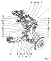
図1には、一実施例による車輪懸架装置1の概略的な図が示されている。車輪懸架装置1は、以下の構造要素:スプリングダンパ2、スタビライザ3、第1のトランスバースコントロールアーム4、第2のトランスバースコントロールアーム5、第1のタイロッド6、第2のタイロッド7、偏向レバー(ベルクランク)8、車輪支持部9、ステアリングギヤ10及び振り子式支持部11を備えている。車輪懸架装置1の構造状態が図示されている。
FIG. 1 shows a schematic view of a
第1のトランスバースコントロールアーム4は、トライアングルトランスバースコントロールアームとして成形されているとともに、上側のトランスバースコントロールアームである。第1のトランスバースコントロールアーム4は、第1のトランスバースコントロールアームストラット4a及び第2のトランスバースコントロールアームストラット4bを備えている。加えて、第1のトランスバースコントロールアーム4は、車輪支持部側の端部12及び2つの車体側の端部13a,13bを備えている。第1のトランスバースコントロールアーム4の第1のトランスバースコントロールアームストラット4aは、車輪支持部側の端部12及び車体側の端部のうちの1つの端部13aによって画成される。第1のトランスバースコントロールアーム4の第2のトランスバースコントロールアームストラット4bは、車輪支持部側の端部12及び車体側の端部のうち他の端部13bによって画成される。第1のトランスバースコントロールアーム4の両トランスバースコントロールアームストラット4a,4bは、車輪支持部側の端部12において互いに永続的に固結されている。第1のトランスバースコントロールアーム4の車体側の端部13a,13bでは、両トランスバースコントロールアームストラット4a,4bは互いに結合されていない。したがって、第1のトランスバースコントロールアーム4の第1のトランスバースコントロールアームストラット4aの車体側の端部13aと第1のトランスバースコントロールアーム4の第2のトランスバースコントロールアームストラット4bの車体側の端部13bの間には、材料のない範囲、すなわち材料のない体積がある。
The first
第1のトランスバースコントロールアーム4は、第1のトランスバースコントロールアーム4の第1のトランスバースコントロールアームストラット4aの車体側の端部13aにおいて運動学的な点15を備えており、この運動学的な点は、例えば回転継手として成形されている。第1のトランスバースコントロールアーム4は、第1のトランスバースコントロールアーム4の第2のトランスバースコントロールアームストラット4bの車体側の端部13bにおいて別の運動学的な点15を備えており、この運動学的な点は、例えば回転継手として成形されている。このとき、運動学的な点は、トランスバースコントロールアーム4,5が車輪懸架装置1の他の構造要素とリンク式に結合されることが可能なこのトランスバースコントロールアーム4,5の範囲である。車輪懸架装置1が車両において使用されれば、第1のトランスバースコントロールアーム4は、その車体側の端部13a,13bにおいて、運動学的な点15を用いて例えば車両の車体又は車両のフレームにリンク式に結合されることが可能である。第1のトランスバースコントロールアーム4の車体側の両運動学的な点15の継手の回転軸線は、互いに同軸となっている。第1のトランスバースコントロールアーム4は、この第1のトランスバースコントロールアーム4の車輪支持部側の端部12において運動学的な点15を備えており、この運動学的な点は、例えば回転継手として成形されている。第1のトランスバースコントロールアーム4は、この車輪支持部側の運動学的な点を用いて車輪支持部9にリンク式に結合されている。第1のトランスバースコントロールアーム4は、車輪懸架装置1を上方へ向けて画成している。
The first
第1のトランスバースコントロールアーム4の車体側の両端部13a,13bの間の材料のない空間には、ステアリングギヤ10の部分範囲が配置されている。このとき、ステアリングギヤ10の部分範囲は、車輪懸架装置1が車両において使用されるときに、構造状態においても、また車両動作状態においても、十分な空間がステアリングギヤ10に提供されるように、第1のトランスバースコントロールアーム4の車体側の両端部13a,13bの間に配置されており、その結果、ステアリングギヤ10は、第1のトランスバースコントロールアーム4又は車輪懸架装置1の他の構造要素に衝突しない。このとき、ステアリングギヤ10の部分範囲は、第1のトランスバースコントロールアーム4の車体側の両端部13a,13bの間で純粋に空間的に配置されており、機能的な結合は存在しない。ステアリングギヤ10は、第1のトランスバースコントロールアーム4と共に1つの平面内に位置している。
A partial range of the
ステアリングギヤ10は、第1のタイロッド6と作用結合している。したがって、ステアリングギヤ10によってもたらされる操舵運動は、第1のタイロッド6へ伝達される。第1のタイロッド6は、第1のトランスバースコントロールアーム4の第1のトランスバースコントロールアームストラット4aの下方における部分範囲に配置されている。第1のトランスバースコントロールアームストラット4aは、最大部を有する湾曲部を備えている。第1のトランスバースコントロールアームストラット4aの湾曲部は、垂直軸の方向へ向けられている。したがって、第1のトランスバースコントロールアームストラット4aの湾曲部の最大部は、第1のトランスバースコントロールアーム4上の全ての点から第2のトランスバースコントロールアーム5への最大の間隔を有している。このとき、第1のトランスバースコントロールアームストラット4aの湾曲部は、構造状態における第1のタイロッド6の空間需要にも、また、車輪懸架装置1が車両において使用される場合には車両動作状態における第1のタイロッド6の空間需要にもならう。したがって、湾曲部は、第1のタイロッド6が第1のトランスバースコントロールアーム4と衝突することがないように成形されている。
The
第1のタイロッド6は、偏向レバー8と作用結合されている。したがって、操舵運動は、第1のタイロッド6から偏向レバー8へ伝達される。偏向レバー8は、操舵運動の追加的な操舵伝達を行う。偏向レバー8は、リンク式の支持部14を用いて第1のトランスバースコントロールアーム4において可動に支持されている。さらに、偏向レバー8は、二重に湾曲されて成形されている。一方で、この成形は、操舵範囲及び車輪支持部9の形状によって偏向レバー8の範囲に固定されており、この範囲は、1つの平面内において車輪支持部9と共に配置されている。偏向レバー8の形状によって、車輪懸架装置1が車両において使用される場合には車両動作状態において、ステアリングギヤ10から車輪懸架装置1へもたらされる操舵運動を生じさせる旋回運動を行うのに十分な空間を車輪支持部9が有することが保証される。他方で、偏向レバー8のこの形状は、弾性範囲及び第1のトランスバースコントロールアーム4の形状によって、1つの平面内において第1のトランスバースコントロールアーム4と共に配置されている偏向レバー8の範囲において固定されている。偏向レバー8の形状によって、車輪懸架装置1が車両において使用される場合には車両動作状態において、第1のトランスバースコントロールアーム4が弾性運動を行うのに十分な空間を有することが保証される。換言すれば、偏向レバー8は、車輪支持部9周りのアーチと、第1のトランスバースコントロールアーム4周りのアーチとを備えている。
The
偏向レバー8は、運動学的な点15を用いて、第2のタイロッド7とリンク式に結合されている。したがって、操舵運動は、偏向レバー8から第2のタイロッド7へ伝達される。第2のタイロッド7の偏向レバー8とのこのリンク式の結合は、ボールスタッド20として成形されている。第2のタイロッド7は、別の運動学的な点15において、車輪支持部9にリンク式に作用結合されている。このリンク式の結合も、同様にボールスタッド20として成形されている。このとき、第2のタイロッド7は、両ボールスタッド20の間の中央の範囲において先細に成形されている。第2のタイロッド7を偏向レバー8に結合させるボールスタッド20の回転軸線は、第2のタイロッド7を車輪支持部9にリンク式に結合させるボールスタッド20の回転軸線に対してねじれている。操舵運動は、第2のタイロッド7から車輪支持部9へ伝達され、これにより、車輪支持部9が右方又は左方への旋回運動を行う。車輪懸架装置が車両において使用されれば、この旋回運動によって、車輪支持部9に結合された車輪が少なくとも±50°〜±90°の操舵角を設定することが可能である。
The deflection lever 8 is linked to the second tie rod 7 using a
第2のトランスバースコントロールアーム5は、下側のトランスバースコントロールアームであるとともに、トライアングルトランスバースコントロールアームとして成形されている。加えて、第2のトランスバースコントロールアーム5は、Y字状に類似して成形されている。第2のトランスバースコントロールアーム5は、1つの車輪支持部側の端部12と、2つの車体側の端部13とを備えている。第2のトランスバースコントロールアーム5の車輪支持部側の端部12は、運動学的な点15を備えている。車輪支持部9は、ボールスタッド又はボールジョイントとして成形されている運動学的な点15を用いて第2のトランスバースコントロールアーム5とリンク式に結合されている。車体側の各端部13は、運動学的な点15を備えている。車輪懸架装置1が車両において使用される場合には、この運動学的な点15を用いて、第2のトランスバースコントロールアーム5は、車両の車体において支持されている。第2のトランスバースコントロールアーム5は、第1のトランスバースコントロールアーム4とは異なるように成形されている。第2のトランスバースコントロールアーム5は、第2のトランスバースコントロールアーム5の車体側の両端部13の近傍において結合要素19を備えている。
The second
そのほか、第2のトランスバースコントロールアーム5は、ウェブ16を備えている。ウェブ16は、車輪支持部側の端部12の運動学的な点15から、振り子式支持部11が第2のトランスバースコントロールアーム5に結合されている結合箇所17まで延在している。第2のトランスバースコントロールアーム5のウェブ16は更に結合箇所18を備えており、この結合箇所では、スプリングダンパ2が第2のトランスバースコントロールアーム5に結合されている。ウェブ16は先細部を備えており、この先細部は、結合箇所18から第2のトランスバースコントロールアーム5の車輪支持部側の端部12の運動学的な点15まで延在している。したがって、結合箇所18では、ウェブは、第2のトランスバースコントロールアーム5の車輪支持部側の端部12の運動学的な点15におけるよりも幅広となっている。ウェブ16の形状は、車輪支持部9の操舵範囲にならうものである。車両動作状態において最大の操舵角が車輪支持部9において設定されていれば、ウェブ16の形状は、車輪懸架装置1が車両において使用される場合に、車輪支持部9又は車輪支持部9に結合された車輪が第2のトランスバースコントロールアーム5のウェブ16との衝突に至らない。
In addition, the second
第2のトランスバースコントロールアーム5の結合箇所17では、振り子式支持部11が第2のトランスバースコントロールアーム5に結合されている。振り子式支持部11は、図示の構造状態において、第2のトランスバースコントロールアーム5上において垂直に配置されている。振り子式支持部11にはスタビライザ3が結合されている。したがって、スタビライザ3は、第2のトランスバースコントロールアーム5に対して離間し、第1のトランスバースコントロールアーム4の方向にずらして配置されている。スタビライザ3は、当該スタビライザが車輪懸架装置1のために使用可能な構造空間を有効に利用するように成形されている。したがって、スタビライザ3の形状は、構造状態においても、また、車輪懸架装置1が車両において使用される場合に車両動作状態においても、車輪懸架装置1のその他の構造要素の構造空間需要にならっている。
At the joint 17 of the second
結合箇所18では、スプリングダンパ2が第2のトランスバースコントロールアーム5に結合されている。このとき、スプリングダンパ2は通常どおりに成形されており、結合箇所18は、スプリングダンパ2を下方へ向けて画成している。スプリングダンパ2は、第2のトランスバースコントロールアーム5上で垂直に位置決めされておらず、鋭角をもって垂直からずれている。したがって、スプリングダンパ2は、下側のトランスバースコントロールアーム5に対して傾斜して配置されている。スプリングダンパ2は結合点を備えており、この結合点は、結合箇所18の向かい側に位置しているとともに、スプリングダンパ2を上方へ向けて画成している。車輪懸架装置1が車両において使用される場合には、この結合点において、スプリングダンパ2が車両の車体において支持されている。
At the
車輪懸架装置1をその全体において見ると、車輪懸架装置1の各構造要素は、使用可能な構造空間が有効に利用されるように車輪懸架装置1内に配置されている。したがって、車輪懸架装置1の個々の構造要素は互いに対して密に構成されており、構造要素の互いに対する間隔は、構造状態においても、また車両動作状態においても、各個々の構造要素の空間需要にならっている。
When the
ここに図示された実施例は、例示的にのみ選択されている。例えば、車輪支持部は、図示されたものと異なるように成形されることが可能である。第2のトランスバースコントロールアームも、そのウェブの範囲において他の形状を有することが可能である。例えば、運動学的な点は、他の適当な継手によって成形されることが可能である。例えば、第1のトランスバースコントロールアームの第1のトランスバースコントロールアームストラットの湾曲部が図示のものとは異なるように延びることが可能である。 The embodiment shown here has been selected by way of example only. For example, the wheel supports can be shaped differently than shown. The second transverse control arm can also have other shapes in the area of its web. For example, kinematic points can be shaped by other suitable joints. For example, the curvature of the first transverse control arm struts of the first transverse control arm can extend differently than shown.
1 車輪懸架装置
2 スプリングダンパ
3 スタビライザ
4 第1のトランスバースコントロールアーム
4a 第1のトランスバースコントロールアームストラット
4b 第2のトランスバースコントロールアームストラット
5 第2のトランスバースコントロールアーム
6 第1のタイロッド
7 第2のタイロッド
8 偏向レバー
9 車輪支持部
10 ステアリングギヤ
11 振り子式支持部
12 車輪支持部側の端部
13 車体側の端部
13a 車体側の端部
13b 車体側の端部
14 リンク式の支持部
15 運動学的な点
16 ウェブ
17 結合箇所
18 結合箇所
19 結合要素
20 ボールスタッド
Claims (9)
前記ステアリングギヤ(10)が1つの平面内で前記第1のトランスバースコントロールアーム(4)と共に配置されており、前記ステアリングギヤ(10)が、前記第1のトランスバースコントロールアーム(4)の前記第1のトランスバースコントロールアームストラット(4a)の車体側の端部(13a)と前記第1のトランスバースコントロールアーム(4)の前記第2のトランスバースコントロールアームストラット(4b)の車体側の端部(13b)の間の部分範囲に配置されていることを特徴とする車輪懸架装置。 A wheel suspension (1) for a vehicle, comprising a spring damper (2), a first transverse control arm strut (4a) and a first transverse control arm strut (4b). Control arm (4), second transverse control arm (5), first tie rod (6), second tie rod (7), deflection lever (8), wheel support (9) , A steering gear (10), and a pendulum-type support (11), each transverse control arm (4, 5) having one end (12) on the wheel support and two ends on the vehicle body. In the above-mentioned wheel suspension device, comprising a portion (13, 13a, 13b)
The steering gear (10) is arranged in one plane with the first transverse control arm (4), and the steering gear (10) is arranged in the plane of the first transverse control arm (4). A vehicle-side end of a first transverse control arm strut (4a) and a vehicle-side end of the second transverse control arm strut (4b) of the first transverse control arm (4). Wheel suspension, characterized in that it is arranged in a partial area between the parts (13b).
Applications Claiming Priority (3)
| Application Number | Priority Date | Filing Date | Title |
|---|---|---|---|
| DE102015209844.3 | 2015-05-28 | ||
| DE102015209844.3A DE102015209844A1 (en) | 2015-05-28 | 2015-05-28 | suspension structure |
| PCT/EP2016/059153 WO2016188686A1 (en) | 2015-05-28 | 2016-04-25 | Wheel suspension system |
Publications (3)
| Publication Number | Publication Date |
|---|---|
| JP2018516201A JP2018516201A (en) | 2018-06-21 |
| JP2018516201A5 JP2018516201A5 (en) | 2019-01-24 |
| JP6655101B2 true JP6655101B2 (en) | 2020-02-26 |
Family
ID=55806367
Family Applications (1)
| Application Number | Title | Priority Date | Filing Date |
|---|---|---|---|
| JP2017561740A Active JP6655101B2 (en) | 2015-05-28 | 2016-04-25 | Wheel suspension |
Country Status (7)
| Country | Link |
|---|---|
| US (1) | US10414224B2 (en) |
| EP (1) | EP3303098B1 (en) |
| JP (1) | JP6655101B2 (en) |
| KR (1) | KR20180014022A (en) |
| CN (1) | CN107690395B (en) |
| DE (1) | DE102015209844A1 (en) |
| WO (1) | WO2016188686A1 (en) |
Families Citing this family (11)
| Publication number | Priority date | Publication date | Assignee | Title |
|---|---|---|---|---|
| US9440671B2 (en) | 2012-09-20 | 2016-09-13 | Polaris Industries Inc. | Vehicle |
| WO2014047488A1 (en) | 2012-09-20 | 2014-03-27 | Polaris Industries Inc. | Utiliy vehicle |
| DE102015209845A1 (en) * | 2015-05-28 | 2016-12-01 | Zf Friedrichshafen Ag | wishbone |
| DE102017200867B4 (en) * | 2017-01-19 | 2020-09-24 | Audi Ag | Steering arrangement for a vehicle |
| DE102017213799A1 (en) * | 2017-08-08 | 2019-02-14 | Zf Friedrichshafen Ag | Arm |
| US10793181B2 (en) | 2018-02-13 | 2020-10-06 | Polaris Industries Inc. | All-terrain vehicle |
| DE102018205429B4 (en) * | 2018-04-11 | 2019-10-24 | Ford Global Technologies, Llc | Rear wheel suspension system of a motor vehicle, in particular of an electrically driven motor vehicle |
| DE102018206402B4 (en) * | 2018-04-25 | 2021-08-19 | Audi Ag | Wheel suspension for a motor vehicle and a corresponding motor vehicle |
| DE102020200374A1 (en) | 2020-01-14 | 2021-07-15 | Zf Friedrichshafen Ag | Steerable wheel suspension, vehicle axle and vehicle |
| KR20230060647A (en) * | 2021-10-28 | 2023-05-08 | 현대자동차주식회사 | Independent Corner Module |
| CN216401548U (en) * | 2021-11-22 | 2022-04-29 | 宁德时代新能源科技股份有限公司 | Steering knuckle and steering mechanism |
Family Cites Families (13)
| Publication number | Priority date | Publication date | Assignee | Title |
|---|---|---|---|---|
| US3379455A (en) | 1966-06-01 | 1968-04-23 | Gen Motors Corp | Independent dirigible wheel suspension |
| US5496055A (en) * | 1992-04-28 | 1996-03-05 | Honda Giken Kogyo Kabushiki Kaisha | Suspension system for steered wheel |
| KR0136260B1 (en) * | 1992-12-14 | 1998-05-01 | 전성원 | Suspension apparatus |
| US5516130A (en) * | 1994-12-22 | 1996-05-14 | Interstate Forging Industries Inc. | Forged control arm |
| US5609331A (en) | 1995-09-05 | 1997-03-11 | Ford Motor Company | Torsion spring adjustment apparatus |
| DE20023579U1 (en) | 1999-05-03 | 2004-12-16 | Dr.Ing.H.C. F. Porsche Ag | Wheel suspension for a front axle of a motor vehicle |
| KR100457316B1 (en) * | 2002-09-05 | 2004-11-16 | 현대자동차주식회사 | Front whell suspension system using steering gear frame |
| JP2005053471A (en) | 2003-07-23 | 2005-03-03 | Nissan Motor Co Ltd | Steering device of vehicle |
| WO2011003387A1 (en) * | 2009-07-06 | 2011-01-13 | Ksm Castings Gmbh | Axle support, especially front axle support for motor vehicles |
| EP2338707A1 (en) | 2009-12-22 | 2011-06-29 | Iveco S.p.A. | Suspension unit for a front axle of an industrial or commercial vehicle with upper and lower V-shaped arms and a transverse leaf spring |
| CN103287493A (en) | 2013-06-25 | 2013-09-11 | 盐城工学院 | Steering driving wheel |
| DE102013216029B4 (en) * | 2013-08-13 | 2024-08-14 | Bayerische Motoren Werke Aktiengesellschaft | Steerable front axle for wheels of a two-track motor vehicle and two-track motor vehicle with such a front axle |
| DE102015203632A1 (en) | 2015-03-02 | 2016-09-08 | Zf Friedrichshafen Ag | Independent suspension with high steering angle |
-
2015
- 2015-05-28 DE DE102015209844.3A patent/DE102015209844A1/en not_active Withdrawn
-
2016
- 2016-04-25 EP EP16717967.0A patent/EP3303098B1/en active Active
- 2016-04-25 CN CN201680030830.6A patent/CN107690395B/en active Active
- 2016-04-25 JP JP2017561740A patent/JP6655101B2/en active Active
- 2016-04-25 US US15/577,014 patent/US10414224B2/en active Active
- 2016-04-25 WO PCT/EP2016/059153 patent/WO2016188686A1/en active Application Filing
- 2016-04-25 KR KR1020177037319A patent/KR20180014022A/en active IP Right Grant
Also Published As
| Publication number | Publication date |
|---|---|
| KR20180014022A (en) | 2018-02-07 |
| CN107690395B (en) | 2020-06-02 |
| EP3303098B1 (en) | 2019-07-17 |
| CN107690395A (en) | 2018-02-13 |
| US10414224B2 (en) | 2019-09-17 |
| JP2018516201A (en) | 2018-06-21 |
| DE102015209844A1 (en) | 2016-12-01 |
| US20180154717A1 (en) | 2018-06-07 |
| EP3303098A1 (en) | 2018-04-11 |
| WO2016188686A1 (en) | 2016-12-01 |
Similar Documents
| Publication | Publication Date | Title |
|---|---|---|
| JP6655101B2 (en) | Wheel suspension | |
| JP4990901B2 (en) | Vehicle suspension system | |
| JP6022047B2 (en) | Adjustable wheel suspension for axle wheels of prime mover vehicles | |
| CN206812741U (en) | The double yoke suspensions of electric automobile | |
| CN104943490A (en) | Single wheel suspension of vehicle and rear axle including single wheel suspension, and vehicle with same | |
| JP2008504166A5 (en) | Support system and suspension system for automobile | |
| JP6330861B2 (en) | Automobile front suspension structure | |
| JP6091790B2 (en) | Active control suspension | |
| JP2008018924A (en) | Suspension device | |
| KR20140068065A (en) | Steerable twist-beam rear suspension | |
| ES2772255T3 (en) | Pneumatic tandem axle suspension for a pair of rear axles of a vehicle, in particular a heavy goods vehicle | |
| JP2019501069A (en) | Wheel suspension | |
| JPH10278526A (en) | Suspension for vehicle | |
| JP2004155258A (en) | Suspension device | |
| CN108058555B (en) | Suspension and vehicle | |
| JP2018516199A (en) | Transverse control arm | |
| EP3489046B1 (en) | A quadrilateral-type suspension for a steerable wheel of a motor-vehicle | |
| ITRM990546A1 (en) | PASSIVE ROLLER DAMPING WITH AT LEAST ONE VEHICLE AXLE SHOCK ABSORBER. | |
| CN113795394B (en) | Rear axle for a double-track vehicle and double-track vehicle having such a rear axle | |
| JPS6071310A (en) | Trailing link type beam suspension | |
| JP4647279B2 (en) | Rear suspension | |
| CN107804129A (en) | A kind of multi link rear-suspension system and vehicle | |
| JP2013056656A (en) | Coupled torsion beam axle with improved compliance characteristics | |
| JPH02262409A (en) | Torsion beam axle suspension of vehicle | |
| ITRM990545A1 (en) | PASSIVE ROLLER DAMPING WITH SHOCK ABSORBER FOR VEHICLE AXLE. |
Legal Events
| Date | Code | Title | Description |
|---|---|---|---|
| A521 | Request for written amendment filed |
Free format text: JAPANESE INTERMEDIATE CODE: A523 Effective date: 20181204 |
|
| A621 | Written request for application examination |
Free format text: JAPANESE INTERMEDIATE CODE: A621 Effective date: 20181204 |
|
| A977 | Report on retrieval |
Free format text: JAPANESE INTERMEDIATE CODE: A971007 Effective date: 20191206 |
|
| TRDD | Decision of grant or rejection written | ||
| A01 | Written decision to grant a patent or to grant a registration (utility model) |
Free format text: JAPANESE INTERMEDIATE CODE: A01 Effective date: 20200122 |
|
| A61 | First payment of annual fees (during grant procedure) |
Free format text: JAPANESE INTERMEDIATE CODE: A61 Effective date: 20200131 |
|
| R150 | Certificate of patent or registration of utility model |
Ref document number: 6655101 Country of ref document: JP Free format text: JAPANESE INTERMEDIATE CODE: R150 |
|
| R250 | Receipt of annual fees |
Free format text: JAPANESE INTERMEDIATE CODE: R250 |
|
| R250 | Receipt of annual fees |
Free format text: JAPANESE INTERMEDIATE CODE: R250 |