JP6654792B2 - Anti-vibration device - Google Patents

Anti-vibration device Download PDF

Info

Publication number
JP6654792B2
JP6654792B2 JP2014125196A JP2014125196A JP6654792B2 JP 6654792 B2 JP6654792 B2 JP 6654792B2 JP 2014125196 A JP2014125196 A JP 2014125196A JP 2014125196 A JP2014125196 A JP 2014125196A JP 6654792 B2 JP6654792 B2 JP 6654792B2
Authority
JP
Japan
Prior art keywords
liquid
restriction passage
vibration
flow
liquid chamber
Prior art date
Legal status (The legal status is an assumption and is not a legal conclusion. Google has not performed a legal analysis and makes no representation as to the accuracy of the status listed.)
Active
Application number
JP2014125196A
Other languages
Japanese (ja)
Other versions
JP2016003726A (en
Inventor
植木 哲
哲 植木
Current Assignee (The listed assignees may be inaccurate. Google has not performed a legal analysis and makes no representation or warranty as to the accuracy of the list.)
Bridgestone Corp
Original Assignee
Bridgestone Corp
Priority date (The priority date is an assumption and is not a legal conclusion. Google has not performed a legal analysis and makes no representation as to the accuracy of the date listed.)
Filing date
Publication date
Application filed by Bridgestone Corp filed Critical Bridgestone Corp
Priority to JP2014125196A priority Critical patent/JP6654792B2/en
Publication of JP2016003726A publication Critical patent/JP2016003726A/en
Application granted granted Critical
Publication of JP6654792B2 publication Critical patent/JP6654792B2/en
Active legal-status Critical Current
Anticipated expiration legal-status Critical

Links

Images

Description

本発明は、例えば自動車や産業機械等に適用され、エンジン等の振動発生部の振動を吸収および減衰する防振装置に関する。   The present invention relates to an anti-vibration device that is applied to, for example, an automobile or an industrial machine, and absorbs and attenuates vibration of a vibration generating unit such as an engine.

従来から、この種の防振装置として、例えば下記特許文献1記載の構成が知られている。この防振装置は、振動発生部および振動受部のうちの一方に連結される筒状の第1取付け部材、および他方に連結される第2取付け部材と、これらの両取付け部材を連結する弾性体と、液体が封入される第1取付け部材内の液室を、第1液室および第2液室に仕切る仕切り部材と、を備えている。仕切り部材には、両液室を互いに連通する制限通路が形成されている。制限通路は、第1振動の入力に対して共振を生じさせる第1制限通路と、振幅が前記第1振動の振幅よりも大きい第2振動の入力に対して共振を生じさせる第2制限通路と、を備えている。仕切り部材には、プランジャ部材が設けられている。
この防振装置では、振動が入力されたときにプランジャ部材を移動させて第1制限通路を開閉することで、両液室の間で液体が流通する制限通路を切り替える。これにより、第1振動の入力時には液体が第1制限通路を流通し、第2振動の入力時には液体が第2制限通路を流通する。
2. Description of the Related Art Conventionally, as a vibration isolator of this type, for example, a configuration described in Patent Literature 1 below is known. This vibration isolator includes a cylindrical first mounting member connected to one of the vibration generating portion and the vibration receiving portion, a second mounting member connected to the other, and an elasticity connecting these two mounting members. A body and a partition member that partitions a liquid chamber in the first mounting member into which the liquid is sealed into a first liquid chamber and a second liquid chamber. The partition member has a restriction passage that connects the two liquid chambers to each other. The restriction passage includes a first restriction passage that causes resonance with respect to the input of the first vibration, and a second restriction passage that causes resonance with respect to the input of the second vibration whose amplitude is larger than the amplitude of the first vibration. , Is provided. The partition member is provided with a plunger member.
In this vibration isolator, when vibration is input, the plunger member is moved to open and close the first restriction passage, thereby switching the restriction passage through which the liquid flows between the two liquid chambers. Thus, when the first vibration is input, the liquid flows through the first restriction passage, and when the second vibration is input, the liquid flows through the second restriction passage.

特開2007−120598号公報JP 2007-120598 A

しかしながら、前記従来の防振装置には、構造の簡素化、製造の容易化について改善の余地がある。   However, the conventional vibration isolator has room for improvement in simplification of the structure and simplification of manufacturing.

本発明は、前述した事情に鑑みてなされたものであって、構造の簡素化および製造の簡便化を図ることができる防振装置を提供することを目的とする。   The present invention has been made in view of the above circumstances, and has as its object to provide an anti-vibration device capable of simplifying a structure and simplifying manufacturing.

前記課題を解決するために、本発明は以下の手段を提案している。
本発明に係る防振装置は、振動発生部および振動受部のうちの一方に連結される筒状の第1取付け部材、および他方に連結される第2取付け部材と、これらの両取付け部材を連結する弾性体と、液体が封入される前記第1取付け部材内の液室を、第1液室および第2液室に仕切る仕切り部材と、を備え、前記第1液室および前記第2液室のうちの少なくとも一方は、前記弾性体を壁面の一部に有し、前記仕切り部材には、前記第1液室と前記第2液室とを連通する制限通路が形成され、前記制限通路として、第1振動の入力に対して共振を生じさせる第1制限通路と、振幅が前記第1振動の振幅よりも大きい第2振動の入力に対して共振を生じさせる第2制限通路と、を備え、前記第1制限通路には、前記仕切り部材に固定され、前記第1制限通路内を、前記第1液室および前記第2液室のうちの一方から他方に向かう第1側に向けて流通して整流された液体の流れを流速に応じて抑制する流体ダイオードと、前記第1制限通路を閉塞する弾性薄膜と、が設けられ、前記第2振動が入力されたときに、液体が前記第1液室と前記第2液室との間で前記第1制限通路を通して前記弾性薄膜を変形させながら流通可能であることを特徴とする。
In order to solve the above problems, the present invention proposes the following means.
The vibration isolator according to the present invention includes a cylindrical first mounting member connected to one of the vibration generating unit and the vibration receiving unit, a second mounting member connected to the other, and both of these mounting members. An elastic body to be connected, and a partition member for partitioning a liquid chamber in the first mounting member in which liquid is sealed into a first liquid chamber and a second liquid chamber, wherein the first liquid chamber and the second liquid are provided. At least one of the chambers has the elastic body on a part of a wall surface, and the partitioning member has a restriction passage communicating between the first liquid chamber and the second liquid chamber. A first restriction passage that causes resonance with respect to the input of the first vibration, and a second restriction passage that causes resonance with respect to the input of the second vibration whose amplitude is larger than the amplitude of the first vibration. provided, wherein the first restricting passage, is fixed to the partition member, the first system The passage, said first fluid chamber and the second liquid chamber while inhibiting a flow of liquid that has been rectified and distributed toward the first side toward the other in response to the flow rate from the fluid diodes of the An elastic thin film for closing the first restriction passage, wherein when the second vibration is input, the liquid passes through the first restriction passage between the first liquid chamber and the second liquid chamber. It can be distributed while deforming the elastic thin film.

この場合、振動が入力されると、第1取付け部材と第2取付け部材とが、弾性体を弾性変形させながら相対的に変位する。このとき液体が、第1液室と第2液室との間で、第1制限通路を通して流通しようとする。
ここで、第1振動が入力された場合、第1振動の振幅に応じ、単位時間あたりに少量の液体が第1制限通路内に流入しようとする。その結果、第1制限通路内を流通する液体の流速の上昇が抑制される。したがって、この防振装置のような、第1制限通路に流体ダイオードが設けられているような構成であっても、液体が流れの向きによらず第1制限通路内を円滑に流通する。このとき液体は、その液圧に基づいて弾性薄膜を弾性変形させ、液圧を、弾性薄膜を挟んだ反対側に位置する他の液体に伝達させて第1制限通路内を流通する。これにより、液体に、第1制限通路を積極的に流通させることが可能になり、第1制限通路内で共振を生じさせて第1振動を吸収および減衰することができる。
一方、第2振動が入力された場合、第2振動の振幅に応じ、単位時間あたりに多量の液体が第1制限通路内に流入しようとする。その結果、第1制限通路内を流通する液体の流速が高められる。すると、第1制限通路を通して第1液室と第2液室との間を往来する液体のうち、第1制限通路内を第1側に向かう液体の流れが流体ダイオードによって抑制される。その結果、第1制限通路を通して第1液室と第2液室との間を液体が往来するときに、第1側に向けて流通する液体よりも、第1側の反対側である第2側に向けて流通する液体が第1制限通路内を円滑に流通し、弾性薄膜が第2側に向けて弾性変形する。第2振動が入力され続けて液体が第1制限通路を繰り返し往来すると、弾性薄膜の第2側に向けた変形量が徐々に大きくなり、弾性薄膜が徐々に第2側に向けて変形し難くなる。したがって、例えば、液体が第1制限通路を第2側に向けて流通しようとするときに、弾性薄膜に、この弾性薄膜に対して第1側に位置する液体の液圧が作用しても、弾性薄膜が第2側に向けて変形し難くなり、弾性薄膜に対して第1側に位置する液体の液圧が第2側に位置する液体に伝達され難くなる。その結果、第1制限通路を通した液体の流通が阻害される。これにより、第1制限通路を通して液体を流通させ難くして、第2制限通路を通して液体を流通させ易くすることができる。このとき、第2制限通路内を液体が流通することで第2制限通路内で共振を生じさせ、第2振動を吸収および減衰することができる。
以上のように、前記従来技術のようなプランジャ部材を仕切り部材に設けるのに代えて、第1制限通路に流体ダイオードおよび弾性薄膜を設けることで、第1振動および第2振動の両方を吸収および減衰させることができる。これにより、防振装置の構造の簡素化および製造の簡便化を図ることができる。
In this case, when vibration is input, the first mounting member and the second mounting member are relatively displaced while elastically deforming the elastic body. At this time, the liquid tries to circulate through the first restriction passage between the first liquid chamber and the second liquid chamber.
Here, when the first vibration is input, a small amount of liquid attempts to flow into the first restriction passage per unit time according to the amplitude of the first vibration. As a result, an increase in the flow velocity of the liquid flowing in the first restriction passage is suppressed. Therefore, even in a configuration in which the fluid diode is provided in the first restriction passage such as the vibration isolator, the liquid flows smoothly in the first restriction passage regardless of the flow direction. At this time, the liquid elastically deforms the elastic thin film based on the liquid pressure, transmits the liquid pressure to another liquid located on the opposite side of the elastic thin film, and flows through the first restriction passage. This makes it possible to positively circulate the liquid through the first restriction passage, and to cause resonance in the first restriction passage to absorb and attenuate the first vibration.
On the other hand, when the second vibration is input, a large amount of liquid attempts to flow into the first restriction passage per unit time according to the amplitude of the second vibration. As a result, the flow velocity of the liquid flowing in the first restriction passage is increased. Then, among the liquids flowing between the first liquid chamber and the second liquid chamber through the first restriction passage, the flow of the liquid toward the first side in the first restriction passage is suppressed by the fluid diode. As a result, when the liquid flows between the first liquid chamber and the second liquid chamber through the first restriction passage, the second liquid, which is on the opposite side of the first side than the liquid flowing toward the first side. The liquid flowing toward the side smoothly flows in the first restriction passage, and the elastic thin film elastically deforms toward the second side. When the second vibration is continuously input and the liquid repeatedly travels through the first restriction passage, the amount of deformation of the elastic thin film toward the second side gradually increases, and the elastic thin film is less likely to gradually deform toward the second side. Become. Therefore, for example, when the liquid attempts to flow through the first restriction passage toward the second side, even if the liquid pressure of the liquid located on the first side acts on the elastic thin film, The elastic thin film is less likely to deform toward the second side, and the liquid pressure of the liquid located on the first side relative to the elastic thin film is less likely to be transmitted to the liquid located on the second side. As a result, the flow of the liquid through the first restriction passage is hindered. This makes it difficult for the liquid to flow through the first restriction passage, and makes it easier for the liquid to flow through the second restriction passage. At this time, when the liquid flows in the second restriction passage, resonance occurs in the second restriction passage, and the second vibration can be absorbed and attenuated.
As described above, instead of providing the plunger member in the partition member as in the prior art, a fluid diode and an elastic thin film are provided in the first restriction passage to absorb and absorb both the first vibration and the second vibration. Can be attenuated. Thereby, simplification of the structure of the vibration isolator and simplification of manufacturing can be achieved.

前記第1制限通路には、前記弾性薄膜が、前記第1側の反対側である第2側に向けて変形したときに、前記弾性薄膜の更なる前記第2側に向けた変形を規制するストッパが設けられていてもよい。   The first restriction passage restricts further deformation of the elastic thin film toward the second side when the elastic thin film is deformed toward the second side opposite to the first side. A stopper may be provided.

この場合、第1制限通路にストッパが設けられているので、ストッパにより弾性薄膜の変形量を精度良く規制することができる。これにより、第2振動が入力されたときに、第1制限通路を通した液体の流通を高精度に阻害することができる。   In this case, since the stopper is provided in the first restriction passage, the amount of deformation of the elastic thin film can be accurately regulated by the stopper. Thereby, when the second vibration is input, the flow of the liquid through the first restriction passage can be hindered with high accuracy.

前記弾性薄膜は、前記第1制限通路の流路軸方向に沿った縦断面視において、前記流路軸方向に凸となっていてもよい。   The elastic thin film may be convex in the flow channel axial direction in a longitudinal sectional view along the flow channel axial direction of the first restriction passage.

この場合、弾性薄膜が、前記縦断面視において、前記流路軸方向に凸となっているので、弾性薄膜を、この弾性薄膜の形状に基づいて、前記流路軸方向に容易に変形させることができる。したがって、例えば、第1振動が入力されたときに、第1制限通路を流通する液体の液圧によって弾性薄膜を確実に変形させることができる。これにより、液体に第1制限通路内を円滑に流通させることができる。   In this case, since the elastic thin film is convex in the axial direction of the flow channel in the longitudinal sectional view, the elastic thin film can be easily deformed in the axial direction of the flow channel based on the shape of the elastic thin film. Can be. Therefore, for example, when the first vibration is input, the elastic thin film can be reliably deformed by the liquid pressure of the liquid flowing through the first restriction passage. This allows the liquid to flow smoothly in the first restriction passage.

本発明によれば、構造の簡素化および製造の簡便化を図ることができる。   ADVANTAGE OF THE INVENTION According to this invention, simplification of a structure and simplification of manufacture can be achieved.

本発明の第1実施形態に係る防振装置の縦断面図である。It is a longitudinal section of a vibration control device concerning a 1st embodiment of the present invention. 図1に示す防振装置を構成する仕切り部材に設けられた流体ダイオードの拡大図である。FIG. 2 is an enlarged view of a fluid diode provided on a partition member constituting the vibration isolator shown in FIG. 1. 図1に示す防振装置の模式図である。It is a schematic diagram of the vibration isolator shown in FIG. 図1に示す防振装置の模式図であって、アイドル振動が入力された場合における液体の流れを説明する図である。FIG. 2 is a schematic diagram of the vibration isolator illustrated in FIG. 1 and illustrates a flow of a liquid when idle vibration is input. 図1に示す防振装置の模式図であって、シェイク振動が入力された場合における液体の流れを説明する図である。FIG. 2 is a schematic diagram of the vibration isolator illustrated in FIG. 1, illustrating a flow of a liquid when shake vibration is input. 本発明の第2実施形態に係る防振装置の模式図である。It is a mimetic diagram of a vibration control device concerning a 2nd embodiment of the present invention. 本発明の第3実施形態に係る防振装置の模式図である。It is a schematic diagram of a vibration isolator according to a third embodiment of the present invention. 本発明の第4実施形態に係る防振装置の縦断面図である。It is a longitudinal section of a vibration control device concerning a 4th embodiment of the present invention. 図8に示すA−A断面矢視図である。FIG. 9 is a sectional view taken along the line AA shown in FIG. 図8に示す防振装置を構成する仕切り部材に設けられた渦室の模式図であって、整流路から流入される液体の流速が低い場合における液体の流れを説明する図である。FIG. 9 is a schematic diagram of a vortex chamber provided in a partition member that constitutes the vibration isolator illustrated in FIG. 8, and is a diagram illustrating a flow of a liquid when the flow velocity of the liquid flowing from the rectifying path is low. 図8に示す防振装置を構成する仕切り部材に設けられた渦室の模式図であって、整流路から流入される液体の流速が高い場合における液体の流れを説明する図である。FIG. 9 is a schematic diagram of a vortex chamber provided in a partition member included in the vibration isolator illustrated in FIG. 8, illustrating a flow of a liquid when the flow velocity of the liquid flowing from the rectifying path is high. 図8に示す防振装置を構成する仕切り部材に設けられた渦室の模式図であって、連通孔から流入される液体の流れを説明する図である。FIG. 9 is a schematic diagram of a vortex chamber provided in a partition member included in the vibration isolator illustrated in FIG. 8, illustrating a flow of a liquid flowing from a communication hole.

(第1実施形態)
以下、本発明に係る防振装置の第1実施形態を、図1から図5を参照しながら説明する。
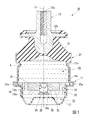
この防振装置10は、図1から図3に示すように、振動発生部および振動受部のうちのいずれか一方に連結される筒状の第1取付け部材11、および他方に連結される第2取付け部材12と、これらの両取付け部材11、12同士を互いに連結する弾性体13と、液体Lが封入される第1取付け部材11内の液室を、弾性体13を壁面の一部に有する主液室(第1液室)14、および副液室(第2液室)15に仕切る仕切り部材16と、を備えている。
(1st Embodiment)
Hereinafter, a first embodiment of a vibration isolator according to the present invention will be described with reference to FIGS. 1 to 5.
As shown in FIGS. 1 to 3, the vibration isolator 10 includes a cylindrical first mounting member 11 connected to one of a vibration generating unit and a vibration receiving unit, and a first mounting member 11 connected to the other. 2 mounting member 12, an elastic body 13 for connecting these two mounting members 11, 12 to each other, and a liquid chamber in the first mounting member 11 in which the liquid L is sealed. And a partition member 16 for partitioning into a main liquid chamber (first liquid chamber) 14 and a sub liquid chamber (second liquid chamber) 15.

図示の例では、第2取付け部材12は柱状に形成されるとともに、弾性体13は筒状に形成され、第1取付け部材11、第2取付け部材12および弾性体13は、共通軸と同軸に配設されている。以下、この共通軸を軸線(第1取付け部材の軸線、第1制限通路の流路軸)Oといい、軸線O方向に沿う主液室14側を一方側といい、副液室15側を他方側といい、軸線Oに直交する方向を径方向(第1制限通路の径方向)といい、軸線O回りに周回する方向を周方向(第1制限通路の周方向)という。   In the illustrated example, the second mounting member 12 is formed in a columnar shape, the elastic body 13 is formed in a cylindrical shape, and the first mounting member 11, the second mounting member 12, and the elastic body 13 are coaxial with a common axis. It is arranged. Hereinafter, this common shaft is referred to as an axis O (the axis of the first mounting member, the flow path axis of the first restriction passage) O, the main liquid chamber 14 side along the axis O direction is referred to as one side, and the sub liquid chamber 15 side. The direction orthogonal to the axis O is referred to as a radial direction (the radial direction of the first restriction passage), and the direction around the axis O is referred to as a circumferential direction (the peripheral direction of the first restriction passage).

なお、この防振装置10が例えば自動車に装着される場合には、第2取付け部材12が振動発生部としてのエンジンに連結される一方、第1取付け部材11が図示しないブラケットを介して振動受部としての車体に連結され、エンジンの振動が車体に伝達するのを抑える。この防振装置10は、第1取付け部材11の前記液室に、例えばエチレングリコール、水、シリコーンオイル等の液体Lが封入された液体封入型である。   When the vibration isolator 10 is mounted on, for example, an automobile, the second mounting member 12 is connected to an engine as a vibration generating unit, while the first mounting member 11 is connected to a vibration receiver via a bracket (not shown). It is connected to the vehicle body as a part, and suppresses transmission of engine vibration to the vehicle body. This vibration isolator 10 is of a liquid sealing type in which a liquid L such as ethylene glycol, water, silicone oil or the like is sealed in the liquid chamber of the first mounting member 11.

第1取付け部材11は、軸線O方向に沿って、一方側に位置する一方側外筒体21と、他方側に位置する他方側外筒体22と、を備えている。
一方側外筒体21における一方側の端部には、前記弾性体13が液密状態で連結されていて、この弾性体13により一方側外筒体21の一方側の開口部が閉塞されている。一方側外筒体21のうち、他方側の端部21aは、他の部分より大径に形成されている。そして、一方側外筒体21の内部が前記主液室14となっている。主液室14の液圧は、振動の入力時に、弾性体13が変形してこの主液室14の内容積が変化することで変動する。なお一方側外筒体21において、弾性体13が連結された部分に対して他方側から連なる部分には、全周にわたって連続して延びる環状溝21bが形成されている。
The first mounting member 11 includes one outer cylinder 21 located on one side and the other outer cylinder 22 located on the other side along the axis O direction.
The elastic body 13 is connected to one end of the one outer cylinder 21 in a liquid-tight manner, and the opening of one side of the one outer cylinder 21 is closed by the elastic body 13. I have. The end 21a on the other side of the one outer cylinder 21 is formed to have a larger diameter than the other part. The inside of the one outer cylinder 21 is the main liquid chamber 14. The hydraulic pressure of the main liquid chamber 14 fluctuates when the elastic body 13 is deformed and the internal volume of the main liquid chamber 14 changes when vibration is input. In the one outer cylindrical body 21, an annular groove 21b extending continuously over the entire circumference is formed in a portion connected from the other side to the portion to which the elastic body 13 is connected.

他方側外筒体22における他方側の端部には、ダイヤフラム17が液密状態で連結されていて、このダイヤフラム17により他方側外筒体22における他方側の開口部が閉塞されている。他方側外筒体22のうち、一方側の端部22aは、他の部分より大径に形成されていて、前記一方側外筒体21における他方側の端部21a内に嵌合されている。また他方側外筒体22内には、仕切り部材16が嵌合されていて、他方側外筒体22の内部のうち、仕切り部材16とダイヤフラム17との間に位置する部分が、前記副液室15となっている。副液室15は、ダイヤフラム17を壁面の一部としており、ダイヤフラム17が変形することにより拡縮する。なお他方側外筒体22は、ダイヤフラム17と一体に形成されたゴム膜によって、ほぼ全域にわたって被覆されている。   A diaphragm 17 is connected to the other end of the other outer cylinder 22 in a liquid-tight manner, and the diaphragm 17 closes an opening of the other outer cylinder 22 on the other side. One end 22a of the other outer cylinder 22 is formed to have a larger diameter than the other portion, and is fitted into the other end 21a of the one outer cylinder 21. . The partition member 16 is fitted in the other outer cylinder 22, and a portion of the inside of the other outer cylinder 22 located between the partition member 16 and the diaphragm 17 is the auxiliary liquid. Room 15 is provided. The sub liquid chamber 15 has the diaphragm 17 as a part of the wall surface, and expands and contracts when the diaphragm 17 is deformed. In addition, the other outer cylinder 22 is covered almost entirely with a rubber film formed integrally with the diaphragm 17.

第2取付け部材12における一方側の端面には、軸線Oと同軸に雌ねじ部12aが形成されている。第2取付け部材12は、第1取付け部材11から一方側に突出している。第2取付け部材12には、径方向の外側に向けて突出し、かつ全周にわたって連続して延びるフランジ部12bが形成されている。フランジ部12bは、第1取付け部材11における一方側の端縁から一方側に離れている。   On one end surface of the second mounting member 12, a female screw portion 12a is formed coaxially with the axis O. The second mounting member 12 protrudes from the first mounting member 11 to one side. The second mounting member 12 has a flange portion 12b that protrudes radially outward and extends continuously over the entire circumference. The flange portion 12b is separated from the one edge of the first mounting member 11 to one side.

弾性体13は、弾性変形可能な例えばゴム材料等で形成され、一方側から他方側に向かうに従い漸次拡径された筒状に形成されている。弾性体13のうち、一方側の端部が、第2取付け部材12に連結され、他方側の端部が、第1取付け部材11に連結されている。なお、第1取付け部材11の一方側外筒体21の内周面は、弾性体13と一体に形成されたゴム膜により、ほぼ全域にわたって覆われている。   The elastic body 13 is formed of, for example, a rubber material that can be elastically deformed, and is formed in a cylindrical shape whose diameter gradually increases from one side to the other side. One end of the elastic body 13 is connected to the second mounting member 12, and the other end is connected to the first mounting member 11. The inner peripheral surface of the outer cylinder 21 on one side of the first mounting member 11 is almost entirely covered by a rubber film integrally formed with the elastic body 13.

仕切り部材16は、本体部16aと、嵌合部16bと、を備えている。本体部16aは、軸線Oと同軸に配置された有底筒状に形成され、第1取付け部材11内に嵌合されている。本体部16aには、径方向の外側に向けて突出するフランジ部16cが設けられている。フランジ部16cは、本体部16aにおける一方側の端部に設けられている。フランジ部16cは、他方側外筒体22の一方側の端部22a内に配置されている。   The partition member 16 includes a main body 16a and a fitting portion 16b. The main body 16 a is formed in a bottomed cylindrical shape arranged coaxially with the axis O, and is fitted in the first mounting member 11. The main body 16a is provided with a flange 16c protruding outward in the radial direction. The flange portion 16c is provided at one end of the main body 16a. The flange portion 16c is disposed in one end 22a of the other outer cylinder 22.

嵌合部16bは、軸線Oと同軸に配置された柱状に形成され、本体部16a内に嵌合されている。嵌合部16bにおいて一方側を向く端面は、本体部16aにおいて一方側を向く端面と面一になっている。
仕切り部材16には、主液室14と副液室15とを連通する制限通路31、32が形成されている。制限通路31、32として、第1制限通路31(アイドルオリフィス)と、第2制限通路32(シェイクオリフィス)と、が備えられている。
The fitting portion 16b is formed in a columnar shape arranged coaxially with the axis O, and is fitted in the main body 16a. An end surface of the fitting portion 16b facing one side is flush with an end surface of the main body portion 16a facing one side.
Restriction passages 31 and 32 for communicating the main liquid chamber 14 and the sub liquid chamber 15 are formed in the partition member 16. As the restriction passages 31 and 32, a first restriction passage 31 (idle orifice) and a second restriction passage 32 (shake orifice) are provided.

第2制限通路32は、仕切り部材16の外周部に設けられている。第2制限通路32は、全長にわたって本体部16aに設けられている。第2制限通路32の流路断面積は、第2制限通路32の全長にわたって同等となっている。
第1制限通路31は、仕切り部材16内において第2制限通路32から独立していて、流路が兼用されていない。第1制限通路31は、仕切り部材16において外周部よりも径方向の内側に位置する部分に形成されている。
The second restriction passage 32 is provided on an outer peripheral portion of the partition member 16. The second restriction passage 32 is provided in the main body 16a over the entire length. The flow passage cross-sectional area of the second restriction passage 32 is equal over the entire length of the second restriction passage 32.
The first restriction passage 31 is independent of the second restriction passage 32 in the partition member 16 and does not share the flow path. The first restriction passage 31 is formed in a portion of the partition member 16 that is located radially inward of the outer peripheral portion.

第1制限通路31は、軸線O方向に延び、仕切り部材16における軸線O方向の両端面に各別に開口している。第1制限通路31は、軸線O方向に沿って直線状に延び、軸線Oと同軸の円柱状に形成されている。第1制限通路31の流路軸は、軸線O上に位置している。この第1制限通路31では、液体Lが、軸線O方向の前記他方側に向けて流通することで主液室14から副液室15に向かい、軸線O方向の前記一方側に向けて流通することで、副液室15から主液室14に向かう。   The first restriction passages 31 extend in the direction of the axis O, and are respectively opened at both end surfaces of the partition member 16 in the direction of the axis O. The first restriction passage 31 extends linearly along the direction of the axis O, and is formed in a columnar shape coaxial with the axis O. The channel axis of the first restriction passage 31 is located on the axis O. In the first restriction passage 31, the liquid L flows from the main liquid chamber 14 to the sub liquid chamber 15 by flowing toward the other side in the direction of the axis O, and flows toward the one side in the direction of the axis O. Thus, the liquid flows from the sub liquid chamber 15 to the main liquid chamber 14.

第1制限通路31には、流体ダイオード33と、弾性薄膜34と、ストッパ35と、が設けられている。
流体ダイオード33は、第1制限通路31を一方側(第1側)に向けて流通する液体Lの流れを流速に応じて抑制する。流体ダイオード33は、第1制限通路31を他方側(第2側)に向けて流通する液体Lの流れを流速によらず許容する。
In the first restriction passage 31, a fluid diode 33, an elastic thin film 34, and a stopper 35 are provided.
The fluid diode 33 suppresses the flow of the liquid L flowing in the first restriction passage 31 toward one side (first side) according to the flow velocity. The fluid diode 33 allows the flow of the liquid L flowing through the first restriction passage 31 toward the other side (second side) regardless of the flow velocity.

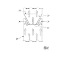
図1および図2に示すように、流体ダイオード33は、第1制限通路31内に設けられている。流体ダイオード33には、変流突部36が備えられている。変流突部36は、第1制限通路31の内周面に設けられていて、第1制限通路31内を流通する液体Lの流れを変化させる。変流突部36は、第1制限通路31の内周面から径方向の内側に向けて突出し、第1制限通路31内を、軸線O方向に流通する液体Lの流れを変化させる。   As shown in FIGS. 1 and 2, the fluid diode 33 is provided in the first restriction passage 31. The fluid diode 33 is provided with a current changing protrusion 36. The flow changing protrusion 36 is provided on the inner peripheral surface of the first restriction passage 31 and changes the flow of the liquid L flowing in the first restriction passage 31. The variable flow projection 36 projects radially inward from the inner peripheral surface of the first restriction passage 31 and changes the flow of the liquid L flowing in the first restriction passage 31 in the direction of the axis O.

変流突部36は、第1制限通路31内を流通する液体Lを、この変流突部36の表面に沿って流動させることで、この液体Lの流れを曲げさせる。変流突部36は、例えば樹脂材料などにより、液体Lの流れに受けたときに変形しない程度の剛性を具備する剛性体として、仕切り部材16と一体に形成されていて、本実施形態では、嵌合部16bに一体に形成されている。   The flow changing protrusion 36 causes the liquid L flowing in the first restriction passage 31 to flow along the surface of the current changing protrusion 36, thereby bending the flow of the liquid L. The current changing protrusion 36 is formed integrally with the partition member 16 as a rigid body having a rigidity that does not deform when receiving the flow of the liquid L, for example, by a resin material. It is formed integrally with the fitting portion 16b.

第1制限通路31および変流突部36は、軸線Oおよび変流突部36を通る縦断面視(第1制限通路の流路軸方向に沿った縦断面視)において、軸線Oに対して対称形状を呈している。第1制限通路31および変流突部36は、前記縦断面視において、軸線Oを基準として線対称となっている。変流突部36は、周方向の全周にわたって配置されていて、図示の例では、周方向の全周にわたって連続して延びている。   The first restriction passage 31 and the current-changing protrusion 36 are positioned with respect to the axis O in a vertical sectional view passing through the axis O and the current-changing protrusion 36 (a vertical sectional view along the flow path axial direction of the first restriction passage). It has a symmetrical shape. The first restriction passage 31 and the current changing protrusion 36 are symmetric with respect to the axis O in the longitudinal sectional view. The current changing protrusion 36 is disposed over the entire circumference in the circumferential direction, and in the illustrated example, continuously extends over the entire circumference in the circumferential direction.

変流突部36は、軸線O方向に延びる筒状、図示の例では円筒状に形成されている。変流突部36における軸線O方向の一端部は、第1制限通路31の内周面に連結された基端部(固定端)とされ、軸線O方向の他端部は、第1制限通路31の内周面に非連結とされた突端部(自由端)とされている。変流突部36の突端部は、軸線O方向の両側に向けて開口する通過孔37の内周縁部を形成している。図示の例では、変流突部36の突端部側の開口部の全体が通過孔37とされていて、変流突部36の突端部は、通過孔37の内周縁部の全体を構成している。   The current changing protrusion 36 is formed in a cylindrical shape extending in the direction of the axis O, and in the illustrated example, in a cylindrical shape. One end of the current changing protrusion 36 in the direction of the axis O is a base end (fixed end) connected to the inner peripheral surface of the first restriction passage 31, and the other end in the direction of the axis O is the first restriction passage. 31 is a protruding end (free end) that is not connected to the inner peripheral surface. The protruding end of the variable current protruding portion 36 forms an inner peripheral edge of a through hole 37 that opens toward both sides in the direction of the axis O. In the illustrated example, the entirety of the opening on the side of the protruding end of the current-changing projection 36 is a through hole 37, and the projecting end of the current-changing projection 36 forms the entire inner peripheral edge of the passing hole 37. ing.

変流突部36の外周面は、基端部から突端部に向かうに従い漸次、縮径していて、前記縦断面視において、軸線Oに対して直線状に傾斜している。本実施形態では、変流突部36の内周面も、基端部から突端部に向かうに従い漸次、縮径していて、変流突部36の全体が、基端部から突端部に向かうに従い漸次、縮径している。変流突部36は、一方側から他方側に向かうに従い漸次、縮径している。   The outer peripheral surface of the current changing protrusion 36 gradually decreases in diameter from the base end toward the protrusion, and is inclined linearly with respect to the axis O in the longitudinal sectional view. In the present embodiment, the inner peripheral surface of the current-changing protrusion 36 also gradually decreases in diameter from the base end toward the projecting end, and the entire current-changing protrusion 36 goes from the base end to the projecting end. The diameter gradually decreases in accordance with The diameter of the current changing protrusion 36 gradually decreases from one side to the other side.

変流突部36は、第1制限通路31内を変流空間38と通過空間39とに区画している。
変流空間38は、内部に流入する液体Lの流れを変化させる。変流突部36は、第1制限通路31の内周面との間に変流空間38を形成している。変流空間38は、変流突部36の外周面と第1制限通路31の内周面との間に形成されている。変流突部36の外周面は、変流空間38を画成する画成面であり、この画成面は、前記縦断面視において軸線Oに対して傾斜している。
The current change protrusion 36 divides the inside of the first restriction passage 31 into a current change space 38 and a passage space 39.
The flow change space 38 changes the flow of the liquid L flowing into the inside. The current-change protrusion 36 forms a current-change space 38 between itself and the inner peripheral surface of the first restriction passage 31. The current change space 38 is formed between the outer peripheral surface of the current change protrusion 36 and the inner peripheral surface of the first restriction passage 31. The outer peripheral surface of the current changing protrusion 36 is a defining surface that defines the current changing space 38, and the defining surface is inclined with respect to the axis O in the longitudinal sectional view.

変流空間38は、軸線Oと同軸の環状に形成され、他方側に向けて開口している。前記縦断面視において、変流空間38の径方向に沿った空間幅は、他方側から一方側に向かうに従い漸次、小さくなっている。変流空間38の底面は、他方側を向くとともに変流突部36の外周面と第1制限通路31の内周面とを連結している。前記縦断面視において、変流空間38の底面は、一方側に向けて凹となる凹曲面状に形成されている。   The current change space 38 is formed in an annular shape coaxial with the axis O, and opens toward the other side. In the longitudinal sectional view, the space width along the radial direction of the current changing space 38 gradually decreases from the other side to one side. The bottom surface of the current change space 38 faces the other side, and connects the outer peripheral surface of the current change protrusion 36 and the inner peripheral surface of the first restriction passage 31. In the vertical cross-sectional view, the bottom surface of the current changing space 38 is formed in a concave curved surface that is concave toward one side.

通過空間39は、内部に流入する液体Lを通過させる。通過空間39は、前記通過孔37を備えている。通過空間39は、変流突部36の内周面により形成され、変流突部36の内部の全体によって構成されている。通過空間39は、軸線Oと同軸の錐台状、図示の例では円錐台状に形成され、軸線O方向の両側に向けて開口している。通過空間39は、他方側から一方側に向かうに従い漸次、拡径している。   The passage space 39 allows the liquid L flowing inside to pass therethrough. The passage space 39 has the passage hole 37. The passage space 39 is formed by the inner peripheral surface of the current-changing protrusion 36, and is constituted by the entire inside of the current-changing protrusion 36. The passage space 39 is formed in a frustum shape coaxial with the axis O, in the illustrated example, in a truncated cone shape, and is open toward both sides in the direction of the axis O. The passage space 39 gradually expands in diameter from the other side to one side.

弾性薄膜34およびストッパ35は、流体ダイオード33に対して軸線O方向にずらされている。弾性薄膜34およびストッパ35は、流体ダイオード33に対して他方側に配置されていて、本実施形態では、本体部16aに設けられている。
弾性薄膜34は、第1制限通路31を閉塞している。弾性薄膜34は、この防振装置10に振動が入力されていない状態(以下、「未入力状態」という)で、前記縦断面視において、軸線O方向に凸となっている。弾性薄膜34は、軸線O方向に弾性変形可能に形成されている。
The elastic thin film 34 and the stopper 35 are shifted in the direction of the axis O with respect to the fluid diode 33. The elastic thin film 34 and the stopper 35 are arranged on the other side with respect to the fluid diode 33, and in this embodiment, are provided on the main body 16a.
The elastic thin film 34 closes the first restriction passage 31. The elastic thin film 34 is convex in the direction of the axis O in the longitudinal sectional view when no vibration is input to the vibration isolator 10 (hereinafter, referred to as “non-input state”). The elastic thin film 34 is formed so as to be elastically deformable in the direction of the axis O.

ストッパ35は、弾性薄膜34が他方側に向けて変形したときに、弾性薄膜34の更なる他方側に向けた変形を規制し、弾性薄膜34の他方側に向けた変形量を規制する。ストッパ35は、弾性薄膜34に対して他方側に配置されている。ストッパ35は、前記縦断面視において、第1制限通路31を、軸線Oに直交する方向に横断している。ストッパ35には、複数の流通孔35aが設けられている。流通孔35aは、ストッパ35を軸線O方向に貫通している。   The stopper 35 regulates the deformation of the elastic thin film 34 toward the other side when the elastic thin film 34 is deformed toward the other side, and regulates the amount of deformation of the elastic thin film 34 toward the other side. The stopper 35 is arranged on the other side with respect to the elastic thin film 34. The stopper 35 traverses the first restriction passage 31 in a direction perpendicular to the axis O in the longitudinal sectional view. The stopper 35 is provided with a plurality of flow holes 35a. The flow hole 35a penetrates the stopper 35 in the axis O direction.

第1制限通路31は、アイドル振動(例えば、周波数が18Hz〜30Hz、振幅が±0.5mm以下)の入力に対して液柱共振を生じさせる。一方、第2制限通路32は、シェイク振動(例えば、周波数が14Hz以下、振幅が±0.5mmより大きい)の入力に対して液柱共振を生じさせる。シェイク振動(シェイク振動)の周波数は、アイドル振動(アイドル振動)の周波数よりも低い。シェイク振動の振幅は、アイドル振動の振幅よりも大きい。   The first restriction passage 31 causes liquid column resonance with respect to an input of idle vibration (for example, a frequency of 18 Hz to 30 Hz and an amplitude of ± 0.5 mm or less). On the other hand, the second restriction passage 32 causes liquid column resonance with respect to an input of shake vibration (for example, a frequency of 14 Hz or less and an amplitude of more than ± 0.5 mm). The frequency of the shake vibration (shake vibration) is lower than the frequency of the idle vibration (idle vibration). The amplitude of the shake vibration is larger than the amplitude of the idle vibration.

なお各制限通路31、32は、例えば流路長や流路断面積などに基づいて、それぞれ対応する振動が入力されて内部を液体Lが流通するときに液柱共振が生じるように設定(チューニング)することができる。第1制限通路31の共振周波数は、アイドル振動の周波数と同等となっている。第2制限通路32の共振周波数は、シェイク振動の周波数と同等となっている。   Each of the restriction passages 31 and 32 is set (tuned) based on, for example, a flow path length or a flow path cross-sectional area so that a liquid column resonance occurs when the corresponding vibration is input and the liquid L flows through the inside. )can do. The resonance frequency of the first restriction passage 31 is equal to the frequency of the idle vibration. The resonance frequency of the second restriction passage 32 is equal to the frequency of the shake vibration.

未入力状態において、第1制限通路31の流通抵抗は、第2制限通路32の流通抵抗よりも小さくなっている。この防振装置10では、振動が入力された直後には、液体Lが、第2制限通路32よりも第1制限通路31を積極的に流通しようとする。なお、各制限通路31、32の流通抵抗は、流路長や流路断面積などに基づいて調整することができる。   In a non-input state, the flow resistance of the first restriction passage 31 is smaller than the flow resistance of the second restriction passage 32. In this vibration isolator 10, immediately after the vibration is input, the liquid L tends to flow more actively through the first restriction passage 31 than the second restriction passage 32. The flow resistance of each of the restriction passages 31 and 32 can be adjusted based on the flow path length, the flow path cross-sectional area, and the like.

次に、前記防振装置10の作用について説明する。   Next, the operation of the vibration isolator 10 will be described.

防振装置10に、振動発生部から軸線O方向の振動が入力されると、両取付け部材11、12が弾性体13を弾性変形させながら相対的に変位して主液室14の液圧が変動する。すると液体Lが、主液室14と副液室15との間を往来しようとする。このとき、主液室14内および副液室15内の液体Lは、両制限通路31、32のうち、流通抵抗が小さい第1制限通路31を流通しようとする。   When vibration in the direction of the axis O is input from the vibration generating unit to the vibration isolator 10, the mounting members 11, 12 are relatively displaced while elastically deforming the elastic body 13, and the hydraulic pressure of the main liquid chamber 14 is reduced. fluctuate. Then, the liquid L tries to move between the main liquid chamber 14 and the sub liquid chamber 15. At this time, the liquid L in the main liquid chamber 14 and the sub liquid chamber 15 tries to flow through the first restriction passage 31 having the smaller flow resistance among the two restriction passages 31 and 32.

ここで、アイドル振動の振幅はシェイク振動に比べ振幅が小さく、アイドル振動の入力時に第1制限通路31および第2制限通路32へ流入する液体Lの流速は、シェイク振動の入力時の液体Lの流速よりも小さくなる。
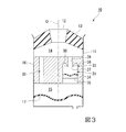
すなわち図4に示すように、軸線O方向にアイドル振動が入力されると、このアイドル振動の振幅に応じ、単位時間あたりに少量の液体Lが第1制限通路31内に流入しようとする。その結果、第1制限通路31内を流通する液体Lの流速の上昇が抑制される。
Here, the amplitude of the idle vibration is smaller than the amplitude of the shake vibration, and the flow velocity of the liquid L flowing into the first restriction passage 31 and the second restriction passage 32 at the time of inputting the idle vibration is equal to the flow velocity of the liquid L at the time of inputting the shake vibration. It becomes smaller than the flow velocity.
That is, as shown in FIG. 4, when the idle vibration is input in the direction of the axis O, a small amount of the liquid L tends to flow into the first restriction passage 31 per unit time according to the amplitude of the idle vibration. As a result, an increase in the flow velocity of the liquid L flowing in the first restriction passage 31 is suppressed.

したがって、この防振装置10のような、第1制限通路31に流体ダイオード33が設けられているような構成であっても、液体Lが流れの向きによらず第1制限通路31内を円滑に流通する。本実施形態では、液体Lが第1制限通路31内を他方側に向けて流通するとき、および一方側に向けて流通するときのいずれの場合であっても、この液体Lが、第1制限通路31のうち、流体ダイオード33が位置する部分に到達したときに、液体Lは単に通過空間39を軸線O方向に通過する。   Therefore, even in a configuration in which the fluid diode 33 is provided in the first restriction passage 31 as in the vibration isolator 10, the liquid L smoothly flows in the first restriction passage 31 regardless of the flow direction. Distribute to. In the present embodiment, regardless of whether the liquid L flows in the first restriction passage 31 toward the other side or when flowing toward the one side, the liquid L When reaching the portion of the passage 31 where the fluid diode 33 is located, the liquid L simply passes through the passage space 39 in the direction of the axis O.

なお、アイドル振動が入力された場合であって、液体Lが第1制限通路31内を流通するときには、第1制限通路31内において流体ダイオード33に到達する直前の液体Lの流速と、流体ダイオード33を通過した直後の液体Lの流速と、が等しく、または僅かに異なっていて、これらの液体Lの流速差は実質的に見受けられない。ここで、液体Lの流速差には、例えば、液体Lの流速の最大値同士の差分などを採用することができる。   When the idle vibration is input and the liquid L flows through the first restriction passage 31, the flow velocity of the liquid L immediately before reaching the fluid diode 33 in the first restriction passage 31 and the fluid diode The flow velocity of the liquid L immediately after passing through 33 is equal to or slightly different from that of the liquid L, and the flow velocity difference of these liquids L is not substantially observed. Here, as the flow velocity difference of the liquid L, for example, a difference between the maximum values of the flow velocity of the liquid L can be adopted.

ところで、第1制限通路31内を流通する液体Lは、その液圧に基づいて弾性薄膜34を弾性変形させ、液圧を、弾性薄膜34を挟んだ反対側に位置する他の液体Lに伝達させて第1制限通路31内を流通する。これにより、液体Lに、第1制限通路31を積極的に流通させることが可能になり、第1制限通路31内で共振を生じさせてアイドル振動を吸収および減衰することができる。   The liquid L flowing in the first restriction passage 31 elastically deforms the elastic thin film 34 based on the liquid pressure, and transmits the liquid pressure to another liquid L located on the opposite side of the elastic thin film 34. As a result, the gas flows through the first restriction passage 31. Thus, the first restriction passage 31 can be positively circulated in the liquid L, and resonance can be generated in the first restriction passage 31 to absorb and attenuate idle vibration.

本実施形態では、弾性薄膜34が、前記縦断面視において、軸線O方向に凸となっているので、弾性薄膜34を、この弾性薄膜34の形状に基づいて、軸線O方向に容易に変形させることができる。したがって、例えば、アイドル振動が入力されたときに、第1制限通路31を流通する液体Lの液圧によって弾性薄膜34を確実に変形させることができる。これにより、液体Lに第1制限通路31内を円滑に流通させることができる。   In the present embodiment, since the elastic thin film 34 is convex in the direction of the axis O in the longitudinal sectional view, the elastic thin film 34 is easily deformed in the direction of the axis O based on the shape of the elastic thin film 34. be able to. Therefore, for example, when idle vibration is input, the elastic thin film 34 can be reliably deformed by the liquid pressure of the liquid L flowing through the first restriction passage 31. This allows the liquid L to flow smoothly through the first restriction passage 31.

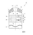
一方、図5に示すように、軸線O方向にシェイク振動が入力されると、このシェイク振動の振幅に応じて、単位時間当たりに多量の液体Lが主液室14から第1制限通路31内に流入しようとする。その結果、第1制限通路31内を流通する液体Lの流速が一定以上に高められる。   On the other hand, as shown in FIG. 5, when the shake vibration is input in the direction of the axis O, a large amount of the liquid L per unit time flows from the main liquid chamber 14 into the first restriction passage 31 in accordance with the amplitude of the shake vibration. Try to flow into As a result, the flow velocity of the liquid L flowing in the first restriction passage 31 is increased to a certain value or more.

シェイク振動が入力された場合であって、主液室14から第1制限通路31に他方側に向けて流入した液体Lが、流体ダイオード33に到達したときには、液体Lが、通過空間39内を軸線O方向に通過した後、通過孔37から流出する。その結果、このように第1制限通路31を他方側に向けて流通する液体Lの流れは、流速が一定以上に高められていても許容され、液体Lは、第1制限通路31を他方側に向けて円滑に流通して副液室15内に流入する。なお、副液室15内に液体Lが流入したり、副液室15内から液体Lが流出したりして、副液室15内の液体Lが増減しても、ダイヤフラム17が変形することで副液室15の容積も増減し、副液室15内は大気圧に保持される。   When the shake vibration is input and the liquid L flowing from the main liquid chamber 14 to the first restriction passage 31 toward the other side reaches the fluid diode 33, the liquid L flows through the passage space 39. After passing in the direction of the axis O, it flows out of the passage hole 37. As a result, the flow of the liquid L flowing through the first restriction passage 31 toward the other side is allowed even if the flow velocity is increased to a certain value or more, and the liquid L flows through the first restriction passage 31 to the other side. And flows smoothly into the sub liquid chamber 15. The diaphragm 17 may be deformed even if the liquid L in the sub liquid chamber 15 increases or decreases due to the liquid L flowing into the sub liquid chamber 15 or the liquid L flowing out of the sub liquid chamber 15. As a result, the volume of the sub liquid chamber 15 also increases and decreases, and the inside of the sub liquid chamber 15 is maintained at the atmospheric pressure.

これに対して図2および図5に示すように、副液室15から第1制限通路31に一方側に向けて流入した液体Lが、流体ダイオード33に到達したときには、この液体Lのうち、第1制限通路31内の径方向の内側を流通するものは、通過孔37を通過して通過空間39に流入し、この通過空間39を軸線O方向に通過する。一方、液体Lのうち、第1制限通路31内の径方向の外側を流通するものは、変流空間38に流入する。この液体Lは、変流突部36の表面に沿って変流突部36の突端部側に向かうことで、流れを径方向に変化させられる。なおこのとき、変流突部36は、変流空間38内に流入する液体Lの流れを、変流突部36の外周面に沿うように変化させることで、この液体Lを、周方向に延びる円周を旋回軸として旋回させること等ができる。   On the other hand, as shown in FIGS. 2 and 5, when the liquid L flowing from the auxiliary liquid chamber 15 to the first restriction passage 31 toward the one side reaches the fluid diode 33, What flows inside the first restriction passage 31 in the radial direction passes through the passage hole 37, flows into the passage space 39, and passes through the passage space 39 in the direction of the axis O. On the other hand, of the liquid L, the liquid L flowing outside in the radial direction inside the first restriction passage 31 flows into the current change space 38. This liquid L flows in the radial direction along the surface of the variable current projection 36 toward the tip end of the variable current projection 36. At this time, the current changing protrusion 36 changes the flow of the liquid L flowing into the current changing space 38 so as to follow the outer peripheral surface of the current changing protrusion 36, thereby causing the liquid L to flow in the circumferential direction. It is possible to make a revolution around the extending circumference as a pivot.

その結果、例えば、通過孔37を軸線O方向に通過しようとする液体Lと、変流突部36により流れを変化させられた液体Lと、が衝突することによるエネルギー損失などを起因として、液体Lの圧力損失が高められる。なお液体Lの圧力損失の要因としては、液体Lの粘性抵抗や、液体Lの流れを変化させ旋回流を形成することによるエネルギー損失、液体Lと変流突部36との間の摩擦によるエネルギー損失なども挙げられる。   As a result, for example, the liquid L that is going to pass through the passage hole 37 in the direction of the axis O and the liquid L whose flow has been changed by the current changing protrusion 36 collide with the liquid L due to energy loss or the like. The pressure loss of L is increased. The causes of the pressure loss of the liquid L include a viscous resistance of the liquid L, an energy loss due to a change in the flow of the liquid L to form a swirling flow, and an energy due to friction between the liquid L and the flow-changing projection 36. Loss and the like.

ここでこの防振装置10では、第1制限通路31および変流突部36が、前記縦断面視において、軸線Oに対して対称形状を呈しているので、この縦断面視において径方向の両外側に位置する部分を流通する各液体Lの流れが、変流突部36によって、軸線Oに対して対称に変化させられる。そして、このように流れを変化させられた液体Lが、通過孔37を軸線O方向に通過しようとする液体Lに対して、径方向の両外側から衝突することから、液体Lの圧力損失が効果的に高められる。   Here, in this vibration isolator 10, since the first restriction passage 31 and the current-changing projection 36 have a symmetrical shape with respect to the axis O in the longitudinal sectional view, both radial directions are seen in the longitudinal sectional view. The flow of each liquid L flowing through the portion located on the outside is changed symmetrically with respect to the axis O by the flow changing protrusion 36. The liquid L whose flow has been changed in this way collides with the liquid L that is about to pass through the passage hole 37 in the direction of the axis O from both outer sides in the radial direction. Increased effectively.

以上より、第1制限通路31を一方側に向けて流通する液体Lの流速が一定以上に高められていると液体Lの圧力損失が高められ、その結果、第1制限通路31を一方側に向けて流通する液体Lの流れが抑制される。   As described above, when the flow velocity of the liquid L flowing toward the first restriction passage 31 toward one side is increased to a certain value or more, the pressure loss of the liquid L is increased, and as a result, the first restriction passage 31 is moved to one side. The flow of the liquid L flowing toward is suppressed.

この防振装置10では、シェイク振動が入力されたときに、第1制限通路31を通して主液室14と副液室15との間を往来する液体Lのうち、第1制限通路31内を一方側に向かう液体Lの流れが流体ダイオード33によって抑制される。その結果、第1制限通路31を通して主液室14と副液室15との間を液体Lが往来するときに、一方側に向けて流通する液体Lよりも、他方側に向けて流通する液体Lが第1制限通路31内を円滑に流通し、弾性薄膜34が他方側に向けて弾性変形する。   In the vibration damping device 10, when the shake vibration is input, one of the liquids L flowing between the main liquid chamber 14 and the sub liquid chamber 15 through the first restriction passage 31 passes through the first restriction passage 31. The flow of the liquid L toward the side is suppressed by the fluid diode 33. As a result, when the liquid L flows between the main liquid chamber 14 and the sub liquid chamber 15 through the first restriction passage 31, the liquid L flowing toward one side is more liquid than the liquid L flowing toward one side. L smoothly flows in the first restriction passage 31, and the elastic thin film 34 elastically deforms toward the other side.

シェイク振動が入力され続けて液体Lが第1制限通路31を繰り返し往来すると、図5に示すように、弾性薄膜34の他方側に向けた変形量が、ストッパ35により規制されるまで徐々に大きくなり、弾性薄膜34が徐々に他方側に向けて変形し難くなる。したがって、例えば、液体Lが第1制限通路31を他方側に向けて流通しようとするときに、弾性薄膜34に、この弾性薄膜34に対して一方側に位置する液体Lの液圧が作用しても、弾性薄膜34が他方側に向けて変形し難くなり、弾性薄膜34に対して一方側に位置する液体Lの液圧が他方側に位置する液体Lに伝達され難くなる。その結果、第1制限通路31を通した液体Lの流通が阻害される。これにより、第1制限通路31を通して液体Lを流通させ難くして、第2制限通路32を通して液体Lを流通させ易くすることができる。このとき、第2制限通路32内を液体Lが流通することで第2制限通路32内で共振を生じさせ、シェイク振動を吸収および減衰することができる。
なお、シェイク振動の入力が停止されると、弾性薄膜34は、例えば弾性薄膜34の弾性復元力に基づいて、未入力状態における形状に復元変形する。
When the shake L is continuously input and the liquid L repeatedly travels through the first restriction passage 31, the amount of deformation of the elastic thin film 34 toward the other side gradually increases until it is regulated by the stopper 35, as shown in FIG. This makes it difficult for the elastic thin film 34 to gradually deform toward the other side. Therefore, for example, when the liquid L tries to flow through the first restriction passage 31 toward the other side, the liquid pressure of the liquid L located on one side of the elastic thin film 34 acts on the elastic thin film 34. However, the elastic thin film 34 is less likely to be deformed toward the other side, and the liquid pressure of the liquid L located on one side with respect to the elastic thin film 34 is less likely to be transmitted to the liquid L located on the other side. As a result, the flow of the liquid L through the first restriction passage 31 is hindered. This makes it difficult for the liquid L to flow through the first restriction passage 31 and facilitates the flow of the liquid L through the second restriction passage 32. At this time, when the liquid L flows in the second restriction passage 32, resonance occurs in the second restriction passage 32, and the shake vibration can be absorbed and attenuated.
When the input of the shake vibration is stopped, the elastic thin film 34 is restored to a shape in an uninput state based on, for example, the elastic restoring force of the elastic thin film 34.

以上説明したように、本実施形態に係る防振装置10によれば、前記従来技術のようなプランジャ部材を仕切り部材16に設けるのに代えて、第1制限通路31に流体ダイオード33および弾性薄膜34を設けることで、アイドル振動およびシェイク振動の両方を吸収および減衰させることができる。これにより、防振装置10の構造の簡素化および製造の簡便化を図ることができる。   As described above, according to the vibration isolator 10 according to the present embodiment, instead of providing the plunger member in the partition member 16 as in the related art, the fluid diode 33 and the elastic thin film are formed in the first restriction passage 31. By providing the, both idle vibration and shake vibration can be absorbed and attenuated. Thereby, simplification of the structure of the vibration isolator 10 and simplification of manufacture can be achieved.

また、第1制限通路31にストッパ35が設けられているので、ストッパ35により弾性薄膜34の変形量を精度良く規制することができる。これにより、シェイク振動が入力されたときに、第1制限通路31を通した液体Lの流通を高精度に阻害することができる。   In addition, since the stopper 35 is provided in the first restriction passage 31, the amount of deformation of the elastic thin film 34 can be accurately regulated by the stopper 35. Thereby, when the shake vibration is input, the flow of the liquid L through the first restriction passage 31 can be hindered with high accuracy.

(第2実施形態)
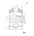
次に、本発明に係る第2実施形態の防振装置40を、図6を参照して説明する。
なお、この第2実施形態においては、第1実施形態における構成要素と同一の部分については同一の符号を付し、その説明を省略し、異なる点についてのみ説明する。
(2nd Embodiment)
Next, an anti-vibration device 40 according to a second embodiment of the present invention will be described with reference to FIG.
In the second embodiment, the same components as those in the first embodiment are denoted by the same reference numerals, and the description thereof will be omitted. Only different points will be described.

この防振装置40では、弾性薄膜34およびストッパ35を、流体ダイオード33に対して他方側に配置するのに代えて、一方側に配置している。
この防振装置40においても、第1実施形態に係る防振装置40と同様の作用効果を奏することができる。
In this vibration isolator 40, the elastic thin film 34 and the stopper 35 are arranged on one side instead of being arranged on the other side with respect to the fluid diode 33.
In the vibration isolator 40, the same operation and effect as those of the vibration isolator 40 according to the first embodiment can be obtained.

(第3実施形態)
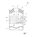
次に、本発明に係る第3実施形態の防振装置50を、図7を参照して説明する。
なお、この第3実施形態においては、第1実施形態における構成要素と同一の部分については同一の符号を付し、その説明を省略し、異なる点についてのみ説明する。
(Third embodiment)
Next, an anti-vibration device 50 according to a third embodiment of the present invention will be described with reference to FIG.
In the third embodiment, the same components as those in the first embodiment are denoted by the same reference numerals, and the description thereof will be omitted. Only different points will be described.

この防振装置50では、流体ダイオード33に、第1制限通路31を一方側に向けて流通する液体Lの流れを流速に応じて抑制させるのに代えて、第1制限通路31を他方側(第1側)に向けて流通する液体Lの流れを流速に応じて抑制させる。また流体ダイオード33に、第1制限通路31を他方側に向けて流通する液体Lの流れを流速によらず許容させるのに代えて、第1制限通路31を一方側(第2側)に向けて流通する液体Lの流れを流速によらず許容させる。さらにストッパ35に、弾性薄膜34の他方側に向けた変形量を規制させるのに代えて、弾性薄膜34の一方側に向けた変形量を規制させる。
この防振装置50における変流突部36は、第1実施形態に係る防振装置10を構成する変流突部36を、軸線O方向に反転させた形状をなす。ストッパ35は、弾性薄膜34に対して一方側に位置している。
In the vibration damping device 50, instead of suppressing the flow of the liquid L flowing through the fluid diode 33 toward the one side of the first restriction passage 31 according to the flow velocity, the first restriction passage 31 is connected to the other side ( The flow of the liquid L flowing toward the first side is suppressed according to the flow velocity. Also, instead of allowing the fluid diode 33 to allow the flow of the liquid L flowing through the first restriction passage 31 to the other side regardless of the flow velocity, the first restriction passage 31 is directed to one side (second side). To allow the flow of the liquid L flowing therethrough regardless of the flow velocity. Further, instead of restricting the amount of deformation of the elastic thin film 34 toward the other side, the stopper 35 controls the amount of deformation of the elastic thin film 34 toward one side.
The current-change protrusion 36 of the vibration-proof device 50 has a shape obtained by inverting the current-change protrusion 36 of the vibration-proof device 10 according to the first embodiment in the direction of the axis O. The stopper 35 is located on one side with respect to the elastic thin film 34.

この防振装置50では、シェイク振動が入力され、第1制限通路31内を流通する液体Lの流速が高められたときに、第1制限通路31を通して主液室14と副液室15との間を往来する液体Lのうち、第1制限通路31内を他方側に向かう液体Lの流れが流体ダイオード33によって抑制される。これにより、第1制限通路31を通して主液室14と副液室15との間を液体Lが往来するときに、他方側に向かう液体Lよりも一方側に向かう液体Lが第1制限通路31内を円滑に通過し、弾性薄膜34が一方側に向けて弾性変形させられる。   In the vibration isolator 50, when the shake vibration is input and the flow rate of the liquid L flowing in the first restriction passage 31 is increased, the main liquid chamber 14 and the sub liquid chamber 15 pass through the first restriction passage 31. The flow of the liquid L flowing toward the other side in the first restriction passage 31 among the liquids L flowing between them is suppressed by the fluid diode 33. Accordingly, when the liquid L moves between the main liquid chamber 14 and the sub liquid chamber 15 through the first restriction passage 31, the liquid L traveling to one side is more likely to travel toward the one side than the liquid L traveling to the other side. The elastic thin film 34 passes through the inside smoothly and is elastically deformed toward one side.

シェイク振動が入力され続けて液体Lが第1制限通路31を繰り返し往来すると、弾性薄膜34の一方側に向けた変形量が徐々に大きくなり、弾性薄膜34が徐々に一方側に向けて変形し難くなる。したがって、例えば、液体Lが第1制限通路31を一方側に向けて流通しようとするときに、弾性薄膜34に、この弾性薄膜34に対して他方側に位置する液体Lの液圧が作用しても、弾性薄膜34が一方側に向けて変形し難くなり、弾性薄膜34に対して他方側に位置する液体Lの液圧が一方側に位置する液体Lに伝達され難くなる。その結果、第1制限通路31を通した液体Lの流通が阻害される。これにより、第1制限通路31を通して液体Lを流通させ難くして、第2制限通路32を通して液体Lを流通させ易くすることができる。   When the shake L is continuously input and the liquid L repeatedly flows through the first restriction passage 31, the amount of deformation of the elastic thin film 34 toward one side gradually increases, and the elastic thin film 34 gradually deforms toward one side. It becomes difficult. Therefore, for example, when the liquid L is going to flow through the first restriction passage 31 toward one side, the liquid pressure of the liquid L located on the other side acts on the elastic thin film 34 with respect to the elastic thin film 34. However, the elastic thin film 34 is less likely to be deformed toward one side, and the liquid pressure of the liquid L located on the other side with respect to the elastic thin film 34 is less likely to be transmitted to the liquid L located on one side. As a result, the flow of the liquid L through the first restriction passage 31 is hindered. This makes it difficult for the liquid L to flow through the first restriction passage 31 and facilitates the flow of the liquid L through the second restriction passage 32.

(第4実施形態)
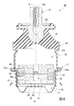
次に、本発明に係る第4実施形態の防振装置60を、図8から図12を参照して説明する。
なお、この第4実施形態においては、第1実施形態における構成要素と同一の部分については同一の符号を付し、その説明を省略し、異なる点についてのみ説明する。
(Fourth embodiment)
Next, an anti-vibration device 60 according to a fourth embodiment of the present invention will be described with reference to FIGS.
In the fourth embodiment, the same components as those in the first embodiment are denoted by the same reference numerals, the description thereof will be omitted, and only different points will be described.

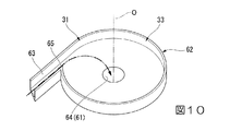
この防振装置60では、図8に示すように、流体ダイオード33を、第1制限通路31内に設けるのに代えて、流体ダイオード33に、第1制限通路31の一部を構成させている。第1制限通路31は、流体ダイオード33と、接続路61と、により構成されている。流体ダイオード33は、副液室15に直接、連通している。接続路61は、主液室14に直接、連通していて、流体ダイオード33と主液室14とを接続している。   In this vibration isolator 60, as shown in FIG. 8, instead of providing the fluid diode 33 in the first restriction passage 31, the fluid diode 33 constitutes a part of the first restriction passage 31. . The first restriction passage 31 includes a fluid diode 33 and a connection path 61. The fluid diode 33 is in direct communication with the auxiliary liquid chamber 15. The connection path 61 is in direct communication with the main liquid chamber 14 and connects the fluid diode 33 and the main liquid chamber 14.

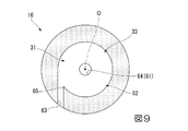
図8および図9に示すように、流体ダイオード33は、渦室62と、整流路63と、連通孔64と、を備えている。
渦室62は、主液室14および副液室15のうち、一方に整流路63を通して連通し、他方に連通孔64を通して連通している。本実施形態では、渦室62は、整流路63を通して副液室15に連通し、連通孔64を通して主液室14に連通している。渦室62は、整流路63から流入する液体Lの流速に応じて液体Lの旋回流を形成し、この液体Lを連通孔64から流出させる。渦室62は、軸線Oと同軸に配置されている。渦室62は、軸線O方向から見た平面視において、円形状に形成されている。
As shown in FIGS. 8 and 9, the fluid diode 33 includes a vortex chamber 62, a rectification path 63, and a communication hole 64.
The vortex chamber 62 communicates with one of the main liquid chamber 14 and the sub liquid chamber 15 through the rectifying path 63 and communicates with the other through the communication hole 64. In the present embodiment, the vortex chamber 62 communicates with the sub liquid chamber 15 through the rectifying path 63 and communicates with the main liquid chamber 14 through the communication hole 64. The vortex chamber 62 forms a swirling flow of the liquid L in accordance with the flow velocity of the liquid L flowing from the rectifying path 63, and causes the liquid L to flow out of the communication hole 64. The vortex chamber 62 is arranged coaxially with the axis O. The vortex chamber 62 is formed in a circular shape in plan view as viewed from the axis O direction.

整流路63は、仕切り部材16において副液室15に露出する外面から渦室62内に、周方向(渦室の周方向)に向けて開口している。整流路63は、軸線Oに直交する直交面に沿う方向に直線状に延在している。整流路63は、渦室62の内周面から、この内周面の接線方向に沿って延在している。整流路63から渦室62の内周面に開口する整流開口65を通して渦室62に流入された液体Lは、渦室62の内周面に沿って流動することで旋回する。   The rectification path 63 is open in the circumferential direction (the circumferential direction of the vortex chamber) from the outer surface of the partition member 16 exposed to the sub liquid chamber 15 into the vortex chamber 62. The rectification path 63 extends linearly in a direction along an orthogonal plane orthogonal to the axis O. The rectification path 63 extends from the inner peripheral surface of the vortex chamber 62 along a tangential direction of the inner peripheral surface. The liquid L that has flowed into the vortex chamber 62 from the rectification passage 63 through the rectification opening 65 that opens to the inner peripheral surface of the vortex chamber 62 swirls by flowing along the inner peripheral surface of the vortex chamber 62.

連通孔64は、渦室62において軸線O方向を向く端面から渦室62内に、軸線O方向(渦室の軸線方向)に向けて開口している。連通孔64は、前記平面視において円形状に形成されている。連通孔64は、軸線O(渦室の軸線)上に、図示の例では軸線Oと同軸に配置されている。つまり連通孔64の開口軸と、整流開口65の開口軸と、は互いにずらされていて、連通孔64および整流開口65は、渦室62の壁面に向けて開口している。   The communication hole 64 opens in the swirl chamber 62 from the end face of the swirl chamber 62 facing the direction of the axis O in the direction of the axis O (the axial direction of the swirl chamber). The communication hole 64 is formed in a circular shape in the plan view. The communication hole 64 is disposed coaxially with the axis O in the illustrated example on the axis O (the axis of the vortex chamber). That is, the opening axis of the communication hole 64 and the opening axis of the rectification opening 65 are shifted from each other, and the communication hole 64 and the rectification opening 65 open toward the wall surface of the vortex chamber 62.

図8に示すように、接続路61は、連通孔64から軸線O方向の一方側に向けて延びている。接続路61は、前記平面視において連通孔64と同等の形状でかつ同等の大きさに形成されている。接続路61は、軸線O方向に延在し、軸線Oと同軸に配置されている。接続路61のうち、他方側の開口端部が連通孔64を通して渦室62内に開口していて、一方側の開口端部が直接、主液室14内に開口している。   As shown in FIG. 8, the connection path 61 extends from the communication hole 64 toward one side in the direction of the axis O. The connection path 61 has the same shape and the same size as the communication hole 64 in the plan view. The connection path 61 extends in the direction of the axis O and is arranged coaxially with the axis O. The open end of the other side of the connection path 61 opens into the vortex chamber 62 through the communication hole 64, and the open end of one side opens directly into the main liquid chamber 14.

接続路61内には、前記弾性薄膜34および前記ストッパ35が設けられている。ストッパ35は、弾性薄膜34の第2側に向けた変形を規制する。
前記第1制限通路31では、例えば、接続路61の共振周波数や整流路63の共振周波数をアイドル振動の周波数と同等とすることで、アイドル振動の入力に対して液柱共振を生じさせることができる。
The elastic thin film 34 and the stopper 35 are provided in the connection path 61. The stopper 35 regulates the deformation of the elastic thin film 34 toward the second side.
In the first restriction passage 31, for example, by setting the resonance frequency of the connection path 61 and the resonance frequency of the rectification path 63 to be equal to the frequency of idle vibration, liquid column resonance can be caused with respect to the input of idle vibration. it can.

次に、前記防振装置60の作用について説明する。
この防振装置60では、流体ダイオード33が、第1制限通路31内を、副液室15から主液室14に向かう第1側に向けて流通する液体Lの流れを流速に応じて抑制する。
Next, the operation of the vibration isolator 60 will be described.
In the vibration isolator 60, the fluid diode 33 suppresses the flow of the liquid L flowing in the first restriction passage 31 from the sub liquid chamber 15 toward the first liquid chamber 14 in accordance with the flow velocity. .

すなわち、この防振装置60に軸線O方向にアイドル振動が入力され、第1制限通路31内を流通する液体Lの流速の上昇が抑制された場合において、副液室15内の液体Lが第1側に向けて第1制限通路31を流通するときには、図10に2点鎖線で示すように、整流路63から渦室62内に流入する液体Lが、渦室62内を旋回することなく流動し、連通孔64から流出される。これにより、液体Lの圧力損失の上昇を抑え、液体Lが渦室62内を円滑に流通する。   That is, when idle vibration is input to the vibration isolator 60 in the direction of the axis O and the rise in the flow velocity of the liquid L flowing in the first restriction passage 31 is suppressed, the liquid L in the sub liquid chamber 15 When flowing through the first restriction passage 31 toward the first side, the liquid L flowing into the vortex chamber 62 from the rectification passage 63 does not swirl in the vortex chamber 62 as shown by a two-dot chain line in FIG. It flows and flows out of the communication hole 64. This suppresses an increase in the pressure loss of the liquid L and allows the liquid L to smoothly flow in the vortex chamber 62.

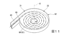
また、この防振装置60に軸線O方向にシェイク振動が入力され、第1制限通路31内を流通する液体Lの流速が一定以上に高められた場合において、副液室15内の液体Lが第1側に向けて第1制限通路31を流通するときには、液体Lは、整流路63を流通することで前記接線方向に整流された後、整流開口65から渦室62内に流入する。すると液体Lは、図11に2点鎖線で示すように、渦室62内で旋回する。すなわち液体Lが、整流開口65から渦室62に流入するときに、液体Lの流速が高められていると、この液体Lが、渦室62内を直進して渦室62の内周面(壁面)に到達し、この内周面に沿って流れを変化させられる。   Further, when the shake vibration is input to the vibration isolator 60 in the direction of the axis O and the flow velocity of the liquid L flowing in the first restriction passage 31 is increased to a certain value or more, the liquid L in the sub liquid chamber 15 When flowing through the first restriction passage 31 toward the first side, the liquid L is rectified in the tangential direction by flowing through the rectification passage 63, and then flows into the vortex chamber 62 from the rectification opening 65. Then, the liquid L swirls in the vortex chamber 62 as shown by a two-dot chain line in FIG. That is, when the flow rate of the liquid L is increased when the liquid L flows into the vortex chamber 62 from the straightening opening 65, the liquid L proceeds straight in the vortex chamber 62 and the inner peripheral surface ( (Wall surface), and the flow can be changed along the inner peripheral surface.

その結果、例えば、液体Lの粘性抵抗や、旋回流を形成することによるエネルギー損失、液体Lと渦室62の壁面との間の摩擦によるエネルギー損失などを起因として、液体Lの圧力損失が高められる。このとき、液体Lの流速の上昇に伴って渦室62内に流入する液体Lの流量が顕著に上昇すると、渦室62内に流入した液体Lにより形成された旋回流で渦室62内が満たされる。この状態で、さらに液体Lが渦室62内に流入しようとする場合、液体Lの圧力損失を大きく確保することができる。なお、渦室62内で旋回させられた液体Lは、連通孔64から流出される。
以上より、第1制限通路31を第1側に向けて流通する液体Lの流速が一定以上に高められていると液体Lの圧力損失が高められ、その結果、第1制限通路31を第1側に向けて流通する液体Lの流れが抑制される。
As a result, for example, the pressure loss of the liquid L increases due to the viscous resistance of the liquid L, energy loss due to the formation of a swirling flow, energy loss due to friction between the liquid L and the wall surface of the vortex chamber 62, and the like. Can be At this time, when the flow rate of the liquid L flowing into the vortex chamber 62 significantly increases with an increase in the flow velocity of the liquid L, the swirl flow formed by the liquid L flowing into the vortex chamber 62 causes the inside of the vortex chamber 62 to flow. It is filled. In this state, when the liquid L is to flow further into the vortex chamber 62, a large pressure loss of the liquid L can be ensured. The liquid L swirled in the vortex chamber 62 flows out of the communication hole 64.
As described above, when the flow rate of the liquid L flowing through the first restriction passage 31 toward the first side is increased to a certain value or more, the pressure loss of the liquid L is increased, and as a result, the first restriction passage 31 The flow of the liquid L flowing toward the side is suppressed.

一方、この防振装置60では、流体ダイオード33が、第1制限通路31内を、主液室14から副液室15に向かう第2側に向けて流通する液体Lの流れを流速によらず許容する。
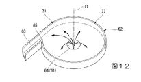
すなわち、この防振装置60に軸線O方向に振動が入力され、主液室14内の液体Lが第2側に向けて第1制限通路31を流通するときには、液体Lが、接続路61を通して連通孔64から渦室62内に流入する。渦室62内に流入した液体Lは、アイドル振動が入力されて液体Lの流速の上昇が抑制された場合、およびシェイク振動が入力される液体Lの流速が一定以上に高められた場合のいずれであっても、図12に2点鎖線で示すように、渦室62内で旋回することなく渦室62内を通過して、整流路63から流出する。その結果、液体Lの圧力損失の上昇が抑えられ、液体Lが第1制限通路31を円滑に流通する。
On the other hand, in this vibration isolator 60, the fluid diode 33 causes the flow of the liquid L flowing in the first restriction passage 31 from the main liquid chamber 14 toward the second liquid chamber 15 toward the second side regardless of the flow velocity. Allow.
That is, when vibration is input to the vibration isolator 60 in the direction of the axis O, and the liquid L in the main liquid chamber 14 flows through the first restriction passage 31 toward the second side, the liquid L passes through the connection path 61. It flows into the vortex chamber 62 from the communication hole 64. The liquid L that has flowed into the vortex chamber 62 is either when the idle vibration is input and the increase in the flow velocity of the liquid L is suppressed, or when the flow velocity of the liquid L to which the shake vibration is input is increased to a certain value or more. However, as shown by a two-dot chain line in FIG. 12, the fluid passes through the vortex chamber 62 without turning in the vortex chamber 62 and flows out of the rectification path 63. As a result, an increase in the pressure loss of the liquid L is suppressed, and the liquid L flows through the first restriction passage 31 smoothly.

以上より、アイドル振動が入力され、第1制限通路31内を流通する液体Lの流速の上昇が抑制された場合には、第1制限通路31を第1側に向けて流通する液体Lも第2側に向けて流通する液体Lも、第1制限通路31を円滑に流通する。これにより、液体Lに、第1制限通路31を積極的に流通させることが可能になり、第1制限通路31内で共振を生じさせてアイドル振動を吸収および減衰することができる。   As described above, when the idle vibration is input and the increase in the flow velocity of the liquid L flowing in the first restriction passage 31 is suppressed, the liquid L flowing in the first restriction passage 31 The liquid L flowing toward the second side also smoothly flows through the first restriction passage 31. Thus, the first restriction passage 31 can be positively circulated in the liquid L, and resonance can be generated in the first restriction passage 31 to absorb and attenuate idle vibration.

一方、シェイク振動が入力され、第1制限通路31内を流通する液体Lの流速が一定以上に高められた場合には、第1制限通路31内を第1側に向かう液体Lの流れが流体ダイオード33によって抑制されることから、第1側に向かう液体Lよりも第2側に向かう液体Lが第1制限通路31内を円滑に通過する。したがって、シェイク振動が入力されて液体Lが第1制限通路31を往来すると、弾性薄膜34が第2側に向けて弾性変形させられる。シェイク振動が入力され続けて液体Lが第1制限通路31を繰り返し往来した結果、弾性薄膜34の第2側に向けた変形量が大きくなると、第1制限通路31を通した液体Lの流通が阻害される。これにより、第1制限通路31を通して液体Lを流通させ難くして、第2制限通路32を通して液体Lを流通させ易くすることができる。このとき、第2制限通路32内を液体Lが流通することで第2制限通路32内で共振を生じさせ、シェイク振動を吸収および減衰することができる。   On the other hand, when the shake vibration is input and the flow velocity of the liquid L flowing in the first restriction passage 31 is increased to a certain value or more, the flow of the liquid L flowing toward the first side in the first restriction passage 31 becomes fluid. Since the liquid L is suppressed by the diode 33, the liquid L traveling toward the second side more smoothly passes through the first restriction passage 31 than the liquid L traveling toward the first side. Therefore, when the shake L is input and the liquid L moves through the first restriction passage 31, the elastic thin film 34 is elastically deformed toward the second side. If the amount of deformation of the elastic thin film 34 toward the second side increases as a result of the liquid L repeatedly flowing through the first restriction passage 31 while the shake vibration is continuously input, the flow of the liquid L through the first restriction passage 31 is increased. Be inhibited. This makes it difficult for the liquid L to flow through the first restriction passage 31 and facilitates the flow of the liquid L through the second restriction passage 32. At this time, when the liquid L flows in the second restriction passage 32, resonance occurs in the second restriction passage 32, and the shake vibration can be absorbed and attenuated.

なお、本発明の技術的範囲は前記実施形態に限定されるものではなく、本発明の趣旨を逸脱しない範囲において種々の変更を加えることが可能である。   Note that the technical scope of the present invention is not limited to the above embodiment, and various changes can be made without departing from the spirit of the present invention.

例えば、ストッパ35がなくてもよい。
前記実施形態では、弾性薄膜34が、前記縦断面視において、軸線O方向に凸となっているが、本発明はこれに限られない。例えば弾性薄膜34が、前記縦断面視において直線状に延びていてもよい。
For example, the stopper 35 need not be provided.
In the above embodiment, the elastic thin film 34 is convex in the direction of the axis O in the longitudinal sectional view, but the present invention is not limited to this. For example, the elastic thin film 34 may extend linearly in the longitudinal sectional view.

また前記実施形態では、第1制限通路31がアイドル振動の入力に対して共振を生じさせ、第2制限通路32がシェイク振動の入力に対して共振を生じさせたが、本発明はこれに限られない。本発明は、第1振動の入力に対して共振を生じさせる第1制限通路31と、振幅が第1振動の振幅よりも大きい第2振動の入力に対して共振を生じさせる第2制限通路32と、を備えた他の構成に適宜変更することができる。例えば、第1制限通路31が、アイドル振動よりも周波数が高い振動、高周波振動に対して共振を生じさせてもよい。   In the above-described embodiment, the first restriction passage 31 causes resonance with respect to the input of the idle vibration, and the second restriction passage 32 causes resonance with the input of the shake vibration. However, the present invention is not limited to this. I can't. The present invention provides a first restriction passage 31 that causes resonance with respect to an input of a first vibration, and a second restriction passage 32 that causes resonance with respect to an input of a second vibration whose amplitude is larger than the amplitude of the first vibration. Can be appropriately changed to another configuration including For example, the first restriction passage 31 may cause resonance with respect to vibration having a higher frequency than idle vibration or high-frequency vibration.

また流体ダイオード33は、前記実施形態に示した構成に限られない。流体ダイオード33は、第1制限通路31内を第1側に向けて流通する液体Lの流れを流速に応じて抑制する他の構成に適宜変更可能であり、流量依存性および方向依存性がある他の形態に変更してもよい。   Further, the fluid diode 33 is not limited to the configuration shown in the above embodiment. The fluid diode 33 can be appropriately changed to another configuration that suppresses the flow of the liquid L flowing in the first restriction passage 31 toward the first side in accordance with the flow velocity, and has a flow rate dependency and a direction dependency. You may change to another form.

また前記実施形態では、仕切り部材16が、第1取付け部材11内の液室を、弾性体13を壁面の一部に有する主液室14および副液室15に仕切るが、本発明はこれに限られない。例えば、前記ダイヤフラムを設けるのに代えて、弾性体を軸線方向に一対設けて、副液室を設けるのに代えて、弾性体を壁面の一部に有する受圧液室を設けてもよい。
つまり仕切り部材が、液体が封入される第1取付け部材内の液室を、第1液室および第2液室に仕切り、第1液室および第2液室の両液室のうちの少なくとも1つが、弾性体を壁面の一部に有する他の構成に適宜変更してもよい。
In the above-described embodiment, the partition member 16 partitions the liquid chamber in the first mounting member 11 into the main liquid chamber 14 and the sub liquid chamber 15 having the elastic body 13 on a part of the wall surface. Not limited. For example, instead of providing the diaphragm, a pair of elastic bodies may be provided in the axial direction, and instead of providing the auxiliary liquid chamber, a pressure receiving liquid chamber having the elastic body in a part of the wall surface may be provided.
That is, the partitioning member partitions the liquid chamber in the first mounting member in which the liquid is sealed into a first liquid chamber and a second liquid chamber, and at least one of the first liquid chamber and the second liquid chamber. On the other hand, another configuration having an elastic body on a part of the wall surface may be appropriately changed.

また前記実施形態では、エンジンを第2取付け部材12に接続し、第1取付け部材11を車体に接続しているが、逆に接続するように構成してもよい。   In the above-described embodiment, the engine is connected to the second mounting member 12 and the first mounting member 11 is connected to the vehicle body.

さらに、本発明に係る防振装置10は、車両のエンジンマウントに限定されるものではなく、エンジンマウント以外に適用することも可能である。例えば、建設機械に搭載された発電機のマウントにも適用することも可能であり、或いは、工場等に設置される機械のマウントにも適用することも可能である。   Further, the anti-vibration device 10 according to the present invention is not limited to the engine mount of the vehicle, but can be applied to other than the engine mount. For example, the present invention can be applied to a mount of a generator mounted on a construction machine, or can be applied to a mount of a machine installed in a factory or the like.

その他、本発明の趣旨に逸脱しない範囲で、前記実施形態における構成要素を周知の構成要素に置き換えることは適宜可能であり、また、前記した変形例を適宜組み合わせてもよい。   In addition, without departing from the spirit of the present invention, it is possible to appropriately replace the components in the above-described embodiment with known components, and the above-described modifications may be appropriately combined.

10 防振装置
11 第1取付け部材
12 第2取付け部材
13 弾性体
14 主液室(第1液室)
15 副液室(第2液室)
16 仕切り部材
31 第1制限通路
32 第2制限通路
33 流体ダイオード
34 弾性薄膜
35 ストッパ
L 液体
Reference Signs List 10 Anti-vibration device 11 First mounting member 12 Second mounting member 13 Elastic body 14 Main liquid chamber (first liquid chamber)
15 Secondary liquid chamber (second liquid chamber)
16 Partition member 31 First restriction passage 32 Second restriction passage 33 Fluid diode 34 Elastic thin film 35 Stopper L Liquid

Claims (3)

振動発生部および振動受部のうちの一方に連結される筒状の第1取付け部材、および他方に連結される第2取付け部材と、
これらの両取付け部材を連結する弾性体と、
液体が封入される前記第1取付け部材内の液室を、第1液室および第2液室に仕切る仕切り部材と、を備え、
前記第1液室および前記第2液室のうちの少なくとも一方は、前記弾性体を壁面の一部に有し、
前記仕切り部材には、前記第1液室と前記第2液室とを連通する制限通路が形成され、
前記制限通路として、
第1振動の入力に対して共振を生じさせる第1制限通路と、
振幅が前記第1振動の振幅よりも大きい第2振動の入力に対して共振を生じさせる第2制限通路と、を備え、
前記第1制限通路には、前記仕切り部材に固定され、前記第1制限通路内を、前記第1液室および前記第2液室のうちの一方から他方に向かう第1側に向けて流通して整流された液体の流れを流速に応じて抑制する流体ダイオードと、前記第1制限通路を閉塞する弾性薄膜と、が設けられ、
前記第2振動が入力されたときに、液体が前記第1液室と前記第2液室との間で前記第1制限通路を通して前記弾性薄膜を変形させながら流通可能であることを特徴とする防振装置。
A first cylindrical mounting member connected to one of the vibration generating unit and the vibration receiving unit, and a second mounting member connected to the other;
An elastic body connecting these two mounting members,
A partition member for partitioning a liquid chamber in the first mounting member in which a liquid is sealed into a first liquid chamber and a second liquid chamber;
At least one of the first liquid chamber and the second liquid chamber has the elastic body on a part of a wall surface,
In the partition member, a restriction passage communicating the first liquid chamber and the second liquid chamber is formed,
As the restriction passage,
A first restriction passage that causes resonance with respect to the input of the first vibration;
A second restriction passage that causes resonance with respect to an input of a second vibration whose amplitude is larger than the amplitude of the first vibration,
The first restriction passage is fixed to the partition member and circulates through the first restriction passage from the one of the first liquid chamber and the second liquid chamber toward the first side toward the other. A fluid diode that suppresses the flow of the rectified liquid according to the flow velocity, and an elastic thin film that closes the first restriction passage,
When the second vibration is input, the liquid can flow between the first liquid chamber and the second liquid chamber while deforming the elastic thin film through the first restriction passage. Anti-vibration device.
前記第1制限通路には、前記弾性薄膜が、前記第1側の反対側である第2側に向けて変形したときに、前記弾性薄膜の更なる前記第2側に向けた変形を規制するストッパが設けられていることを特徴とする請求項1記載の防振装置。   The first restriction passage restricts further deformation of the elastic thin film toward the second side when the elastic thin film is deformed toward the second side opposite to the first side. The vibration isolator according to claim 1, further comprising a stopper. 前記弾性薄膜は、前記第1制限通路の流路軸方向に沿った縦断面視において、前記流路軸方向に凸となっていることを特徴とする請求項1または2に記載の防振装置。   The anti-vibration device according to claim 1, wherein the elastic thin film is convex in the axial direction of the flow passage in a vertical cross-sectional view along the axial direction of the flow passage of the first restriction passage. .
JP2014125196A 2014-06-18 2014-06-18 Anti-vibration device Active JP6654792B2 (en)

Priority Applications (1)

Application Number Priority Date Filing Date Title
JP2014125196A JP6654792B2 (en) 2014-06-18 2014-06-18 Anti-vibration device

Applications Claiming Priority (1)

Application Number Priority Date Filing Date Title
JP2014125196A JP6654792B2 (en) 2014-06-18 2014-06-18 Anti-vibration device

Publications (2)

Publication Number Publication Date
JP2016003726A JP2016003726A (en) 2016-01-12
JP6654792B2 true JP6654792B2 (en) 2020-02-26

Family

ID=55223150

Family Applications (1)

Application Number Title Priority Date Filing Date
JP2014125196A Active JP6654792B2 (en) 2014-06-18 2014-06-18 Anti-vibration device

Country Status (1)

Country Link
JP (1) JP6654792B2 (en)

Family Cites Families (6)

* Cited by examiner, † Cited by third party
Publication number Priority date Publication date Assignee Title
JPH0754131B2 (en) * 1984-09-07 1995-06-07 株式会社ブリヂストン Anti-vibration device
JPS61156749U (en) * 1985-03-20 1986-09-29
JPH01229132A (en) * 1988-03-09 1989-09-12 Tokai Rubber Ind Ltd Fluid sealed type mount device
JP4378249B2 (en) * 2004-09-02 2009-12-02 倉敷化工株式会社 Liquid filled anti-vibration mount device
JP4740776B2 (en) * 2006-01-20 2011-08-03 東洋ゴム工業株式会社 Liquid-filled vibration isolator
JP2010025149A (en) * 2008-07-15 2010-02-04 Toyota Motor Corp Liquid filled vibration damper

Also Published As

Publication number Publication date
JP2016003726A (en) 2016-01-12

Similar Documents

Publication Publication Date Title
JP6196682B2 (en) Vibration isolator
JP6245646B2 (en) Vibration isolator
JP6300407B2 (en) Vibration isolator
JP6300406B2 (en) Vibration isolator
US9772003B2 (en) Vibration damping device
JP6196681B2 (en) Vibration isolator
JP6265562B2 (en) Vibration isolator
US10047819B2 (en) Vibration-damping device
JP2015200386A (en) Vibration-proof device
EP3006771B1 (en) Vibration damping device
JP6355242B2 (en) Vibration isolator
US10578187B2 (en) Vibration isolation device
JPWO2018198442A1 (en) Anti-vibration device
JP6654792B2 (en) Anti-vibration device
JP6155122B2 (en) Vibration isolator
JP7346189B2 (en) Vibration isolator
JP2016114146A (en) Vibration control device

Legal Events

Date Code Title Description
A621 Written request for application examination

Free format text: JAPANESE INTERMEDIATE CODE: A621

Effective date: 20170510

A977 Report on retrieval

Free format text: JAPANESE INTERMEDIATE CODE: A971007

Effective date: 20180309

A131 Notification of reasons for refusal

Free format text: JAPANESE INTERMEDIATE CODE: A131

Effective date: 20180320

A521 Request for written amendment filed

Free format text: JAPANESE INTERMEDIATE CODE: A523

Effective date: 20180511

A131 Notification of reasons for refusal

Free format text: JAPANESE INTERMEDIATE CODE: A131

Effective date: 20180911

RD03 Notification of appointment of power of attorney

Free format text: JAPANESE INTERMEDIATE CODE: A7423

Effective date: 20181019

A521 Request for written amendment filed

Free format text: JAPANESE INTERMEDIATE CODE: A523

Effective date: 20181107

A02 Decision of refusal

Free format text: JAPANESE INTERMEDIATE CODE: A02

Effective date: 20190312

A521 Request for written amendment filed

Free format text: JAPANESE INTERMEDIATE CODE: A523

Effective date: 20190606

A911 Transfer to examiner for re-examination before appeal (zenchi)

Free format text: JAPANESE INTERMEDIATE CODE: A911

Effective date: 20190614

A912 Re-examination (zenchi) completed and case transferred to appeal board

Free format text: JAPANESE INTERMEDIATE CODE: A912

Effective date: 20190816

A61 First payment of annual fees (during grant procedure)

Free format text: JAPANESE INTERMEDIATE CODE: A61

Effective date: 20200131

R150 Certificate of patent or registration of utility model

Ref document number: 6654792

Country of ref document: JP

Free format text: JAPANESE INTERMEDIATE CODE: R150

S111 Request for change of ownership or part of ownership

Free format text: JAPANESE INTERMEDIATE CODE: R313111

R350 Written notification of registration of transfer

Free format text: JAPANESE INTERMEDIATE CODE: R350

R250 Receipt of annual fees

Free format text: JAPANESE INTERMEDIATE CODE: R250