JP6653838B2 - Wireless receiver - Google Patents
Wireless receiver Download PDFInfo
- Publication number
- JP6653838B2 JP6653838B2 JP2015246900A JP2015246900A JP6653838B2 JP 6653838 B2 JP6653838 B2 JP 6653838B2 JP 2015246900 A JP2015246900 A JP 2015246900A JP 2015246900 A JP2015246900 A JP 2015246900A JP 6653838 B2 JP6653838 B2 JP 6653838B2
- Authority
- JP
- Japan
- Prior art keywords
- error rate
- value
- wireless receiver
- envelope
- correction
- Prior art date
- Legal status (The legal status is an assumption and is not a legal conclusion. Google has not performed a legal analysis and makes no representation as to the accuracy of the status listed.)
- Active
Links
- 238000012937 correction Methods 0.000 claims description 32
- 238000005259 measurement Methods 0.000 claims description 6
- 238000001514 detection method Methods 0.000 description 10
- 238000004891 communication Methods 0.000 description 7
- 238000000034 method Methods 0.000 description 7
- 238000012545 processing Methods 0.000 description 6
- 230000035945 sensitivity Effects 0.000 description 4
- 238000010586 diagram Methods 0.000 description 2
- 230000003321 amplification Effects 0.000 description 1
- 230000005540 biological transmission Effects 0.000 description 1
- 238000004519 manufacturing process Methods 0.000 description 1
- 238000003199 nucleic acid amplification method Methods 0.000 description 1
- 230000008054 signal transmission Effects 0.000 description 1
Images

Classifications
-
- H—ELECTRICITY
- H04—ELECTRIC COMMUNICATION TECHNIQUE
- H04B—TRANSMISSION
- H04B1/00—Details of transmission systems, not covered by a single one of groups H04B3/00 - H04B13/00; Details of transmission systems not characterised by the medium used for transmission
- H04B1/06—Receivers
- H04B1/10—Means associated with receiver for limiting or suppressing noise or interference
- H04B1/1027—Means associated with receiver for limiting or suppressing noise or interference assessing signal quality or detecting noise/interference for the received signal
- H04B1/1036—Means associated with receiver for limiting or suppressing noise or interference assessing signal quality or detecting noise/interference for the received signal with automatic suppression of narrow band noise or interference, e.g. by using tuneable notch filters
-
- H—ELECTRICITY
- H04—ELECTRIC COMMUNICATION TECHNIQUE
- H04B—TRANSMISSION
- H04B1/00—Details of transmission systems, not covered by a single one of groups H04B3/00 - H04B13/00; Details of transmission systems not characterised by the medium used for transmission
-
- H—ELECTRICITY
- H04—ELECTRIC COMMUNICATION TECHNIQUE
- H04B—TRANSMISSION
- H04B1/00—Details of transmission systems, not covered by a single one of groups H04B3/00 - H04B13/00; Details of transmission systems not characterised by the medium used for transmission
- H04B1/06—Receivers
- H04B1/10—Means associated with receiver for limiting or suppressing noise or interference
- H04B1/12—Neutralising, balancing, or compensation arrangements
- H04B1/123—Neutralising, balancing, or compensation arrangements using adaptive balancing or compensation means
-
- H—ELECTRICITY
- H04—ELECTRIC COMMUNICATION TECHNIQUE
- H04B—TRANSMISSION
- H04B1/00—Details of transmission systems, not covered by a single one of groups H04B3/00 - H04B13/00; Details of transmission systems not characterised by the medium used for transmission
- H04B1/06—Receivers
- H04B1/16—Circuits
-
- H—ELECTRICITY
- H04—ELECTRIC COMMUNICATION TECHNIQUE
- H04B—TRANSMISSION
- H04B1/00—Details of transmission systems, not covered by a single one of groups H04B3/00 - H04B13/00; Details of transmission systems not characterised by the medium used for transmission
- H04B1/69—Spread spectrum techniques
- H04B1/7163—Spread spectrum techniques using impulse radio
- H04B1/71637—Receiver aspects
-
- H—ELECTRICITY
- H04—ELECTRIC COMMUNICATION TECHNIQUE
- H04B—TRANSMISSION
- H04B7/00—Radio transmission systems, i.e. using radiation field
- H04B7/02—Diversity systems; Multi-antenna system, i.e. transmission or reception using multiple antennas
- H04B7/04—Diversity systems; Multi-antenna system, i.e. transmission or reception using multiple antennas using two or more spaced independent antennas
- H04B7/08—Diversity systems; Multi-antenna system, i.e. transmission or reception using multiple antennas using two or more spaced independent antennas at the receiving station
-
- H—ELECTRICITY
- H04—ELECTRIC COMMUNICATION TECHNIQUE
- H04L—TRANSMISSION OF DIGITAL INFORMATION, e.g. TELEGRAPHIC COMMUNICATION
- H04L1/00—Arrangements for detecting or preventing errors in the information received
- H04L1/20—Arrangements for detecting or preventing errors in the information received using signal quality detector
- H04L1/203—Details of error rate determination, e.g. BER, FER or WER
-
- H—ELECTRICITY
- H04—ELECTRIC COMMUNICATION TECHNIQUE
- H04L—TRANSMISSION OF DIGITAL INFORMATION, e.g. TELEGRAPHIC COMMUNICATION
- H04L25/00—Baseband systems
- H04L25/02—Details ; arrangements for supplying electrical power along data transmission lines
- H04L25/06—Dc level restoring means; Bias distortion correction ; Decision circuits providing symbol by symbol detection
- H04L25/061—Dc level restoring means; Bias distortion correction ; Decision circuits providing symbol by symbol detection providing hard decisions only; arrangements for tracking or suppressing unwanted low frequency components, e.g. removal of dc offset
- H04L25/063—Setting decision thresholds using feedback techniques only
-
- H—ELECTRICITY
- H04—ELECTRIC COMMUNICATION TECHNIQUE
- H04L—TRANSMISSION OF DIGITAL INFORMATION, e.g. TELEGRAPHIC COMMUNICATION
- H04L27/00—Modulated-carrier systems
- H04L27/02—Amplitude-modulated carrier systems, e.g. using on-off keying; Single sideband or vestigial sideband modulation
- H04L27/06—Demodulator circuits; Receiver circuits
Description
本発明は、インパルス型超広帯域(UWB:Ultra Wide Band)を用いつつ受信感度を向上することのできる無線受信機に関するものである。 The present invention relates to a radio receiver capable of improving reception sensitivity while using an impulse type ultra wide band (UWB).
近年注目されている無線通信技術として、時間幅が極めて小さいパルスを用いて通信を行うインパルスUWBを用いる技術がある(特許文献1参照)。 As a wireless communication technique that has attracted attention in recent years, there is a technique using an impulse UWB that performs communication using a pulse having a very small time width (see Patent Document 1).
インパルスUWBでは、1ナノ秒以下の非常に短い時間幅のパルス信号を利用し、そのパルス信号の時間軸上の位置や振幅又は位相等を変化させることで情報の伝送が行われる。 In the impulse UWB, a pulse signal having a very short time width of 1 nanosecond or less is used, and information is transmitted by changing the position, amplitude, phase, or the like of the pulse signal on the time axis.
UWB信号が占有する周波数帯域は500MHzから数GHz以上と非常に広くなるが、1ナノ秒の非常に短い時間幅のパルス信号を用いることから、高いデータレートの信号伝送や高精度の測距が実現され得る。 The frequency band occupied by the UWB signal is very wide from 500 MHz to several GHz or more, but since a pulse signal with a very short time width of 1 nanosecond is used, signal transmission at a high data rate and high-precision distance measurement are possible. Can be realized.
また、インパルスUWBを用いる無線通信方式では、送受信機の構成をシンプルなものにすることができ、製造コストを低く抑えることができるとともに、消費電力も低く抑えることが可能となる。 In the wireless communication system using the impulse UWB, the configuration of the transceiver can be simplified, the manufacturing cost can be reduced, and the power consumption can be reduced.
こうしたインパルスUWBを用いる場合には、パルスのオンオフ制御に基づくOOK(On−Off Keying)変調や、パルスの位置に基づくPPM(Pulse Position Modulation)変調を基本処理とし、受信機ではいずれも電力検波を行う必要がある。 When such an impulse UWB is used, OOK (On-Off Keying) modulation based on pulse on / off control and PPM (Pulse Position Modulation) modulation based on the position of the pulse are the basic processes, and the power detection is performed by the receiver. There is a need to do.
そして、受信機側では受信したデータの復調プロセスにおいてパルスの有無の判断処理を行う必要があり、ノイズや受信波形の変動の影響を排除し、目的波のみを正確に捉えるかが重要となる。 Then, on the receiver side, it is necessary to perform a process of judging the presence or absence of a pulse in the demodulation process of the received data, and it is important to eliminate the influence of noise and fluctuation of the received waveform and to accurately capture only the target wave.
具体的には、受信機が受信する受信波には目的波以外のノイズが含まれ、また空中伝搬経路によっては受信波高値が大幅に変動する。 Specifically, the received wave received by the receiver includes noise other than the target wave, and the received wave peak value greatly varies depending on the air propagation path.
そこで、ノイズを誤って信号のパルスと判断しないように、信号のパルスとノイズとを区別する閾値を高く設定することが考えられる。 Therefore, it is conceivable to set a high threshold value for discriminating between signal pulses and noise so that noise is not erroneously determined to be signal pulses.
しかし、閾値を高く設定してしまうと、目的波が弱いものである場合には受信機が信号のパルスを検出することができず、受信感度の低下を招いてしまう。 However, if the threshold value is set high, the receiver cannot detect the signal pulse when the target wave is weak, which causes a decrease in the receiving sensitivity.
そこで、本発明は、上述した問題点に鑑みて案出されたものであり、UWBを用いつつ受信感度を向上することのできる無線受信機を提供することを目的とする。 Then, this invention was devised in view of the above-mentioned problem, and an object of this invention is to provide a radio receiver which can improve receiving sensitivity using UWB.
第1発明に係る無線受信機は、インパルスUWBを用いる無線受信機であって、前記インパルスUWBを受信する受信アンテナと、受信した前記インパルスUWBを増幅するとともに前記インパルスUWBの包絡線の検波を行う受信部と、前記包絡線の最大値を検出する最大ピーク検出部と、前記包絡線の最小値を検出する最小ピーク検出部と、前記包絡線から初期閾値を用いて信号データを得るコンパレータと、前記信号データのエラー率を測定するベースバンド部と、前記エラー率に基づき補正値を算出するMPUと、前記最大値、前記最小値及び前記補正値に基づき補正閾値を算出し、前記コンパレータに送信する演算部と、を備え、前記コンパレータは前記演算部から送信された前記補正閾値に基づき前記包絡線から前記信号データを得る、ことを特徴とする。 A wireless receiver according to a first aspect of the present invention is a wireless receiver using an impulse UWB, and a receiving antenna for receiving the impulse UWB, amplifying the received impulse UWB, and detecting an envelope of the impulse UWB. A receiving unit, a maximum peak detecting unit that detects a maximum value of the envelope, a minimum peak detecting unit that detects a minimum value of the envelope, and a comparator that obtains signal data using an initial threshold value from the envelope, A baseband unit that measures an error rate of the signal data, an MPU that calculates a correction value based on the error rate, and a correction threshold that is calculated based on the maximum value, the minimum value, and the correction value, and transmits the correction threshold value to the comparator. And the comparator is configured to calculate the signal data from the envelope based on the correction threshold value transmitted from the arithmetic unit. Obtained, characterized in that.
第2発明に係る無線受信機は、第1発明において、前記演算部は前記最大値X、前記最小値Y及び前記補正値Zに基づき式(1)の演算を行い、補正閾値Vtを算出し、前記補正閾値Vtを前記コンパレータに送信することを特徴とする請求項1記載の無線受信機。
In a wireless receiver according to a second aspect of the present invention, in the first aspect, the calculation unit performs a calculation of Expression (1) based on the maximum value X, the minimum value Y, and the correction value Z to calculate a correction threshold value Vt. The wireless receiver according to

第3発明に係る無線受信機は、第1発明又は第2発明において、前記エラー率としてビットエラーレートが用いられ、前記MPUは前記ビットエラーレートに基づき前記補正値を算出することを特徴とする。 A wireless receiver according to a third invention is characterized in that, in the first invention or the second invention, a bit error rate is used as the error rate, and the MPU calculates the correction value based on the bit error rate. .
第4発明に係る無線受信機は、第1発明又は第2発明において、前記エラー率としてパケットエラーレートが用いられ、前記MPUは前記パケットエラーレートに基づき前記補正値を算出することを特徴とする。 A wireless receiver according to a fourth invention is characterized in that, in the first invention or the second invention, a packet error rate is used as the error rate, and the MPU calculates the correction value based on the packet error rate. .
第5発明に係る無線受信機は、第1発明乃至第4発明の何れか1つにおいて、複数の前記受信部と、複数の前記受信部からの前記包絡線を加算する加算器と、を備えることを特徴とする。 A wireless receiver according to a fifth aspect is the radio receiver according to any one of the first to fourth aspects, further comprising: a plurality of the receiving units; and an adder that adds the envelopes from the plurality of the receiving units. It is characterized by the following.
第6発明に係る無線受信機は、第1発明乃至第5発明の何れか1つにおいて、前記ベースバンド部による前記エラー率の測定は所定期間毎に行われることを特徴とする。 A wireless receiver according to a sixth aspect is based on any one of the first to fifth aspects, wherein the measurement of the error rate by the baseband unit is performed at predetermined intervals.
上述した構成からなる本発明によれば、インパルスUWBを用いつつ受信感度を向上することのできる無線受信機を提供することが可能となる。 According to the present invention having the above-described configuration, it is possible to provide a wireless receiver that can improve reception sensitivity while using impulse UWB.
以下、本発明の実施形態に係る無線受信機及び無線通信システムについて説明する。 Hereinafter, a wireless receiver and a wireless communication system according to an embodiment of the present invention will be described.
<無線受信機>
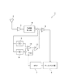
図1は、本発明の実施形態に係る無線受信機を示すシステム構成ブロック図である。本実施形態に係る無線受信機1は、アンテナ2と、低ノイズ増幅器(LNA)3と、包絡線検出器4と、コンパレータ5と、ベースバンド部6と、MPU(Micro Processing Unit)7と、最大ピーク検出部8と、最小ピーク検出部9と、2段の演算部10、11と、を備えて構成されている。
<Wireless receiver>
FIG. 1 is a system configuration block diagram illustrating a wireless receiver according to an embodiment of the present invention. The
アンテナ2は、送信機から発せられたインパルスUWBを受信するためのアンテナである。
The
LNA3は、アンテナ2を介して受信したインパルスUWBについて、増幅過程で重畳される雑音を抑えつつ、UWB信号の増幅を行う。
The LNA 3 amplifies the UWB signal of the impulse UWB received via the
包絡線検出器4は、LNA3から出力された信号の包絡線に基づき、この信号に対する電圧の振幅を検出する。なお、便宜のためアンテナ2、LNA3及び包絡線検出器4をまとめて受信部と定義する。
The envelope detector 4 detects the amplitude of the voltage for this signal based on the envelope of the signal output from the LNA 3. For convenience, the
コンパレータ5は、包絡線検出器4により検出された電圧の信号強度を、所定の閾値と比較し、閾値以上の信号強度を目的波信号あり、閾値未満の信号強度を目的波信号無しとして判定する。
The
ベースバンド部6は、受信データを復調し、コンパレータ5による検出結果のうち目的波信号有りの状態を1、目的波信号無しの状態を0としてデジタル信号の生成を行い、出力データとして図示しない他の装置による処理のために提供する。データの送受信のための変復調は任意の方式で行うことができ、例えばパルス密度変復調を用いることができる。
The baseband unit 6 demodulates the received data and generates a digital signal by setting the state of the presence of the target signal to 1 and the state of no target signal to 0 in the detection result of the
また、ベースバンド部6は、受信データのエラー率の測定を行う。測定されるエラー率としてはビットエラーレートやパケットエラーレート等、任意のものを採用することができる。ベースバンド部によるエラー率の測定は任意のタイミングで行うことができ、例えば所定の複数のパケット毎に行われる。 Further, the baseband unit 6 measures the error rate of the received data. An arbitrary error rate such as a bit error rate or a packet error rate can be adopted as the measured error rate. The measurement of the error rate by the baseband unit can be performed at an arbitrary timing, for example, for each of a plurality of predetermined packets.
MPU7は、無線受信機1の構成全体の制御を行う制御機構である。
The MPU 7 is a control mechanism that controls the entire configuration of the
最大ピーク検出部8は、所定期間にわたっての包絡線検出器4により検出された包絡線の最大値を検出する。この所定期間の包絡線の最大値をXとする。 The maximum peak detector 8 detects the maximum value of the envelope detected by the envelope detector 4 over a predetermined period. Let X be the maximum value of the envelope for this predetermined period.
最小ピーク検出部9は、所定期間にわたっての包絡線検出器4により検出された包絡線の最小値を検出する。この所定期間の包絡線の最小値をYとする。
The
演算部10は、(X−Y)/Zの演算を行う。ここでZは補正値であり、MPUにより算出される、受信信号のエラー率が最小となる値である。
The
演算部11は、演算部10による演算結果に対してYの加算を行う。
The
すなわち、演算部10、11により、以下の式(1)に示す演算が行われ、補正閾値Vtが算出される。
That is, the
そして算出された補正閾値Vtはコンパレータ5へと送信され、コンパレータ5の以後の処理に供される。
Then, the calculated correction threshold value Vt is transmitted to the
図2は、無線受信機による検出波形を示すグラフである。図2にVtとX、Yの関係が示されている。コンパレータ5により、包絡線が閾値Vt以上の部分について目的波信号あり、閾値Vt未満の部分について目的波信号無し、と判定される。
FIG. 2 is a graph showing a waveform detected by the wireless receiver. FIG. 2 shows the relationship between Vt and X and Y. The
次に、上述した構成を有する無線受信機1による動作について詳細に説明する。
Next, the operation of the
まず、無線受信機1のアンテナ2が、外部の無線送信器から送信されたインパルスUWBの受信を行い、受信したインパルスUWBをLNA3へと送信する。
First, the
次に、LNA3が、アンテナ2により受信されたインパルスUWBに混入されている雑音を抑えつつ、インパルスUWBの増幅を行う。こうすることで、微弱な信号であり雑音による影響を受けやすいインパルスUWBについて、雑音による影響を抑制し、信号の検出を精度よく行うことができる。そしてLNA3は、増幅したインパルスUWBを包絡線検出器4へと送信する。
Next, the LNA 3 amplifies the impulse UWB while suppressing noise mixed in the impulse UWB received by the
次に、包絡線検出器4が、LNA3から出力された信号の包絡線に基づき、この信号に対する電圧の振幅を検出する。そして包絡線検出器4は、検出した電圧の振幅をコンパレータ5、最大ピーク検出部8及び最小ピーク検出部9へと送信する。
Next, the envelope detector 4 detects the amplitude of the voltage for the signal based on the envelope of the signal output from the LNA 3. Then, the envelope detector 4 transmits the detected voltage amplitude to the
次に、コンパレータ5は、包絡線検出器4により検出された電圧の信号強度を、所定の閾値と比較し、閾値以上の信号強度を目的波信号あり、閾値未満の信号強度を目的波信号無しとして判定し、デジタルデータの生成を行う。
Next, the
次に、ベースバンド部6は、受信データを復調し、コンパレータ5による検出結果のうち信号有りの状態を1、信号無しの状態を0としてデジタル信号の生成を行い、出力データとして図示しない他の装置による処理のために提供する。また、受信データのエラー率の測定をベースバンド部6で行う。
Next, the baseband unit 6 demodulates the received data, generates a digital signal by setting the signal presence state to 1 and the signal absence state to 0 among the detection results of the
エラー率の測定は、例えば受信データに対して施されているデータの修正率や誤り検出の結果に基づき行われるが、この態様に限らず他の態様によりエラー率の測定が行われてもよい。 The measurement of the error rate is performed based on, for example, the correction rate of the data applied to the received data and the result of the error detection. However, the measurement of the error rate is not limited to this mode and may be performed in another mode. .
ベースバンド部6により測定されたエラー率は、ベースバンド部6からMPU7へと送信される。 The error rate measured by the baseband unit 6 is transmitted from the baseband unit 6 to the MPU 7.
次に、MPU7が、ベースバンド部6により得られたエラー率に基づき、受信信号のエラー率が最少となるZを算出する。算出された補正値Zは、MPU7から演算部10へと送信される。
Next, the MPU 7 calculates Z that minimizes the error rate of the received signal based on the error rate obtained by the baseband unit 6. The calculated correction value Z is transmitted from the MPU 7 to the
一方、最大ピーク検出部8は、包絡線検出器4から送信された電圧の振幅の最大値Xを検出し、演算部10へと送信する。
On the other hand, the maximum peak detection unit 8 detects the maximum value X of the amplitude of the voltage transmitted from the envelope detector 4 and transmits the maximum value X to the
また、最小ピーク検出部9は、包絡線検出器4から送信された電圧の振幅の最小値Yを検出し、演算部10及び演算部11へと送信する。
Further, the
演算部10は、最大ピーク検出部8から送信された最大値Xと、最小ピーク検出部9から送信された最小値Y、そしてMPU7から送信された補正値Zを用いて、(X−Y)/Zの演算を行う。演算部10による演算結果は、演算部10から演算部11へと送信される。
The
演算部11は、演算部10による(X−Y)/Zの演算結果と、最小ピーク検出部9により検出された最小値Yを用いて、上述した式(1)の演算を行い、補正閾値Vtの算出を行う。
The
こうして算出された補正閾値Vtは、演算部11からコンパレータ5へと送信される。補正閾値Vtを受信したコンパレータ5は、以後の動作をこの補正閾値Vtを用いて行う。
The correction threshold value Vt calculated in this way is transmitted from the
そして、この補正閾値Vtを用いて行われたコンパレータ5による信号の有無の判定結果はベースバンド部6へと送信され、以後無線受信機1は、上述した処理と同様に再度のエラー率の測定から新たな補正閾値Vtの算出を行う。
Then, the result of the determination of the presence or absence of the signal by the
本実施形態に係る無線受信機1によると、通信状況に応じて閾値の調節を行うことで弱い受信波の検出が可能となり、その結果インパルスUWBを用いた場合でも通信距離を伸ばすことが可能となる。
According to the
なお、上述した実施形態に係る無線受信機1はそれぞれ単一の受信部、すなわちアンテナ2、LNA3及び包絡線検出器4を1つずつ備えて構成されていた。しかし、本発明においてはこれに限らず、受信部が複数設けられている態様であってもよい。
The
この場合、複数の受信部から出力される包絡線を加算する加算器が、受信部とコンパレータ5の間に設けられる。
In this case, an adder that adds the envelopes output from the plurality of receiving units is provided between the receiving unit and the
このように加算器を設けることで、複数の受信部により受信したインパルスUWBの電力が理論上受信部の数に応じて倍増する。これによりインパルスUWBの受信電力を高めることができ、従来よりも長距離の無線通信を実現することができる。 By providing the adder in this way, the power of the impulse UWB received by the plurality of receiving units theoretically doubles according to the number of receiving units. As a result, the reception power of the impulse UWB can be increased, and wireless communication over a longer distance than before can be realized.
1 無線受信機
2 アンテナ
3 低ノイズ増幅器(LNA)
4 包絡線検出器
5 コンパレータ
6 ベースバンド部
7 MPU(Micro Processing Unit)
8 最大ピーク検出部
9 最小ピーク検出部
10、11 演算部
1
4
8
Claims (6)
前記インパルスUWBを受信する受信アンテナと、
受信した前記インパルスUWBを増幅するとともに前記インパルスUWBの包絡線の検波を行う受信部と、
前記包絡線の最大値を検出する最大ピーク検出部と、
前記包絡線の最小値を検出する最小ピーク検出部と、
前記包絡線から初期閾値を用いて信号データを得るコンパレータと、
前記信号データのエラー率を測定するベースバンド部と、
前記エラー率に基づき補正値を算出するMPUと、
前記最大値、前記最小値及び前記補正値に基づき補正閾値を算出し、前記コンパレータに送信する演算部と、
を備え、
前記コンパレータは前記演算部から送信された前記補正閾値に基づき前記包絡線から前記信号データを得る、
ことを特徴とする無線受信機。 A radio receiver using an impulse UWB,
A receiving antenna for receiving the impulse UWB;
A receiving unit that amplifies the received impulse UWB and detects an envelope of the impulse UWB;
A maximum peak detector that detects a maximum value of the envelope,
A minimum peak detector for detecting a minimum value of the envelope,
A comparator for obtaining signal data from the envelope using an initial threshold value;
A baseband unit for measuring an error rate of the signal data,
An MPU that calculates a correction value based on the error rate;
An arithmetic unit that calculates a correction threshold based on the maximum value, the minimum value, and the correction value, and transmits the correction threshold to the comparator.
With
The comparator obtains the signal data from the envelope based on the correction threshold transmitted from the arithmetic unit,
A wireless receiver, characterized in that:
複数の前記受信部からの前記包絡線を加算する加算器と、
を備えることを特徴とする請求項1乃至4の何れか1項記載の無線受信機。 A plurality of the receiving units;
An adder for adding the envelopes from the plurality of receiving units,
The wireless receiver according to any one of claims 1 to 4, further comprising:
Priority Applications (4)
| Application Number | Priority Date | Filing Date | Title |
|---|---|---|---|
| JP2015246900A JP6653838B2 (en) | 2015-12-18 | 2015-12-18 | Wireless receiver |
| PCT/JP2016/086921 WO2017104615A1 (en) | 2015-12-18 | 2016-12-12 | Wireless receiver |
| US16/061,963 US10277263B2 (en) | 2015-12-18 | 2016-12-12 | Radio receiver |
| EP16875592.4A EP3393050B1 (en) | 2015-12-18 | 2016-12-12 | Wireless receiver |
Applications Claiming Priority (1)
| Application Number | Priority Date | Filing Date | Title |
|---|---|---|---|
| JP2015246900A JP6653838B2 (en) | 2015-12-18 | 2015-12-18 | Wireless receiver |
Publications (2)
| Publication Number | Publication Date |
|---|---|
| JP2017112553A JP2017112553A (en) | 2017-06-22 |
| JP6653838B2 true JP6653838B2 (en) | 2020-02-26 |
Family
ID=59056645
Family Applications (1)
| Application Number | Title | Priority Date | Filing Date |
|---|---|---|---|
| JP2015246900A Active JP6653838B2 (en) | 2015-12-18 | 2015-12-18 | Wireless receiver |
Country Status (4)
| Country | Link |
|---|---|
| US (1) | US10277263B2 (en) |
| EP (1) | EP3393050B1 (en) |
| JP (1) | JP6653838B2 (en) |
| WO (1) | WO2017104615A1 (en) |
Family Cites Families (7)
| Publication number | Priority date | Publication date | Assignee | Title |
|---|---|---|---|---|
| JPH10163877A (en) | 1996-11-28 | 1998-06-19 | Sony Corp | Threshold control circuit of multi-valued comparator for demodulation circuit |
| US7209523B1 (en) * | 1997-05-16 | 2007-04-24 | Multispectral Solutions, Inc. | Ultra-wideband receiver and transmitter |
| JP2000078211A (en) * | 1998-09-03 | 2000-03-14 | Sony Corp | Information demodulator, information demodulating method and providing medium |
| US7539271B2 (en) * | 2002-08-16 | 2009-05-26 | Wisair Ltd. | System and method for multi-band ultra-wide band signal generators |
| KR100818246B1 (en) * | 2007-04-18 | 2008-04-02 | 삼성전자주식회사 | Communication apparatus using chaotic signal and method thereof |
| KR101141050B1 (en) * | 2009-12-15 | 2012-05-03 | 한국전기연구원 | APPARATUS AND METHOD FOR DETECTING AN IMPULSE SIGNAL and impulse train |
| JP6256739B2 (en) | 2013-09-17 | 2018-01-10 | 国立研究開発法人情報通信研究機構 | Wireless transmitter, wireless receiver, wireless communication system, and wireless communication method |
-
2015
- 2015-12-18 JP JP2015246900A patent/JP6653838B2/en active Active
-
2016
- 2016-12-12 US US16/061,963 patent/US10277263B2/en active Active
- 2016-12-12 EP EP16875592.4A patent/EP3393050B1/en active Active
- 2016-12-12 WO PCT/JP2016/086921 patent/WO2017104615A1/en active Application Filing
Also Published As
| Publication number | Publication date |
|---|---|
| EP3393050A1 (en) | 2018-10-24 |
| EP3393050A4 (en) | 2019-08-21 |
| JP2017112553A (en) | 2017-06-22 |
| US20180367176A1 (en) | 2018-12-20 |
| EP3393050B1 (en) | 2022-05-04 |
| US10277263B2 (en) | 2019-04-30 |
| WO2017104615A1 (en) | 2017-06-22 |
Similar Documents
| Publication | Publication Date | Title |
|---|---|---|
| JP5438196B2 (en) | Method of determining line of sight (LOS) distance between telecommunications devices | |
| KR101520775B1 (en) | Two-way ranging messaging scheme | |
| US8698572B2 (en) | Delay line calibration | |
| JP6225041B2 (en) | Receiver | |
| JP4821375B2 (en) | Transmitting apparatus and communication system | |
| KR102162491B1 (en) | Method and apparatus of detecting interference signal for low power envelope detector | |
| KR20130042500A (en) | System and method for transmitting and receiving signal with quasi-periodic pulse sequence | |
| US20130016621A1 (en) | Device and method for restricting transmission output in a portable terminal | |
| WO2011149497A1 (en) | Two-way ranging messaging scheme | |
| US8731108B2 (en) | Communication system for recognizing type of noise source | |
| US20080043649A1 (en) | Reliable Packet Detection In A Wireless Receiver When Packets Contain A Known Repetitive Sequence | |
| MX2020008714A (en) | Collision detection method. | |
| WO2011014769A1 (en) | System and method for transmission and detection of frame including bursts of pulses | |
| US8787440B2 (en) | Determination of receive data values | |
| EP2201714B1 (en) | Interference mitigation for impulse-based communication | |
| JP2005086364A (en) | Agc control method of radio communication mobile station | |
| JP6653838B2 (en) | Wireless receiver | |
| JP2009273053A (en) | Transmitting apparatus, receiving apparatus and communication system | |
| US8254595B2 (en) | System and method of companding an input signal of an energy detecting receiver | |
| JP4937805B2 (en) | RADIO COMMUNICATION DEVICE AND DISTANCE MEASURING METHOD IN RADIO COMMUNICATION DEVICE | |
| KR102434972B1 (en) | Apparatus and method for performing pulse decoding | |
| JP4667055B2 (en) | Apparatus and method for correcting DC offset in radio receiver | |
| KR20110071755A (en) | Packet detection scheme using cross correlation and input signal power in mb-ofdm uwb system | |
| JP2011029963A (en) | Receiver | |
| JP5887433B2 (en) | Receive stage and receive method |
Legal Events
| Date | Code | Title | Description |
|---|---|---|---|
| A621 | Written request for application examination |
Free format text: JAPANESE INTERMEDIATE CODE: A621 Effective date: 20181108 |
|
| A521 | Request for written amendment filed |
Free format text: JAPANESE INTERMEDIATE CODE: A821 Effective date: 20181108 |
|
| A131 | Notification of reasons for refusal |
Free format text: JAPANESE INTERMEDIATE CODE: A131 Effective date: 20190910 |
|
| TRDD | Decision of grant or rejection written | ||
| A01 | Written decision to grant a patent or to grant a registration (utility model) |
Free format text: JAPANESE INTERMEDIATE CODE: A01 Effective date: 20191203 |
|
| A61 | First payment of annual fees (during grant procedure) |
Free format text: JAPANESE INTERMEDIATE CODE: A61 Effective date: 20191219 |
|
| R150 | Certificate of patent or registration of utility model |
Ref document number: 6653838 Country of ref document: JP Free format text: JAPANESE INTERMEDIATE CODE: R150 |
|
| R250 | Receipt of annual fees |
Free format text: JAPANESE INTERMEDIATE CODE: R250 |
|
| R250 | Receipt of annual fees |
Free format text: JAPANESE INTERMEDIATE CODE: R250 |