JP6652915B2 - Mobile recess detection system and method - Google Patents
Mobile recess detection system and method Download PDFInfo
- Publication number
- JP6652915B2 JP6652915B2 JP2016518404A JP2016518404A JP6652915B2 JP 6652915 B2 JP6652915 B2 JP 6652915B2 JP 2016518404 A JP2016518404 A JP 2016518404A JP 2016518404 A JP2016518404 A JP 2016518404A JP 6652915 B2 JP6652915 B2 JP 6652915B2
- Authority
- JP
- Japan
- Prior art keywords
- image
- processing device
- characteristic
- extracted
- acquired
- Prior art date
- Legal status (The legal status is an assumption and is not a legal conclusion. Google has not performed a legal analysis and makes no representation as to the accuracy of the status listed.)
- Active
Links
- 238000000034 method Methods 0.000 title claims description 41
- 238000001514 detection method Methods 0.000 title 1
- 238000012545 processing Methods 0.000 claims description 89
- 230000005856 abnormality Effects 0.000 claims description 34
- 239000000463 material Substances 0.000 claims description 17
- 230000007613 environmental effect Effects 0.000 claims description 13
- 230000015556 catabolic process Effects 0.000 claims description 12
- 238000006731 degradation reaction Methods 0.000 claims description 12
- 238000004891 communication Methods 0.000 claims description 11
- 230000002596 correlated effect Effects 0.000 claims description 11
- 230000003068 static effect Effects 0.000 claims description 11
- 230000008859 change Effects 0.000 claims description 6
- 239000000284 extract Substances 0.000 claims description 6
- 230000006866 deterioration Effects 0.000 claims description 5
- 238000012546 transfer Methods 0.000 claims description 3
- 230000005540 biological transmission Effects 0.000 claims 1
- 238000004422 calculation algorithm Methods 0.000 description 10
- 230000002093 peripheral effect Effects 0.000 description 9
- 238000012423 maintenance Methods 0.000 description 7
- 238000004458 analytical method Methods 0.000 description 5
- 230000008569 process Effects 0.000 description 4
- 230000008439 repair process Effects 0.000 description 4
- 238000004364 calculation method Methods 0.000 description 3
- 238000003709 image segmentation Methods 0.000 description 3
- 238000010295 mobile communication Methods 0.000 description 3
- 238000012986 modification Methods 0.000 description 3
- 230000004048 modification Effects 0.000 description 3
- 230000003449 preventive effect Effects 0.000 description 3
- 238000005516 engineering process Methods 0.000 description 2
- 238000000605 extraction Methods 0.000 description 2
- 238000001914 filtration Methods 0.000 description 2
- 238000003384 imaging method Methods 0.000 description 2
- 239000003973 paint Substances 0.000 description 2
- 230000004044 response Effects 0.000 description 2
- 238000007493 shaping process Methods 0.000 description 2
- 230000001133 acceleration Effects 0.000 description 1
- 238000013528 artificial neural network Methods 0.000 description 1
- 239000010426 asphalt Substances 0.000 description 1
- 230000001351 cycling effect Effects 0.000 description 1
- 230000002542 deteriorative effect Effects 0.000 description 1
- 238000013213 extrapolation Methods 0.000 description 1
- 230000006870 function Effects 0.000 description 1
- 230000005484 gravity Effects 0.000 description 1
- 238000009499 grossing Methods 0.000 description 1
- 238000007373 indentation Methods 0.000 description 1
- 238000007726 management method Methods 0.000 description 1
- 238000013507 mapping Methods 0.000 description 1
- 238000005259 measurement Methods 0.000 description 1
- 230000003287 optical effect Effects 0.000 description 1
- 238000003909 pattern recognition Methods 0.000 description 1
- 238000005211 surface analysis Methods 0.000 description 1
- 238000012876 topography Methods 0.000 description 1
Images


Classifications
-
- B—PERFORMING OPERATIONS; TRANSPORTING
- B60—VEHICLES IN GENERAL
- B60W—CONJOINT CONTROL OF VEHICLE SUB-UNITS OF DIFFERENT TYPE OR DIFFERENT FUNCTION; CONTROL SYSTEMS SPECIALLY ADAPTED FOR HYBRID VEHICLES; ROAD VEHICLE DRIVE CONTROL SYSTEMS FOR PURPOSES NOT RELATED TO THE CONTROL OF A PARTICULAR SUB-UNIT
- B60W40/00—Estimation or calculation of non-directly measurable driving parameters for road vehicle drive control systems not related to the control of a particular sub unit, e.g. by using mathematical models
- B60W40/02—Estimation or calculation of non-directly measurable driving parameters for road vehicle drive control systems not related to the control of a particular sub unit, e.g. by using mathematical models related to ambient conditions
- B60W40/06—Road conditions
-
- G—PHYSICS
- G06—COMPUTING; CALCULATING OR COUNTING
- G06T—IMAGE DATA PROCESSING OR GENERATION, IN GENERAL
- G06T7/00—Image analysis
- G06T7/0002—Inspection of images, e.g. flaw detection
- G06T7/0004—Industrial image inspection
-
- G—PHYSICS
- G01—MEASURING; TESTING
- G01N—INVESTIGATING OR ANALYSING MATERIALS BY DETERMINING THEIR CHEMICAL OR PHYSICAL PROPERTIES
- G01N21/00—Investigating or analysing materials by the use of optical means, i.e. using sub-millimetre waves, infrared, visible or ultraviolet light
-
- G—PHYSICS
- G01—MEASURING; TESTING
- G01N—INVESTIGATING OR ANALYSING MATERIALS BY DETERMINING THEIR CHEMICAL OR PHYSICAL PROPERTIES
- G01N2223/00—Investigating materials by wave or particle radiation
- G01N2223/60—Specific applications or type of materials
- G01N2223/614—Specific applications or type of materials road surface
-
- G—PHYSICS
- G06—COMPUTING; CALCULATING OR COUNTING
- G06T—IMAGE DATA PROCESSING OR GENERATION, IN GENERAL
- G06T2207/00—Indexing scheme for image analysis or image enhancement
- G06T2207/10—Image acquisition modality
- G06T2207/10016—Video; Image sequence
-
- G—PHYSICS
- G06—COMPUTING; CALCULATING OR COUNTING
- G06T—IMAGE DATA PROCESSING OR GENERATION, IN GENERAL
- G06T2207/00—Indexing scheme for image analysis or image enhancement
- G06T2207/20—Special algorithmic details
- G06T2207/20048—Transform domain processing
- G06T2207/20064—Wavelet transform [DWT]
-
- G—PHYSICS
- G06—COMPUTING; CALCULATING OR COUNTING
- G06T—IMAGE DATA PROCESSING OR GENERATION, IN GENERAL
- G06T2207/00—Indexing scheme for image analysis or image enhancement
- G06T2207/30—Subject of image; Context of image processing
- G06T2207/30108—Industrial image inspection
- G06T2207/30132—Masonry; Concrete
-
- G—PHYSICS
- G06—COMPUTING; CALCULATING OR COUNTING
- G06T—IMAGE DATA PROCESSING OR GENERATION, IN GENERAL
- G06T2207/00—Indexing scheme for image analysis or image enhancement
- G06T2207/30—Subject of image; Context of image processing
- G06T2207/30181—Earth observation
- G06T2207/30184—Infrastructure
-
- G—PHYSICS
- G06—COMPUTING; CALCULATING OR COUNTING
- G06T—IMAGE DATA PROCESSING OR GENERATION, IN GENERAL
- G06T2207/00—Indexing scheme for image analysis or image enhancement
- G06T2207/30—Subject of image; Context of image processing
- G06T2207/30248—Vehicle exterior or interior
- G06T2207/30252—Vehicle exterior; Vicinity of vehicle
- G06T2207/30256—Lane; Road marking
Description
本発明の開示は、表面異常を検出するように構成された面撮像システム等の面撮像システムに関する。 The present disclosure relates to surface imaging systems, such as surface imaging systems configured to detect surface abnormalities.
道路保守プログラムは、道路舗装及び舗装面の品質及び安全性を維持することに関連付けられる。道路を調査して損傷している部分又は区域がないか否かを決定する多くのシステム及びプログラムが考案されている。これらのシステムは、面解析を実行するためのレーザ、カメラ、及びレーダーのような技術を使用することができる。 Road maintenance programs are associated with maintaining the quality and safety of road pavements and paved surfaces. Many systems and programs have been devised for examining roads to determine if there are any damaged parts or areas. These systems can use technologies such as lasers, cameras, and radar to perform surface analysis.
例えば、公知のシステムでは、地中探知レーダーが、道路舗装及び道路の表面寿命に影響を与える可能性がある条件を評価して残りの使用寿命を評価するためにマッピング技術と共に使用される。このシステムは、GPS受信機と共にラップトップコンピュータを使用して領域マップ上の道路位置を追跡し、以前の使用寿命の格付けと、道路のセグメントに関する履歴データと、道路面に行われた以前の修復とに関するデータを収集する。 For example, in known systems, underground radars are used in conjunction with mapping techniques to assess conditions that can affect road pavement and road surface life and to assess the remaining useful life. The system uses a laptop computer with a GPS receiver to track the location of the road on the area map, ranks the previous service life, historical data on segments of the road, and any previous repairs made on the road surface. And collect data about.
別の公知のシステムでは、自動道路アナライザを使用して表面の凸凹、車の跡、及び亀裂に関する情報を収集する。データは、舗装保存及び復旧修理の両方に対するターゲットを識別するプロセッサに給送される。 Another known system uses an automatic road analyzer to collect information about surface irregularities, car tracks, and cracks. The data is fed to a processor that identifies targets for both pavement conservation and repair.
更に別の公知のシステムでは、自動化損傷調査を使用して舗装条件を評価し、適切な予防的保守処置を定める際の亀裂密度を計算する。全ての処置タイプ、ストレスレベル、及び交通量を表す舗装の様々な区画は、保存対策の効果を可視的に評価するためにモニタされる。 Yet another known system uses automated damage surveys to evaluate pavement conditions and calculate crack densities in determining appropriate preventive maintenance actions. Various sections of the pavement, representing all treatment types, stress levels, and traffic volumes, are monitored to visually assess the effectiveness of conservation measures.
これらのシステム及びプログラムの実施は、労力及び時間集約的である可能性がある。予算の縮小及び衰退するインフラストラクチャーに起因して、道路保守部門は、少ない人材で保守を実行するという問題に直面する可能性がある。道路保守システム又はプログラムを維持する費用は、使用する保守車両及び機器の費用も伴うものであり、これが予算の負担になり、システムをその最大機能で使用することを妨げる可能性がある。 Implementation of these systems and programs can be labor and time intensive. Due to shrinking budgets and declining infrastructure, road maintenance departments may face the problem of performing maintenance with fewer personnel. The cost of maintaining a road maintenance system or program also entails the cost of maintenance vehicles and equipment used, which can be costly and prevent the system from being used at its full capacity.
劣化の傾向にある表面を解析するための例示のシステムを開示し、システムは、表面の少なくとも1つの画像を取得するように構成されたセンサと、タイムスタンプ及び地理座標データを取得した各画像に関連付けて表面異常が少なくとも1つの取得した画像に現れた時間を識別するように構成され、かつ、表面異常を示す取得した画像の少なくとも1つを選択するように構成された第1の処理デバイスと、少なくとも1つの選択した画像において識別された表面異常の少なくとも1つの特性を抽出し、抽出した特性を表すデータをデータベースに格納するように構成され、かつ、共通地理座標に相関付けられた複数の画像から抽出した少なくとも1つの特性に基づいて、経時的に表面劣化を解析することによって表面の傾向データを生成するように構成された第2の処理デバイスとを含む。 Disclosed is an example system for analyzing a surface that is prone to deteriorating, the system including a sensor configured to acquire at least one image of the surface and a timestamp and geographic coordinate data for each acquired image. A first processing device associated with the first processing device configured to identify a time at which the surface abnormality appeared in the at least one acquired image, and configured to select at least one of the acquired images indicative of the surface abnormality; A plurality of at least one characteristic of the surface anomaly identified in the at least one selected image, configured to store data representing the extracted characteristic in a database, and correlated to the common geographic coordinates. Generating surface trend data by analyzing surface degradation over time based on at least one characteristic extracted from the image And a second processing device configured to.
表面劣化を解析するための例示的な装置を開示し、装置は、表面の画像を取得するように構成されたセンサと、取得した画像を地理座標に相関付け、取得した画像の少なくとも1つにおいて識別された表面異常の少なくとも1つの特性を抽出し、かつ共通地理座標に相関付けられた画像において識別された表面異常の少なくとも1つの特性の経時的な変化に基づいて傾向データを生成するように構成された処理デバイスとを含む。 Disclosed is an exemplary apparatus for analyzing surface degradation, the apparatus comprising: a sensor configured to acquire an image of a surface; correlating the acquired image to geographic coordinates; and at least one of the acquired images. Extracting at least one characteristic of the identified surface anomaly and generating trend data based on a change over time of the at least one characteristic of the identified surface anomaly in the image correlated to the common geographic coordinates; And a configured processing device.
表面劣化を識別する例示的な方法を開示し、本方法は、センサから表面の画像を取得する段階と、取得した画像を地理座標データに関連付ける段階と、取得した画像を処理して表面の異常を識別し、かつ表面異常の少なくとも1つの特性を抽出する段階と、共通地理座標に相関付けられた画像から抽出した少なくとも1つの特性の経時的な変化を解析することにより、選択した異常に関する傾向データを生成する段階とを含む。 Disclosed is an exemplary method of identifying surface degradation, the method comprising: obtaining an image of a surface from a sensor; associating the obtained image with geographic coordinate data; and processing the obtained image to provide a surface abnormality. And extracting at least one property of the surface anomaly, and analyzing the change over time of the at least one property extracted from the image correlated to the common geographic coordinates, to determine a trend with respect to the selected anomaly. Generating data.
例示的な非一時的コンピュータ可読媒体を開示し、コンピュータ可読媒体には、プロセッサとの通信可能接点に置かれた時に、プロセッサが、表面の少なくとも1つの画像を取得する段階と、少なくとも1つの取得した画像を地理座標データに関連付ける段階と、少なくとも1つの取得した画像を処理して表面の異常を識別し、かつ少なくとも1つの取得した画像において識別された表面異常の少なくとも1つの特性を抽出する段階と、共通地理座標に相関付けられた複数の画像から抽出した少なくとも1つの特性の基づいて経時的に表面劣化を解析することにより、表面異常に関する傾向データを生成する段階とを含む表面劣化を測定する方法を実行するようにプログラミングコードが記録されている。 An exemplary non-transitory computer-readable medium is disclosed, wherein the computer-readable medium, when placed at a communicable contact with the processor, obtains at least one image of the surface; Associating the identified image with the geographic coordinate data and processing the at least one acquired image to identify a surface abnormality and extracting at least one characteristic of the identified surface abnormality in the at least one acquired image. Analyzing the surface degradation over time based on at least one characteristic extracted from the plurality of images correlated to the common geographic coordinates to generate trend data relating to the surface anomaly. Programming code is recorded to perform the method.
以下に、例示の実施形態により及び添付図面を参照して本発明の開示をより詳しく説明する。 Hereinafter, the disclosure of the present invention will be described in more detail by way of exemplary embodiments and with reference to the accompanying drawings.
本発明の開示の例示の実施形態は、道路の表面のような面を連続的にモニタすることができる画像の自動化された現地収集を提供し、表面劣化又は異常のような道路の特徴が発生した時に修復することができるように取得したデータを解析することができるシステムに関する。本明細書で開示する例示のシステムは、小型で廉価とすることができ、車両への複雑な又は労力を要する修正なしに車両内又は車両上に装着することができる。 An exemplary embodiment of the present disclosure provides an automated on-site collection of images that can continuously monitor a surface, such as the surface of a road, where road features such as surface degradation or abnormalities occur. The present invention relates to a system that can analyze acquired data so that it can be repaired when the system is restored. The exemplary systems disclosed herein can be small and inexpensive and can be mounted in or on vehicles without complex or labor intensive modifications to the vehicle.
本明細書に説明する例示のシステムは、データ主導の予防的計画を提供することによって自治体の車両及び人件費を低減することができ、それによって既存のサービス車両及び経路を使用して修復経路及びスケジュール及び正確な道路条件の報告を最適化することができる。詳細なサービス崩壊解析の提供、表面の調査を取得する場合の時間間隔の低減、及び予防保守の有効性の増加により、材料費も低減することができる。本発明の開示の例示の実施形態は、独立したシステムとして廉価に維持及び使用することができ、又は既存の表面及び/又は舗装道路管理システムに統合することができるシステムを提供する。 The example systems described herein can reduce municipal fleet and labor costs by providing data-driven preventive planning, thereby using existing service vehicles and routes to rehabilitate and rebuild. Schedule and accurate road condition reporting can be optimized. Material costs can also be reduced by providing a detailed service disruption analysis, reducing the time interval when acquiring surface surveys, and increasing the effectiveness of preventive maintenance. Exemplary embodiments of the present disclosure provide a system that can be inexpensively maintained and used as a stand-alone system, or can be integrated with existing surface and / or pavement management systems.
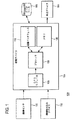
図1は、本発明の開示の例示の実施形態による表面を解析するためのシステムを示している。本発明の開示の関連で説明するように、表面とは、環境条件及び/又は車両による使用ために摩耗又は劣化を受ける面又は平面を含むことができる。本発明の開示の関連では、車両は、エンジンを備えた又はエンジンなしの運搬の任意のモードとすることができ、車、オートバイ、自転車、トラック、又は望ましい位置で又は望ましい距離から表面の画像を撮影することができるいずれかの他の適切な運搬モードのような1つ又はそれよりも多くの車軸を有するものとすることができる。表面は、コンクリート、アスファルト、これらの任意の組合せ、又は必要に応じて道路面を形成するのに適する他の材料のような材料を含むことができる。 FIG. 1 shows a system for analyzing a surface according to an exemplary embodiment of the present disclosure. As described in the context of the present disclosure, a surface can include a surface or plane that is subject to wear or deterioration for use by environmental conditions and / or vehicles. In the context of the present disclosure, a vehicle can be in any mode of transport, with or without an engine, and can provide images of a car, motorcycle, bicycle, truck, or surface at a desired location or from a desired distance. It may have one or more axles, such as any other suitable transport mode that can be photographed. The surface may include materials such as concrete, asphalt, any combination thereof, or other materials suitable for forming a road surface as needed.
図1に示すように、システム100は、表面の少なくとも1つの画像を取得するように構成されたセンサ102を含む。画像センサ102は、カメラ又は加速度計のうちの少なくとも一方を含むことができる。例えば、例示の実施形態において、画像センサ102は、1/4インチレンズで少なくとも720p/60高精細HDビデオ撮影のフレーム速度を有する5メガピクセルカメラを含むことができる。このカメラは、1秒当たり30フレームで720px1080pHDビデオを提供することができる。このカメラは、1/4μmx1/4μmピクセルサイズのビデオ及びスナップショット作動の両方に対応するように構成することができる。例示の実施形態において、画像センサ102は、車両上の画像センサが表面異常に遭遇した時に引き起こされる振動による加速度を測定するように構成された少なくとも1つの加速度計を含むことができる。
As shown in FIG. 1,
システム100は、タイムスタンプ及び地理座標データを取得した各画像に関連付けて表面異常が少なくとも1つの取得した画像に現れた時間を識別し、表面異常を示す取得した画像の少なくとも1つを選択するように構成された処理デバイス104を含む。表面異常は、限定されないが、亀裂、溝、くぼみ(例えば、道路孔)又は、ゆがみ、カップ、リッジ、及び/又は表面材料の摩耗又は劣化によって引き起こされたいずれかの他の表面特徴、又は表面の修正又は処理(例えば、塗料の塗布又は他の望ましいか又は望ましくない塗装)のいずれかの形態から生じたものを含む経時的な変化を受けた表面の任意の指定された特徴とすることができる。
The
処理デバイス104は、小型でコンパクトなサイズになるように構成することができ、車両上又は車両内に装着することができる。例示の実施形態において、処理デバイス104は、プリント回路基板(PCB)に装着されたモジュール、回路、及びプロセッサのような複数の構成要素を含むことができる。処理デバイス104は、全地球測位システム(GPS)の任意の数の衛星に接続して位置(例えば、地理座標)及び時間情報を提供する全地球測位システム(GPS)モジュール106を含むことができる。GPSから取得した位置及び時間情報は、取得した画像に関連付けられる。処理デバイス104は、取得した画像から少なくとも1つの特徴を抽出し、抽出した特徴が表面異常を識別するか否かを決定し、この決定に基づいて取得した画像の少なくとも1つを選択するように構成されたプロセッサ108を含むことができる。
The
例えば、例示の実施形態において、取得した画像は、ビデオを含有し、プロセッサ108は、そのビデオで画像の各フレームを解析してフレームのいずれかが異常を含む可能性を決定する。異常を含有すると決定されたフレームが選択される。第1の処理デバイス104によって実行されるこの画像処理のレベルは、プロセッサ及びメモリのサイズ及び速度によって決定することができる。
For example, in the exemplary embodiment, the acquired image contains a video, and the
例えば、別の例示の実施形態において、画像のセットの各フレームを変換してグレースケール画像を取得することができる。フィルタをグレースケール画像に適用してノイズを低減及び/又は取り除くことができる。ノイズが取り除かれた後に、更に画像を処理し、例えば、その全画像又は一部分をテンプレート画像と比較して異常が存在するか否かを決定することができる。異常を含有すると決定された画像が選択され、更に解析するために別のプロセッサ又は処理デバイスに通信される。 For example, in another exemplary embodiment, each frame of the set of images can be transformed to obtain a grayscale image. Filters can be applied to the grayscale image to reduce and / or eliminate noise. After the noise has been removed, the image can be further processed, for example, comparing the entire image or a portion thereof to the template image to determine if an anomaly exists. The image determined to contain the anomaly is selected and communicated to another processor or processing device for further analysis.
更に別の例示の実施形態において、第1の処理デバイス104は、いくつかの画像セグメント化アルゴリズムのいずれかを画像に適用することができる。例えば、閾値アルゴリズムを各画像に実行してバイナリ画像を生成することができる。閾値アルゴリズムは、ヒストグラム成形方法、クラスター化ベースの方法、エントロピーベースの方法、オブジェクト−属性ベースの方法、空間的な方法、ローカルな方法、又は望ましいいずれかの他の適切な閾値技術のいずれかを含むことができる。三角アルゴリズムは、例示的なヒストグラム成形方法を使用して画像に適用することができる。画像を濾過して閾値をヒストグラムの起点に交わる線までの最大距離と最大強度を示すポイントとを有するヒストグラムの指定されたポイントに設定することができる。閾値を使用して、画像をバイナリ画像に変換し、画像の異常を識別することができる。プロセッサ108は、異常を含有する画像を選択してメモリ109にこの画像を格納する。選択された画像は、更に処理するために別の処理デバイスに通信することができる。
In yet another example embodiment,
処理デバイス104は、画像及びデータを有線又は無線媒体を通じて送信することを可能にする通信インタフェース110を含むことができる。例えば、通信インタフェース110は、選択された画像を外部処理デバイス、及びディスプレイ、スピーカ、プリンタ、又は必要に応じていずれかの他の周辺デバイスを含む周辺デバイスの少なくとも1つに転送するように構成することができる。通信インタフェース110は、イーサネット(登録商標)接続ポート及びユニバーサルシリアルバス(USB)ポートを有するネットワーク通信ユニットの少なくとも1つを含むことができ、これは他の処理デバイス又は周辺装置との接続及び/又は通信を可能にする。例示の実施形態において、処理デバイス104は、Raspberry Pi(登録商標)、又は他の類似のサイズの処理デバイスのような小型コンパクトデバイスとして実施することができる。
The
処理デバイス104は、少なくとも1つの選択した画像において識別された表面異常の少なくとも1つの特性を抽出し、抽出した特性を表すデータをデータベースに格納し、共通地理座標に相関付けられた複数の画像から抽出した少なくとも1つの特性に基づいて表面劣化を経時的に解析することによって表面の傾向データを生成するように構成することができる。表面異常の特性は、必要に応じて、タイプ、サイズ又は寸法、位置、時間、又はいずれかの他の適切な記述的特性のうちのいずれか1つ又は組合せを含むことができる。本発明の開示の例示の実施形態において、異常のタイプは、例えば、上述のように、亀裂、溝、くぼみ、ゆがみ、カップ、リッジ、及び/又は表面材料の摩耗又は劣化によって又は表面の修正又は処理によって引き起こされたいずれかの他の表面特徴を含むことができる。例えば、異常のサイズは、必要に応じて、長さ、幅、深度、半径、又はいずれかの他の適切な測定特性の任意の組合せを含むことができる。別の例示の実施形態において、異常の位置は、地理座標、通りの名前、最も近い通りの住所、最も近い交差道路、目印からの距離、マイルマーカ、又は必要に応じて異常の位置を示すのに使用されるいずれかの他の適切な情報として伝達することができる。処理デバイス104は、表面異常の抽出した特徴を識別して関連付けられた寸法を決定するように構成することができる。
The
通信インタフェース110は、ネットワーク上で外部画像取り込みデバイス112から処理デバイス104での画像データの受信を可能にすることができる。例えば、画像取り込みデバイス112は、カメラ付き携帯電話、手持ち式デジタルカメラ、又はコンピュータネットワーク、インターネット、電話ネットワーク、又は他の適切なネットワークのような通信ネットワーク上でデータを処理デバイス104に通信するように構成されたいずれかの他のデバイスのような移動通信デバイスを含むことができる。処理デバイス104は、移動通信デバイスからの画像の受信に応答して、画像取り込みの時間及び画像が取り込まれた地理座標位置を示すメタデータと共に画像を抽出する。
The
処理デバイス104は受信した画像を走査し、同じ地理座標データを有する画像を画像データセットに相関付ける。処理デバイス104は、画像データセットを格納するための一体型メモリデバイス109を含む。画像データセットが設定された後で、共通地理座標に関連付けられた取得した画像からの表面異常の少なくとも1つの特性を抽出するように第2の処理デバイス104を構成することができる。特性抽出は、公知の画像処理アルゴリズムによるパターン認識技術を伴う可能性がある。
The
例えば、例示の実施形態において、画像セグメント化が画像にまだ実行されていない場合に、上述のいくつかの画像セグメント化アルゴリズムのいずれかを使用して画像をセグメント化することができる。画像がセグメント化された(例えば、バイナリ画像に変換された)後に、バイナリ画像から抽出した特徴から決定された異常の形、場所、及びサイズに基づいて識別した異常を更に解析することができる。これらの特徴は、例えば、ピクセル数、主軸の長さ、重心の位置、方位角度に基づいて決定することができる。細線化又はフィルタリングのような更に別の処理を画像に実行して異常の形を決定する及び/又は異常の追加の特徴又は特性を識別することができる。 For example, in an exemplary embodiment, if image segmentation has not yet been performed on the image, the image may be segmented using any of the several image segmentation algorithms described above. After the image has been segmented (eg, converted to a binary image), the identified anomalies may be further analyzed based on the shape, location, and size of the anomalies determined from features extracted from the binary images. These characteristics can be determined based on, for example, the number of pixels, the length of the main axis, the position of the center of gravity, and the azimuth angle. Further processing such as thinning or filtering may be performed on the image to determine the shape of the anomaly and / or to identify additional features or characteristics of the anomaly.
画像内の表面のテクスチャを解析して異常(例えば、くぼみ、亀裂、カップ、リッジなど)が存在するか否かを決定することができる。例えば、画像の様々な領域(例えば、画像フレーム)を周囲の領域と比較して異常が画像フレームに現れる可能性を決定することができる。異常が存在すると決定された場合に、プロセッサ104は、画像処理アルゴリズムにより、対象ピクセル領域の特性とメモリ109に格納されたテンプレートを比較することによって異常のタイプを決定することができる。
The texture of the surface in the image can be analyzed to determine if there are any abnormalities (eg, depressions, cracks, cups, ridges, etc.). For example, various regions of the image (eg, image frames) can be compared to surrounding regions to determine the likelihood that an anomaly will appear in the image frames. If it is determined that an anomaly exists, the
別の例示の実施形態において、処理デバイス104は、ウェーブレット変換アルゴリズムを使用して画像を処理することができる。この例示的な技術の下で、処理デバイス104は、画像のセットの各画像を複数のレベルに分割するように構成される。例えば、ウェーブレット変換の第1の段階では、処理デバイス104は、画像を並行して2つのフィルタ(例えば、ハイパスフィルタ及びローパスフィルタ)に通し、それによって画像の2つの異なるバージョンが生成される。ウェーブレット変換の第2の段階は、オリジナル画像が更に分解されるように第1段階出力の少なくとも1つが2つの追加のフィルタ(ハイパス及びローパス)を並行して通過する段階を伴うことができる。例示の実施形態において、処理デバイス104は、画像が所定のレベルまで分解されるまで任意の数のウェーブレット変換段階を含むことができる。ウェーブレット変換の最終段階が完了した後に、様々な段階のいずれかの特徴を解析し、取得した画像から表面異常の少なくとも1つの特性を識別及び抽出することができる。処理デバイス104は、少なくとも1つの特性の抽出に続いて、特性を解析して共通地理座標に存在する表面異常のタイプを決定する。画像及び画像に関連付けられた識別データがデータベース116に格納される。
In another exemplary embodiment,
処理デバイス104は、データベース116に格納された抽出された特性と表面の特徴とのうちの少なくとも一方に基づいて共通地理座標で識別された表面異常に関連した傾向データを生成するように構成することができる。例えば、共通地理座標の所定の数の画像が収集され、画像が指定された長さの時間(例えば、数時間、数日間、数カ月間、数年間など)にわたって収集された時に、処理デバイス104は、抽出した特性を使用して共通地理座標に相関付けられた画像のセットによって指定された時間範囲にわたって表面異常の変化を解析することができる。表面の特徴の条件は、静的特徴、環境的な特徴、及び画像から抽出された特性と共に考慮される動的特徴を含み、表面異常のライフサイクルを予想することができる。
The
本発明の開示の例示の実施形態によって、静的特徴は、表面における材料(表面材料)の成分を含むことができる。環境的な特徴は、表面のタイプ(例えば、歩道、サイクリングロード、車道、タールマック、都市の街路、州間高速道路、又は指定されたいずれかの他の表面)及び表面が位置する地形(植物の密度、建物又は家の密度、丘陵、平地、その他)を指定することができる。更に、ライフサイクルの計算中に考慮することができる動的特徴は、交通量、温度(平均温度を含む)、交通のタイプ(単一及び多軸車両、歩行者、自転車、重機、又は指定された他のタイプ)、気候(雨が多い、湿度が高い、乾燥したなど)を指定することができる。 According to an exemplary embodiment of the present disclosure, the static features can include components of the material at the surface (surface material). Environmental features include the type of surface (eg, sidewalk, cycling road, driveway, tarmac, urban street, interstate, or any other designated surface) and the topography (vegetation) on which the surface is located. Density, building or house density, hills, flats, etc.). In addition, dynamic features that can be considered during life cycle calculations include traffic volume, temperature (including average temperature), type of traffic (single and multi-axle vehicles, pedestrians, bicycles, heavy equipment, or specified Other types) and climate (rainy, humid, dry, etc.) can be specified.
処理デバイス104は、ライフサイクルの予想を計算して表面異常を修復する際に使用する最適な材料及び最適な技術の少なくとも1つを決定することができる。ライフサイクルの予想は、必要に応じて、定量性、時系列、神経回路網、又は他の公知の技術を含むいくつかの公知の予想方法のいずれかに基づいて計算することができる。例示の実施形態において、必要に応じて、移動平均、加重移動平均、カルマンフィルタリング、指数的平滑化、外挿、直線予想、傾向推定、成長曲線、又は他の適切な方法のうちのいずれか1つを含む時系列方法に基づいて予想を計算するように処理デバイス104を構成することができる。
The
処理デバイス104は、自動的に又はデータベース116の問合せに基づいてライフサイクル予想を計算するように構成することができる。例えば、処理デバイス104は、必要に応じて、ディスプレイ、ユーザインタフェース、キーボード、マウス、プリンタ、又は他の適切なデバイスのような周辺デバイス114に接続することができる。ユーザは、周辺デバイス114を通じて、地理座標の特定の地理座標又は区域に関してデータベース116に問い合わせることができる。地理座標のくぼみ又は地理座標までの指定された近接範囲のくぼみのリストを識別して、周辺デバイス114、例えば、ディスプレイでユーザに提示することができる。任意の数の列挙されたくぼみを選択してライフサイクル予想が計算されるようにユーザに示すことができる。
The
例示の実施形態において、予想は、オリジナル表面構造又は表面の修復処理に使用された材料の成分に注目した傾向データに基づいて生成される耐久性レポートの生成を含むことができる。耐久性レポートを生成する場合に、データベース116は、くぼみ及び修復に関連付けられた他の特性及びデータと共に表面の特徴的な条件(例えば、静的、環境的、動的、その他)にアクセスして、データを使用するアルゴリズムを実行して指定された地理座標のくぼみの修復余命を決定することができる。報告は、生成した後に適切な周辺デバイス114を通じてユーザに出力することができ、又は出力するために別の電子デバイス又は周辺デバイスに通信することができる。別の例示の実施形態において、周辺デバイス114は、抽出した特性及び/又は取得した画像に存在する表面異常を表す波形又は画像を出力するように構成することができる。
In an exemplary embodiment, the prediction can include generation of a durability report generated based on trend data that focuses on the original surface structure or a component of the material used in the surface repair process. In generating the durability report, the
本発明の開示の例示の実施形態によって、処理デバイス104は、PCB上に装着された1つ又はそれよりも多くのプロセッサを含むことができる。別の例示の実施形態において、少なくとも1つのプロセッサがPCB上に装着され、少なくとも1つの他のプロセッサがPCBに外付けされるように、1つ又はそれよりも多くのプロセッサを遠隔に接続することができる。この結果、画像の処理の一部をPCBに装着された少なくとも1つのプロセッサにより、一部をPCB外部の少なくとも1つのプロセッサによって実行することができる。
According to example embodiments of the present disclosure,
図2A〜図2Cは、本発明の開示の例示の実施形態によるシステム100の様々な構成を示している。本発明の開示の例示の実施形態によって上述したように、システム100は、少なくとも、画像センサ102、第1の処理デバイス104、データベース106を含む一体型ユニットにすることができる。
2A-2C show various configurations of the
図2Aに示すように、システム100は、システム100を各々が装着した複数の車両202を含むネットワーク200Aに構成することができる。ネットワーク200Aは、各車両202が自律処理ノードとして機能するように分散ネットワークとして構成することができる。ネットワーク200Aの各ノード202は、取得した画像及びライフサイクル計算をネットワーク200Aのいずれかの他のノード202に通信するように構成することができ、それによって1つのノード202に格納されたデータがネットワーク200Aの全てのノード全体に複製される。この構成により、データ及び/又はライフサイクル解析の問合せをネットワーク200Aの任意の車両202(例えば、ノード)で実行することができる。
As shown in FIG. 2A, the
図2Bに示す別の例示の実施形態において、画像センサ102及び処理デバイス104Aが複数の第1車両204に装着され、別の処理デバイス104B及びデータベース116が少なくとも1つの第2の車両206(例えば、基地又は建物)に装着されるようにネットワーク200Bを構成することができる。この構成では、第1車両204のいずれも、取得した画像、処理した画像、及びライフサイクル計算値を少なくとも1つの第2の車両206に通信することができる。別の例示の実施形態において、ライフサイクル解析と共に画像処理アルゴリズムのいずれの実行されていない段階も実行することにより、第1車両204の処理デバイス104Aから受信した画像を処理するように少なくとも1つの第2の車両206の処理デバイス104Bを構成することができる。少なくとも1つの第2の車両206は、全ての画像及び計算データをデータベース116に格納する。従って、中央位置に格納されたデータにアクセスすることによって全ての問合せを実行することができる。
In another exemplary embodiment shown in FIG. 2B, the
図2Cは、少なくとも1つの第2の車両206が、処理デバイス104B及びデータベース116を含有するための基地局又は固定位置208で置換される例示的なネットワーク200Bの変形を示している。
FIG. 2C shows a variation of the
図3は、本発明の開示の例示の実施形態によって表面劣化を識別する方法を示している。本方法は、図1に示す特徴に関して説明したシステム100によって実行することができる。例えば、本方法を実行するためのシステムは、上述のように、少なくとも、画像センサ102、処理デバイス104、及びデータベース116を含むことができる。
FIG. 3 illustrates a method for identifying surface degradation according to an exemplary embodiment of the present disclosure. The method may be performed by the
段階300に示すように、解析される表面の画像は、画像センサ102から得られる。画像は、上述のように移動通信デバイス105からも受信することができる。上述のように、画像センサ102は、表面のビデオ及び静止画像を取り込むように構成することができる。また、画像センサ102は、表面に関連付けられた振動データを取得する加速度計103に結合することができる。処理デバイス104は、GPSモジュール106を通じて、取得した画像をタイムスタンプ及び地理座標データに関連付ける(段階302)。段階304で、処理デバイス104は、取得した画像を処理して表面異常を識別する。処理デバイス104は、表面異常の少なくとも1つの特性も抽出する(段階306)。次に、処理デバイス104は、共通地理座標に相関付けられた画像から抽出された少なくとも1つの特性の変化を経時的に解析することにより、ライフサイクル解析が選択された異常に対して行われる傾向データを生成する(段階308)。
As shown in
上述のように、処理デバイス104は、任意の数のプロセッサを含むことができる。例えば、処理デバイス104は、第1の処理デバイス104a及び第2の処理デバイス104bを有することができ、これは同じ車両に又は互いに遠隔に装着することができる。第1及び第2の処理デバイス104a、104bが遠隔的関係性を有する例示の実施形態において、第1の処理デバイス104aは、選択した画像を第2の処理デバイス104bに無線ネットワーク上で送信するようにフォーマット設定することができる。選択した画像の受信に応答して、第2の処理デバイス104bは、画像を処理して画像から少なくとも1つの特性を抽出することによって異常を識別し、少なくとも1つの抽出した特性及び既存の表面特徴に基づいて共通地理座標における表面異常に関する傾向データを生成することができる。処理デバイス104は、表面異常を修復する際に使用する最適な(例えば、与えられた表面の静的、環境的、又は動的特徴、又はその組合せに望ましい)材料及び最適技術が決定されるライフサイクル予想を傾向データから計算することができる。
As mentioned above, the
処理デバイス104の1つ又はそれよりも多くのプロセッサは、ネットワーク上で他のプロセッサ又はメモリに結合することができる。プロセッサは、必要に応じて、読取専用メモリ(ROM)、消去可能プログラマブル読取専用メモリ(EPROM)、又は他の適切なメモリデバイス又は回路のような不揮発性メモリデバイスに格納されたプログラムコードによって構成することができる。例示の実施形態において、プログラムコードは、磁気ストレージ媒体(例えば、ハードディスク、フロッピー(登録商標)ディスク、又は磁気テープ)、光学媒体(例えば、必要に応じて、任意のタイプのコンパクトディスク(CD)、又は任意のタイプのデジタルビデオディスク(DVD)、又は他の互換可能な不揮発性メモリデバイス)のような非一時的コンピュータ可読媒体に記録することができ、必要に応じて実行のためにプロセッサにダウンロードすることができる。
One or more processors of
すなわち、本発明は、その精神又は基本的特性から逸脱することなく他の特定の形態に具現化することができることは当業者によって認められるであろう。ここに開示した実施形態は、従って、任意の観点から例示であり限定するものではいと見なされる。本発明の範囲は、以上の説明ではなく添付の特許請求の範囲によって示され、その意味及び範囲及び均等物内に入る全ての変更は、そこに含まれるように意図している。 That is, it will be recognized by those skilled in the art that the present invention may be embodied in other specific forms without departing from its spirit or essential characteristics. The embodiments disclosed herein are therefore considered to be illustrative and not limiting in any respect. The scope of the invention is indicated by the appended claims rather than by the foregoing description, and all changes that come within the meaning, range, and equivalents thereof, are intended to be embraced therein.
Claims (26)
表面の少なくとも1つの画像を取得するように構成されたセンサと、
タイムスタンプ及び地理座標データを、取得した各画像と関連付けて、表面異常が、少なくとも1つの前記取得した画像に現れる時間を識別するように構成され、かつ、表面異常を示す複数の前記取得した画像のうちの少なくとも1つを選択するように構成された第1の処理デバイスと、
前記少なくとも1つの選択した画像において識別された表面異常の少なくとも1つの特性を抽出し、抽出した特性を表すデータをデータベースに格納するように構成され、かつ、共通地理座標に相関付けられた複数の画像から抽出された前記少なくとも1つの特性に基づいて、表面劣化を経時的に解析することによって、前記表面の傾向データを生成するように構成された第2の処理デバイスと、を含み、
前記第2の処理デバイスは、前記表面と関連した動的特徴及び環境的な特徴と組合せられた表面の静的特徴を含む少なくとも前記表面の特徴的な条件に基づいて、傾向データを生成し、前記表面の特徴的な条件と、複数の前記取得した画像から抽出した前記少なくとも1つの特性とに基づいて、表面異常のライフサイクルを予想するように構成され、
前記静的特徴は、表面材料の成分の考慮を含み、前記動的特徴は、少なくとも気候及び温度の考慮を含み、前記環境的な特徴は、表面のタイプ及び表面が位置する地形の考慮を含む、システム。 A system for analyzing a surface affected by deterioration over time,
A sensor configured to capture at least one image of the surface;
A plurality of the acquired images configured to associate a timestamp and geographic coordinate data with each acquired image to identify a time at which a surface abnormality appears in at least one of the acquired images, and wherein the plurality of acquired images are indicative of a surface abnormality. A first processing device configured to select at least one of:
A plurality of at least one property of the surface anomaly identified in the at least one selected image is configured to be extracted, data representing the extracted property is stored in a database, and the plurality of properties are correlated to common geographic coordinates. A second processing device configured to generate surface trend data by analyzing surface degradation over time based on the at least one characteristic extracted from an image;
The second processing device generates trend data based at least on characteristic conditions of the surface, including static features of the surface combined with dynamic and environmental features associated with the surface; Configured to predict a life cycle of a surface abnormality based on the characteristic condition of the surface and the at least one characteristic extracted from the plurality of obtained images,
The static features include a consideration of the composition of the surface material , the dynamic features include a consideration of at least climate and temperature, and the environmental features include a consideration of the type of surface and the terrain on which the surface is located. ,system.
取得した各画像を前記タイムスタンプ及び地理座標データでタグ付けするように構成されたGPSモジュールと、
前記取得した画像から少なくとも1つの特徴を抽出し、抽出した特徴が前記表面の異常を識別するか否かを決定するように構成され、かつ、前記決定に基づいて前記取得した画像のうちの少なくとも1つを選択するように構成されたプロセッサと、
選択した画像を前記第2の処理デバイスに転送するように構成された通信インタフェースと、を含む請求項1に記載のシステム。 The first processing device comprises:
A GPS module configured to tag each acquired image with the time stamp and geographic coordinate data;
Extracting at least one feature from the acquired image, configured to determine whether the extracted feature identifies the surface abnormality, and at least one of the acquired images based on the determination. A processor configured to select one;
A communication interface configured to transfer a selected image to the second processing device.
ネットワークカード及びユニバーサルシリアルバス(USB)ポートのうちの少なくとも一方を含む、請求項4に記載のシステム。 The communication interface includes:
5. The system of claim 4, including at least one of a network card and a universal serial bus (USB) port.
通信インタフェースを含み、かつ、前記通信インタフェースを通じて画像取り込みデバイスから画像データを受信するように構成される、請求項1に記載のシステム。 The second processing device comprises:
The system of claim 1, comprising a communication interface, and configured to receive image data from an image capture device through the communication interface.
表面の複数の画像を取得するように構成されたセンサと、
前記取得した複数の画像を地理座標に相関付け、前記取得した複数の画像のうちの少なくとも1つにおいて識別された表面異常の少なくとも1つの特性を抽出するように構成され、かつ、共通地理座標に相関付けられた前記取得した複数の画像において識別された表面異常の前記少なくとも1つの特性の経時的な変化に基づいて傾向データを生成するように構成された処理デバイスと、を含み、
前記処理デバイスは、表面と関連した動的特徴及び環境的な特徴と組合せられた表面の静的特徴を含む少なくとも表面の特徴的な条件に基づいて傾向データを生成し、表面の前記特徴的な条件と、前記取得した複数の画像のうちの前記少なくとも1つから抽出した前記少なくとも1つの特性とに基づいて、表面異常のライフサイクルを予想し、
前記静的特徴は、表面材料の成分の考慮を含み、前記動的特徴は、少なくとも気候及び温度の考慮を含み、前記環境的な特徴は、表面のタイプ及び表面が位置する地形の考慮を含む、装置。 An apparatus for analyzing surface deterioration over time,
A sensor configured to acquire a plurality of images of the surface;
Correlating the acquired plurality of images to geographic coordinates, configured to extract at least one characteristic of a surface abnormality identified in at least one of the acquired plurality of images, and to common geographic coordinates; A processing device configured to generate trend data based on a change over time of the at least one characteristic of a surface abnormality identified in the correlated plurality of acquired images;
The processing device generates trend data based at least on characteristic conditions of the surface, including static features of the surface combined with dynamic and environmental features associated with the surface, and generates the characteristic data of the surface. Anticipating a life cycle of a surface abnormality based on a condition and the at least one characteristic extracted from the at least one of the acquired plurality of images;
The static features include a consideration of the composition of the surface material , the dynamic features include a consideration of at least climate and temperature, and the environmental features include a consideration of the type of surface and the terrain on which the surface is located. ,apparatus.
前記抽出したデータ及び前記傾向データを格納するように構成されたストレージデバイスと、を含む請求項17に記載の装置。 A GPS module configured to tag each acquired image with a time stamp and geographic coordinate data;
The apparatus of claim 17, comprising: a storage device configured to store the extracted data and the trend data.
センサから表面の画像を取得する段階と、
前記取得した画像を地理座標データに関連付ける段階と、
前記取得した画像を処理して、前記表面の異常を識別し、前記表面の異常の少なくとも1つの特性を抽出する段階と、
共通地理座標に相関付けられた複数の画像から抽出された前記少なくとも1つの特性の経時的な変化を解析することにより、選択した異常に関する傾向データを生成する段階と、を含み、傾向データは、前記表面の動的特徴及び環境的な特徴と組合せられた前記表面の静的特徴を含む特徴的な条件に基づいて生成され、
更に、前記特徴的な条件と、前記取得した画像から抽出した前記表面の前記少なくとも1つの特性とに基づいて、前記表面の異常のライフサイクルを予想する段階と、を含み、 前記静的特徴は、表面材料の成分の考慮を含み、前記動的特徴は、少なくとも気候及び温度の考慮を含み、前記環境的な特徴は、表面のタイプ及び表面が位置する地形の考慮を含む、方法。 A method for identifying surface degradation, comprising:
Obtaining an image of the surface from the sensor;
Associating the obtained image with geographic coordinate data;
Processing the acquired image to identify the surface abnormality and extract at least one characteristic of the surface abnormality;
Generating trend data for the selected anomaly by analyzing a change over time in the at least one characteristic extracted from the plurality of images correlated to the common geographic coordinates, the trend data comprising: Generated based on characteristic conditions including static features of the surface combined with dynamic and environmental features of the surface;
Estimating a life cycle of an abnormality of the surface based on the characteristic condition and the at least one characteristic of the surface extracted from the acquired image; A method comprising considering a component of a surface material , wherein the dynamic features include at least a consideration of climate and temperature, and wherein the environmental features include a consideration of the type of surface and the terrain on which the surface is located.
プロセッサとの通信可能接点に置かれた時に前記プロセッサが表面劣化を測定する方法を実行するプログラミングコードが記録され、前記方法は、
表面の少なくとも1つの画像を取得する段階と、
前記少なくとも1つの取得した画像を地理座標データに関連付ける段階と、
前記少なくとも1つの取得した画像を処理して前記表面の異常を識別し、かつ、前記少なくとも1つの取得した画像において識別された前記表面の異常の少なくとも1つの特性を抽出する段階と、
共通地理座標に相関付けられた複数の画像から抽出した前記少なくとも1つの特性に基づいて、及び、前記表面と関連した動的特徴及び環境的な特徴と組合せられた前記表面の静的特徴を含む前記表面の特徴的な条件に基づいて、経時的に表面劣化を解析することにより、前記表面の異常に関する傾向データを生成して、前記表面の異常のライフサイクルを予想する段階と、を含み、
前記静的特徴は、表面材料の成分の考慮を含み、前記動的特徴は、少なくとも気候及び温度の考慮を含み、前記環境的な特徴は、表面のタイプ及び表面が位置する地形の考慮を含む、コンピュータ可読媒体。 A non-transitory computer-readable medium,
Programming code is recorded that, when placed at a communicable contact with the processor, executes a method by which the processor measures surface degradation, the method comprising:
Acquiring at least one image of the surface;
Associating the at least one acquired image with geographic coordinate data;
Processing the at least one acquired image to identify the surface abnormality and extracting at least one characteristic of the surface abnormality identified in the at least one acquired image;
Based on the at least one characteristic extracted from the plurality of images correlated to common geographic coordinates and including static features of the surface combined with dynamic and environmental features associated with the surface. Analyzing the surface degradation over time based on the characteristic conditions of the surface, generating trend data on the surface abnormality, and estimating a life cycle of the surface abnormality,
The static features include a consideration of the composition of the surface material , the dynamic features include a consideration of at least climate and temperature, and the environmental features include a consideration of the type of surface and the terrain on which the surface is located. , Computer readable media.
Applications Claiming Priority (3)
| Application Number | Priority Date | Filing Date | Title |
|---|---|---|---|
| US13/908,803 | 2013-06-03 | ||
| US13/908,803 US9365217B2 (en) | 2013-06-03 | 2013-06-03 | Mobile pothole detection system and method |
| PCT/US2014/040640 WO2014197448A1 (en) | 2013-06-03 | 2014-06-03 | Mobile pothole detection system and method |
Publications (2)
| Publication Number | Publication Date |
|---|---|
| JP2016523361A JP2016523361A (en) | 2016-08-08 |
| JP6652915B2 true JP6652915B2 (en) | 2020-02-26 |
Family
ID=51985157
Family Applications (1)
| Application Number | Title | Priority Date | Filing Date |
|---|---|---|---|
| JP2016518404A Active JP6652915B2 (en) | 2013-06-03 | 2014-06-03 | Mobile recess detection system and method |
Country Status (5)
| Country | Link |
|---|---|
| US (1) | US9365217B2 (en) |
| EP (1) | EP3004850A4 (en) |
| JP (1) | JP6652915B2 (en) |
| HK (1) | HK1223417A1 (en) |
| WO (1) | WO2014197448A1 (en) |
Families Citing this family (23)
| Publication number | Priority date | Publication date | Assignee | Title |
|---|---|---|---|---|
| WO2015129045A1 (en) * | 2014-02-28 | 2015-09-03 | パイオニア株式会社 | Image acquisition system, terminal, image acquisition method, and image acquisition program |
| US9815475B2 (en) | 2015-11-24 | 2017-11-14 | Accenture Global Solutions Limited | Analytics platform for identifying a roadway anomaly |
| WO2017120796A1 (en) * | 2016-01-13 | 2017-07-20 | 富士通株式会社 | Pavement distress detection method and apparatus, and electronic device |
| JP6745113B2 (en) * | 2016-02-04 | 2020-08-26 | 株式会社トプコン | Road surface property acquisition method and road surface property acquisition device |
| JP6811534B2 (en) | 2016-02-04 | 2021-01-13 | 株式会社トプコン | Road property display method and road property display device |
| JP6745112B2 (en) | 2016-02-04 | 2020-08-26 | 株式会社トプコン | Road surface property evaluation method and road surface property evaluation device |
| US10109191B2 (en) | 2016-02-10 | 2018-10-23 | International Business Machines Corporation | Method of quickly detecting road distress |
| US10144380B2 (en) | 2016-03-28 | 2018-12-04 | Dana Heavy Vehicle Systems Group, Llc | Method and apparatus for providing road and vehicle condition diagnostics |
| US10533864B1 (en) * | 2016-06-29 | 2020-01-14 | Mike Morgan | Surface asset management mapping system |
| US11335381B1 (en) | 2016-06-29 | 2022-05-17 | Mike Morgan | Surface asset management mapping system |
| JP6736425B2 (en) * | 2016-08-29 | 2020-08-05 | 株式会社東芝 | Facility management device and facility management method |
| CN106530274B (en) * | 2016-10-11 | 2019-04-12 | 昆明理工大学 | A kind of localization method of girder steel crackle |
| RU172749U1 (en) * | 2016-12-12 | 2017-07-21 | Федеральное государственное бюджетное образовательное учреждение высшего профессионального образования Московский автомобильно-дорожный государственный технический университет (МАДИ) | INSTALLATION FOR DYNAMIC TESTING OF ROAD CLOTHES |
| US10399106B2 (en) * | 2017-01-19 | 2019-09-03 | Ford Global Technologies, Llc | Camera and washer spray diagnostic |
| DE102017203331B4 (en) | 2017-03-01 | 2023-06-22 | Bayerische Motoren Werke Aktiengesellschaft | Method and device for adjusting the damping force characteristics of vibration dampers in the chassis of a vehicle |
| WO2019055465A1 (en) * | 2017-09-12 | 2019-03-21 | Bhavsar Parth | Systems and methods for data collection and performance monitoring of transportation infrastructure |
| CN109696365B (en) * | 2017-10-23 | 2022-03-11 | 长沙理工大学 | Variance sigma 2-based method for determining optimal time for preventive maintenance of asphalt pavement |
| JP7077044B2 (en) * | 2018-02-13 | 2022-05-30 | 株式会社トプコン | Data processing equipment, data processing methods and data processing programs |
| US10755215B2 (en) | 2018-03-22 | 2020-08-25 | International Business Machines Corporation | Generating wastage estimation using multiple orientation views of a selected product |
| US10967869B2 (en) * | 2018-04-25 | 2021-04-06 | Toyota Jidosha Kabushiki Kaisha | Road surface condition estimation apparatus and road surface condition estimation method |
| US20210117897A1 (en) * | 2019-10-21 | 2021-04-22 | Collision Control Communications, Inc. | Road Condition Monitoring System |
| US11385058B2 (en) | 2019-11-26 | 2022-07-12 | Toyota Motor Engineering & Manufacturing North America, Inc. | Systems, vehicles, and methods for detecting and mapping off-road obstacles |
| CN116228751B (en) * | 2023-05-06 | 2023-07-21 | 武汉新威奇科技有限公司 | Screw press abnormality early warning method, system and storage medium |
Family Cites Families (22)
| Publication number | Priority date | Publication date | Assignee | Title |
|---|---|---|---|---|
| US5817936A (en) * | 1996-03-15 | 1998-10-06 | Caterpillar Inc. | Method for detecting an abnormal condition of a road surface by trending a resistance factor |
| AUPP107597A0 (en) | 1997-12-22 | 1998-01-22 | Commonwealth Scientific And Industrial Research Organisation | Road pavement deterioration inspection system |
| US6952487B2 (en) * | 2001-04-06 | 2005-10-04 | Itt Manufacturing Enterprises, Inc. | Detecting the presence of failure(s) in existing man-made structures |
| JP3466169B2 (en) * | 2001-06-04 | 2003-11-10 | 株式会社リオスコーポレーション | Management system for roads and surrounding facilities |
| JP3908662B2 (en) * | 2002-12-26 | 2007-04-25 | 関西ペイント株式会社 | Repair method for deteriorated building walls |
| JP3876244B2 (en) * | 2003-09-19 | 2007-01-31 | 横浜ゴム株式会社 | Tire parameter value derivation method, tire cornering characteristic calculation method, tire design method, vehicle motion analysis method, and program |
| JP2005115687A (en) * | 2003-10-08 | 2005-04-28 | Hitachi Ltd | Road maintenance support system |
| JP4912744B2 (en) * | 2006-05-19 | 2012-04-11 | 富士通テン株式会社 | Road surface state determination device and road surface state determination method |
| JP4569837B2 (en) * | 2007-03-30 | 2010-10-27 | アイシン・エィ・ダブリュ株式会社 | Feature information collecting apparatus and feature information collecting method |
| JP4870016B2 (en) * | 2007-04-19 | 2012-02-08 | 大成建設株式会社 | Crack detection method |
| US8275522B1 (en) * | 2007-06-29 | 2012-09-25 | Concaten, Inc. | Information delivery and maintenance system for dynamically generated and updated data pertaining to road maintenance vehicles and other related information |
| JP4518122B2 (en) * | 2007-08-29 | 2010-08-04 | トヨタ自動車株式会社 | Driving assistance device |
| JP5034809B2 (en) * | 2007-09-18 | 2012-09-26 | マツダ株式会社 | Vehicle road surface state estimating device |
| US7921114B2 (en) * | 2008-04-10 | 2011-04-05 | Microsoft Corporation | Capturing and combining media data and geodata in a composite file |
| KR101152047B1 (en) * | 2009-06-19 | 2012-06-08 | 주식회사 케이티 | Apparatus for generating the road surface information and system for managing the road surface thereof |
| US8370030B1 (en) | 2009-09-04 | 2013-02-05 | Michael H Gurin | System for a shared vehicle involving feature adjustment, camera-mediated inspection, predictive maintenance, and optimal route determination |
| JP4709309B2 (en) * | 2009-10-20 | 2011-06-22 | 株式会社パスコ | Road surface image capturing / editing device and road surface image capturing / editing program |
| KR101030211B1 (en) * | 2010-01-07 | 2011-04-22 | 쓰리에이치비젼주식회사 | System and method for detecting road and object |
| US8447804B2 (en) * | 2010-12-21 | 2013-05-21 | GM Global Technology Operations LLC | Information gathering system using multi-radio telematics devices |
| US20140309872A1 (en) * | 2013-04-15 | 2014-10-16 | Flextronics Ap, Llc | Customization of vehicle user interfaces based on user intelligence |
| US20150178572A1 (en) * | 2012-05-23 | 2015-06-25 | Raqib Omer | Road surface condition classification method and system |
| TWI507307B (en) * | 2013-08-23 | 2015-11-11 | Nat Univ Tsing Hua | Device of building real-time road contour for suspension control system |
-
2013
- 2013-06-03 US US13/908,803 patent/US9365217B2/en active Active
-
2014
- 2014-06-03 WO PCT/US2014/040640 patent/WO2014197448A1/en active Application Filing
- 2014-06-03 EP EP14806935.4A patent/EP3004850A4/en not_active Withdrawn
- 2014-06-03 JP JP2016518404A patent/JP6652915B2/en active Active
-
2016
- 2016-10-11 HK HK16111720.6A patent/HK1223417A1/en unknown
Also Published As
| Publication number | Publication date |
|---|---|
| JP2016523361A (en) | 2016-08-08 |
| US9365217B2 (en) | 2016-06-14 |
| EP3004850A1 (en) | 2016-04-13 |
| US20140355839A1 (en) | 2014-12-04 |
| EP3004850A4 (en) | 2017-01-25 |
| HK1223417A1 (en) | 2017-07-28 |
| WO2014197448A1 (en) | 2014-12-11 |
Similar Documents
| Publication | Publication Date | Title |
|---|---|---|
| JP6652915B2 (en) | Mobile recess detection system and method | |
| Xu et al. | A non‐contact vision‐based system for multipoint displacement monitoring in a cable‐stayed footbridge | |
| CN109716108B (en) | Bituminous paving disease detecting system based on two mesh image analysis | |
| Ryu et al. | Image-based pothole detection system for ITS service and road management system | |
| Kim et al. | Automated bridge component recognition from point clouds using deep learning | |
| Radopoulou et al. | Improving road asset condition monitoring | |
| US9171363B2 (en) | Computer-readable recording medium and road surface survey device | |
| Chuang et al. | Pavement performance monitoring and anomaly recognition based on crowdsourcing spatiotemporal data | |
| CN112800911B (en) | Pavement damage rapid detection and natural data set construction method | |
| US10728536B2 (en) | System and method for camera commissioning beacons | |
| Benmhahe et al. | Automated pavement distress detection, classification and measurement: A review | |
| EP4308909A1 (en) | System and method for automatic monitoring of pavement condition | |
| CN113506261A (en) | Road disease detection method, device, equipment and system | |
| Saeed et al. | A review of intelligent methods for unpaved roads condition assessment | |
| Mahmoudzadeh et al. | Kinect, a novel cutting edge tool in pavement data collection | |
| CN113139410B (en) | Pavement detection method, device, equipment and storage medium | |
| Chhabra et al. | A survey on state-of-the-art road surface monitoring techniques for intelligent transportation systems | |
| Guerrieri et al. | Flexible and stone pavements distress detection and measurement by deep learning and low-cost detection devices | |
| Syed et al. | Pothole detection under diverse conditions using object detection models | |
| Kim et al. | Framework for machine learning-based pavement marking inspection and Geohash-based monitoring | |
| Vemuri et al. | Pavement condition index estimation using smartphone based accelerometers for city of Houston | |
| Al-Suleiman et al. | Assessment of the effect of alligator cracking on pavement condition using WSN-image processing | |
| Guan et al. | Multi-scale asphalt pavement deformation detection and measurement based on machine learning of full field-of-view digital surface data | |
| Leduc et al. | Road visualization for smart city: Solution review with road quality qualification | |
| Struţu et al. | Accelerometer based road defects identification system |
Legal Events
| Date | Code | Title | Description |
|---|---|---|---|
| A621 | Written request for application examination |
Free format text: JAPANESE INTERMEDIATE CODE: A621 Effective date: 20170407 |
|
| RD04 | Notification of resignation of power of attorney |
Free format text: JAPANESE INTERMEDIATE CODE: A7424 Effective date: 20170421 |
|
| A977 | Report on retrieval |
Free format text: JAPANESE INTERMEDIATE CODE: A971007 Effective date: 20180131 |
|
| A131 | Notification of reasons for refusal |
Free format text: JAPANESE INTERMEDIATE CODE: A131 Effective date: 20180205 |
|
| A601 | Written request for extension of time |
Free format text: JAPANESE INTERMEDIATE CODE: A601 Effective date: 20180502 |
|
| A601 | Written request for extension of time |
Free format text: JAPANESE INTERMEDIATE CODE: A601 Effective date: 20180705 |
|
| A521 | Request for written amendment filed |
Free format text: JAPANESE INTERMEDIATE CODE: A523 Effective date: 20180806 |
|
| A131 | Notification of reasons for refusal |
Free format text: JAPANESE INTERMEDIATE CODE: A131 Effective date: 20181220 |
|
| A521 | Request for written amendment filed |
Free format text: JAPANESE INTERMEDIATE CODE: A523 Effective date: 20190319 |
|
| A131 | Notification of reasons for refusal |
Free format text: JAPANESE INTERMEDIATE CODE: A131 Effective date: 20190829 |
|
| A521 | Request for written amendment filed |
Free format text: JAPANESE INTERMEDIATE CODE: A523 Effective date: 20191128 |
|
| TRDD | Decision of grant or rejection written | ||
| A01 | Written decision to grant a patent or to grant a registration (utility model) |
Free format text: JAPANESE INTERMEDIATE CODE: A01 Effective date: 20191226 |
|
| A61 | First payment of annual fees (during grant procedure) |
Free format text: JAPANESE INTERMEDIATE CODE: A61 Effective date: 20200124 |
|
| R150 | Certificate of patent or registration of utility model |
Ref document number: 6652915 Country of ref document: JP Free format text: JAPANESE INTERMEDIATE CODE: R150 |
|
| R250 | Receipt of annual fees |
Free format text: JAPANESE INTERMEDIATE CODE: R250 |
|
| R250 | Receipt of annual fees |
Free format text: JAPANESE INTERMEDIATE CODE: R250 |