JP6648432B2 - Bearing device and lubrication unit - Google Patents
Bearing device and lubrication unit Download PDFInfo
- Publication number
- JP6648432B2 JP6648432B2 JP2015140468A JP2015140468A JP6648432B2 JP 6648432 B2 JP6648432 B2 JP 6648432B2 JP 2015140468 A JP2015140468 A JP 2015140468A JP 2015140468 A JP2015140468 A JP 2015140468A JP 6648432 B2 JP6648432 B2 JP 6648432B2
- Authority
- JP
- Japan
- Prior art keywords
- oil
- lubricating oil
- pump
- outer ring
- inner ring
- Prior art date
- Legal status (The legal status is an assumption and is not a legal conclusion. Google has not performed a legal analysis and makes no representation as to the accuracy of the status listed.)
- Active
Links
Images


Classifications
-
- F—MECHANICAL ENGINEERING; LIGHTING; HEATING; WEAPONS; BLASTING
- F16—ENGINEERING ELEMENTS AND UNITS; GENERAL MEASURES FOR PRODUCING AND MAINTAINING EFFECTIVE FUNCTIONING OF MACHINES OR INSTALLATIONS; THERMAL INSULATION IN GENERAL
- F16C—SHAFTS; FLEXIBLE SHAFTS; ELEMENTS OR CRANKSHAFT MECHANISMS; ROTARY BODIES OTHER THAN GEARING ELEMENTS; BEARINGS
- F16C33/00—Parts of bearings; Special methods for making bearings or parts thereof
- F16C33/30—Parts of ball or roller bearings
- F16C33/66—Special parts or details in view of lubrication
- F16C33/6637—Special parts or details in view of lubrication with liquid lubricant
- F16C33/6659—Details of supply of the liquid to the bearing, e.g. passages or nozzles
- F16C33/6674—Details of supply of the liquid to the bearing, e.g. passages or nozzles related to the amount supplied, e.g. gaps to restrict flow of the liquid
-
- F—MECHANICAL ENGINEERING; LIGHTING; HEATING; WEAPONS; BLASTING
- F16—ENGINEERING ELEMENTS AND UNITS; GENERAL MEASURES FOR PRODUCING AND MAINTAINING EFFECTIVE FUNCTIONING OF MACHINES OR INSTALLATIONS; THERMAL INSULATION IN GENERAL
- F16C—SHAFTS; FLEXIBLE SHAFTS; ELEMENTS OR CRANKSHAFT MECHANISMS; ROTARY BODIES OTHER THAN GEARING ELEMENTS; BEARINGS
- F16C33/00—Parts of bearings; Special methods for making bearings or parts thereof
- F16C33/30—Parts of ball or roller bearings
- F16C33/66—Special parts or details in view of lubrication
- F16C33/6637—Special parts or details in view of lubrication with liquid lubricant
- F16C33/664—Retaining the liquid in or near the bearing
-
- F—MECHANICAL ENGINEERING; LIGHTING; HEATING; WEAPONS; BLASTING
- F16—ENGINEERING ELEMENTS AND UNITS; GENERAL MEASURES FOR PRODUCING AND MAINTAINING EFFECTIVE FUNCTIONING OF MACHINES OR INSTALLATIONS; THERMAL INSULATION IN GENERAL
- F16C—SHAFTS; FLEXIBLE SHAFTS; ELEMENTS OR CRANKSHAFT MECHANISMS; ROTARY BODIES OTHER THAN GEARING ELEMENTS; BEARINGS
- F16C33/00—Parts of bearings; Special methods for making bearings or parts thereof
- F16C33/30—Parts of ball or roller bearings
- F16C33/66—Special parts or details in view of lubrication
- F16C33/6637—Special parts or details in view of lubrication with liquid lubricant
- F16C33/6659—Details of supply of the liquid to the bearing, e.g. passages or nozzles
- F16C33/6662—Details of supply of the liquid to the bearing, e.g. passages or nozzles the liquid being carried by air or other gases, e.g. mist lubrication
-
- F—MECHANICAL ENGINEERING; LIGHTING; HEATING; WEAPONS; BLASTING
- F16—ENGINEERING ELEMENTS AND UNITS; GENERAL MEASURES FOR PRODUCING AND MAINTAINING EFFECTIVE FUNCTIONING OF MACHINES OR INSTALLATIONS; THERMAL INSULATION IN GENERAL
- F16C—SHAFTS; FLEXIBLE SHAFTS; ELEMENTS OR CRANKSHAFT MECHANISMS; ROTARY BODIES OTHER THAN GEARING ELEMENTS; BEARINGS
- F16C19/00—Bearings with rolling contact, for exclusively rotary movement
- F16C19/02—Bearings with rolling contact, for exclusively rotary movement with bearing balls essentially of the same size in one or more circular rows
- F16C19/14—Bearings with rolling contact, for exclusively rotary movement with bearing balls essentially of the same size in one or more circular rows for both radial and axial load
- F16C19/16—Bearings with rolling contact, for exclusively rotary movement with bearing balls essentially of the same size in one or more circular rows for both radial and axial load with a single row of balls
- F16C19/163—Bearings with rolling contact, for exclusively rotary movement with bearing balls essentially of the same size in one or more circular rows for both radial and axial load with a single row of balls with angular contact
-
- F—MECHANICAL ENGINEERING; LIGHTING; HEATING; WEAPONS; BLASTING
- F16—ENGINEERING ELEMENTS AND UNITS; GENERAL MEASURES FOR PRODUCING AND MAINTAINING EFFECTIVE FUNCTIONING OF MACHINES OR INSTALLATIONS; THERMAL INSULATION IN GENERAL
- F16C—SHAFTS; FLEXIBLE SHAFTS; ELEMENTS OR CRANKSHAFT MECHANISMS; ROTARY BODIES OTHER THAN GEARING ELEMENTS; BEARINGS
- F16C2240/00—Specified values or numerical ranges of parameters; Relations between them
- F16C2240/02—Flow, e.g. volume flow or mass flow
-
- F—MECHANICAL ENGINEERING; LIGHTING; HEATING; WEAPONS; BLASTING
- F16—ENGINEERING ELEMENTS AND UNITS; GENERAL MEASURES FOR PRODUCING AND MAINTAINING EFFECTIVE FUNCTIONING OF MACHINES OR INSTALLATIONS; THERMAL INSULATION IN GENERAL
- F16C—SHAFTS; FLEXIBLE SHAFTS; ELEMENTS OR CRANKSHAFT MECHANISMS; ROTARY BODIES OTHER THAN GEARING ELEMENTS; BEARINGS
- F16C2300/00—Application independent of particular apparatuses
- F16C2300/02—General use or purpose, i.e. no use, purpose, special adaptation or modification indicated or a wide variety of uses mentioned
Description
本発明は、軸受部とこの軸受部に給油を行う給油ユニットとを備えている軸受装置、及び回転装置に設けられる給油ユニットに関する。 The present invention relates to a bearing device including a bearing portion and an oil supply unit that supplies oil to the bearing portion, and an oil supply unit provided in a rotating device.
近年、各種の工作機械では、加工効率及び生産性の向上のために主軸の高速化が要求されている。主軸が高速で回転すると、これを支持する転がり軸受において特に潤滑性が問題となる。転がり軸受の潤滑性を確保する手段としてオイル潤滑が知られており、例えば、オイルエア潤滑、オイルミスト潤滑、及びオイルジェット潤滑等がある。しかし、これらの潤滑方式の場合、オイルの消費が非常に多くなりランニングコストが高くなるという課題がある。 2. Description of the Related Art In recent years, various types of machine tools have been required to increase the speed of a spindle in order to improve machining efficiency and productivity. When the main shaft rotates at a high speed, lubrication becomes a problem particularly in the rolling bearing that supports the main shaft. Oil lubrication is known as a means for ensuring the lubricity of a rolling bearing, and examples thereof include oil-air lubrication, oil mist lubrication, and oil jet lubrication. However, in the case of these lubrication systems, there is a problem that the consumption of oil is extremely large and the running cost is increased.
そこで、転がり軸受が有する内輪と外輪との間に、タンク及びポンプを備えている給油ユニットを組み込んだ軸受装置が提案されている(特許文献1参照)。この軸受装置では、転がり軸受が有する外輪の軸方向延長部の内側に給油ユニットが装着されており、転がり軸受(軸受部)と給油ユニットとが一体となっている。給油ユニットは、潤滑油を溜めるタンク、及びこのタンク内の潤滑油を内輪と外輪との間の環状空間に吐出するポンプを備えている。このポンプはポンプ本体から突出している針状のノズルを有しており、このノズル先端から数マイクロリットル〜数十ナノリットル程度の油滴を吐出させ、この油滴を内輪の軌道面や外輪の軌道面等の潤滑油の供給が必要となる領域に供給する。 Therefore, a bearing device has been proposed in which an oil supply unit having a tank and a pump is incorporated between an inner ring and an outer ring of a rolling bearing (see Patent Document 1). In this bearing device, the lubrication unit is mounted inside the axial extension of the outer race of the rolling bearing, and the rolling bearing (bearing portion) and the lubrication unit are integrated. The lubrication unit includes a tank for storing lubricating oil, and a pump for discharging the lubricating oil in the tank to an annular space between the inner ring and the outer ring. This pump has a needle-like nozzle protruding from the pump body, discharges oil droplets of several microliters to several tens of nanoliters from the tip of the nozzle, and applies the oil droplets to the raceway surface of the inner ring and the outer ring. The lubricating oil is supplied to the area where lubrication oil needs to be supplied, such as the raceway surface.
前記のような給油ユニットを組み込んだ軸受装置では、ポンプが駆動すると、図7(A)に示すように、ノズル先端90の開口90aから潤滑油(91)が滲み出て、滲み出た潤滑油(91)が増えると、図7(B)に示すように、その潤滑油(91)が数マイクロリットル〜数十ナノリットル程度の油滴91となってノズル先端90に保持される。そして、特許文献1に記載の給油ユニットでは、ノズル先端90が、転動体である玉92に接近した状態にあり、このノズル先端90に保持された油滴91は、軸受の回転に伴って内輪と外輪との間の環状空間で発生するエアの流れに乗って軸受内部に供給される。
In the bearing device incorporating the above oil supply unit, when the pump is driven, as shown in FIG. 7A, the lubricating oil (91) exudes from the opening 90a of the
しかし、この場合、ノズル先端90から離れた油滴91は、潤滑油の供給が必要となる軌道面に到達するとは限らず、例えば転動体を保持する保持器の外側面に付着して、転がり軸受の潤滑に寄与しない場合がある。そこで、このような潤滑油のロスを見込んで必要量よりも多くの潤滑油(油滴)をポンプによって吐出させればよいが、この場合、潤滑に寄与しない余剰な潤滑油によって転がり軸受の回転抵抗(撹拌抵抗)を増大させてしまうおそれがある。
However, in this case, the
また、特許文献1に記載の軸受装置の場合、給油ユニットを容積の小さい空間に配置する必要があることから、タンクの容量を大きくすることは困難である。このため、ポンプから多くの潤滑油を吐出させる設定であるとタンクの潤滑油の消費も多くなり、タンクへの潤滑油の補充が頻繁に必要となる。このような潤滑油の補充のメンテナンスを度々行うことになると、工作機械の運転をその都度停止させることから、生産効率が低下する。
Further, in the case of the bearing device described in
そこで、本発明は、給油が必要となる給油領域に効率よく潤滑油を供給し、潤滑油の過剰供給を防ぐことを目的とする。 Therefore, an object of the present invention is to efficiently supply lubricating oil to a lubricating region where lubrication is required, and to prevent an excessive supply of lubricating oil.
本発明の軸受装置は、固定輪、当該固定輪と同軸の回転輪、前記固定輪と前記回転輪との間に介在している複数の転動体、及び前記複数の転動体を保持する保持器を有している軸受部と、前記軸受部の軸方向の隣に設けられ当該軸受部において給油が必要となる給油領域に潤滑油を供給するための給油ユニットと、を備え、前記給油ユニットは、潤滑油を溜めるタンクと、前記潤滑油を前記給油領域に向かって飛ばすポンプと、を有し、前記ポンプは、前記給油領域に向かって開口している噴出口を有し、当該噴出口から前記潤滑油を所定の初速を有する0.5〜1000ピコリットルの油滴として噴出する。 The bearing device according to the present invention includes a fixed wheel, a rotating wheel coaxial with the fixed wheel, a plurality of rolling elements interposed between the fixed wheel and the rotating wheel, and a retainer holding the plurality of rolling elements. And a lubrication unit that is provided adjacent to the bearing portion in the axial direction and supplies lubricating oil to a lubrication area in which lubrication is required in the bearing portion. , A tank for storing lubricating oil, and a pump for blowing the lubricating oil toward the oil supply area, wherein the pump has an outlet opening toward the oil supply area, and The lubricating oil is ejected as 0.5 to 1000 picoliter oil droplets having a predetermined initial velocity.
本発明によれば、軸受部の給油が必要である給油領域に対して給油ユニットのポンプが潤滑油を油滴として飛ばすことにより、給油領域に対して効率よく潤滑油を供給することができる。これにより、潤滑油の過剰供給を防ぎ、潤滑油による撹拌抵抗の増大を防ぐことが可能となり、また、潤滑油の消費を抑えてタンクの潤滑油の無駄使いを防ぐことが可能となる。更に、給油領域に向かって飛ばす潤滑油を1000ピコリットル以下の油滴とすることで、ポンプの出力(動力)は小さくて済み、これによりポンプの小型化が可能となって、軸受部の軸方向の隣に設けられる給油ユニットにポンプを組み込みやすくなる。 According to the present invention, the lubricating oil can be efficiently supplied to the lubrication region by causing the pump of the lubrication unit to fly the lubricating oil as oil droplets in the lubrication region where lubrication of the bearing portion is necessary. This makes it possible to prevent excessive supply of the lubricating oil, to prevent an increase in stirring resistance due to the lubricating oil, and to suppress consumption of the lubricating oil, thereby preventing waste of the lubricating oil in the tank. Further, the output (power) of the pump can be reduced by making the lubricating oil flying toward the lubrication area into oil droplets of 1000 picoliters or less, whereby the pump can be reduced in size and the shaft of the bearing portion can be reduced. It becomes easy to incorporate the pump into the refueling unit provided next to the direction.
また、前記噴出口の開口は、前記固定輪と前記回転輪との間に形成されている環状空間の外に位置しているのが好ましい。
回転輪が回転することで前記環状空間にはエアの流れが発生する。そこで、噴出口の開口を環状空間の外に位置させることで、この開口から噴出させる油滴にとって、環状空間に発生しているエアの流れの影響を受けにくくすることができる。
Further, it is preferable that the opening of the jet port is located outside an annular space formed between the fixed wheel and the rotating wheel.
The rotation of the rotating wheel generates an air flow in the annular space. Therefore, by positioning the opening of the ejection port outside the annular space, it is possible to make the oil droplet ejected from the opening less affected by the flow of the air generated in the annular space.
また、前記開口から前記給油領域までの軸方向距離をY〔メートル〕とすると、前記初速V0〔メートル/秒〕は、V0≧30×Yとなる値であるのが好ましく、これにより、標的とする給油領域に油滴を到達させやすくなる。 Further, if the axial distance from the opening to the refueling area is Y [meters], the initial speed V0 [meters / second] is preferably a value that satisfies V0 ≧ 30 × Y. This makes it easier for oil droplets to reach the refueling area.
また、本発明は、回転装置に設けられ当該回転装置において給油が必要となる給油領域に潤滑油を供給するための給油ユニットであって、潤滑油を溜めるタンクと、前記潤滑油を前記給油領域に向かって飛ばすポンプと、を有し、前記ポンプは、前記給油領域に向かって開口している噴出口を有し、当該噴出口から前記潤滑油を所定の初速を有する0.5〜1000ピコリットルの油滴として前記給油領域へ噴出する。 Further, the present invention is a lubrication unit provided in a rotating device for supplying lubricating oil to a lubricating region in which lubrication is required in the rotating device, wherein a tank for storing lubricating oil, the lubricating oil is supplied to the lubricating region. And a pump for ejecting the lubricating oil from the ejection port at a predetermined initial velocity. The oil is ejected to the oil supply area as a liter oil drop.
本発明によれば、回転装置の給油が必要である給油領域に対して給油ユニットのポンプが潤滑油を油滴として飛ばすことにより、給油領域に対して効率よく潤滑油を供給することができる。これにより、潤滑油の過剰供給を防ぐことができ潤滑油の消費を抑えてタンクの潤滑油の無駄使いを防ぐことが可能となる。更に、給油領域に向かって飛ばす潤滑油を1000ピコリットル以下の油滴とすることで、ポンプの出力(動力)は小さくて済み、これによりポンプの小型化が可能となる。 ADVANTAGE OF THE INVENTION According to this invention, a lubrication oil can be efficiently supplied to a lubrication area by the pump of a lubrication unit flying lubricating oil as an oil droplet with respect to the lubrication area which needs lubrication of a rotary apparatus. As a result, it is possible to prevent an excessive supply of the lubricating oil, to suppress consumption of the lubricating oil, and to prevent wasteful use of the lubricating oil in the tank. Further, the output (power) of the pump can be reduced by making the lubricating oil flying toward the refueling region into oil droplets of 1000 picoliters or less, thereby making it possible to reduce the size of the pump.
本発明によれば、給油が必要である給油領域に対してポンプが潤滑油を油滴として飛ばすことにより、この給油領域に効率よく潤滑油を供給することができ、潤滑油の過剰供給を防ぐことが可能となる。 ADVANTAGE OF THE INVENTION According to this invention, a lubricating oil can be efficiently supplied to this lubrication area, and a lubricating oil can be efficiently supplied to this lubrication area by a pump throwing lubricating oil as an oil droplet to the lubrication area which needs lubrication, and prevents an excessive supply of a lubrication oil It becomes possible.
以下、本発明の軸受装置の実施の一形態を説明する。
〔軸受装置の全体構成〕
図1は、軸受装置10の実施の一形態を示す縦断面図である。本実施形態の軸受装置10は、工作機械が有する主軸装置の主軸(軸7)を回転可能に支持するものであり、主軸装置の軸受ハウジング8内に収容されている。図1において、軸7及び軸受ハウジング8を2点鎖線で示している。この軸受装置10は、軸受部20と給油ユニット40とを備えている。
Hereinafter, an embodiment of the bearing device of the present invention will be described.
[Overall configuration of bearing device]
FIG. 1 is a longitudinal sectional view showing one embodiment of the
軸受部20は、内輪21、外輪22、複数の玉(転動体)23、及びこれら玉23を保持する保持器24を有している。本実施形態では、外輪22が軸受ハウジング8に相対回転不能として設けられており、外輪22が固定輪となる。そして、内輪21が軸7と共に回転することから、内輪21が回転輪となる。
The
内輪21は、軸7に外嵌する円筒状の部材であり、軸方向一方側(図1では右側)の内輪本体部31と、軸方向他方側(図1では左側)の内輪延長部32とを有している。内輪本体部31の外周に軌道溝(以下、内輪軌道溝25という。)が形成されている。本実施形態では、内輪本体部31と内輪延長部32とは別体であり、内輪延長部32は短円筒形状の間座として機能する。なお、図示しないが、内輪本体部31と内輪延長部32とは一体(一体不可分)であってもよい。
The
外輪22は、軸受ハウジング8の内周面に固定される円筒状の部材であり、軸方向一方側(図1では右側)の外輪本体部35と、軸方向他方側(図1では左側)の外輪延長部36とを有している。外輪本体部35の内周に軌道溝(以下、外輪軌道溝26という。)が形成されている。本実施形態では、外輪本体部35と外輪延長部36とは別体であり、外輪延長部36は短円筒形状の間座として機能する。なお、図示しないが、外輪本体部35と外輪延長部36とは一体(一体不可分)であってもよい。
The
玉23は、内輪21(内輪本体部31)と外輪22(外輪本体部35)との間に介在しており、内輪軌道溝25及び外輪軌道溝26を転動する。保持器24は、環状の部材からなり、周方向に沿ってポケット27が複数形成されている。各ポケット27に一つの玉23が収容されている。これにより、保持器24は、複数の玉23を周方向に並べて保持することができる。
The
内輪本体部31と外輪本体部35との間に、第1の環状空間11が形成されており、内輪延長部32と外輪延長部36との間に、第2の環状空間12が形成されている。第1の環状空間11と第2の環状空間12とは連続している。第1の環状空間11に玉23及び保持器24が設けられている。そして、第2の環状空間12に給油ユニット40が設けられている。
A first
本実施形態では、前記のとおり、外輪22に対して内輪21が軸7と共に回転する。そこで、給油ユニット40は、外輪延長部36の内周面に密着嵌合して取り付けられている。これに対して、内輪延長部32の外周面と、給油ユニット40の内周面との間には微小隙間が設けられており、給油ユニット40によって内輪32の回転が阻害されない。
In the present embodiment, as described above, the
図2は、図1のA−A矢視の断面図である。給油ユニット40は、全体として円環形状を有している。給油ユニット40は、ホルダ41、タンク42、及びポンプ43を備えており、更に、回路部44及び電源部45を備えている。
FIG. 2 is a sectional view taken along the line AA of FIG. The
ホルダ41は、例えば樹脂製の環状部材であり、短円筒状の内壁46、短円筒状の外壁47、これら内壁46及び外壁47の間に設けられている複数の隔壁48a,48b,48c,48dを有している。これらの壁によって、図2に示すように、複数の空間K1,K2,K3が周方向に沿って形成されている。
The
本実施形態では、第1の空間K1によりタンク42が構成され、第2の空間K2にポンプ43が格納され、第3の空間K3に回路部44及び電源部45が格納されている。これにより、ホルダ41、タンク42、ポンプ43、回路部44、及び電源部45を含む給油ユニット40は、一体として構成されている。
そして、この給油ユニット40は外輪延長部36に取り付けられて軸受部20と一体となっており、また、図1に示すように、第2の環状空間12に設けられている給油ユニット40は、第1の環状空間11の軸方向隣に設けられた構成となる。
In the present embodiment, the
The
〔給油ユニット40の各部の構成〕
図2において、タンク42は潤滑油3を溜めるものであり、潤滑油3を溜める貯留部49を有している。タンク42は、貯留部49の潤滑油3をポンプ43へ流出させるべく、ポンプ43と流路を通じて繋がっている。タンク42内には、潤滑油3を保持する保持体(例えば、フエルトやスポンジ)が設けられていてもよい。以上より、タンク42は、潤滑油3を溜めると共に、溜めている潤滑油3をポンプ43へ供給可能となっている。
そして、図1において、ポンプ43は、タンク42から供給された潤滑油3を第1の環状空間11に供給する(噴出する)。ポンプ43については後にも説明する。
[Configuration of each part of refueling unit 40]
In FIG. 2, the
In FIG. 1, the
図2において、電源部45は、発電部45aと二次電池部45bとを有している。発電部45aは、内輪21が回転することで発電可能となる構成を有し、発生した電力が二次電池部45bに蓄えられる。
回路部44は、プログラミングされたマイコンを含む基板回路からなり、ポンプ43に対して制御信号(駆動信号)を発信する。つまり、回路部44は、ポンプ43(後述する圧電素子55)に対して駆動電力を与える(所定の電圧を印加する)。
2, the
The
以上より、給油ユニット40は、軸受部20の軸方向の隣に設けられており、この軸受部20において給油が必要となる給油領域T(図1参照)に潤滑油を供給する。
以下の説明では、前記「給油領域T」を内輪軌道溝25として説明する。なお、保持器24の一部(図1では左側の円環部24a)が外輪本体部35の内周面の一部35aに摺接可能となることで、この保持器24は径方向についての位置決めされることから、この内周面の一部35aを給油領域としてもよい。
As described above, the
In the following description, the “refueling region T” will be described as the
そして、給油ユニット40のポンプ43が、給油領域Tに向かって潤滑油3を飛ばす構成となっている。このために、本実施形態のポンプ43は、ポンプ内部に圧電素子55を有しており、この圧電素子55が動作することでポンプ43の内部空間の容積を変化させ、この内部空間の潤滑油3を噴出口50から噴出させることができる。
And the
本実施形態のポンプ43は、給油領域Tに向かって開口している噴出口50を有しており、直接的に潤滑油3を給油領域Tに吹き付ける。この点において、従来の(図7(B)参照)ポンプのノズル90から吐出させた潤滑油(油滴91)を軸受内部で発生しているエアの流れに乗せて給油が必要となる領域に運ぶという技術と異なる。
このために、本実施形態のポンプ43は、圧電素子55の動作によって、ポンプ内部の潤滑油3を噴出口50から所定の初速(飛行速度)を有する油滴として給油領域Tへ飛ばす。更に、本実施形態では、噴出口50の開口面積が非常に小さく設定されており、ポンプ43は、潤滑油3を0.5ピコリットル以上であり1000ピコリットル以下の油滴として給油領域Tへ飛ばす。なお、噴出口50の開口50aは円形であり、その直径(口径)を100マイクロメートル未満とするのが好ましく、例えば25〜60マイクロメートルに設定することができる。
The
For this reason, the
また、ポンプ43による潤滑油3の噴出動作は、前記回路部44(図2参照)により制御されており、ポンプ43は潤滑油3を油滴として給油領域Tに向けて噴出するための制御が行われる。これにより、噴出口50から噴出される油滴は所定の初速を有しており、噴出口50から飛び出して給油領域Tに当たることができる。以上のように、ポンプ43から1ショット毎にピコリットル単位の極微量の潤滑油が噴出される。
The operation of the
更に、図1に示すように、噴出口50の開口50aは、玉23から離れており、内輪本体部31と外輪本体部35との間に形成されている第1の環状空間11の外に位置している。本実施形態では、噴出口50の開口50aは、内輪延長部32と外輪延長部36との間に形成されている第2の環状空間12の範囲内に位置している。
Further, as shown in FIG. 1, the opening 50 a of the
図3は、ポンプ43及び内輪軌道溝25の説明図である。本実施形態の噴出口50は、この噴出口50の中心線方向(開口50aの開口方向)Jに沿って油滴(潤滑油3)を噴出させる構成となっており、このような噴出口50の開口50aを給油領域Tに向かわせることで、開口50aから噴出させた油滴を直接的に給油領域Tに供給することが可能となる。そして、このために、噴出口50の中心線方向Jは、軸受部20の中心線に平行な仮想線Lに対して傾斜している。図3では、この仮想線Lは、玉23の中心Cを通過する線としており、噴出口50の中心線方向Jは仮想線Lに対して傾斜角度αで傾斜している。
FIG. 3 is an explanatory diagram of the
以上の構成を備えている軸受装置10(図1参照)によれば、軸受部20の給油が必要である給油領域Tに対して給油ユニット40のポンプ43が潤滑油3を油滴として飛ばすことにより、この給油領域Tに対して効率よく潤滑油3を供給することができる。これにより、潤滑油3の過剰供給を防ぎ、潤滑油3による撹拌抵抗の増大を防ぐことが可能となり、また、潤滑油3の消費を抑えてタンク42の潤滑油3の無駄使いを防ぐことが可能となる。このため、タンク42への潤滑油3の補充のメンテナンスの間隔を長くすることが可能となる。この結果、この軸受装置10を備えている工作機械では、メンテナンスのために運転を停止する頻度が少なくなり、生産効率の低下を抑えることができる。
なお、軸受部20に対して潤滑油3が過剰に供給されると、その潤滑油3によって軸受回転の際の撹拌抵抗が増大し、温度が上昇して潤滑油3が劣化しやすくなるが、本実施形態では潤滑油3の過剰供給が防止されることで、撹拌抵抗の増大を防ぎ、温度上昇による潤滑油3の劣化を抑えることが可能となる。
According to the
If the lubricating
更に、本実施形態の軸受装置10では、給油領域Tに向かって飛ばす潤滑油3を0.5〜1000ピコリットルの油滴とすることで、ポンプ43の出力(動力)は小さくて済む。仮に、潤滑油3を、従来のような数マイクロリットル〜数十ナノリットル程度の油滴として給油領域Tへ、所定の初速を有して直接的に飛ばそうとすると、高出力を有するポンプ43が必要となり、第2の環状空間12へ収納可能とする大きさまで小型化することは困難である。これに対して、本実施形態では、給油領域Tに与える潤滑油3を1000ピコリットル以下の油滴とすることから、ポンプ43の小型化が可能となって、第2の環状空間12にポンプ43を組み込みやすくなる。
Furthermore, in the
また、内輪21が軸7と共に回転すると、第1の環状空間11には、玉23及び保持器24の回転方向と同方向のエアの流れが発生する。そこで、本実施形態では、噴出口50の開口50aを第1の環状空間11の外に位置させている。これにより、この開口50aから噴出させる油滴にとって、第1の環状空間11に発生しているエアの流れの影響を受けにくくすることができ、標的とする給油領域Tに油滴を直接的に供給することが可能となる。
When the
潤滑油3を油滴として直接的に給油領域Tまで飛ばすためには、ポンプ43から噴出させる油滴(0.5〜1000ピコリットルの油滴)の飛行速度を高める必要がある。具体的に説明すると、図3に示すように、噴出口50の開口50aから給油領域Tに含まれる一点Taまでの軸方向距離をY〔メートル〕とすると、噴出口50から噴出させた際の油滴の初速V0〔メートル/秒〕を、V0≧30×Yとなる値としている。本実施形態では、初速V0=400×Yとしている。これにより、標的とする給油領域Tに油滴を到達させやすくなる。なお、初速V0〔メートル/秒〕の上限については、例えばV0≦500×Yに設定することができる。
内輪軌道溝25には玉23が点接触することから、給油領域Tに含まれる前記一点Taを、内輪軌道溝25のうちの玉23との接触点としている。本実施形態の軸受部20はアンギュラ玉軸受を構成しており、玉23と内輪軌道溝25との接触点(Ta)は、内輪軌道溝25の底点25aよりも内輪本体部31の肩部33側に位置している。
In order to fly the lubricating
Since the
ここで、噴出口50の位置、噴出口50の前記傾斜角度α、及び、油滴の噴出速度(前記初速V0)について説明する。これらは、軸受部20のサイズ(型番)に応じて、給油領域Tに対して適切に給油が行われるように設定される。そこで、以下においては、外輪22(外輪本体部35)の外径が110ミリ、内輪21(内輪本体部31)の内径が70ミリ、軸受部20の軸方向寸法(幅寸法)が20ミリであり、玉23の接触角が20°であるアンギュラ玉軸受となっている軸受部20について説明する。
Here, the position of the
噴出口50の開口50aの軸方向についての位置は、前記のとおり玉23から離れた第2の環状空間12であり、開口50a(の中心)の径方向についての位置は、内輪軌道溝25の底点25aを基準とすると、この基準から玉23の中心Cまでの範囲としている。開口50aの径方向についての位置を更に説明すると、底点25aを基準として径方向外側に位置する開口50a(の中心)までの径方向寸法をHとし、玉23の直径をdとすると、前記軸受部20の場合、0<H≦0.5×dと設定することができ、本実施形態では、H=0.22×dに設定されている。なお、開口50aの位置に関して前記のとおり0<Hとしているが、図3に示すように内輪本体部31のポンプ43側の肩部が底点25aよりも高い場合には、開口50aをこの内輪本体部31の肩部と重ならないように位置させる必要があることは当然である。
The position in the axial direction of the
前記のとおり、軸受部20の中心線に平行でかつ玉23の中心Cを通過する仮想線Lに対して、噴出口50の中心線方向Jは傾斜角度αで傾斜している。具体的に説明すると、給油領域Tに含まれる一点Ta(つまり、本実施形態では内輪軌道溝25のうちの玉23との接触点)と開口50aの中心とを結ぶ直線G0に対して、噴出口50の中心線方向Jが一致するように傾斜角度αは設定される。つまり、前記仮想線Lと前記直線G0との成す角度をΨとすると、傾斜角度αがこの角度Ψと一致するように設定されている。
As described above, the center line direction J of the
この傾斜角度αについては、内輪軌道溝25のどこかに油滴が到達すればよいため角度に関する偏差δa,δbが設定される。一方側の偏差δaは、前記直線G0を基準として、内輪軌道溝25のうちポンプ43に近い側の端部25bと開口50aの中心とを結ぶ直線との成す角度である。他方側の偏差δbは、前記直線G0を基準として、内輪軌道溝25のうちポンプ43から遠い側の端部25cと開口50aの中心とを結ぶ直線との成す角度である。したがって、開口50aから油滴を内輪軌道溝25に着弾させるためには、前記仮想線Lに対する噴出口50の中心線方向Jの傾斜角度αを、次のように設定すればよい。
(角度Ψ−偏差δb)≦(傾斜角度α)≦(角度Ψ+偏差δa)
なお、このように設定される傾斜角度の範囲を、給油領域Tとすることができる。つまり、内輪軌道溝25の全範囲を給油領域Tとすることができる。
With respect to the inclination angle α, deviations δa and δb relating to angles are set because the oil droplet only needs to reach the inner
(Angle Ψ−deviation δb) ≦ (inclination angle α) ≦ (angle Ψ + deviation δa)
In addition, the range of the inclination angle set in this way can be set as the refueling area T. That is, the entire range of the
噴出口50から噴出させる油滴の初速V0は、次のようにして設定される。
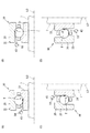
軸受装置10は、図4(A)(B)(C)(D)に示す代表的な四つの形態で用いられる。図4において、(A)は、軸受部20の中心線L0の方向(軸方向)が水平方向であり、給油領域Tが噴出口50よりも低い位置にある場合を示し、(B)は、軸受部20の中心線L0の方向(軸方向)が水平方向であり、給油領域Tが噴出口50よりも高い位置にある場合を示し、(C)は、軸受部20の中心線L0の方向(軸方向)が鉛直方向であり、給油領域Tが噴出口50よりも低い位置にある場合を示し、(D)は、軸受部20の中心線L0の方向(軸方向)が鉛直方向であり、給油領域Tが噴出口50よりも高い位置にある場合を示している。
The initial velocity V0 of the oil droplet ejected from the
The bearing
そして、これら四つの形態のうちのいずれの形態に軸受装置10が設けられていても、噴出口50から油滴として噴出させた潤滑油3が、給油領域T、つまり、内輪軌道溝25に到達できるような初速V0が設定される。
具体的に説明する。本実施形態(軸方向寸法が20ミリ)のアンギュラ玉軸受である軸受部20の場合において、前記直線G0(図3参照)を基準として一方側の偏差δa及び他方側の偏差δbを説明したが、これらのうちの小さい方の偏差(本実施形態ではδb)を、この軸受部20における傾斜角度αについての偏差δと定義する(δ=δb)。幾何学的な形状に基づく計算によれば前記偏差δは2.3°となる。
Then, even if the bearing
This will be specifically described. In the case of the bearing
図5は、図4に示す四つの形態それぞれの場合において、油滴の初速V0(横軸)と、前記直線G0を基準とした場合の傾斜角度αについての偏差δ(縦軸)とを示すグラフである。なお、このグラフはシミュレーション結果である。図5に示すグラフ中の「太い実線」は図4(A)の形態の場合であり、「細い実線」は図4(B)の形態の場合であり、「太い破線」は図4(C)の形態の場合であり、「細い破線」は図4(D)の形態の場合を示している。 FIG. 5 shows the initial velocity V0 of the oil droplet (horizontal axis) and the deviation δ (vertical axis) of the inclination angle α with respect to the straight line G0 in each of the four embodiments shown in FIG. It is a graph. This graph is a simulation result. The “thick solid line” in the graph shown in FIG. 5 corresponds to the case of the form of FIG. 4A, the “thin solid line” corresponds to the form of FIG. 4B, and the “thick broken line” corresponds to the form of FIG. 4), and a “thin broken line” indicates the case of the form of FIG.
図5に示すように、前記四つの形態の全てにおいて偏差δが2.3°以下となる初速V0は1.2メートル/秒以上である。つまり、噴出口50から1.2メートル/秒以上の初速V0で潤滑油3を油滴として噴出すれば、前記軸受部20を含む軸受装置1がどのような姿勢で用いられても、その油滴を給油領域T、つまり内輪軌道溝25に付着させることが可能となる。
As shown in FIG. 5, the initial velocity V0 at which the deviation δ is 2.3 ° or less is 1.2 m / sec or more in all of the four embodiments. That is, if the lubricating
図6は、油滴の初速V0の最小値と、軸受部20の軸方向寸法(幅)との関係を示すグラフである。このグラフにおける前記最小値は、図4に示す各形態のいずれに軸受装置1を適用した場合であっても内輪軌道溝25に油滴を到達させることを可能とするための油滴の初速V0の最小値である。例えば、軸受装置1に含まれる軸受部20の軸方向寸法(幅)が5mmである場合、初速V0の最小値は0.6メートル/秒であり、軸受部20の軸方向寸法(幅)が150mmの軸受の場合、初速V0の最小値は3.3メートル/秒である。図6に示すように、軸受部20の軸方向寸法(幅)が大きくなると、必要となる油滴の初速V0を大きくする必要がある。
以上より、初速V0は、軸受部20のサイズ(特に軸方向寸法)及び給油領域Tの広さに基づいて設定することができる。
FIG. 6 is a graph showing the relationship between the minimum value of the initial velocity V0 of the oil droplet and the axial dimension (width) of the bearing
As described above, the initial speed V0 can be set based on the size (particularly, the axial dimension) of the bearing
以上のように、本実施形態の軸受装置1では、給油ユニット40のポンプ43から、潤滑油3をピコリットルのサイズの油滴とし、しかもその飛行速度を速くして給油領域Tに向けて噴出している。これにより、給油領域Tに対して効率よく潤滑油3を供給することができ、潤滑油3の過剰供給を防ぎ、潤滑油の消費を抑えてタンク42の潤滑油3の無駄使いを防ぐことが可能となる。
As described above, in the
なお、前記実施形態では、軸受部20と共に給油ユニット40を設けて構成した軸受装置10に関して説明したが、この給油ユニット40を工作機械以外に他の回転装置に適用してもよい。例えば、給油ユニット40を、歯車機構の歯車面に対して給油を行うための装置としてもよい。
つまり、図示しないが、給油ユニットを、歯車機構等の回転装置に設けられこの回転装置の給油が必要となる給油領域に潤滑油を供給するための装置とすることができる。この場合においても、その給油ユニットは、潤滑油を溜めるタンクと、この潤滑油を前記給油領域に向かって飛ばすポンプとを有している。そして、このポンプは、前記給油領域に向かって開口している噴出口を有しており、この噴出口から潤滑油を所定の初速(飛行速度)を有する0.5〜1000ピコリットルの油滴として前記給油領域へ噴出するように構成されている。
In the above-described embodiment, the bearing
In other words, although not shown, the oil supply unit may be a device provided in a rotating device such as a gear mechanism for supplying lubricating oil to an oil supply region where the rotating device needs oiling. Also in this case, the lubrication unit has a tank for storing lubricating oil and a pump for blowing the lubricating oil toward the lubricating area. The pump has a spout opening toward the oil supply area, from which the lubricating oil is supplied with 0.5 to 1000 picoliter oil droplets having a predetermined initial speed (flight speed). And is configured to jet to the refueling area.
以上のとおり開示した実施形態はすべての点で例示であって制限的なものではない。つまり、本発明の軸受装置1(給油ユニット40)は、図示する形態に限らず本発明の範囲内において他の形態のものであってもよい。
前記実施形態では、軸受部20がアンギュラ玉軸受である場合について説明したが、軸受の形式はこれに限らず、深溝玉軸受であってもよく、また、円すい転がり軸受や、円筒ころ軸受であってよい。
The embodiments disclosed above are illustrative in all aspects and not restrictive. That is, the bearing device 1 (the refueling unit 40) of the present invention is not limited to the illustrated embodiment, but may be another embodiment within the scope of the present invention.
In the above-described embodiment, the case where the bearing
また、前記実施形態では、内輪21が回転輪である場合について説明したが、外輪22が回転輪であり、内輪21が固定輪であってもよい。この場合、給油ユニット40を、固定輪側となる内輪延長部に取り付ければよい。
Further, in the above embodiment, the case where the
3:潤滑油 10:軸受装置 11:第1の環状空間
12:第2の環状空間 20:軸受部 21:内輪(回転輪)
22:外輪(固定輪) 23:玉(転動体) 24:保持器
40:給油ユニット 42:タンク 43:ポンプ
50:噴出口 50a:開口 T:給油領域
3: Lubricating oil 10: Bearing device 11: First annular space 12: Second annular space 20: Bearing 21: Inner ring (rotating wheel)
22: Outer ring (fixed ring) 23: Ball (rolling element) 24: Cage 40: Refueling unit 42: Tank 43: Pump 50:
Claims (3)
前記転動体及び前記保持器が設けられている第1の環状空間の軸方向の隣に設けられ前記軸受部において給油が必要となる給油領域に潤滑油を供給するための給油ユニットと、を備え、
前記外輪は、前記転動体が転動する軸方向一方側の外輪本体部と、当該外輪本体部の軸方向他方側に設けられている外輪延長部と、を有し、
前記内輪は、前記転動体が転動する軸方向一方側の内輪本体部と、当該内輪本体部の軸方向他方側に設けられている内輪延長部と、を有し、
前記給油ユニットは、潤滑油を溜めるタンクと、前記潤滑油を前記給油領域に向かって飛ばし直接的に潤滑油を当該給油領域に吹き付けるポンプと、を有し、
前記ポンプは、前記給油領域に向かって開口している噴出口を有し、
前記噴出口から前記潤滑油を所定の初速を有する0.5〜1000ピコリットルの油滴として噴出する前記ポンプが、前記外輪延長部と前記内輪延長部との間に形成されている第2の環状空間に、格納されている、軸受装置。 An outer ring, an inner ring coaxial with the outer ring, a plurality of rolling elements interposed between the outer ring and the inner ring, and a bearing unit having a retainer holding the plurality of rolling elements,
An oil supply unit that is provided adjacent to the first annular space in which the rolling elements and the retainer are provided in the axial direction and that supplies lubricating oil to an oil supply area where oil supply is required in the bearing portion. ,
The outer ring has an outer ring body on one axial side where the rolling element rolls, and an outer ring extension provided on the other axial side of the outer ring body,
The inner ring has an inner ring body on one axial side where the rolling elements roll, and an inner ring extension provided on the other axial side of the inner ring body,
The lubrication unit has a tank for storing lubricating oil, and a pump for blowing the lubricating oil toward the lubricating area and directly spraying the lubricating oil to the lubricating area,
The pump has a spout opening toward the refueling area,
A second pump formed between the outer ring extension and the inner ring extension, wherein the pump for injecting the lubricating oil from the jet port as oil droplets of 0.5 to 1000 picoliters having a predetermined initial velocity is formed. A bearing device stored in an annular space.
Priority Applications (4)
| Application Number | Priority Date | Filing Date | Title |
|---|---|---|---|
| JP2015140468A JP6648432B2 (en) | 2015-07-14 | 2015-07-14 | Bearing device and lubrication unit |
| US15/204,352 US10030709B2 (en) | 2015-07-14 | 2016-07-07 | Bearing apparatus and lubrication unit |
| DE102016112681.0A DE102016112681A1 (en) | 2015-07-14 | 2016-07-11 | Bearing device and lubrication unit |
| CN201610551948.5A CN106351958B (en) | 2015-07-14 | 2016-07-13 | Bearing device and oil supply unit |
Applications Claiming Priority (1)
| Application Number | Priority Date | Filing Date | Title |
|---|---|---|---|
| JP2015140468A JP6648432B2 (en) | 2015-07-14 | 2015-07-14 | Bearing device and lubrication unit |
Related Child Applications (1)
| Application Number | Title | Priority Date | Filing Date |
|---|---|---|---|
| JP2016218816A Division JP6665758B2 (en) | 2016-11-09 | 2016-11-09 | Bearing device |
Publications (2)
| Publication Number | Publication Date |
|---|---|
| JP2017020611A JP2017020611A (en) | 2017-01-26 |
| JP6648432B2 true JP6648432B2 (en) | 2020-02-14 |
Family
ID=57630372
Family Applications (1)
| Application Number | Title | Priority Date | Filing Date |
|---|---|---|---|
| JP2015140468A Active JP6648432B2 (en) | 2015-07-14 | 2015-07-14 | Bearing device and lubrication unit |
Country Status (4)
| Country | Link |
|---|---|
| US (1) | US10030709B2 (en) |
| JP (1) | JP6648432B2 (en) |
| CN (1) | CN106351958B (en) |
| DE (1) | DE102016112681A1 (en) |
Families Citing this family (2)
| Publication number | Priority date | Publication date | Assignee | Title |
|---|---|---|---|---|
| JP2018173127A (en) | 2017-03-31 | 2018-11-08 | 株式会社ジェイテクト | Rolling bearing device and oil supply unit |
| JP7087335B2 (en) * | 2017-10-13 | 2022-06-21 | 株式会社ジェイテクト | Anomaly detection method for rolling bearing devices and bearings |
Family Cites Families (35)
| Publication number | Priority date | Publication date | Assignee | Title |
|---|---|---|---|---|
| NL8902384A (en) * | 1989-09-25 | 1991-04-16 | Skf Ind Trading & Dev | ROLLER BEARING INCLUDING A LUBRICATOR PUMP. |
| US5368582A (en) * | 1992-08-10 | 1994-11-29 | The Schepens Eye Research Institute | Method and apparatus for introducing fluid material into an eye |
| US6808749B2 (en) * | 2001-10-10 | 2004-10-26 | Seiko Epson Corporation | Thin film forming method, solution and apparatus for use in the method, and electronic device fabricating method |
| GB2382385B (en) * | 2001-11-23 | 2005-07-20 | Nsk Europ Technology Co Ltd | A bearing lubrication system and a process of lubricating a bearing |
| JP2003207094A (en) * | 2002-01-15 | 2003-07-25 | Nsk Ltd | Spindle device |
| JP4089363B2 (en) | 2002-09-13 | 2008-05-28 | 株式会社ジェイテクト | Rolling bearing device |
| WO2004025130A1 (en) * | 2002-09-13 | 2004-03-25 | Koyo Seiko Co., Ltd. | Bearing device |
| JP2006125540A (en) | 2004-10-29 | 2006-05-18 | Jtekt Corp | Rolling bearing device and spindle |
| EP1811190B1 (en) | 2004-10-29 | 2010-12-15 | JTEKT Corporation | Rolling bearing device and spindle |
| WO2006064858A1 (en) | 2004-12-14 | 2006-06-22 | Jtekt Corporation | Rolling bearing device |
| JP2006200740A (en) | 2004-12-24 | 2006-08-03 | Jtekt Corp | Rolling bearing device |
| JP2006258192A (en) | 2005-03-17 | 2006-09-28 | Jtekt Corp | Rolling bearing device and rotary device |
| JP4525911B2 (en) | 2005-01-17 | 2010-08-18 | 株式会社ジェイテクト | Rolling bearing device |
| JP2006194402A (en) | 2005-01-17 | 2006-07-27 | Jtekt Corp | Rolling bearing device |
| US7883271B2 (en) | 2005-01-17 | 2011-02-08 | Jtekt Corporation | Rolling bearing device and rotary apparatus |
| JP2006214470A (en) | 2005-02-01 | 2006-08-17 | Jtekt Corp | Roller bearing device |
| JP4424293B2 (en) * | 2005-09-29 | 2010-03-03 | 株式会社ジェイテクト | Rolling bearing device |
| JP2007132486A (en) | 2005-11-14 | 2007-05-31 | Jtekt Corp | Bearing device for generator, and generator |
| JP2007132487A (en) | 2005-11-14 | 2007-05-31 | Jtekt Corp | Touchdown bearing device for turbo molecular pump |
| JP2007138963A (en) | 2005-11-14 | 2007-06-07 | Jtekt Corp | Vacuum rolling bearing device |
| JP2007139036A (en) | 2005-11-17 | 2007-06-07 | Jtekt Corp | Lubricating device |
| JP5607285B2 (en) * | 2006-06-23 | 2014-10-15 | 日本精工株式会社 | Bearing device |
| JP2008106900A (en) | 2006-10-27 | 2008-05-08 | Jtekt Corp | Rolling bearing device |
| DE102007042364B4 (en) * | 2007-09-06 | 2010-01-28 | Schaeffler Kg | Bearing with liquid supply system, in particular with lubricant supply system |
| EP2071203B1 (en) * | 2007-12-10 | 2015-02-25 | JTEKT Corporation | Rolling bearing and rolling bearing assembly |
| JP2009144782A (en) * | 2007-12-12 | 2009-07-02 | Jtekt Corp | Oil feed monitor and method, and rolling bearing device |
| EP2619453A1 (en) * | 2010-09-21 | 2013-07-31 | XEMC Darwind BV | Wind turbine with oil lubrication |
| EP2757278A4 (en) * | 2011-09-13 | 2015-09-30 | Ntn Toyo Bearing Co Ltd | Bearing device |
| DE102012200777A1 (en) * | 2012-01-20 | 2013-07-25 | Aktiebolaget Skf | Bearing device for e.g. wind-power plant, has control unit controlling lubrication unit depending on deviation of detected value from reference value such that bearing operating characteristic reaches reference value during operation |
| JP5989454B2 (en) * | 2012-08-20 | 2016-09-07 | Ntn株式会社 | Rolling bearing device |
| JP6168338B2 (en) | 2013-02-13 | 2017-07-26 | 株式会社ジェイテクト | Rolling bearing device |
| JP6124056B2 (en) | 2013-02-13 | 2017-05-10 | 株式会社ジェイテクト | Rolling bearing device |
| JP2014159853A (en) * | 2013-02-20 | 2014-09-04 | Jtekt Corp | Bearing unit and eccentric swing type speed reducer having bearing unit |
| JP6160125B2 (en) * | 2013-03-01 | 2017-07-12 | 株式会社ジェイテクト | Rolling bearing device |
| JP2016023757A (en) * | 2014-07-23 | 2016-02-08 | 株式会社ジェイテクト | Rolling bearing device and oil supply unit |
-
2015
- 2015-07-14 JP JP2015140468A patent/JP6648432B2/en active Active
-
2016
- 2016-07-07 US US15/204,352 patent/US10030709B2/en not_active Expired - Fee Related
- 2016-07-11 DE DE102016112681.0A patent/DE102016112681A1/en not_active Withdrawn
- 2016-07-13 CN CN201610551948.5A patent/CN106351958B/en not_active Expired - Fee Related
Also Published As
| Publication number | Publication date |
|---|---|
| CN106351958A (en) | 2017-01-25 |
| CN106351958B (en) | 2020-01-10 |
| DE102016112681A1 (en) | 2017-01-19 |
| US10030709B2 (en) | 2018-07-24 |
| JP2017020611A (en) | 2017-01-26 |
| US20170016481A1 (en) | 2017-01-19 |
Similar Documents
| Publication | Publication Date | Title |
|---|---|---|
| JP6665758B2 (en) | Bearing device | |
| JP6648432B2 (en) | Bearing device and lubrication unit | |
| CN108194516B (en) | Rolling bearing device, oil supply unit, method for supplying lubricating oil, and storage medium | |
| JP2018087595A (en) | Rolling bearing device and oil supply unit | |
| JP6750296B2 (en) | Rolling bearing device | |
| US9638257B2 (en) | Rolling bearing apparatus | |
| JP2017125550A (en) | Bearing device | |
| JP2014062618A (en) | Lubricating structure of bearing device | |
| JP2018084324A (en) | Rolling bearing device | |
| CN108071690B (en) | Rolling bearing device | |
| US10240636B2 (en) | Rolling bearing device and oil supply unit | |
| JP2005090713A (en) | Bearing device | |
| JP2017219100A (en) | Rolling bearing device | |
| JP2018009623A (en) | Bearing device and oil supply unit | |
| US9909622B2 (en) | Rolling bearing device | |
| JP6555220B2 (en) | Rolling bearing device | |
| JP2020008107A (en) | Rolling bearing device | |
| JP6677070B2 (en) | Rolling bearing device | |
| JP2020008066A (en) | Rolling bearing device | |
| JP2018017289A (en) | Rolling bearing device and oil feeding unit | |
| JP6434094B2 (en) | Lubrication structure of bearing device | |
| JP2020026848A (en) | Rolling bearing device | |
| JP2020063782A (en) | Lubricating device and rolling bearing device |
Legal Events
| Date | Code | Title | Description |
|---|---|---|---|
| A621 | Written request for application examination |
Free format text: JAPANESE INTERMEDIATE CODE: A621 Effective date: 20180615 |
|
| A977 | Report on retrieval |
Free format text: JAPANESE INTERMEDIATE CODE: A971007 Effective date: 20190510 |
|
| A131 | Notification of reasons for refusal |
Free format text: JAPANESE INTERMEDIATE CODE: A131 Effective date: 20190528 |
|
| A521 | Written amendment |
Free format text: JAPANESE INTERMEDIATE CODE: A523 Effective date: 20190705 |
|
| A131 | Notification of reasons for refusal |
Free format text: JAPANESE INTERMEDIATE CODE: A131 Effective date: 20190924 |
|
| A521 | Written amendment |
Free format text: JAPANESE INTERMEDIATE CODE: A523 Effective date: 20191118 |
|
| TRDD | Decision of grant or rejection written | ||
| A01 | Written decision to grant a patent or to grant a registration (utility model) |
Free format text: JAPANESE INTERMEDIATE CODE: A01 Effective date: 20191217 |
|
| A61 | First payment of annual fees (during grant procedure) |
Free format text: JAPANESE INTERMEDIATE CODE: A61 Effective date: 20191230 |
|
| R150 | Certificate of patent or registration of utility model |
Ref document number: 6648432 Country of ref document: JP Free format text: JAPANESE INTERMEDIATE CODE: R150 |