JP2006200740A - Rolling bearing device - Google Patents
Rolling bearing device Download PDFInfo
- Publication number
- JP2006200740A JP2006200740A JP2005366271A JP2005366271A JP2006200740A JP 2006200740 A JP2006200740 A JP 2006200740A JP 2005366271 A JP2005366271 A JP 2005366271A JP 2005366271 A JP2005366271 A JP 2005366271A JP 2006200740 A JP2006200740 A JP 2006200740A
- Authority
- JP
- Japan
- Prior art keywords
- nozzle
- lubricant
- tip
- rolling bearing
- bearing device
- Prior art date
- Legal status (The legal status is an assumption and is not a legal conclusion. Google has not performed a legal analysis and makes no representation as to the accuracy of the status listed.)
- Pending
Links
Images


Abstract
Description
本発明は、転がり軸受装置に関し、更に詳しくは、互いに相対回転する軌道部材の間に形成された環状空間内あるいはその開口近傍に、潤滑剤を供給する手段を備えた転がり軸受装置に関する。 The present invention relates to a rolling bearing device, and more particularly to a rolling bearing device provided with means for supplying a lubricant in an annular space formed between race members rotating relative to each other or in the vicinity of the opening thereof.
従来、高速で回転中の転がり軸受装置の環状空間内に潤滑剤を供給する方法として、ジェット潤滑、オイルミスト潤滑やオイル/エア潤滑等が用いられている。 Conventionally, jet lubrication, oil mist lubrication, oil / air lubrication, and the like have been used as a method of supplying a lubricant into the annular space of a rolling bearing device rotating at high speed.
しかしながら、これらの方法は、環状空間の外側からその内側に潤滑剤を到達させるために、潤滑剤を加圧したり、圧縮空気等により潤滑剤を加速したりする必要があり、機構が大掛かりとなってしまう。また、必要以上の油量が供給されてしまうために潤滑剤の無駄が多く、環境の汚染等を防止するため、余分な潤滑剤を回収して循環させる機構等を必要としていた。 However, in these methods, it is necessary to pressurize the lubricant or accelerate the lubricant with compressed air or the like in order to allow the lubricant to reach the inside from the outside of the annular space, and the mechanism becomes large. End up. Further, since an excessive amount of oil is supplied, a lot of lubricant is wasted, and in order to prevent environmental pollution and the like, a mechanism for collecting and circulating excess lubricant is required.
そこで、本出願人らは、軌道部材の間に形成された環状空間内あるいはその開口近傍に、一体化されたコンパクトな潤滑剤供給ユニット(以下「給油ユニット」と称する)を備えるとともに、この給油ユニットのノズルを軸受の環状空間内に配置することにより、必要に応じた最小限の量の潤滑剤を転動体近傍あるいは保持器近傍に直接供給することのできる転がり軸受装置を提案している(特許文献1〜2等を参照)。
Therefore, the applicants are provided with an integrated compact lubricant supply unit (hereinafter referred to as “oil supply unit”) in the annular space formed between the track members or in the vicinity of the opening thereof. A rolling bearing device has been proposed in which the nozzle of the unit is arranged in the annular space of the bearing so that a minimum amount of lubricant as required can be directly supplied to the vicinity of the rolling element or the vicinity of the cage ( (See
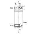
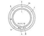
図7は、これらの提案に係る転がり軸受装置の軸方向断面図であり、図8は、図7のX−X線矢視断面図である。また、図9は、この転がり軸受装置に用いられている給油ユニットに設けられた潤滑剤供給用ノズルを軸受径方向から見た模式的断面図(a)、およびこのノズルを軸受周方向から見た図(b)である。 FIG. 7 is an axial cross-sectional view of the rolling bearing device according to these proposals, and FIG. 8 is a cross-sectional view taken along line XX in FIG. FIG. 9 is a schematic sectional view (a) of the lubricant supply nozzle provided in the oil supply unit used in the rolling bearing device as seen from the bearing radial direction, and the nozzle as seen from the bearing circumferential direction. FIG.
この転がり軸受装置は、軌道部材としての内輪1および外輪2と、これら内外輪の対向面(軌道面)間に形成される環状空間S内に配置された複数の転動体(ボール3)と、これらのボール3を周方向に所定の間隔で保持する保持器4と、潤滑剤を供給する給油ユニット10とから構成されている。
The rolling bearing device includes an
給油ユニット10は、ポンプ5と、このポンプ5の制御手段6と、潤滑剤貯留用のタンク7と、電池8とからなり、これら全てが軸受の環状空間S内に納まるように配置されている。制御手段6とタンク7および電池8は、軸方向から見た場合、略円弧状であり、これらと前記ポンプ5とが結合して、全体として輪状のユニット体として構成されている。なお、この給油ユニット10は、軸受の対向面の固定輪側(この例においては外輪2の内周面2x)に取り付けられている。
The
また、この給油ユニット10のポンプ5に配設された潤滑剤供給用のノズル21は、図9(a)および図9(b)のようなパイプ状部材からなり、その先端部21aの端面には、潤滑剤を吐出するための開口(穴21c)が設けられている。このノズル21の先端部21aは、保持器4と内輪1との間で、かつ、ボール3の転動軌道の近傍となる位置に配置されている。
Further, the
なお、ボールを保持する保持器を有さない軸受装置の場合は、図10および図11のように、ポンプ5のノズル21の先端部21aは、外輪2と内輪1との間で、かつ、ボール3の転動軌道の近傍となる位置に配置される。
ところで、転がり軸受の環状空間内では、転動体の転動運動により、軸受周方向に空気の流れ(気流)が発生していることが知られている。そのため、加速(加圧)されていない極微量の潤滑剤を用いる上記給油ユニット10では、潤滑剤をこの気流による障壁(エアバリアあるいはエアーカーテン)の内側にまで到達させ、必要な部位に効率良く供給(滴下)するために、ノズル21の先端部21aを環状空間S内のボール3近傍まで挿入している。
Incidentally, it is known that an air flow (air flow) is generated in the circumferential direction of the bearing due to the rolling motion of the rolling elements in the annular space of the rolling bearing. Therefore, in the
しかしながら、従来の転がり軸受装置においては、図6(b)のように、このノズル先端の穴21cから吐出された潤滑剤Oが、前記気流の影響と表面張力により、ノズル外周面21xを伝ってポンプ5側のノズル根元部21b方向に移動してしまい、狙った部位への安定的な滴下が困難になる場合があった。
However, in the conventional rolling bearing device, as shown in FIG. 6B, the lubricant O discharged from the
本発明は、上記する課題に対処するためになされたものであり、潤滑剤を所要の部位へ的確に滴下することが可能で、少量の潤滑剤でも良好な潤滑を維持することができる転がり軸受装置を提供することを目的としている。 The present invention has been made in order to cope with the above-described problems, and is a rolling bearing capable of accurately dropping a lubricant onto a required portion and maintaining good lubrication even with a small amount of lubricant. The object is to provide a device.
前記の目的を達成するために、請求項1に記載の発明は、同心状に配置されて相対回転する軌道部材どうしの間に形成される環状空間の中またはその近傍に、パイプ状のノズルを備えるポンプを配設し、このノズルの先端を、当該環状空間の中に配置するとともに、前記ノズル先端に設けられた開口から、前記環状空間内に配置された転動体の近傍に潤滑剤を供給する転がり軸受装置において、前記ノズルの先端もしくはその先端近傍に、このノズルの周面から少なくとも鉛直下方に向かって突出する潤滑剤保持部が形成されていることを特徴とする。 In order to achieve the above object, according to the first aspect of the present invention, a pipe-like nozzle is provided in or near an annular space formed between raceway members arranged concentrically and relatively rotating. A pump is provided, and the tip of the nozzle is disposed in the annular space, and a lubricant is supplied to the vicinity of the rolling elements disposed in the annular space from the opening provided in the nozzle tip. In this rolling bearing device, a lubricant holding portion that protrudes at least vertically downward from the peripheral surface of the nozzle is formed at or near the tip of the nozzle.
本発明は、給油ノズルを転動体あるいは保持器近傍にまで挿入して、ポンプにより潤滑剤の供給を行う転がり軸受装置において、このノズルの先端吐出口の近傍に、吐出された潤滑剤を寄せ集めて液滴とする潤滑剤保持部を設けることにより、所期の目的を達成しようとするものである。 The present invention relates to a rolling bearing device in which an oil supply nozzle is inserted to the vicinity of a rolling element or a cage, and a lubricant is supplied by a pump, and the discharged lubricant is collected near the tip discharge port of the nozzle. By providing a lubricant holding portion for forming droplets, the intended purpose is achieved.
すなわち、請求項1に記載の発明によれば、前記ノズルの先端もしくはその先端近傍に、ノズルの周面から少なくとも鉛直下方に向かって突出する潤滑剤保持部を形成することにより、ノズル先端から吐出された潤滑剤がこの潤滑剤保持部に引き寄せられ、ノズルの根元部側に移動し難くなる。従って、本発明の転がり軸受装置は、転動体の転動運動により気流が発生している環状空間内にノズル先端を配置した場合でも、潤滑剤を所要の部位へ的確に滴下することができる。 That is, according to the first aspect of the present invention, the lubricant holding portion that protrudes at least vertically downward from the peripheral surface of the nozzle is formed at or near the tip of the nozzle to discharge from the tip of the nozzle. The applied lubricant is attracted to the lubricant holding part, and it becomes difficult to move to the base part side of the nozzle. Therefore, the rolling bearing device of the present invention can accurately drop the lubricant onto a required portion even when the nozzle tip is disposed in the annular space where the airflow is generated by the rolling motion of the rolling elements.
ここで、前記潤滑剤保持部の具体的形成手段として、ノズルの先端近傍をその他の部位より大径とする方法(請求項2)、ノズルの先端開口径をその他の部位の内径より大きくする方法(請求項3)、あるいは、このノズルの外周面に環状部材を嵌め入れる方法(請求項4)を好適に採用することができる。 Here, as a specific means for forming the lubricant holding portion, a method in which the vicinity of the tip of the nozzle is made larger in diameter than the other part (Claim 2), and a method in which the nozzle opening diameter is made larger than the inner diameter of the other part (Claim 3) Alternatively, a method (Claim 4) in which an annular member is fitted into the outer peripheral surface of the nozzle can be suitably employed.
請求項2および請求項3に記載の構成により、上記潤滑剤保持部を容易に形成することができる。また、このノズルが例えば注射針のような非常に径の小さなパイプ状で、ノズルの強度不足により先端部への加工が困難な場合は、その先端近傍の外周に環状部材を嵌め入れても良い。 With the configuration according to the second and third aspects, the lubricant holding portion can be easily formed. In addition, when the nozzle is in the shape of a pipe having a very small diameter such as an injection needle and it is difficult to process the tip due to insufficient strength of the nozzle, an annular member may be fitted on the outer periphery in the vicinity of the tip. .
以上のように、本発明によれば、転動体の転動運動により気流が発生している転がり軸受の環状空間内に潤滑剤供給ノズルを配置した場合でも、潤滑剤を所要の部位へ的確に滴下することができる。また、供給される潤滑剤に無駄がなく、少量の潤滑剤で転がり軸受装置の良好な潤滑を維持することが可能になる。 As described above, according to the present invention, even when the lubricant supply nozzle is disposed in the annular space of the rolling bearing in which an air flow is generated by the rolling motion of the rolling elements, the lubricant is accurately supplied to a required portion. Can be dripped. Further, there is no waste in the supplied lubricant, and good lubrication of the rolling bearing device can be maintained with a small amount of lubricant.
以下、図面を参照しつつこの発明を実施するための形態について説明する。
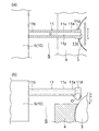
図1は、本発明の第1実施形態における転がり軸受装置に用いられている給油ユニット10に設けられた潤滑剤供給用ノズルを軸受径方向から見た模式的断面図(a)、およびこのノズルを軸受周方向から見た図(b)である。なお、この転がり軸受装置全体の構成は、図7および図8で示した従来例と同様であるため、その詳細な説明は省略する。また、従来例と同様の機能を有する構成部材には、同じ符号を付記する。
Hereinafter, embodiments for carrying out the present invention will be described with reference to the drawings.
FIG. 1 is a schematic cross-sectional view (a) of a lubricant supply nozzle provided in an
本実施形態における転がり軸受装置も、軌道部材としての内輪1および外輪2と、これら内外輪の対向面間に形成される環状空間S内に配置された複数のボール3と、これらのボール3を周方向に所定の間隔で保持する保持器4と、潤滑剤を供給する給油ユニット10とから構成されている。
The rolling bearing device according to the present embodiment also includes an
また、給油ユニット10は、ポンプ5と、ポンプ5の制御手段6と、潤滑剤貯留用のタンク7と、電池8とからなり、軸受の対向面の固定輪側(外輪2の内周面2x)に取り付けられているとともに、このポンプ5の軸受中央側端面には、先端部11aに潤滑剤を吐出するための穴11cが設けられたノズル11が配設されている。
The
本実施形態における転がり軸受装置の特徴は、潤滑剤Oを供給するノズル11の先端部11aに、その他の部位より大径の大径部11dが形成されている点である。
A feature of the rolling bearing device in the present embodiment is that a large-
以上の構成の転がり軸受装置においても、軸受が回転した場合、ボール3の転動により環状空間S内には図中の矢印で示される向き(軸受周方向)に気流が発生する。しかしながら、この転がり軸受装置は、ノズル11の先端に潤滑剤保持部となる大径部11dが形成されていることから、吐出された潤滑剤Oは、ノズル根元部11b方向に移動することなく、この大径部11dの鉛直下方に油滴となって寄せ集められることとなる。
Also in the rolling bearing device having the above-described configuration, when the bearing rotates, an air flow is generated in the annular space S in the direction indicated by the arrow (the bearing circumferential direction) due to the rolling of the
従って、本実施形態における転がり軸受装置は、吐出された潤滑剤Oを、最も効率の良いボール3近傍あるいは保持器4近傍に安定的に滴下することができる。また、供給される潤滑剤に無駄がなく、少量の潤滑剤でも良好な軸受潤滑を維持することが可能になる。
Therefore, the rolling bearing device in the present embodiment can stably drop the discharged lubricant O in the vicinity of the
なお、ノズル11先端の潤滑剤保持部(大径部11d)は、必ずしもノズル11の周方向に一様に形成する必要はなく、少なくとも軸受における鉛直下方に向かって膨出(突出)する形状であれば、どのような形状でも良い。
The lubricant holding portion (large-
また、ボールを保持する保持器を有さない軸受装置(図10,11を参照)の場合、図2のように、ポンプ5のノズル11の先端部11aは、環状空間S内のボール3転動軌道の近傍に配置されることとなる。この場合も、上記と同様の効果が得られることは言うまでもない。
Further, in the case of a bearing device (see FIGS. 10 and 11) that does not have a cage for holding the ball, the
次に、本発明の第2・第3実施形態について説明する。
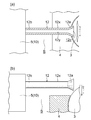
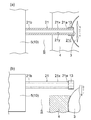
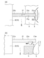
図3,4および図5,6は、本発明の第2および第3実施形態における転がり軸受装置に用いられている給油ユニット10に設けられた潤滑剤供給用ノズルを軸受径方向から見た模式的断面図(a)と、このノズルを軸受周方向から見た図(b)である。
Next, second and third embodiments of the present invention will be described.
3 and 4 and FIGS. 5 and 6 are schematic views of the lubricant supply nozzle provided in the
この第2実施形態が第1実施形態と異なる点は、吐出された潤滑剤を油滴として寄せ集める潤滑剤保持部が、ノズル先端の穴12cの開口径を、その他の部位の内周面12yの径より大きくすることにより形成されている点である。
This second embodiment is different from the first embodiment in that the lubricant holding part that collects the discharged lubricant as oil droplets reduces the opening diameter of the
また、第3実施形態においては、この潤滑剤保持部が、ノズル先端部21aに嵌め入れられた環状部材13により形成されている。なお、この環状部材13は、例えば接着剤等により、このノズル21の外周面21xに固定されている。
Moreover, in 3rd Embodiment, this lubricant holding | maintenance part is formed of the
これらの構成によっても、ポンプ5から吐出された潤滑剤は、潤滑剤保持部(ノズル先端部12aまたは環状部材13)の鉛直下方に油滴となって寄せ集められ、ノズル根元部方向に移動することがない。従って、これらの実施形態における転がり軸受装置も、吐出された潤滑剤を、ボール3近傍あるいは保持器4近傍に安定的に滴下することができる。また、供給される潤滑剤に無駄がなく、少量の潤滑剤でも良好な軸受潤滑を維持することが可能になる。
Even with these configurations, the lubricant discharged from the
なお、第1実施形態と同様、ボールを保持する保持器を有さない軸受装置の場合、図4および図6のように、ポンプ5のノズル12,21の先端部12a,21aは、環状空間S内のボール3転動軌道の近傍に配置されることとなる。この場合も、上記と同様の効果が得られることは勿論である。
As in the first embodiment, in the case of a bearing device that does not have a cage for holding a ball, the
また、これらの実施形態においても、ノズル先端の潤滑剤保持部は、必ずしもノズルの周方向に一様に形成する必要はなく、少なくとも軸受における鉛直下方に向かって突出する形状であれば良い。例えば、第2実施形態における先端部12aの開口形状として、例示のラッパ形状の他に、ノズル周方向に花びら形や星形等に形成しても良い。
Also in these embodiments, the lubricant holding portion at the tip of the nozzle does not necessarily have to be formed uniformly in the circumferential direction of the nozzle, and may be any shape that projects at least vertically downward in the bearing. For example, the opening shape of the
更にまた、軸受の構成や給油ユニットの構造も、これら第1〜第3実施形態での例に限定されず、本発明は、潤滑剤給油ノズルを転動体あるいは保持器近傍にまで挿入して、ポンプにより潤滑剤の供給を行う転がり軸受装置に広く適用することができる。 Furthermore, the structure of the bearing and the structure of the oil supply unit are not limited to the examples in the first to third embodiments, and the present invention inserts the lubricant oil supply nozzle to the vicinity of the rolling element or the cage, The present invention can be widely applied to rolling bearing devices that supply a lubricant by a pump.
例えば、軸受の固定輪に軸方向に隣接する環状部材(間座等)を有する軸受装置の場合は、給油ユニットをこの環状部材の中に配置することも可能である。これらの場合も、ポンプのノズルの先端部は、環状空間内のボール転動軌道あるいは保持器の近傍に潤滑剤を供給する位置に配置される。更には、軸受の固定輪と環状部材との間に、別の中間部材を介在させた構成としても良い。これらの構成の軸受装置においても、同様の効果を奏することができることは言うまでもない。 For example, in the case of a bearing device having an annular member (such as a spacer) adjacent to the fixed ring of the bearing in the axial direction, the oil supply unit can be disposed in the annular member. Also in these cases, the tip of the nozzle of the pump is arranged at a position where the lubricant is supplied in the vicinity of the ball rolling track or the cage in the annular space. Furthermore, another intermediate member may be interposed between the bearing fixed ring and the annular member. It goes without saying that the same effect can be obtained in the bearing device having these configurations.
1 内輪
2 外輪
2x 内周面
3 ボール
4 保持器
5 ポンプ
6 制御手段
7 タンク
8 電池
10 給油ユニット
11 ノズル
11a 先端部 11b 根元部 11c 穴(開口)
11d 大径部(潤滑剤保持部) 11x 外周面 11y 内周面
12 ノズル
12a 先端部(潤滑剤保持部) 12b 根元部 12c 穴(開口)
12x 外周面 12y 内周面
13 環状部材(潤滑剤保持部)
21 ノズル
21a 先端部 21b 根元部 21c 穴(開口)
21x 外周面 21y 内周面
O 潤滑剤
S 環状空間
DESCRIPTION OF
11d Large diameter part (lubricant holding part) 11x Outer
12x outer
21
21x outer
Claims (4)
前記ノズルの先端もしくはその先端近傍に、このノズルの周面から少なくとも鉛直下方に向かって突出する潤滑剤保持部が形成されていることを特徴とする転がり軸受装置。 A pump having a pipe-shaped nozzle is disposed in or near the annular space formed between the concentric and relatively rotating track members, and the tip of the nozzle is placed in the annular space. In the rolling bearing device for supplying the lubricant to the vicinity of the rolling elements arranged in the annular space from the opening provided at the nozzle tip,
A rolling bearing device characterized in that a lubricant holding portion that protrudes at least vertically downward from the peripheral surface of the nozzle is formed at or near the tip of the nozzle.
The rolling bearing device according to claim 1, wherein the lubricant holding portion is formed by an annular member fitted on an outer periphery of the nozzle.
Priority Applications (1)
| Application Number | Priority Date | Filing Date | Title |
|---|---|---|---|
| JP2005366271A JP2006200740A (en) | 2004-12-24 | 2005-12-20 | Rolling bearing device |
Applications Claiming Priority (2)
| Application Number | Priority Date | Filing Date | Title |
|---|---|---|---|
| JP2004372682 | 2004-12-24 | ||
| JP2005366271A JP2006200740A (en) | 2004-12-24 | 2005-12-20 | Rolling bearing device |
Publications (1)
| Publication Number | Publication Date |
|---|---|
| JP2006200740A true JP2006200740A (en) | 2006-08-03 |
Family
ID=36958911
Family Applications (1)
| Application Number | Title | Priority Date | Filing Date |
|---|---|---|---|
| JP2005366271A Pending JP2006200740A (en) | 2004-12-24 | 2005-12-20 | Rolling bearing device |
Country Status (1)
| Country | Link |
|---|---|
| JP (1) | JP2006200740A (en) |
Cited By (3)
| Publication number | Priority date | Publication date | Assignee | Title |
|---|---|---|---|---|
| JP2016142393A (en) * | 2015-02-04 | 2016-08-08 | 日本精工株式会社 | Rolling bearing |
| US10030709B2 (en) | 2015-07-14 | 2018-07-24 | Jtekt Corporation | Bearing apparatus and lubrication unit |
| CN116951285A (en) * | 2023-09-18 | 2023-10-27 | 常州市华立液压润滑设备有限公司 | Oil mist lubricating device for machine pump friction pair |
Citations (3)
| Publication number | Priority date | Publication date | Assignee | Title |
|---|---|---|---|---|
| JPH0323065U (en) * | 1989-07-11 | 1991-03-11 | ||
| JPH09122540A (en) * | 1995-11-01 | 1997-05-13 | Horikawa Seisakusho:Kk | Fluid spraying nozzle and fluid spraying device using the same |
| JP2004108388A (en) * | 2002-09-13 | 2004-04-08 | Koyo Seiko Co Ltd | Rolling bearing device |
-
2005
- 2005-12-20 JP JP2005366271A patent/JP2006200740A/en active Pending
Patent Citations (3)
| Publication number | Priority date | Publication date | Assignee | Title |
|---|---|---|---|---|
| JPH0323065U (en) * | 1989-07-11 | 1991-03-11 | ||
| JPH09122540A (en) * | 1995-11-01 | 1997-05-13 | Horikawa Seisakusho:Kk | Fluid spraying nozzle and fluid spraying device using the same |
| JP2004108388A (en) * | 2002-09-13 | 2004-04-08 | Koyo Seiko Co Ltd | Rolling bearing device |
Cited By (9)
| Publication number | Priority date | Publication date | Assignee | Title |
|---|---|---|---|---|
| JP2016142393A (en) * | 2015-02-04 | 2016-08-08 | 日本精工株式会社 | Rolling bearing |
| WO2016125555A1 (en) * | 2015-02-04 | 2016-08-11 | 日本精工株式会社 | Anti-friction bearing |
| KR20170102529A (en) * | 2015-02-04 | 2017-09-11 | 닛본 세이고 가부시끼가이샤 | Anti-friction bearing |
| TWI603011B (en) * | 2015-02-04 | 2017-10-21 | Nsk Ltd | Rolling bearings |
| KR101935707B1 (en) | 2015-02-04 | 2019-01-04 | 닛본 세이고 가부시끼가이샤 | Anti-friction bearing |
| US10184515B2 (en) | 2015-02-04 | 2019-01-22 | Nsk Ltd. | Anti-friction bearing |
| US10030709B2 (en) | 2015-07-14 | 2018-07-24 | Jtekt Corporation | Bearing apparatus and lubrication unit |
| CN116951285A (en) * | 2023-09-18 | 2023-10-27 | 常州市华立液压润滑设备有限公司 | Oil mist lubricating device for machine pump friction pair |
| CN116951285B (en) * | 2023-09-18 | 2023-11-28 | 常州市华立液压润滑设备有限公司 | Oil mist lubricating device for machine pump friction pair |
Similar Documents
| Publication | Publication Date | Title |
|---|---|---|
| EP1811190B1 (en) | Rolling bearing device and spindle | |
| CN100572835C (en) | Rolling bearing system and axle | |
| CN101080582B (en) | Rolling bearing device | |
| JP2006194402A (en) | Rolling bearing device | |
| JP2016023757A (en) | Rolling bearing device and oil supply unit | |
| JP2007303558A (en) | Rolling bearing device | |
| JP2008075882A (en) | Bearing device | |
| JP2010127399A (en) | Bearing lubricating device | |
| JP5045411B2 (en) | Rolling bearing | |
| JP2006200740A (en) | Rolling bearing device | |
| JP6750296B2 (en) | Rolling bearing device | |
| JP2008075738A (en) | Bearing device | |
| JP2007292117A (en) | Rolling bearing | |
| JP4189677B2 (en) | Bearing device and spindle device | |
| JP2014169730A (en) | Rolling bearing device | |
| JP2009079497A (en) | Supercharger | |
| JP2009144781A (en) | Rolling bearing and rolling bearing device | |
| JP5045409B2 (en) | Rolling bearing | |
| JP2005090713A (en) | Bearing device | |
| JP2016151283A (en) | Rolling bearing device | |
| JP2008075857A (en) | Rolling bearing device | |
| JP4569775B2 (en) | Rolling bearing device | |
| JP4471122B2 (en) | Rolling bearing device | |
| JP2006214470A (en) | Roller bearing device | |
| JP2017219100A (en) | Rolling bearing device |
Legal Events
| Date | Code | Title | Description |
|---|---|---|---|
| A621 | Written request for application examination |
Effective date: 20081125 Free format text: JAPANESE INTERMEDIATE CODE: A621 |
|
| A977 | Report on retrieval |
Effective date: 20091210 Free format text: JAPANESE INTERMEDIATE CODE: A971007 |
|
| A131 | Notification of reasons for refusal |
Effective date: 20100210 Free format text: JAPANESE INTERMEDIATE CODE: A131 |
|
| A02 | Decision of refusal |
Free format text: JAPANESE INTERMEDIATE CODE: A02 Effective date: 20100609 |