JP6648025B2 - Pressure display for vibrating expiratory positive pressure device - Google Patents
Pressure display for vibrating expiratory positive pressure device Download PDFInfo
- Publication number
- JP6648025B2 JP6648025B2 JP2016550789A JP2016550789A JP6648025B2 JP 6648025 B2 JP6648025 B2 JP 6648025B2 JP 2016550789 A JP2016550789 A JP 2016550789A JP 2016550789 A JP2016550789 A JP 2016550789A JP 6648025 B2 JP6648025 B2 JP 6648025B2
- Authority
- JP
- Japan
- Prior art keywords
- pressure
- opep
- housing
- chamber
- conduit
- Prior art date
- Legal status (The legal status is an assumption and is not a legal conclusion. Google has not performed a legal analysis and makes no representation as to the accuracy of the status listed.)
- Active
Links
- 230000000087 stabilizing effect Effects 0.000 claims description 57
- 238000002560 therapeutic procedure Methods 0.000 claims description 37
- 238000004891 communication Methods 0.000 claims description 14
- 239000012530 fluid Substances 0.000 claims description 14
- 239000012528 membrane Substances 0.000 claims description 9
- 238000013016 damping Methods 0.000 claims description 5
- 238000005192 partition Methods 0.000 claims 1
- 239000003570 air Substances 0.000 description 46
- 230000007246 mechanism Effects 0.000 description 37
- 230000000241 respiratory effect Effects 0.000 description 24
- 230000000670 limiting effect Effects 0.000 description 16
- 238000010586 diagram Methods 0.000 description 15
- 230000000007 visual effect Effects 0.000 description 14
- 239000000443 aerosol Substances 0.000 description 13
- 239000003381 stabilizer Substances 0.000 description 12
- 239000000463 material Substances 0.000 description 9
- 230000036961 partial effect Effects 0.000 description 9
- 238000002644 respiratory therapy Methods 0.000 description 9
- 230000008859 change Effects 0.000 description 8
- 230000010355 oscillation Effects 0.000 description 7
- 238000007789 sealing Methods 0.000 description 6
- 230000013011 mating Effects 0.000 description 5
- 239000006199 nebulizer Substances 0.000 description 5
- 230000009471 action Effects 0.000 description 4
- QSHDDOUJBYECFT-UHFFFAOYSA-N mercury Chemical compound [Hg] QSHDDOUJBYECFT-UHFFFAOYSA-N 0.000 description 4
- 229910052753 mercury Inorganic materials 0.000 description 4
- 229920001296 polysiloxane Polymers 0.000 description 4
- 230000004044 response Effects 0.000 description 4
- 230000028327 secretion Effects 0.000 description 4
- 206010006440 Bronchial obstruction Diseases 0.000 description 3
- 239000012080 ambient air Substances 0.000 description 3
- 230000008901 benefit Effects 0.000 description 3
- 230000010354 integration Effects 0.000 description 3
- 238000000034 method Methods 0.000 description 3
- KUVIULQEHSCUHY-XYWKZLDCSA-N Beclometasone Chemical compound C1CC2=CC(=O)C=C[C@]2(C)[C@]2(Cl)[C@@H]1[C@@H]1C[C@H](C)[C@@](C(=O)COC(=O)CC)(OC(=O)CC)[C@@]1(C)C[C@@H]2O KUVIULQEHSCUHY-XYWKZLDCSA-N 0.000 description 2
- 206010011224 Cough Diseases 0.000 description 2
- DHKHKXVYLBGOIT-UHFFFAOYSA-N acetaldehyde Diethyl Acetal Natural products CCOC(C)OCC DHKHKXVYLBGOIT-UHFFFAOYSA-N 0.000 description 2
- 150000001241 acetals Chemical class 0.000 description 2
- 230000002411 adverse Effects 0.000 description 2
- 238000004140 cleaning Methods 0.000 description 2
- 229940079593 drug Drugs 0.000 description 2
- 239000003814 drug Substances 0.000 description 2
- 238000004519 manufacturing process Methods 0.000 description 2
- 239000004033 plastic Substances 0.000 description 2
- 229920003023 plastic Polymers 0.000 description 2
- 229920000642 polymer Polymers 0.000 description 2
- 230000002829 reductive effect Effects 0.000 description 2
- 229940124818 soft mist inhaler Drugs 0.000 description 2
- 230000003068 static effect Effects 0.000 description 2
- 239000000758 substrate Substances 0.000 description 2
- UPMLOUAZCHDJJD-UHFFFAOYSA-N 4,4'-Diphenylmethane Diisocyanate Chemical compound C1=CC(N=C=O)=CC=C1CC1=CC=C(N=C=O)C=C1 UPMLOUAZCHDJJD-UHFFFAOYSA-N 0.000 description 1
- VNVNZKCCDVFGAP-NMFAMCKASA-N 4-[(1R)-2-(tert-butylamino)-1-hydroxyethyl]-2-(hydroxymethyl)phenol 2,3-dihydroxybutanedioic acid Chemical compound OC(C(O)C(O)=O)C(O)=O.CC(C)(C)NC[C@H](O)c1ccc(O)c(CO)c1.CC(C)(C)NC[C@H](O)c1ccc(O)c(CO)c1 VNVNZKCCDVFGAP-NMFAMCKASA-N 0.000 description 1
- PJFHZKIDENOSJB-UHFFFAOYSA-N Budesonide/formoterol Chemical compound C1=CC(OC)=CC=C1CC(C)NCC(O)C1=CC=C(O)C(NC=O)=C1.C1CC2=CC(=O)C=CC2(C)C2C1C1CC3OC(CCC)OC3(C(=O)CO)C1(C)CC2O PJFHZKIDENOSJB-UHFFFAOYSA-N 0.000 description 1
- 0 C=*1*CCC1 Chemical compound C=*1*CCC1 0.000 description 1
- LERNTVKEWCAPOY-VOGVJGKGSA-N C[N+]1(C)[C@H]2C[C@H](C[C@@H]1[C@H]1O[C@@H]21)OC(=O)C(O)(c1cccs1)c1cccs1 Chemical compound C[N+]1(C)[C@H]2C[C@H](C[C@@H]1[C@H]1O[C@@H]21)OC(=O)C(O)(c1cccs1)c1cccs1 LERNTVKEWCAPOY-VOGVJGKGSA-N 0.000 description 1
- 208000006545 Chronic Obstructive Pulmonary Disease Diseases 0.000 description 1
- 208000035473 Communicable disease Diseases 0.000 description 1
- 229920000538 Poly[(phenyl isocyanate)-co-formaldehyde] Polymers 0.000 description 1
- 239000004743 Polypropylene Substances 0.000 description 1
- 206010036790 Productive cough Diseases 0.000 description 1
- 239000004676 acrylonitrile butadiene styrene Substances 0.000 description 1
- NDAUXUAQIAJITI-UHFFFAOYSA-N albuterol Chemical compound CC(C)(C)NCC(O)C1=CC=C(O)C(CO)=C1 NDAUXUAQIAJITI-UHFFFAOYSA-N 0.000 description 1
- BNPSSFBOAGDEEL-UHFFFAOYSA-N albuterol sulfate Chemical compound OS(O)(=O)=O.CC(C)(C)NCC(O)C1=CC=C(O)C(CO)=C1.CC(C)(C)NCC(O)C1=CC=C(O)C(CO)=C1 BNPSSFBOAGDEEL-UHFFFAOYSA-N 0.000 description 1
- 238000013459 approach Methods 0.000 description 1
- 230000002238 attenuated effect Effects 0.000 description 1
- 238000013461 design Methods 0.000 description 1
- 238000007599 discharging Methods 0.000 description 1
- 229940112141 dry powder inhaler Drugs 0.000 description 1
- 230000000694 effects Effects 0.000 description 1
- 230000003203 everyday effect Effects 0.000 description 1
- 230000005484 gravity Effects 0.000 description 1
- 238000009434 installation Methods 0.000 description 1
- 210000004072 lung Anatomy 0.000 description 1
- 229940071648 metered dose inhaler Drugs 0.000 description 1
- 238000012986 modification Methods 0.000 description 1
- 230000004048 modification Effects 0.000 description 1
- 230000000474 nursing effect Effects 0.000 description 1
- -1 polypropylene Polymers 0.000 description 1
- 229920001155 polypropylene Polymers 0.000 description 1
- 229940012484 proair Drugs 0.000 description 1
- MIXMJCQRHVAJIO-TZHJZOAOSA-N qk4dys664x Chemical compound O.C1([C@@H](F)C2)=CC(=O)C=C[C@]1(C)[C@@H]1[C@@H]2[C@@H]2C[C@H]3OC(C)(C)O[C@@]3(C(=O)CO)[C@@]2(C)C[C@@H]1O.C1([C@@H](F)C2)=CC(=O)C=C[C@]1(C)[C@@H]1[C@@H]2[C@@H]2C[C@H]3OC(C)(C)O[C@@]3(C(=O)CO)[C@@]2(C)C[C@@H]1O MIXMJCQRHVAJIO-TZHJZOAOSA-N 0.000 description 1
- 229940014063 qvar Drugs 0.000 description 1
- 230000029058 respiratory gaseous exchange Effects 0.000 description 1
- 210000002345 respiratory system Anatomy 0.000 description 1
- 230000000717 retained effect Effects 0.000 description 1
- 239000003566 sealing material Substances 0.000 description 1
- 208000024794 sputum Diseases 0.000 description 1
- 210000003802 sputum Anatomy 0.000 description 1
- 229910001220 stainless steel Inorganic materials 0.000 description 1
- 239000010935 stainless steel Substances 0.000 description 1
- 229940035073 symbicort Drugs 0.000 description 1
- ZFXYFBGIUFBOJW-UHFFFAOYSA-N theophylline Chemical compound O=C1N(C)C(=O)N(C)C2=C1NC=N2 ZFXYFBGIUFBOJW-UHFFFAOYSA-N 0.000 description 1
- 229960000257 tiotropium bromide Drugs 0.000 description 1
- YNDXUCZADRHECN-JNQJZLCISA-N triamcinolone acetonide Chemical compound C1CC2=CC(=O)C=C[C@]2(C)[C@]2(F)[C@@H]1[C@@H]1C[C@H]3OC(C)(C)O[C@@]3(C(=O)CO)[C@@]1(C)C[C@@H]2O YNDXUCZADRHECN-JNQJZLCISA-N 0.000 description 1
- 229940070384 ventolin Drugs 0.000 description 1
- 229940061637 xopenex Drugs 0.000 description 1
Images


Classifications
-
- A—HUMAN NECESSITIES
- A61—MEDICAL OR VETERINARY SCIENCE; HYGIENE
- A61M—DEVICES FOR INTRODUCING MEDIA INTO, OR ONTO, THE BODY; DEVICES FOR TRANSDUCING BODY MEDIA OR FOR TAKING MEDIA FROM THE BODY; DEVICES FOR PRODUCING OR ENDING SLEEP OR STUPOR
- A61M16/00—Devices for influencing the respiratory system of patients by gas treatment, e.g. mouth-to-mouth respiration; Tracheal tubes
- A61M16/0003—Accessories therefor, e.g. sensors, vibrators, negative pressure
- A61M16/0006—Accessories therefor, e.g. sensors, vibrators, negative pressure with means for creating vibrations in patients' airways
-
- A—HUMAN NECESSITIES
- A61—MEDICAL OR VETERINARY SCIENCE; HYGIENE
- A61M—DEVICES FOR INTRODUCING MEDIA INTO, OR ONTO, THE BODY; DEVICES FOR TRANSDUCING BODY MEDIA OR FOR TAKING MEDIA FROM THE BODY; DEVICES FOR PRODUCING OR ENDING SLEEP OR STUPOR
- A61M16/00—Devices for influencing the respiratory system of patients by gas treatment, e.g. mouth-to-mouth respiration; Tracheal tubes
- A61M16/0003—Accessories therefor, e.g. sensors, vibrators, negative pressure
-
- A—HUMAN NECESSITIES
- A61—MEDICAL OR VETERINARY SCIENCE; HYGIENE
- A61M—DEVICES FOR INTRODUCING MEDIA INTO, OR ONTO, THE BODY; DEVICES FOR TRANSDUCING BODY MEDIA OR FOR TAKING MEDIA FROM THE BODY; DEVICES FOR PRODUCING OR ENDING SLEEP OR STUPOR
- A61M16/00—Devices for influencing the respiratory system of patients by gas treatment, e.g. mouth-to-mouth respiration; Tracheal tubes
- A61M16/04—Tracheal tubes
- A61M16/0488—Mouthpieces; Means for guiding, securing or introducing the tubes
- A61M16/049—Mouthpieces
-
- A—HUMAN NECESSITIES
- A61—MEDICAL OR VETERINARY SCIENCE; HYGIENE
- A61M—DEVICES FOR INTRODUCING MEDIA INTO, OR ONTO, THE BODY; DEVICES FOR TRANSDUCING BODY MEDIA OR FOR TAKING MEDIA FROM THE BODY; DEVICES FOR PRODUCING OR ENDING SLEEP OR STUPOR
- A61M16/00—Devices for influencing the respiratory system of patients by gas treatment, e.g. mouth-to-mouth respiration; Tracheal tubes
- A61M16/08—Bellows; Connecting tubes ; Water traps; Patient circuits
- A61M16/0866—Passive resistors therefor
-
- A—HUMAN NECESSITIES
- A61—MEDICAL OR VETERINARY SCIENCE; HYGIENE
- A61M—DEVICES FOR INTRODUCING MEDIA INTO, OR ONTO, THE BODY; DEVICES FOR TRANSDUCING BODY MEDIA OR FOR TAKING MEDIA FROM THE BODY; DEVICES FOR PRODUCING OR ENDING SLEEP OR STUPOR
- A61M16/00—Devices for influencing the respiratory system of patients by gas treatment, e.g. mouth-to-mouth respiration; Tracheal tubes
- A61M16/20—Valves specially adapted to medical respiratory devices
- A61M16/208—Non-controlled one-way valves, e.g. exhalation, check, pop-off non-rebreathing valves
-
- A—HUMAN NECESSITIES
- A61—MEDICAL OR VETERINARY SCIENCE; HYGIENE
- A61M—DEVICES FOR INTRODUCING MEDIA INTO, OR ONTO, THE BODY; DEVICES FOR TRANSDUCING BODY MEDIA OR FOR TAKING MEDIA FROM THE BODY; DEVICES FOR PRODUCING OR ENDING SLEEP OR STUPOR
- A61M16/00—Devices for influencing the respiratory system of patients by gas treatment, e.g. mouth-to-mouth respiration; Tracheal tubes
- A61M16/0003—Accessories therefor, e.g. sensors, vibrators, negative pressure
- A61M2016/0027—Accessories therefor, e.g. sensors, vibrators, negative pressure pressure meter
-
- A—HUMAN NECESSITIES
- A61—MEDICAL OR VETERINARY SCIENCE; HYGIENE
- A61M—DEVICES FOR INTRODUCING MEDIA INTO, OR ONTO, THE BODY; DEVICES FOR TRANSDUCING BODY MEDIA OR FOR TAKING MEDIA FROM THE BODY; DEVICES FOR PRODUCING OR ENDING SLEEP OR STUPOR
- A61M2205/00—General characteristics of the apparatus
- A61M2205/33—Controlling, regulating or measuring
- A61M2205/3331—Pressure; Flow
- A61M2205/3341—Pressure; Flow stabilising pressure or flow to avoid excessive variation
-
- A—HUMAN NECESSITIES
- A61—MEDICAL OR VETERINARY SCIENCE; HYGIENE
- A61M—DEVICES FOR INTRODUCING MEDIA INTO, OR ONTO, THE BODY; DEVICES FOR TRANSDUCING BODY MEDIA OR FOR TAKING MEDIA FROM THE BODY; DEVICES FOR PRODUCING OR ENDING SLEEP OR STUPOR
- A61M2205/00—General characteristics of the apparatus
- A61M2205/33—Controlling, regulating or measuring
- A61M2205/3331—Pressure; Flow
- A61M2205/3348—Pressure measurement using a water column
-
- A—HUMAN NECESSITIES
- A61—MEDICAL OR VETERINARY SCIENCE; HYGIENE
- A61M—DEVICES FOR INTRODUCING MEDIA INTO, OR ONTO, THE BODY; DEVICES FOR TRANSDUCING BODY MEDIA OR FOR TAKING MEDIA FROM THE BODY; DEVICES FOR PRODUCING OR ENDING SLEEP OR STUPOR
- A61M2205/00—General characteristics of the apparatus
- A61M2205/58—Means for facilitating use, e.g. by people with impaired vision
- A61M2205/581—Means for facilitating use, e.g. by people with impaired vision by audible feedback
-
- A—HUMAN NECESSITIES
- A61—MEDICAL OR VETERINARY SCIENCE; HYGIENE
- A61M—DEVICES FOR INTRODUCING MEDIA INTO, OR ONTO, THE BODY; DEVICES FOR TRANSDUCING BODY MEDIA OR FOR TAKING MEDIA FROM THE BODY; DEVICES FOR PRODUCING OR ENDING SLEEP OR STUPOR
- A61M2205/00—General characteristics of the apparatus
- A61M2205/58—Means for facilitating use, e.g. by people with impaired vision
- A61M2205/583—Means for facilitating use, e.g. by people with impaired vision by visual feedback
- A61M2205/584—Means for facilitating use, e.g. by people with impaired vision by visual feedback having a color code
Landscapes
- Health & Medical Sciences (AREA)
- Pulmonology (AREA)
- Life Sciences & Earth Sciences (AREA)
- Animal Behavior & Ethology (AREA)
- Anesthesiology (AREA)
- Biomedical Technology (AREA)
- Heart & Thoracic Surgery (AREA)
- Hematology (AREA)
- Emergency Medicine (AREA)
- Engineering & Computer Science (AREA)
- General Health & Medical Sciences (AREA)
- Public Health (AREA)
- Veterinary Medicine (AREA)
- Otolaryngology (AREA)
- Measurement Of The Respiration, Hearing Ability, Form, And Blood Characteristics Of Living Organisms (AREA)
- Measuring Fluid Pressure (AREA)
- Massaging Devices (AREA)
Description
本願発明は、呼吸器治療装置用の圧力表示装置に関し、より詳細には、振動呼気陽圧(「OPEP」)装置用の圧力表示装置に関する。 The present invention relates to a pressure indicator for a respiratory therapy device, and more particularly, to a pressure indicator for an oscillating positive expiratory pressure ("OPEP") device.
関連出願
本願は、2014年2月7日に出願されて係属中の米国仮出願第61/937,433号の利益を主張し、ここに参照して全体を組み入れる。
RELATED APPLICATIONS This application claims the benefit of pending US Provisional Application No. 61 / 937,433, filed February 7, 2014, which is incorporated herein by reference in its entirety.
毎日、人は気管支分泌物の一種である痰を30ミリリットル以上出している。咳は、通常、分泌物を分離して体の気道から除去するのに十分に効果的である。しかし、気道虚脱のようなより重大な気管支閉塞を患っている人にとって、一度だけの咳では閉塞物を除去するのにおそらく十分でない。 Every day, people produce more than 30 milliliters of sputum, a type of bronchial secretion. A cough is usually effective enough to separate secretions and remove them from the body's respiratory tract. However, for those suffering from more severe bronchial obstruction, such as airway collapse, a one-time cough is probably not enough to clear the obstruction.
OPEP療法は、人体内の気管支分泌物を除去するための効果的な気管支の清浄化技術であり、慢性的な閉塞性肺疾患を患っている患者のような気管支閉塞の患者に対する治療や継続的な看護において重要となっている。OPEP療法、すなわち呼息中の呼気圧力の振動が、効果的に肺に背圧を伝え、それによって閉塞した気道が開き、気管支閉塞の一因となる分泌物が分離されると考えられている。 OPEP therapy is an effective bronchial cleansing technique to remove bronchial secretions in the human body, and is useful for treating and continually treating patients with bronchial obstruction, such as those with chronic obstructive pulmonary disease. Has become important in healthy nursing. It is believed that OPEP therapy, the oscillation of expiratory pressure during exhalation, effectively transmits back pressure to the lungs, thereby opening the obstructed airway and isolating secretions that contribute to bronchial obstruction. .
OPEP療法は魅力的な治療形態である。なぜならば、それをほとんどの患者に容易に教えることができるし、そのような患者は入院中でも家からでもOPEP療法の施療に対して責任を持つことができるからである。そのため、多くの可搬型のOPEP装置が開発されてきた。 OPEP therapy is an attractive form of treatment. Because it can be easily taught to most patients, and such patients can be responsible for administering OPEP therapy both during hospitalization and at home. For this reason, many portable OPEP devices have been developed.
そのような装置の利用者に、OPEP療法の間に達成された圧力を視覚的に表示することは、利用者とその臨床医がOPEP療法を快適な又は好ましい圧力範囲内で行うことの助けとなり、それによって治療成績を向上して治療の全体の長さを減少させる。そのようなOPEP装置と一緒に使用するための可搬型の圧力表示装置がここに開示されている。 Visual indication to the user of such a device of the pressure achieved during the OPEP therapy will assist the user and their clinician in performing the OPEP therapy within a comfortable or preferred pressure range. , Thereby improving the outcome and reducing the overall length of the treatment. A portable pressure indicator for use with such an OPEP device is disclosed herein.
呼吸器治療装置用の圧力表示装置は、圧力測定用の計器と、呼吸器治療装置内の圧力を該計器に伝達するように構成された導管と、該導管の中に配置された圧力安定器オリフィスとを含む。呼吸器治療装置は、振動呼気陽圧装置であってもよい。前記計器は圧力計であってもよい。 A pressure indicator for a respiratory therapy device includes an instrument for measuring pressure, a conduit configured to communicate pressure within the respiratory therapy device to the instrument, and a pressure stabilizer disposed within the conduit. Orifice. The respiratory therapy device may be a vibrating positive expiratory pressure device. The instrument may be a pressure gauge.
別の形態においては、前記計器は前記導管と流体連通した通路を有していてもよい。前記導管の一部分は該通路の中に延びることができる。前記圧力安定器オリフィスは前記通路の中に配置されてもよい。該圧力安定器オリフィスは前記呼吸器治療装置から前記計器に伝わる圧力にある振動を減衰させるように構成することができる。 In another form, the meter may have a passage in fluid communication with the conduit. A portion of the conduit can extend into the passage. The pressure stabilizer orifice may be located in the passage. The pressure stabilizer orifice can be configured to damp vibrations in pressure transmitted from the respiratory therapy device to the meter.
別の形態においては、前記圧力安定器オリフィスは0.196mm2から1.767mm2の間の断面積を有してもよい。前記圧力安定器オリフィスは0.283mm2から0.636mm2の間の断面積を有してもよい。前記圧力安定器オリフィスの断面積は前記導管の全長に沿う断面積より小さい。前記導管の一部分は前記計器の中に延びてもよく、又は前記導管と流体連通している前記計器の中の通路の一部を形成してもよい。前記圧力安定器オリフィスは前記計器の中に延びている前記導管の一部分に配置されてもよく、又は前記導管と流体連通している前記計器の中の通路の一部を形成してもよい。該圧力安定器オリフィスは前記呼吸器治療装置から前記計器に伝わる圧力の振動を減衰させるように構成することができる。 In another form, the pressure stabilizer orifice may have a cross-sectional area between 0.196 mm 2 and 1.767 mm 2 . The pressure ballast orifice may have a cross-sectional area of between 0.283Mm 2 of 0.636mm 2. The cross-sectional area of the pressure stabilizer orifice is smaller than the cross-sectional area along the entire length of the conduit. A portion of the conduit may extend into the meter, or may form a portion of a passage in the meter that is in fluid communication with the conduit. The pressure ballast orifice may be located in a portion of the conduit extending into the meter, or may form part of a passage in the meter that is in fluid communication with the conduit. The pressure stabilizer orifice may be configured to attenuate pressure oscillations transmitted from the respiratory therapy device to the meter.
別の形態において、前記計器は呼吸器治療装置の利用者に対する治療中又は治療後の視覚又は聴覚によるフィードバックを提供する表示装置を含んでもよい。 In another form, the meter may include a display that provides visual or audible feedback during or after treatment to a user of the respiratory treatment device.
別の形態において、前記圧力表示装置は恒久的に又は取外し可能に呼吸器治療装置のマウスピースに接続可能であってもよい。前記圧力表示装置は前記呼吸器治療装置に、呼吸器治療装置の利用者から導管の入口への空気の流れが実質的に妨げられない場所に接続することができる。 In another form, the pressure indicating device may be permanently or detachably connectable to a mouthpiece of the respiratory treatment device. The pressure indicating device may be connected to the respiratory treatment device at a location where air flow from a user of the respiratory treatment device to the inlet of the conduit is substantially unobstructed.
別の形態において、前記圧力計はピストン式計器を含んでも良い。代わりに、前記圧力計はダイヤル式計器を含んでも良い。 In another form, the pressure gauge may include a piston gauge. Alternatively, the pressure gauge may include a dial gauge.
別の形態において、前記計器は呼吸器治療装置に対して恒久的に又は取外し可能に、呼吸器治療装置の利用者が治療中に表示装置を見ることのできる位置に接続可能である。 In another form, the meter is permanently or detachably connectable to the respiratory treatment device at a location where a user of the respiratory treatment device can view the display during treatment.
更に別の形態において、振動呼気陽圧療法の施療中に視覚フィードバックを提供する方法は、振動呼気陽圧装置に連結された導管の入口で呼気の流れを受け入れるステップと、前記導管の中の呼気の圧力の振動を、導管の中の圧力安定化オリフィスを通る呼気の流れを制限することによって減衰させるステップと、前記導管の出口で圧力を測定するステップと、前記導管の出口で測定された圧力の表示を提供するステップと、を含む。 In yet another form, a method of providing visual feedback during the administration of oscillating positive expiratory pressure therapy comprises the steps of: receiving an exhalation flow at an inlet of a conduit connected to the oscillating positive expiratory pressure device; Damping the pressure oscillations by restricting expiratory flow through a pressure stabilizing orifice in the conduit; measuring the pressure at the outlet of the conduit; and measuring the pressure measured at the outlet of the conduit. Providing an indication of
別の形態において、圧力計が前記導管の出口での圧力を計測する。前記圧力計は前記導管と流体連通している通路を有することができる。前記導管の一部分は当該通路の中に延びていてもよい。圧力安定器オリフィスが当該通路の中に配置されてもよい。 In another form, a pressure gauge measures the pressure at the outlet of the conduit. The pressure gauge can have a passage in fluid communication with the conduit. A portion of the conduit may extend into the passage. A pressure stabilizer orifice may be located in the passage.
別の形態において、前記圧力安定器オリフィスは0.196mm2と1.767mm2の間の断面積を有していてもよい。前記圧力安定器オリフィスは0.283mm2と0.636mm2の間の断面積を有していてもよい。前記圧力安定器オリフィスの断面積は前記導管の全長に沿う断面積より小さい。前記導管の一部分が前記圧力計の中に延びていてもよい。前記圧力安定器オリフィスが前記圧力計の中に延びている前記導管の一部分の中に配置されてもよい。 In another form, the pressure ballast orifice may have a cross sectional area between 0.196Mm 2 and 1.767mm 2. The pressure ballast orifice may have a cross sectional area between 0.283Mm 2 and 0.636mm 2. The cross-sectional area of the pressure stabilizer orifice is smaller than the cross-sectional area along the entire length of the conduit. A portion of the conduit may extend into the pressure gauge. The pressure stabilizer orifice may be located within a portion of the conduit that extends into the pressure gauge.
別の形態において、前記表示は聴覚又は視覚によるフィードバックを含むことができる。 In another form, the display can include audible or visual feedback.
別の形態において、前記導管は振動呼気陽圧装置のマウスピースに接続可能であってもよい。前記導管は振動呼気陽圧装置に、当該振動呼気陽圧装置の利用者から前記導管の入口への空気の流れが実質的に妨げられない場所に接続することができる。 In another form, the conduit may be connectable to a mouthpiece of a vibrating positive expiratory pressure device. The conduit may be connected to the vibrating positive expiratory pressure device at a location where the flow of air from the user of the vibrating positive expiratory pressure device to the inlet of the conduit is substantially unobstructed.
別の形態において、前記圧力計はピストン式計器を含んでも良い。代わりに、前記圧力計はダイヤル式計器を含んでも良い。 In another form, the pressure gauge may include a piston gauge. Alternatively, the pressure gauge may include a dial gauge.
別の形態において、前記導管は呼吸器治療装置に対して、前記圧力計が呼吸器治療装置の利用者から治療中に見えるような位置に接続可能である。 In another form, the conduit is connectable to the respiratory treatment device at a location such that the pressure gauge is visible to a user of the respiratory treatment device during treatment.
更に別の形態において、呼吸器治療装置用の圧力表示装置は圧力測定のための計器を含み、前記計器は、チャンバー、前記呼吸器治療装置からの空気の流れを受け入れるように構成されたチャンバー入口、及び前記呼吸器治療装置を取り囲む大気と流体連通しているチャンバー排出口を備える。圧力安定器オリフィスは、チャンバー入口とチャンバー排出口とのうちの少なくとも一方に配置される。前記圧力安定器オリフィスは、当該オリフィスが配置されている前記入口又は前記排出口の断面積よりも小さい断面積を有する。前記計器は圧力計であってもよい。 In yet another form, a pressure indicator for a respiratory therapy device includes a meter for measuring pressure, the meter comprising a chamber, a chamber inlet configured to receive a flow of air from the respiratory therapy device. And a chamber outlet in fluid communication with the atmosphere surrounding the respiratory treatment device. The pressure stabilizer orifice is located on at least one of the chamber inlet and the chamber outlet. The pressure stabilizer orifice has a cross-sectional area smaller than the cross-sectional area of the inlet or the outlet where the orifice is located. The instrument may be a pressure gauge.
別の形態において、前記圧力表示装置はチャンバー内に配置されたメンブレンを含む。該メンブレンは前記呼吸器治療装置からのチャンバー入口を通る空気の流れがチャンバー排出口を通り抜けるのを阻むように前記チャンバーを分割するように構成されている。 In another aspect, the pressure indicating device includes a membrane disposed within the chamber. The membrane is configured to divide the chamber such that air flow from the respiratory therapy device through the chamber inlet is prevented from passing through the chamber outlet.
別の形態において、前記チャンバー排出口は複数の開口を含んでいてもよい。前記圧力安定器オリフィスは前記開口の中に配置された複数のオリフィスを含む。 In another form, the chamber outlet may include a plurality of openings. The pressure stabilizer orifice includes a plurality of orifices disposed within the opening.
別の形態において、前記圧力安定器オリフィスは0.196mm2と1.767mm2の間の断面積を有していてもよい。前記圧力安定器オリフィスは0.283mm2と0.636mm2の間の断面積を有していてもよい。 In another form, the pressure ballast orifice may have a cross sectional area between 0.196Mm 2 and 1.767mm 2. The pressure ballast orifice may have a cross sectional area between 0.283Mm 2 and 0.636mm 2.
OPEP療法は、動作条件の範囲内において有効である。例えば、成人の呼気流量は10から60リットル/分の範囲であり、呼気の静圧は8から18cmH2Oの範囲に維持される。これらのパラメータの範囲内において、OPEP療法は、呼気圧力(すなわち振幅)が10から40Hzの周波数で振動しながら、5から20cmH2Oの範囲での変化があるときに、最も効果的であると考えられている。一方で、未成年者の呼気流量はずっと低いかもしれないし、また呼気の静圧も低く維持されるかもしれない。そのため、OPEP療法の施療にとって最も効率的となる動作条件は変わる。同様に、呼吸器疾患を患っている人や、対照的に健康な運動選手にとっての理想的な動作条件は、平均的な成人のものとは異なっているかもしれない。後述するように、ここに開示したOPEP装置の構成要素は、理想的な動作条件(すなわち、振動圧力の振幅や周波数)が特定されて維持されるように、選択可能であったり調整可能であったりする。ここに開示するいくつかの実施形態では、上述の望ましい範囲内の周波数および振幅を実現することができる。ここに開示するいくつかの実施形態ではまた、先に説明した範囲の外の周波数および振幅の範囲を実現するようにすることもできる。
第1のOPEPの実施形態
OPEP therapy is effective within a range of operating conditions. For example, expiratory flow adult is in the range of from 10 to 60 liters / minute, the static pressure of the exhaled air is maintained from 8 to a range of 18cmH 2 O. Within these parameters, OPEP therapy is most effective when there is a change in the range of 5 to 20 cm H 2 O while the expiratory pressure (ie, amplitude) oscillates at a frequency of 10 to 40 Hz. It is considered. On the other hand, the expiratory flow of minors may be much lower, and the static expiratory pressure may be kept low. Therefore, the operating condition that is most efficient for the treatment of the OPEP therapy changes. Similarly, the ideal operating conditions for a person suffering from respiratory illness or for a healthy athlete in contrast may be different from that of an average adult. As described below, the components of the disclosed OPEP device are selectable and adjustable so that ideal operating conditions (ie, amplitude and frequency of oscillating pressure) are specified and maintained. Or In some embodiments disclosed herein, frequencies and amplitudes within the desired ranges described above can be achieved. Some embodiments disclosed herein may also provide frequency and amplitude ranges outside the ranges described above.
First OPEP embodiment
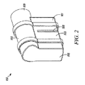
図1−4には、OPEP装置100の、前方斜視図、後方斜視図、前方断面斜視図、分解図がそれぞれ示されている。説明のために、図3においては、OPEP装置100の内部構成要素が省略されている。OPEP装置100は概して、ハウジング102、チャンバー吸気口104、第1のチャンバー排気口106、第2のチャンバー排気口108(図2及び7に最もよく示されている)、及びチャンバー吸気口104と流体連通するマウスピース109を備える。図1−4においては、マウスピース109はハウジング102と一体に形成されているように示されているが、マウスピース109は、理想的な動作条件を維持するように、取り外して、大きさや形状が異なるマウスピース109と置き換え可能とすることも想定される。概して、ハウジング102及びマウスピース109は、ポリマーのような耐久性のあるどのような材料によっても構成することができる。そのような材料の一つとして、ポリプロピレンがある。または、アクリロニトリル・ブタジエン・スチレン(ABS)を使用することもできる。
FIGS. 1-4 show a front perspective view, a rear perspective view, a front sectional perspective view, and an exploded view of the
また、呼吸管やガスマスク(図示しない)のような他の又は追加のインターフェースをマウスピース109と流体連通させたり、ハウジング102に関連づけたりして取り付けることもできる。例えば、ハウジング102に、マウスピース109と流体連通する別体の一方向性吸息バルブ(図示しない)を有する吸入口(図示しない)を設けて、OPEP装置100の使用者が、呼息期間と吸息期間との間にOPEP装置100のマウスピース109を抜くことなく、この一方向性バルブを通して周囲空気を吸息するとともにチャンバー吸気口104を通して呼息することができるようにすることができる。加えて、エアロゾル療法とOPEP療法とを同時に実施するために、いかなる数のエアロゾル送達装置を、例えば上述の吸入口を介して、OPEP装置100に接続してもよい。吸気口が、使用者がOPEP装置100とともに使用しようとする特定のエアロゾル送達装置の排気口や異なるマウスピースに対して適合可能な、例えば弾性のあるアダプター又は他の柔軟なアダプターを有するようにできる。本明細書においては、エアロゾル送達装置との用語には、以下に限定するものではないが、例えば、任意のネブライザー、ソフトミスト吸入器、加圧定量吸入器、ドライパウダー吸入器、保持チャンバーと加圧定量吸入器との組み合わせ、又は同種のものが含まれる。適した市販のエアロゾル送達装置には、以下に限定するものではないが、AEROECLIPSE nebulizer、RESPIMAT soft mist inhaler、LC Sprint nebulizer、AEROCHAMBER PLUS holding chambers、MICRO MIST nebulizer、SIDESTREAM nebulizer、Inspiration Elite nebulizer、FLOVENT pMDI、VENTOLIN pMDI、AZMACORT pMDI、BECLOVENT pMDI、QVAR pMDI and AEROBID PMDI、XOPENEX pMDI、PROAIR pMDI、PROVENT pMDI、SYMBICORT pMDI、TURBOHALER DPI、及びDISKHALER DPIが含まれる。適したエアロゾル送達装置の記載は、米国特許第4,566,452号公報;第5,012,803号公報;第5,012,804号公報;第5,312,046号公報;第5,497,944号公報;第5,622,162号公報;第5,823,179号公報;第6,293、279号公報;第6,435、177号公報;第6,484,717号公報;第6,848,443号公報;第7,360,537号公報;第7,568,480号公報;及び第7,905,228号公報にあり、参照することによりこれらの全体を本明細書に組み入れる。
Also, other or additional interfaces, such as a breathing tube or gas mask (not shown), may be mounted in fluid communication with the
図1−4においては、ハウジング102は概して箱型である。しかし、いかなる形状のハウジング102を使用することもできる。さらに、チャンバー吸気口104、第1のチャンバー排気口106、及び第2のチャンバー排気口108は、複数(すなわち、2つ以上)の円形通路または直線状長穴のような、いかなる形状または一連の形状とすることができる。さらに重要なことには、当然のことながら、チャンバー吸気口104、第1のチャンバー排気口106、及び第2のチャンバー排気口108の断面形状は、後述する理想的な動作条件に影響を与える要因のほんの一部に過ぎない。
In FIGS. 1-4, the
好ましくは、ハウジング102は、理想的な動作条件を維持するために、それに含まれる構成要素が定期的にアクセスされ、清掃され、交換され、または再構成されるように、開けることができる。そのため、ハウジング102は、図1−4において、前方部分101、中間部分103、及び後方部分105を有するものとして示されている。前方部分101、中間部分103、及び後方部分105は、OPEP装置100がOPEP療法を適切に施すのに十分な程度の密封を相互部分間に形成するように、スナップフィットや圧入などのようなあらゆる適当な手段によって、互いに取り外し可能に取り付けられてもよい。
Preferably, the
図3に示すように、破線で示されている呼気流路110は、マウスピース109と、第1のチャンバー排気口106及び第2のチャンバー排気口108(図7)とのうちの少なくとも一つとの間に形成される。より具体的には、呼気流路110は、マウスピース109の部分から始まり、チャンバー吸気口104を通り、そして第1のチャンバー114すなわち入口チャンバー内に入る。第1のチャンバー114において、呼気流路は、180度曲がり、チャンバー通路116を通り、そして第2のチャンバー118すなわち出口チャンバー内に入る。第2のチャンバー118において、呼気流路110は、第1のチャンバー排気口106及び第2のチャンバー排気口108のうちの少なくとも一つを通って、OPEP装置100を出る。このようにして、呼気流路110は「折り返し」、すなわち、チャンバー吸気口104と第1のチャンバー排気口106及び第2のチャンバー排気口108のうちの少なくとも一つとの間において長手方向で反転される。しかし、破線で示される呼気流路110は例示的なものであり、OPEP装置100内に吐かれた空気が、マウスピース109又はチャンバー吸気口104から第1のチャンバー排気口106又は第2のチャンバー排気口108にまで進む際に、如何なる方向や経路にも流れうることは、当業者には当然のことであろう。
As shown in FIG. 3, the
図3は、OPEP装置100のハウジング102に関連したいくつかの他の特徴部を示している。例えば、押え部122は、後述するように、制限部材130(図5)が間違った方向に開くことを防止しており、制限部材130を収容する形状とされた座部124は、チャンバー吸気口104の周りに形成され、上部軸受部126と下部軸受部128とがハウジング102内に形成されてその間に回転可能に取り付けられた軸を収容するようにされている。一つ又は複数のガイド壁120が、第2のチャンバー118内に配置されていて、呼気を呼気流路110に沿って案内する。
FIG. 3 illustrates some other features associated with the
図5−7には、OPEP装置100の断面斜視図がその内部構成要素とともに示されている。OPEP装置100の内部構成要素は、制限部材130と、羽根132と、任意的な可変ノズル136とを備える。図示のように、制限部材130と羽根132とは、上部軸受部126と下部軸受部128との間に回転可能に取り付けられた軸134によって動作可能に連結されており、制限部材130と羽根132とが軸134の周りで一緒に回転可能となるようになっている。より詳細な点は後述するが、可変ノズル136は、そこを通る呼気の流れに応じてサイズが大きくなるようにされたオリフィス138を有する。
FIG. 5-7 shows a cross-sectional perspective view of the
図4−6はさらに、ハウジング102内の第1のチャンバー114及び第2のチャンバー118の分割された部分を示している。上述のように、チャンバー吸気口104は第1のチャンバー114への入り口を形成している。制限部材130は、チャンバー吸気口104の周囲の座部124に対して第1のチャンバー114の中側に配置されて、チャンバー吸気口104を通る呼気流路110に沿った呼気の流れが制限される閉止位置と、チャンバー吸気口104を通る呼気の流れがあまり制限されない開放位置との間で移動可能となっている。同様に、任意選択の可変ノズル136は、第1のチャンバー114に入った呼気の流れが可変ノズル136のオリフィス138を通って第1のチャンバー114から出るように、チャンバー通路116の周り又は中に配置されている。可変ノズル136のオリフィス138を通って第1のチャンバー114に入った呼気は、羽根132とガイド壁120とによって占められたハウジング102内における空間によって形成される第2のチャンバーに入る。羽根132の位置に応じて、呼気は、その後、第1のチャンバー排気口106と第2のチャンバー排気口108とのうちの少なくとも一方を通って第2のチャンバー118から出ることができる。
FIGS. 4-6 further illustrate a split portion of the
図8−14は、OPEP装置の内部構成要素100をより詳細に示す。まず図8−9を見ると、前方斜視図と後方斜視図とによって、軸134によって羽根132に動作可能に接続された制限部材130が示されている。制限部材130及び羽根132は、制限部材130が回転することによって羽根132が対応して回転し、またその逆も生じるように、軸134の周りで回転可能とされている。ハウジング102と同様に、制限部材130及び羽根132は、ポリマーのような耐久性のあるどのような材料によっても作製することができる。好ましくは、それらは、低収縮、低摩擦のプラスチックで構成される。そのような材料の一つとして、アセタールがある。
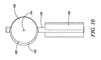
8-14 show the
図示のように、制限部材130、羽根132、及び軸134は、一体の部材として形成される。制限部材130は概して円板状であり、羽根132は平面である。制限部材130は、軸134からずれている略円形の面140と、チャンバー吸気口104の周りに形成された座部124に係合する形状とされた、傾斜すなわち面取りをした縁142とを有する。このように、制限部材130は、チャンバー吸気口104を通る呼気の流れを実質的に密封して制限する閉止位置において座部124に係合するように、軸134によって形成される回転軸線の周りでチャンバー吸気口104に対して動くようにされている。しかし、制限部材130及び羽根132は、それらが、理想的な動作条件を維持するように選択された、異なる形状、大きさ、又は重さの制限部材130又は羽根132と独立して交換可能であるように、適当な手段によって連結される別々の構成要素として形成されてもよいことが想定される。例えば、制限部材130や羽根132は、一つ又は複数の起伏のある表面を有していてもよい。または、制限部材130はバタフライバルブによって構成されていてもよい。
As shown, the limiting
図10には、制限部材130及び羽根132の正面図が示されている。上述のように、制限部材130は軸134からずれた略円形の面140を備える。制限部材130はさらに、閉止位置と開放位置との間の制限部材130の動きを容易にするように設計された第2のずれを有する。より具体的には、制限部材130の面140の中心点144が、放射方向でのずれと、軸134すなわち回転軸線とによって形成される平面からずれている。言い換えると、制限部材130の面140の表面積のうち軸134の一方の側の部分が、軸134の他方の側の部分に比べて、より大きくなっている。呼気により生ずるチャンバー吸気口104における圧力が、制限部材130の面140に作用する力をもたらす。制限部材130の面140の中心点144が上述のようにずれているので、その結果として生じる力の差により、軸134周りでのトルクが生じる。詳細は後述するが、このトルクが閉止位置と開放位置との間における制限部材130の動きを促す。
FIG. 10 shows a front view of the restricting
図11には、制限部材130及び羽根132の頂面図が示されている。図示のように、羽根132は制限部材130の面140に対して75°の角度で軸134に取り付けられている。羽根132の角度は、上述のように理想的な動作条件を維持するように選択的に調整されることが想定されるが、好ましくは、60°から80°の間に維持される。また好ましくは、OPEP装置100が完全に組み立てられて制限部材130が閉止位置にあるときに、可変ノズル136の中心線と羽根132との間の角度が10°から25°の間となるように、羽根132及び制限部材130が構成される。また、その構成に関わらず、制限部材130と羽根132との組み合わせが、軸134すなわち回転軸線上に重心を有するのが好ましい。本明細書の開示の全体からすれば、羽根132の角度は、ハウジング102の大きさや形状によって制限されて、羽根132及び制限部材130の全回転の概して半分より小さくなることは当業者にとって明らかである。
FIG. 11 shows a top view of the restricting
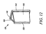
図12及び図13には、可変ノズル136の前方斜視図及び後方斜視図が、そこを通る呼気の流れがない状態で示されている。概して、可変ノズル136は、頂部と底部の壁146、側壁148、及びそれらの間に形成されたV字スリット150を有する。図示のように、可変ノズルは概してダックビル型バルブのような形をしている。しかし、他の形状や大きさのノズルやバルブを使用することも当然に可能である。可変ノズル136は、ハウジング102内において第1のチャンバー114と第2のチャンバー118との間に可変ノズル136を取り付けるように構成されたリップ部152を有していてもよい。可変ノズル136は、シリコーンなどの適度な柔軟性を有するどのような材料によって構成又は成形されていてもよく、好ましくは、0.50から2.00ミリメートルの厚さの壁と、0.25から1.00ミリメートルの幅、又は製造能力によってはより小さい幅のオリフィスとを有する。
12 and 13 show a front perspective view and a rear perspective view of the
上述のように、可変ノズル136は、OPEP装置100の動作上、任意のものである。OPEP装置100は、チャンバー通路116と可変ノズル136との両方を省略して、単一チャンバーの形態とすることも当然に可能である。OPEP装置100は、可変ノズル136なしでも機能はするが、可変ノズル136を備えた状態で動作すると、OPEP装置100の性能は呼気流量のより広い範囲に亘って向上する。可変ノズル136がないときのチャンバー通路116、または可変ノズル136が含まれるときの可変ノズル136のオリフィス138は、増速した呼気の噴流を生じさせる役目を果たす。以下で詳細に説明するように、第2のチャンバー118に流入する呼気の速度が増加することで、呼気によって羽根132に加えられる力が比例的に増加し、そして、軸134周りでのトルクが増加するが、これら全てが理想的な動作条件に影響を与える。
As described above, the
可変ノズル136なしの状態では、第1のチャンバー114と第2のチャンバー118との間のオリフィスは、チャンバー通路116の大きさ、形状、及び断面積に従って決定され、それらは、ハウジングの中間部分103や後方部分105を交換するなど、任意の適切な手段によって選択的に調整することができる。一方で、可変ノズル136がOPEP装置100内に含まれる場合には、第1のチャンバー114と第2のチャンバー118との間のオリフィスは、可変ノズル136のオリフィス138の大きさ、形状、及び断面積によって形成され、それらは呼気の流量や第1のチャンバー114内の圧力に応じて変化する。
Without the
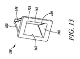
図14には、可変ノズル136の前方斜視図が、そこを通る呼気の流れがある状態で、示されている。図14に示す可変ノズル136の一つの特徴は、オリフィス138がそこを通る呼気の流れに応じて開いた際にオリフィス138の断面形状が略長方形に維持され、それにより、OPEP療法の施療中において可変ノズル136を第1のチャンバー114(図3、図5)から第2のチャンバー118に向かって通過するときの圧力降下がより小さくなることにある。流量が増加しているときの、可変ノズル136のオリフィス138の略一貫した長方形形状は、頂部及び底部の壁146と側壁148との間に形成されるV字スリット150によって実現され、V字スリット150は側壁148が無制限に曲がるようにするのに役立つ。V字スリット150は、そこを通る呼気の漏れを最小限にするためにできる限り細くされるのが好ましい。例えば、V字スリット150の幅はおよそ0.25ミリメートルであるが、製造能力によっては、0.10から0.50ミリメートルの範囲内とすることもできる。V字スリット150を通って漏れる呼気は、最終的には第2のチャンバー118内でハウジング102から突出しているガイド壁120によって、呼気流路に沿うように向けられる。
FIG. 14 shows a front perspective view of the
当然のことながら、可変ノズル136の形状や材質を含む多数の要因が、可変ノズル136のOPEP装置100の性能に対する影響に関係している。単なる一例として、呼気流量15リットル/分で10から13Hzという目標振動圧力周波数を実現するために、一実施形態においては、1.0×20.0ミリメートルの通路すなわちオリフィスを利用することができる。しかし、呼気流量が増加するとこの実施形態における振動圧力の周波数も増加するが、それは目標周波数に比べて急すぎる変化率となる。呼気流量45リットル/分で18から20Hzという目標振動圧力周波数を実現するために、同実施形態で3.0×20.0ミリメートルの通路すなわちオリフィスを利用することができる。このような関係性は、通路すなわちオリフィスが、可変ノズル136を隔てた圧力の降下を制限するために、呼気流量が増加したときに断面積が拡大することが望ましいことを明示している。
Of course, many factors, including the shape and material of the
図15A−Cには、OPEP装置100の頂面透視図によって、OPEP装置100の動作の典型的な図が示されている。具体的には、図15Aは、初期位置、すなわちチャンバー吸気口104を通過する呼気の流れが制限されて羽根132が第1位置にあって呼気の流れを第1のチャンバー排気口106に向ける閉止位置、にある制限部材130を示している。図15Bは、チャンバー吸気口104を通過する呼気の流れがあまり制限されなくなり、羽根132が可変ノズル136から流出する呼気の噴流に対してまっすぐに整列した、部分的な開放位置にある制限部材130を示している。図15Cは、チャンバー吸気口104を通過する呼気の流れがさらに制限されなくなり、羽根132が第2位置となって、呼気の流れを第2のチャンバー排気口108に向ける開放位置にあるときの制限部材130を示している。
当然のことながら、後述するサイクルはOPEP装置100の動作の単なる典型例であり、また多数の要因がOPEP装置100の動作に影響を与え、その結果、記載されたサイクルから逸脱することもある。しかし、OPEP装置100の動作中、制限部材130及び羽根132は、概して図15Aに示す位置と15Cに示す位置との間で往復動する。
15A-C show typical views of the operation of the
It will be appreciated that the cycles described below are merely exemplary of the operation of the
OPEP療法の施療中、制限部材130及び羽根132は、最初、図15Aに示すように位置するかもしれない。この位置において、制限部材130は閉止位置にあり、チャンバー吸気口104を通過して呼気流路に沿う呼気の流れが実質的に制限される。そのため、使用者がマウスピース108内に息を吐くと、チャンバー吸気口104における呼気圧力が上昇する。チャンバー吸気口104における呼気圧力が上昇すると、それに対応する制限部材130の面140に作用する力が大きくなる。上述のように、面140の中心点144が径方向のずれと軸134とによって形成される平面からずれているので、その結果として生じる合力が軸周りでの負のトルク、すなわち開放トルクを生み出す。これにより、開放トルクが制限部材130を回転させて開放するように付勢して、呼気が第1のチャンバー114に入るようにし、また、羽根132をその第1位置から離れるように付勢する。制限部材130が開き、呼気が第1のチャンバー114に導入されると、チャンバー吸気口104での圧力が降下して制限部材の面140に作用する力が小さくなり始めて、制限部材130を開くように付勢しているトルクが小さくなり始める。
During OPEP therapy, the
呼気がチャンバー吸気口104を通過して第1のチャンバー114に流入し続けると、呼気は、第1のチャンバー114と第2のチャンバー118との間に配置されたチャンバー通路116に到達するまで、ハウジング102によって呼気流路110に沿って案内される。もしOPEP装置100が可変ノズル136なしで動作されると、呼気は、断面積の減少によりチャンバー通路116を加速して進み呼気の噴流を形成する。同様に、もしOPEP装置100が可変ノズル136ありで動作されると、呼気は、可変ノズル136のオリフィス138を加速して進み、オリフィス138を通過する圧力が可変ノズル136の側壁148を外側に曲げ、それによりオリフィス138の大きさが増加し、また結果としてそこを通る呼気の流れも増加する。いくらかの呼気が可変ノズル136のV字スリット150から漏れている程度においては、その呼気はハウジング102内に突出するガイド壁120によって呼気の噴流に戻されて、呼気流路に沿って案内される。
As exhaled air continues to flow through
次に、呼気が可変ノズル136やチャンバー通路116を通過して第1のチャンバー114から出て第2のチャンバー118に入ると、呼気は羽根132によってハウジング102の前方部分101に向けて案内され、逆方向に向けられた後に開放した第1のチャンバーの排気口106を通ってOPEP装置100から出る。ハウジング102の前方部分101に向かって呼気の方向が変化することによって、ハウジング102の前方部分101の近くでの第2のチャンバー118内の圧力が蓄積し、これにより、隣接する羽根132への力が生じ、軸134周りの追加的な負のトルクすなわち開放トルクが生じる。制限部材130の面140及び羽根132に作用する力によって軸134の周りで生じる複合した開放トルクが、制限部材130及び羽根132を図15Aに示す位置から図15Bに示す位置に向かって軸134周りで回転させる。
Next, when exhaled air exits the
制限部材130及び羽根132が図15Bに示す位置に回転すると、羽根132は可変ノズル136又はチャンバー通路116から出る呼気の噴流を横断する。最初、可変ノズル136又はチャンバー通路116からの呼気の噴流は羽根132上に力を生じさせ、その力が、羽根132、軸134、及び制限部材130の運動量とともに、羽根132及び制限部材130を図15Cに示す位置にまで推進する。しかし、図15Bに示す位置のあたりでは、可変ノズル136からの呼気によって羽根132に作用する力が、負のトルクすなわち開放トルクから正のトルクすなわち閉止トルクへと切り替わる。より具体的には、呼気が可変ノズル136を通過して第1のチャンバー114から出て第2のチャンバー118に入ると、呼気は羽根132によってハウジング102の前方部分101に向けて案内され、逆方向に向けられた後に開放した第2のチャンバーの排気口108を通ってOPEP装置100から出る。ハウジング102の前方部分101に向かって呼気の方向が変化することによって、ハウジング102の前方部分101の近くでの第2のチャンバー118内での圧力が蓄積し、これにより、隣接する羽根132への力が生じ、軸134周りでの正のトルクすなわち閉止トルクが生じる。羽根132及び制限部材130が図15Cに示す位置に近づくように移動し続けると、第2のチャンバー118内のハウジング102の前方部分101の近くに蓄積する圧力及びこれによる軸134周りでの正のトルクすなわち閉止トルクが増加し続けて、呼気流路110に沿ってチャンバー吸気口104を通過する呼気の流れがあまり制限されなくなる。その一方で、制限部材130上に作用する力による軸134周りでのトルクも図15Bに示す位置のあたりで負のトルクすなわち開放トルクから正のトルクすなわち閉止トルクに切り替わるが、その大きさは、制限部材130及び羽根132が図15Bに示す位置から図15Cに示す位置に回転するときには基本的には無視できるほどのものである。
When the
羽根132及び制限部材130は、図15Cに示す位置に到達した後には、軸134周りでの正のトルクすなわち閉止トルクの増加によって、逆向きに図15Bに示す位置に向かって戻るように回転し始める。羽根132及び制限部材130が図15Bに示す位置に近づき、チャンバー吸気口104を通る呼気の流れがだんだんと制限されていくと、軸134周りでの正のトルクすなわち閉止トルクが減少し始める。制限部材130及び羽根132が図15Bに示す位置に到達すると、羽根132が可変ノズル136又はチャンバー通路116から出る呼気の噴流を横断し、これにより羽根132上への力が、羽根132、軸134、及び制限部材130の運動量とともに、羽根132及び制限部材130を図15Aに示す位置にまで戻すように推進する。制限部材130及び羽根132が図15Aに示す位置にまで戻った後は、チャンバー吸気口104を通過する呼気の流れが制限され、そして、上述のサイクルが繰り返される。
After reaching the position shown in FIG. 15C, the
当然のことながら、一回の呼気期間中に、上述のサイクルは何度も繰り返される。このようにして制限部材130が、チャンバー吸気口104を通過する呼気の流れが制限される閉止位置とチャンバー吸気口104を通過する呼気の流れがあまり制限されなくなる開放位置との間で繰り返し動くことで、OPEP装置100の使用者に振動する背圧が伝わり、OPEP療法が施される。
Of course, during one expiration period, the above-described cycle is repeated many times. In this way, the restricting
ここで図16−17を見ると、別の実施形態に係る可変ノズル236が示されている。可変ノズル236は、OPEP装置100において、上述の可変ノズル136に替えて使用できる。図16−17に示すように、可変ノズル236は、オリフィス238、頂部及び底部の壁246、側壁248、及びリップ部252を有し、該リップ部252は、可変ノズル136と同様に、OPEP装置100のハウジング内において第1のチャンバー114と第2のチャンバー118との間に可変ノズル236を取り付けるように構成されている。図12−13に示す可変ノズル136と同様に、この可変ノズル236は、シリコーンなどの適度な柔軟性を有するどのような材料によって構成又は成形されていてもよい。
Turning now to FIGS. 16-17, a
OPEP療法の施療中に、可変ノズル236のオリフィス238がそこを通る呼気の流れに応じて開いた際に、オリフィス238の断面形状は略長方形に維持され、それにより、可変ノズル236を第1のチャンバー114から第2のチャンバー118に向かって通過するときの圧力降下がより小さくなる。流量が増加しているときの、可変ノズル236のオリフィス238の略一貫した長方形形状は、頂部及び底部の壁246に形成された薄くて、折り目の付けられた壁によって実現され、これにより側壁248がより容易に且つより小さい抵抗で曲がることを可能とする。当該実施形態のさらなる利点として、呼気が可変ノズル236のオリフィス238を通って流れている間に、例えば、図12−13に示す可変ノズル136のV字スリット150を介した漏れのような、頂部及び底部の壁246からの外部への漏れがないことがある。
During the OPEP therapy, when the
ある応用においては正の呼気圧力だけ(振動なし)が望まれ、そのような場合にはOPEP装置100は、制限部材130なしとし、固定されたオリフィスまたは手動調整可能なオリフィスを代わりに使って動作させてもよいことは当業者にとって当然であろう。正の呼気圧力の実施形態は、望ましい範囲内において背圧を比較的に一定に維持するために、可変ノズル136又は可変ノズル236を備えてもよい。
第二の実施形態
In some applications, only positive expiratory pressure (no vibration) is desired, in which case the
Second embodiment
ここで図18−19を見ると、第二の実施形態に係るOPEP装置200の前方斜視図及び後方斜視図が示されている。OPEP装置200の構成及び動作は、OPEP装置100と同様である。しかし、図20−24に最もよく示されるように、OPEP装置200はさらに、ハウジング202と制限部材230とに対するチャンバー吸気口204の相対的位置を変更するようにされた調整機構253を備え、この調整機構253に対して操作可能に取り付けられた羽根232の回転範囲を変更するようになっている。それによって、以下で説明するように、使用者は、ハウジング202を開けたりOPEP装置200の構成要素を分解したりすること無く、OPEP装置200によって施療されるOPEP療法の周波数と振幅との両方を簡便に調整することが可能となる。
18-19, a front perspective view and a rear perspective view of the
OPEP装置200は、概して、ハウジング202、チャンバー吸気口204、第1のチャンバー排気口206(図23、図32)、第2のチャンバー排気口208(図23、図32)、及びチャンバー吸気口204と流体連通するマウスピース209を備える。OPEP装置100と同様に、前方部分201、中間部分203、及びハウジング202の後方部分205は、理想的な動作条件を維持するために、それに含まれる構成要素が定期的にアクセスされ、清掃され、交換され、または再構成されるように、分解可能である。OPEP装置は、後述するように、調整ダイヤル254も有する。
OPEP装置100に関連して上述したように、OPEP装置200は、エアロゾル送達装置などの他の又は追加のインターフェースとともに使用できるようにしてもよい。これに関連して、OPEP装置200は、マウスピース209とチャンバー吸気口204とに流体連通した吸入口211(図19、図21、図23)を備える。上述の通り、吸入口が一方向性バルブ(図示しない)を有していて、OPEP装置200の使用者が、吸息期間と呼息期間との間にOPEP装置200のマウスピース209を抜くことなく、この一方向性バルブを通して周囲の空気を吸息し且つチャンバー吸気口204を通して呼息することができるようにすることができる。加えて、上述のエアロゾル送達装置を吸入口211に取り付けて、エアロゾル療法とOPEP療法との同時施療を行うようにすることもできる。
As described above in connection with
OPEP装置200の分解図が図20に示されている。上述のハウジングの構成要素に加えて、OPEP装置200は、ピン231によって羽根232に動作可能に接続された制限部材230、調整機構253、及び可変ノズル236を備える。図21の断面図に示すように、OPEP装置200の使用中、可変ノズル236は中間部分203とハウジング202の後方部分205との間に位置し、調整機構253、制限部材230、及び羽根232は組み立て体を形成している。
An exploded view of the
図21−23には、いくつかのOPEP装置200の断面斜視図が示されている。OPEP装置100と同様に、破線によって示される呼気流路210は、マウスピース209と、第1のチャンバー排気口206と第2のチャンバー排気口208(図23、図32)とのうちの少なくとも一方との間に形成される。呼気流路210は、一方向性バルブ(図示しない)や吸入口211に取り付けられたエアロゾル送達装置(図示しない)によって、動作中に制限部材230によって閉じられたり閉じられなかったりするかもしれないが、マウスピース209から始まりチャンバー吸気口204に向けられる。チャンバー吸気口204を通過後、呼気流路210は、第1のチャンバー214に入り、そして可変ノズル236に向かって180°曲がる。可変ノズル236のオリフィス238を通過後、呼気流路210は第2のチャンバー218に入る。第2のチャンバー218において、呼気流路210は、第1のチャンバー排気口206と第2のチャンバー排気口208とのうちの少なくとも一方を通ってOPEP装置200から出る。破線によって示される呼気流路210は例示的なものであり、OPEP装置200内に吐かれた空気が、マウスピース209又はチャンバー吸気口204から第1のチャンバー排気口206又は第2のチャンバー排気口208までジグザグに進む際に、如何なる方向や経路にも流れ得ることは、当業者には当然のことであろう。
21-23 show cross-sectional perspective views of some
図24−25を参照すると、OPEP装置200の調整機構253の前方及び後方からの斜視図が示されている。概して、調整機構253は、調整ダイヤル254、軸255、及びフレーム256を備える。後述するように、突起258が調整ダイヤルの後方面260に配置されていて、使用者による調整機構253の選択的回転を制限するようになっている。軸255は、ハウジング200(図21、図28−29)に形成された上部及び下部軸受部226、228内に嵌合するようにされたキー作用部262を有する。軸は、制限部材230と羽根232とを動作可能に連結するためのピン231を受け入れるようにされた軸方向穴264をさらに有する。図示のように、フレーム256は、球状であり、以下で説明するように、ハウジング202に対して回転すると同時に、ハウジング202とフレーム256との間にOPEP療法の施療を可能とするのに十分なだけの密封を形成するように構成されている。フレーム256は、制限部材230を収容するようにされた座部224によって形成される円形開口を有する。使用時、円形開口はチャンバー吸気口204として機能する。フレーム256は、制限部材230が間違った方向に開くのを防止するための止め部222をさらに有する。
Referring to FIGS. 24-25, front and rear perspective views of the
図26には、制限部材230及び羽根232の前方斜視図が示されている。制限部材230及び羽根232のデザイン、材料、及び構成は、OPEP装置100に関して上述したものと同様である。しかし、OPEP装置200における制限部材230及び羽根232は、調整機構253の軸255における軸方向穴264に挿通されるようにされたピン231によって動作可能に連結される。ピン231は、例えば、ステンレス鋼によって構成される。このようにして、制限部材230の回転が羽根232の対応する回転を生じさせ、またその逆も生じさせる。
FIG. 26 is a front perspective view of the
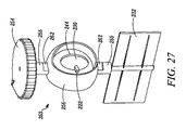
図27には、制限部材230と羽根232とが組み付けられた調整機構253の前方斜視図が示されている。この構成においては、制限部材230が、チャンバー吸気口204を通る呼気流路210に沿う呼気の流れが制限される閉止位置(図示の通り)と、チャンバー吸気口204を通る呼気の流れがあまり制限されない開放位置(図示しない)との間で、フレーム256と座部224とに対して回転可能であることが分かる。上述のように、羽根232は、軸255を通って延在するピン231によって制限部材230に動作可能に接続されて、制限部材230と一緒に動くようにされている。制限部材230及び羽根232は、以下で説明するように、OPEP装置200のハウジング202内において回転可能な調整機構253によって支持されていることも分かる。
FIG. 27 is a front perspective view of the
図28及び図29A−Bは、OPEP装置200のハウジング202内に取り付けられた調整機構253を示す部分断面図である。図28に示すように、調整機構253は、制限部材230及び羽根232とともに、上部及び下部軸受部226、228の周りで回転可能にハウジング200に取り付けられており、これにより使用者が調整ダイヤル254を使って調整機構253を回転させることができるようにしている。図29A−29Bはさらに、ハウジング202の下部軸受部228内に調整機構253を取り付けてロックするときの工程を示している。より具体的には、軸255のキー作用部262が、図29Aに示すように、ハウジング202に形成された回転ロック部266と整列してそこを通して挿入される。軸255のキー作用部262が回転ロック部266を通して挿入されると、軸255は90°回転されてロック位置となるが、回転自在なままとなる。調整機構253も同様に、上部軸受部226内に取り付けられてロックされる。
FIGS. 28 and 29A-B are partial cross-sectional views showing the
ハウジング202及びOPEP装置200の内部構成要素が組み立てられると、軸255の回転は、回転ロック部266のロック位置内に軸255が保持されるように制限される。図30のOPEP装置200の正面図に示すように、2つの止め部268、288がハウジング202上に配置されて、使用者が調整ダイヤル254を所定の位置に回転させたときにそれら止め部268、288が調整ダイヤル254の後方面260に形成された突起258に係合するようになっている。説明のために図30においては、OPEP装置200が、ハウジング202から開口部269を通って延在することになる調整ダイヤル254又は調整機構253なしで示されている。このようにして、調整ダイヤル254、調整機構253、及び軸255のキー作用部262の回転が適切に制限される。
When the
図31には、ハウジング200内に取り付けられた調整機構253の部分断面図が示されている。上述のように、調整機構253のフレーム256は、球状であり、ハウジング202に対して回転すると同時に、ハウジング202とフレーム256との間にOPEP療法の施療を可能とするのに十分なだけの密封を形成するように構成されている。図31に示すように、ハウジング202から延在する柔軟性のある筒状部271が、フレーム256の一部を完全に取り囲んで、密封縁270を形成している。ハウジング202及び制限部材230と同様に、柔軟性のある筒状部271及びフレーム256は、低収縮、低摩擦のプラスチックから構成することができる。そのような材料の一つとして、アセタールがある。このようにして、密封縁270はフレーム256と全360°接触して、調整部材253の許容回転量の全範囲内において密封を形成する。
FIG. 31 is a partial cross-sectional view of the
ここでOPEP装置200の選択的調整を、図32A−B、33A−B、及び34A−Bを参照して説明する。図32A−BはOPEP装置200の部分断面図であり、図33A−BはOPEP装置200の調整機能を示す図であり、図34A−BはOPEP装置200の頂面透視図である。OPEP装置100に関連して上述したように、好ましくは、OPEP装置200が完全に組み立てられて制限部材230が閉止位置にあるときに、可変ノズル236の中心線と羽根232との間の角度が10°から25°の間となるように、羽根232及び制限部材230が構成される。しかし、当然のことながら、OPEP装置200の調整機能はここに記載したパラメータに限定されるものではなく、理想的な動作条件内においてOPEP療法を施療するために如何なる構成が選択されてもよい。
Here, the selective adjustment of the
図32Aは可変ノズル236の中心線からの角度が10°であるときの羽根232を示し、一方、図32Bは可変ノズル236の中心線からの角度が25°であるときの羽根232を示している。図33Aは、制限部材230が閉止位置にあるときに可変ノズル236の中心線と羽根232との間の角度が10°となるようにするための、フレーム256(透視図で示す)の可変ノズル236に対する必要な配置を示す。一方で、図33Bは制限部材230が閉止位置にあるときに可変ノズル236の中心線と羽根232との間の角度が25°となるようにするための、フレーム256(透視図で示す)の可変ノズル236に対する必要な配置を示す。
FIG. 32A shows
図34A−Bを参照すると、OPEP装置200の側面透視図が示されている。図34Aに示す構成は図32A及び図33Aに示す図に対応し、制限部材230が閉止位置にあるときに可変ノズル236の中心線と羽根232との間の角度が10°となっている。一方で、図34Bは、図32B及び図33Bに示す図に対応し、制限部材230が閉止位置にあるときに可変ノズル236の中心線と羽根232との間の角度が25°となっている。要するに、調整部材253のフレーム256は図34Aに示す位置から図34Bに示す位置にまで反時計周りに15°回転され、それにより羽根232の許容回転量も大きくなっている。
Referring to FIGS. 34A-B, a side perspective view of the
このようにして使用者は、調整ダイヤル254を回転させて、制限部材230及びハウジング202に対するチャンバー吸気口204の向きを選択的に調整することができる。例えば、使用者は、調整ダイヤル254を回転させて、それによりフレーム256を図34Aに示す位置に向かって回転させることにより、OPEP装置200によって施療されるOPEP療法の周波数及び振幅を増加させることができる。代わりに、使用者が、調整ダイヤル254を回転させて、それによりフレーム256を図34Bに示す位置にまで回転することによって、OPEP装置200によって施療されるOPEP療法の周波数及び振幅を減少させることもできる。また、例えば図18及び図30に示すように、使用者がOPEP装置200を適切な構成に設定するのを補助するためにしるしを設けてもよい。
In this manner, the user can selectively adjust the direction of the
OPEP装置800を参照して後述する動作条件と同様な動作条件をOPEP装置200に係るOPEP装置に対して実現可能とすることもできる。
第3の実施形態
The same operating conditions as those described below with reference to the OPEP apparatus 800 can be realized for the OPEP apparatus according to the
Third embodiment
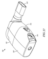
図35−37には、別の実施形態に係るOPEP装置300が示されている。OPEP装置300は、選択的に調整可能である点においてOPEP装置200と同様である。図35、図37、図40、及び図49によく示されるように、OPEP装置300は、OPEP装置200と同様に、ハウジング302と制限部材330とに対するチャンバー吸気口304の相対的位置を変更するようにされた調整機構353を備え、該調整機構353に対して操作可能に取り付けられた羽根332の回転範囲を変更するようになっている。OPEP装置200に関連して上述したように、使用者は、ハウジング302を開けたりOPEP装置300の構成要素を分解したりすること無く、OPEP装置300によって施療されるOPEP療法の周波数と振幅との両方を簡便に調整することが可能である。OPEP装置300を使用したOPEP療法の施療は、別の面では、OPEP装置100に関して上述したものと同様である。
35 to 37 show an
OPEP装置300は、前方部分301、後方部分305、及び内部ケーシング303を有するハウジング302を備える。上述のOPEP装置と同様に、前方部分301、後方部分305、及び内部ケーシング303は、理想的な動作条件を維持するために、それに含まれる構成要素が定期的にアクセスされ、清掃され、交換され、または再構成されるように、分解可能である。例えば図35−37に示すように、ハウジング302の前方部分301及び後方部分305は、スナップフィット係合によって取り外し可能に連結されている。
The
OPEP装置300の構成要素が図38の分解図にさらに示されている。概して、OPEP装置300は、前方部分301、後方部分305、及び内部ケーシング303に加えて、マウスピース309、吸入口311、それらの間に配置された一方向性バルブ384、調整機構353、制限部材330、羽根332、及び可変ノズル336を備える。
The components of the
図39−40に見られるように、内部ケーシング303は、ハウジング302内の前方部分301と後方部分305との間に嵌合され、第1のチャンバー314と第2のチャンバー318とを部分的に画定している。内部ケーシング303は、図41−42に示す斜視図及び斜視断面図においてより詳細に示されている。第1のチャンバー排気口306及び第2のチャンバー排気口308は、内部ケーシング303内に形成されている。内部ケーシング303の一端385は、可変ノズル336を受け入れるようにされていて、後方部分305と内部ケーシング303との間に可変ノズル336を維持する。調整機構353を支持するための上部軸受部326及び下部軸受部328は、内部ケーシング303内に少なくとも部分的に形成されている。OPEP装置200に関連して上述した柔軟性のある筒状部271及び密封縁270と同様に、内部ケーシング303も、調整機構353のフレーム356の周囲に係合するための密封縁370を有する柔軟性のある筒状部371を備える。
As seen in FIGS. 39-40, the
羽根332は、図43の斜視図においてより詳細に示されている。軸334は、羽根332から延在していて、制限部材330の穴365内の対応するキー溝部と係合して固定される。このようにして、軸334は、羽根332と制限部材330とが一緒に回転するように、羽根332を制限部材330に動作可能に連結する。
The
制限部材330は、図44−45の斜視図においてさらに詳細に示されている。制限部材330は、羽根332から延在している軸334を受け入れるためのキー穴365と、調整部材353の座部324に対する制限部材330の許容回転量を制限する止め部322とを有する。図46の正面図に示すように、制限部材330は、制限部材230と同様に、閉止位置と開放位置との間における制限部材330の動きを容易にするように設計されたずれをさらに有する。より具体的には、制限部材330の面340の表面積のうち軸334を受け入れるための穴365の一方の側の部分が、穴365の他方の側の部分に比べて、より大きくなるようにしている。制限部材130に関連して上述したように、このずれが軸334周りの開放トルクを呼息期間中に生じさせる。
調整機構353は、図47及び48の前方及び後方斜視図に、より詳細に示されている。概して、調整機構は、内部ケーシング303上に形成された柔軟性のある筒状部371の密封縁370と係合するようにされたフレーム356を備える。フレーム356の円形開口が、制限部材330を収容するような形状とされた座部324を形成している。この実施形態においては、座部324がチャンバー吸気口304も画定する。調整機構353は、OPEP装置300が完全に組み立てられたときに使用者が調整機構353及びチャンバー吸気口304の向きを選択的に調整できるようにするために、フレーム356からハウジング302を超える位置にまで延在するようにされた腕部354をさらに備える。調整機構353は、軸334を受け入れるための上部軸受部385及び下部軸受部386も有する。
The
羽根332、調整機構353、及び制限部材330の組み立て体が、図49の斜視図に示されている。上述のように、羽根332と制限部材330とは軸334によって動作可能に連結されており、羽根332の回転が制限部材330の回転を生じさせ、またその逆も生じさせる。それに対して、調整機構353、及びチャンバー吸気口304を形成する座部324は、羽根332及び制限部材330に対して軸334周りで回転するようにされている。このようにして使用者は、腕部354を回転させることで、制限部材330及びハウジング302に対するチャンバー吸気口304の向きを選択可能に調整できる。例えば、使用者は、時計周りの方向に腕部354を回転させて、それによりフレーム356を回転させることで、OPEP装置300によって施療されるOPEP療法の周波数及び振幅を増加させることができる。または、使用者は、反時計周りの方向に調整用の腕部354を回転させて、それによりフレーム356を回転させることで、OPEP装置300によって施療されるOPEP療法の周波数及び振幅を減少させることができる。また、例えば図35及び図37に示すように、使用者がOPEP装置300を適切な構成に設定するのを補助するために、ハウジング302にしるしを設けてもよい。
The assembly of the
図50−51の前方及び後方斜視図に、可変ノズル336がより詳細に示されている。OPEP装置300における可変ノズル336は、可変ノズル336が、内部ケーシング303の一端385(図41−42)内に嵌合されて後方部分305と内部ケーシング303との間に可変ノズル336を維持するようにされた基板387を有する点を除き、OPEP装置200に関連して上述した可変ノズル236と同様である。可変ノズル236と同様に、可変ノズル336及び基板387はシリコーンから形成することができる。
The
図52の前方斜視図に、一方向性バルブ384がさらに詳細に示されている。概して、一方向性バルブ384は、ハウジング302の前方部分301に取り付けるようにされた支持部388と、力や圧力が加わるとそれに応じて支持部388に対して曲がるか枢動するようにされたフラップ389とを備える。本明細書に開示する当該実施形態及び他の実施形態において、本開示の技術から逸脱することなく他の一方向性バルブを使用できることは、当業者には当然のことであろう。図39−40から分かるように、一方向性バルブ384は、ハウジング302内でマウスピース309と吸入口311との間に配置される。
The one-
OPEP装置100に関連して上述したように、OPEP装置300はエアロゾル送達装置などの他の又は追加のインターフェースとともに使用するようにすることができる。これに関連して、OPEP装置300は、マウスピース309と流体連通した吸入口311(図35−36、図38−40)を備える。上述のように、吸入口が別体の一方向性バルブ384(図39−40、図52)を有しており、吸息期間と呼息期間との間にOPEP装置300のマウスピース309を抜くことなく、この一方向性バルブ384を通して周囲の空気を吸息し且つチャンバー吸気口304を通して呼息することができるようにすることができる。加えて、上述の市販のエアロゾル送達装置を吸入口311に取り付けて、エアロゾル療法(吸息時)とOPEP療法(呼息時)との同時施療を行うようにすることもできる。
As described above in connection with
OPEP装置300と上述の構成要素とが、図39−40に示す断面図においてさらに説明されている。説明のために、図39の断面図はOPEP装置の全ての内部構成要素300を省略して示されている。
The
前方部分301、後方部分305、及び内部ケーシング303は組み立てられて第1のチャンバー314及び第2のチャンバー318を形成する。OPEP装置100と同様に、破線によって示された呼気流路310は、マウスピース309と、いずれも内部ケーシング303内に形成されている第1のチャンバー排気口306(図39−40、図42)と第2のチャンバー排気口308(図41)とのうちの少なくとも一方との間に形成されている。呼気流路310は、吸入口311及び一方向性バルブ348によって、動作中に制限部材330によって閉じられたり閉じられなかったりするかもしれないが、マウスピース309から始まりチャンバー吸気口304の方に向けられる。呼気流路310は、チャンバー吸気口304を通過後、第1のチャンバー314に入り、可変ノズル336に向かって180°曲がる。呼気流路310は、可変ノズル336のオリフィス338を通過後、第2のチャンバー318に入る。第2のチャンバー318内において、呼気流路310は、第2のチャンバー318から出て、第1のチャンバー排気口306と第2のチャンバー排気口308とのうちの少なくとも一方を通って最終的にハウジング302から出る。破線によって示された呼気流路310は例示的なものであり、OPEP装置300内に吐かれた空気が、マウスピース309又はチャンバー吸気口304から第1のチャンバー排気口306又は第2のチャンバー排気口308にまで進む際に、如何なる方向又は経路にも流れ得ることは、当業者には当然のことであろう。上述のように、OPEP装置300を使用したOPEP療法の施療は、別の面では、OPEP装置100に関して上述したものと同様である。
The
単なる例ではあるが、以下の動作条件又は動作特性が、調整ダイヤル354を周波数及び振幅を増加させるように設定したOPEP装置300に係るOPEP装置によってなされる。

OPEP装置用の圧力表示装置
By way of example only, the following operating conditions or characteristics may be provided by an OPEP device in accordance with
Pressure display for OPEP device
医療産業には低価格、人間工学的、小形で、携帯可能なOPEP装置用の圧力表示装置の解決策が不足している。例えば、ほとんどの商業的に入手可能な圧力計は管を使って接続することのできる大形の据え置き型の装置であり、扱いにくくて魅力がない。また、ほとんどの商業的に入手可能な圧力計は再使用できることを意図されており、このことは感染性疾患を伝染させる危険につながる。更に、既存の圧力計は、OPEP療法の施療中にOPEP装置で発生されるような振動圧力の読み取りと視覚的フィードバックを意図していない。そのような圧力計をOPEP装置とともに使用することは、圧力の読み取り出力の過剰な変動を引き起こし、当該装置の使用者またはその臨床医が正確なフィードバックを得ることを困難にする。 The medical industry lacks a low cost, ergonomic, compact, portable pressure indicator solution for OPEP devices. For example, most commercially available pressure gauges are large, stationary devices that can be connected using tubing, and are cumbersome and unattractive. Also, most commercially available pressure gauges are intended to be reusable, which leads to the risk of transmitting infectious diseases. Further, existing manometers do not contemplate the reading of oscillating pressure and visual feedback as generated by OPEP devices during the administration of OPEP therapy. The use of such a pressure gauge with an OPEP device causes excessive fluctuations in the pressure reading output, making it difficult for the user of the device or its clinician to get accurate feedback.
ここで説明する実施形態は、既存のOPEP装置と容易に一体化され、又、一人の患者での繰り返し使用に適した人間工学的な圧力表示装置を可能にする。更に、これらの実施形態は使用者に提供される視覚的フィードバックにおける振動を最小化するように構成され、その結果として圧力表示装置が圧力を読み取り可能な水準で表示することを可能とし、同時に、動的な視覚的フィードバックを提供して、OPEP装置がそれ自体の振動圧力を感知することで機能しているということを使用者に知らせる。 The embodiments described herein are easily integrated with existing OPEP devices, and also allow for an ergonomic pressure display suitable for repeated use on a single patient. Further, these embodiments are configured to minimize vibration in the visual feedback provided to the user, thereby enabling the pressure display to display pressure at a readable level, while at the same time It provides dynamic visual feedback to inform the user that the OPEP device is functioning by sensing its own oscillating pressure.
ここに記載された圧力表示装置の実施形態は、図35のOPEP装置と共に使用するものとして図示され記載されているが、当該圧力表示装置は他のOPEP装置と共に使用することにも適していることは理解されるであろう。例えば、本明細書に記載された他のOPEP装置の実施形態及び、米国特許第5,018,517号、第6,581,598号、第6,776,159号、第7,059,324号、第8,327,849号、第8,539,951号及び第8,485,179号に図示され記載されているOPEP装置を含み、ここに参照して全体を組み入れる。又、米国特許出願第13/489,894号及び第14/092,091号についても同様であり、ここに参照して全体を組み入れる。更に、在カナダTrudell Medical International of London社のAEROBIKA(登録商標)、在ミネソタ州Smiths Medical of St. Paul社のACAPELLA(登録商標)、在アラバマ州バーミンガムAxcan Scandipharm Inc.社のFLUTTER(登録商標)、在オハイオ州Curaplex of Dublin社のRC-CORONET(登録商標)など幾つもの市販のOPEP装置も含まれる。
圧力表示装置の第一の実施形態
Although the embodiment of the pressure indicator described herein is shown and described for use with the OPEP device of FIG. 35, the pressure indicator is also suitable for use with other OPEP devices. Will be understood. For example, illustrated in the other OPEP device embodiments described herein and in U.S. Patent Nos. Including the described OPEP device, which is hereby incorporated by reference in its entirety. The same applies to U.S. Patent Applications Nos. 13 / 489,894 and 14 / 092,091, which are hereby incorporated by reference in their entirety. In addition, AEROBICA (R) of Trudell Medical International of London, Canada, ACAPELLA (R) of Smiths Medical of St. Paul, Minnesota, Axell Scan Trade Mark of Birmingham, Alabama, Inc. A number of commercially available OPEP devices are also included, such as RC-CORONET® from Curaplex of Dublin, Ohio.
First embodiment of pressure display device
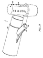
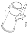
図53−56には第一の実施形態に係る圧力表示装置400が示されている。概して、圧力表示装置400は胴部402、胴部402から伸長している導管404、導管404に沿って配置され内部に挿入されている栓406及び導管404の排出口に配置された圧力計408の形状の圧力測定計器を含む。
FIGS. 53 to 56 show a
胴部402は、例えば図54に示すようなOPEP装置300のマウスピース309を備えた既存のOPEP装置と一体化するための大きさと形状にすることができる。この例において胴部402は、OPEP装置300のマウスピース309に接続するために呼び22mmのISOオス/メス円錐接合コネクタの形状及び寸法からなっている。
The
胴部402から伸長しているのはOPEP装置300から圧力計408に圧力を伝達するように構成された導管404である。吸入口405は胴部402の中の圧力が導管404内に入ることを可能にする。図示の通り、導管404は胴部402から離れるように伸長し、次いでOPEP装置300のそばに沿うように曲がって、その結果OPEP装置300の可搬性と人間工学を維持するとともに、長々しい配管又は追加の付属物の必要性を回避する。
Extending from
圧力計408は導管404の出口403に配置される。但し、当然のことながら導管404の一部が圧力計408の中の通路又は他の圧力計測用計器の中に伸長することができる。圧力計408は、例えば在デンマーク、コペンハーゲンAmbu A/S社のAMBU(登録商標)ディスポーザブル圧力計などのピストン式測定器であってもよい。又、他の圧力測定用の計器が圧力計408の代わりに使用されてもよい。概して、圧力計408は、圧力の変化に応答してピストンと共に表示装置を動かすばね付勢ピストンを含む。圧力測定用計器は一つ又は複数の数値的、色彩的、形状的もしくは他の視覚的表示、あるいは、一つ又は複数の音響的もしくは他の聴覚的表示、あるいは、視覚的表示と聴覚的表示それぞれの一つ又は複数の組み合わせを備えているのが好ましい。図53に示す一つの例において、圧力計408は当該圧力計408で計測した圧力の数値表示409を含む。圧力測定用計器は呼吸器治療装置に対して、治療中に使用者から表示装置及び表示が見えるように配置されることが好ましい。図54に例示の実施形態として示すように、圧力計408はOPEP装置300の形式の呼吸器治療装置に対して、表示装置及び表示409がOPEP装置300の使用者から治療中に見えるように配置されている。
栓406は、導管404がOPEP装置300の横側に曲がる位置で、導管404に沿って圧入することにより嵌め込むことができる。一つの実施形態において、栓は取り外しができなくてもよいが、洗浄の目的で密封が維持されつつ針や他の同様の器具が抜き差しされる、シリコーンなど自己密封性の材料で作られている。もう一つの実施形態において、栓は圧力表示装置400の洗浄のために定期的に取り外すことができる。図56C−Eに最もよく示されている通り、栓406は導管404の中の通路410と整合している切り欠き409を含む。切り欠き409が部分的に又は完全に通路410と整合するように、栓406が導管404に挿入されると、圧力安定化オリフィス407が導管404の中に形成される。以下に説明する通り、圧力安定化オリフィス407は、OPEP装置から圧力計に伝わる圧力にある振動を減衰させるように構成される。
The
図56C−Eに示す通り、圧力安定化オリフィス407の大きさと形状は、通路410に対して栓406を回転して選択的に調節することが可能であり、それによって減衰の量を増加させたり減少させたりする。圧力安定化オリフィス407は調節可能なように示されているが、圧力安定化オリフィス407の大きさと形状は固定されていてもよいことを理解されたい。更に、圧力安定化オリフィス407は、例えば、図56Fに見られるように、胴部402と圧力計408の間の導管404に沿った任意の場所、又は圧力計408の中に伸長している導管404の部分に、又は例えば図56Gに見られるように圧力測定用の計器の通路形成部分に、位置することができることを理解されたい。しかしながら、圧力安定化オリフィス407がOPEP装置300から圧力計408に伝わる圧力の振動を効率的に減衰させるためには、圧力安定化オリフィス407の断面積が、導管404の全長に沿った導管404の断面積よりも小さくなければならない。本実施形態において、圧力安定化オリフィス407は0.5mm乃至1.5mmの直径、又は、0.196mm2と1.767mm2の間の断面積を有している。圧力安定化オリフィス407は0.6mm乃至0.9mmの直径、又は、0.283mm2と0.636mm2の間の断面積を有していることが好ましい。
As shown in FIGS. 56C-E, the size and shape of the
種々のOPEPの実施形態に関して上記でより詳しく説明した通り、OPEP療法の施療中、振動する背圧がOPEP装置の使用者に伝わり、使用者は振動する背圧をマウスピースで受ける。圧力表示装置400が当該OPEP装置、例えばOPEP装置300に連結されると、振動する圧力は胴部402の中から導管404を通って圧力計408に伝わる。しかしながら圧力安定化オリフィス407を通って導管404に沿う空気の流れが制限されるので、圧力の振動は圧力安定化オリフィス407によって減衰される。圧力安定化オリフィス407によって圧力が減衰した後に、圧力は圧力計408によって受容されて計測され、使用者にOPEP療法の施療の間に実現された圧力が視覚的に表示される。これによって使用者又は介護者は、所定の時間の間に適切な圧力が実現されていることを確かにするために治療計画すなわち治療を観察することができる。ある事例では、所定の時間の高い圧力での呼気と所定の時間の低い圧力での呼気とを繰り返す治療計画すなわち治療が望ましい。治療中に実現された圧力を視覚的又は聴覚的に表示することにより、使用者又は介護者が所定の治療計画すなわち治療の順守の水準を判断することができる。
As described in more detail above with respect to the various OPEP embodiments, during administration of the OPEP therapy, the oscillating back pressure is transmitted to the user of the OPEP device, and the user receives the oscillating back pressure at the mouthpiece. When the
図56H−56Iに、在カナダTrudell Medical International of London社のAEROBIKA(登録商標)OPEP装置と連結して使用したときの、圧力安定化オリフィス無しの場合の本実施形態に係る圧力表示装置(図56H)と、圧力安定化オリフィス有りの場合の本実施形態に係る圧力表示装置(図56I)を使用して観測された圧力の振動を比較した図を示す。
観測された圧力もまた以下の表に示される:
更に、圧力表示装置400を使用しても、それが取り付けられたOPEP装置の動作や、当該OPEP装置に取り付けられた噴霧器からのエアロゾル化した薬物の送達に悪影響を及ぼさないことも認められる。
圧力表示装置の第二の実施形態
56H-561 show a pressure display device according to the present embodiment (FIG. 56H) without a pressure stabilizing orifice when used in connection with an AEROBICA (R) OPEP device manufactured by Trudell Medical International of London. FIG. 56 shows a comparison between pressure fluctuations observed using the pressure display device according to the present embodiment (FIG. 56I) with and without the pressure stabilizing orifice.
The observed pressures are also shown in the table below:
Further, it will be appreciated that the use of the
Second embodiment of pressure display device
図57−59には、第二の実施形態に係る圧力表示装置500を示す。概して圧力表示装置500は、胴部502、該胴部502から伸長している導管504、導管504に沿って配置されたキャップ506、及び圧力計508の形態で導管504の出口に配置された圧力を測定する計器を含む。
FIGS. 57 to 59 show a
胴部502は、例えば図58に示すようなOPEP装置300のマウスピース309を備えた既存のOPEP装置と一体化するための、大きさと形状にすることができる。この例において胴部502は、この場合も先と同様にOPEP装置300のマウスピース309に接続するために呼び22mmのISOオス/メス円錐接合コネクタの形状及び寸法から構成されている。
The
胴部502から伸長しているのはOPEP装置300から圧力計508に圧力を伝達するように構成された導管504である。吸入口505は胴部502の中の圧力が導管504内に入ることを可能にする。図示の通り、導管504は胴部502から離れるように、圧力計508との連結を可能とするために少しだけ伸長し、その結果OPEP装置300の可搬性と人間工学を維持するとともに、長々しい配管又は追加の付属物の必要性を回避する。
Extending from
圧力計508は導管504の出口503に配置される。但し、当然のことながら導管504の一部が圧力計508などの圧力計測用計器の中に伸長することができる。圧力計508は、例えば在フロリダ州Mercury Medical of Clearwater社のMERCURY MEDICAL(登録商標)ディスポーザブル圧力計などのダイヤル式測定器であってもよい。又、OPEP装置など呼吸器治療装置からの圧力の測定に適した他の圧力測定用の計器が圧力計508の代わりに使用されてもよい。概して、圧力計508は、一つの実施形態において、圧力の変化に応答して回転する表示装置を含む。圧力計508は、当該圧力計508で測定された圧力の、例えば数値、色分けその他の表示509を含むことが好ましい。図示の通り、圧力計508はOPEP装置300に対して、表示装置及び表示509がOPEP装置300の使用者から治療中に見えるように配置されている。
圧力安定化オリフィス507は導管504に沿って配置されている。しかしながら、当該圧力安定化オリフィス507はまた、圧力計508の中に伸長している導管504の部分、又は導管乃至圧力計測用機器の一部を形成している通路に配置されてもよいであろう。本実施形態において、圧力安定化オリフィス507は固定した形状と寸法を有しており、0.5mm乃至1.5mmの直径又は、0.196mm2と1.767mm2の間の断面積を有している。圧力安定化オリフィス507は0.6mm乃至0.9mmの直径、又は、0.283mm2と0.636mm2の間の断面積を有していることが好ましい。
A
キャップ506は導管504に圧入することにより嵌め込むことができる。キャップ506は圧力表示装置500の洗浄のために定期的に取り外すことができる。圧力表示装置400の栓406と異なり、キャップ506は通路と一直線ではなく、圧力安定化オリフィス507の一部を形成してもいない。
The
圧力表示装置500はその他の点では圧力表示装置400と同様に動作する。
The
図59D−59Eに、在カナダTrudell Medical International of London社のAEROBIKA(登録商標)OPEP装置と連結して使用したときの、圧力安定化オリフィス無しの場合の本実施形態に係る圧力表示装置(図59D)と、圧力安定化オリフィス有りの場合の本実施形態に係る圧力表示装置(図59E)を使用して観測された圧力の振動を比較した図を示す。
観測された圧力もまた以下の表に示される:
圧力表示装置の第三の実施形態
FIGS. 59D-59E show a pressure display device according to the present embodiment (FIG. 59D) without a pressure stabilizing orifice when used in connection with an AEROBIKA (registered trademark) OPEP device manufactured by Trudell Medical International of London. FIG. 60 shows a diagram comparing pressure oscillations observed using the pressure display device (FIG. 59E) according to the present embodiment with the pressure stabilizing orifice.
The observed pressures are also shown in the table below:
Third embodiment of pressure display device
図60−61には、第三の実施形態に係る圧力表示装置600がOPEP装置300に連結されて示されている。圧力表示装置600は、当該圧力表示装置600が、例えば図60に示すようなOPEP装置300の吸気口311を備えた既存のOPEP装置と一体化するための、大きさと形状であるという点において圧力表示装置500と相違している(図35−35及び図40参照)。
FIGS. 60-61 show the
圧力表示装置500と同様に、圧力表示装置600は胴部602、当該胴部602から伸長している導管604、入口605及び導管604への出口603、導管604に沿って配置されたキャップ606、導管604の端部に配置されたダイヤル式圧力計608、及び圧力安定化オリフィス607を含む。図示の通り、圧力計608はOPEP装置300に対して表示装置及び表示がOPEP装置300の介護者や使用者から治療中に見えるように配置されている。
Like the
圧力表示装置600は更に、胴部602の中に配置された一方向性バルブ684、及び胴部602の中からOPEP装置300の吸気口311の中に伸長している突起部612を含む。一方向性バルブ684はOPEP装置300のマウスピース309での吸入に際して開き、呼気に際して閉じるように構成されている。突起部612は一方向性バルブ384を開いた位置で保持するように構成されており、それにより胴部602をマウスピース309と流体連通した状態に置く。
The
動作中、圧力表示装置600は前記の圧力表示装置500と同様に作動するように構成されており、又、OPEP装置300のマウスピース309に連結された圧力表示装置500と同様に視覚的なフィードバックを提供する。
圧力表示装置の第四の実施形態
In operation, the
Fourth embodiment of pressure display device
図62−63には、第四の実施形態に係る圧力表示装置700がOPEP装置300に連結されて示されている。圧力表示装置700は、当該圧力表示装置700が、例えば図62に示すようなOPEP装置300の吸気口311を備えた既存のOPEP装置と一体化するための、大きさと形状であるという点において圧力表示装置400と相違している(図35−35及び図40参照)。
FIGS. 62-63 show a pressure display device 700 according to the fourth embodiment connected to an
圧力表示装置400と同様に、圧力表示装置700は胴部702、当該胴部702から伸長している導管704、導管704の入口705及び出口703、導管704に沿って配置された栓706、導管704の端部に配置されたピストン式圧力計708、並びに圧力安定化オリフィス707を含む。図示の通り、圧力計708はOPEP装置300に対して表示装置及び表示がOPEP装置300の使用者から治療中に見えるように配置されている。
Like the
圧力表示装置600と同様に、圧力表示装置700は更に、胴部702の中に配置された一方向性バルブ784、及び胴部702の中からOPEP装置300の吸気口311の中に伸長している突起部712を含む。一方向性バルブ784はOPEP装置300のマウスピース309での吸入に際して開き、呼気に際して閉じるように構成されている。突起部712は一方向性バルブ784を開いた位置で保持するように構成されており、それにより胴部702をマウスピース309と流体連通した状態に置く。
Similar to the
動作中、圧力表示装置700は前記の圧力表示装置400と同様に作動するように構成されており、又、OPEP装置300のマウスピース309に連結された圧力表示装置400と同様に視覚的なフィードバックを提供する。
第五の実施形態
In operation, the pressure indicator 700 is configured to operate in a manner similar to the
Fifth embodiment
圧力表示装置400に関して上述した通り、圧力安定化オリフィスは、例えば図56Fに見られるように、胴部と圧力計との間の導管に沿った任意の場所、又は圧力計の中に伸長している導管の部分に、又は例えば図56Gに見られるように圧力測定用の計器の通路形成部分に、位置することができる。更に、一つ又は複数の圧力安定化オリフィスが、圧力計で計測される圧力の振動を減衰するために、圧力計の中で、例えば、圧力計の入口、圧力計の排出口、又は入口と排出口の両方に配置されてもよいことを理解されたい。
As discussed above with respect to
図64Aには、圧力計408´例えば在デンマーク、コペンハーゲンAmbu A/S社のAMBU(登録商標)ディスポーザブル圧力計が図示されている。概して、圧力計408´はチャンバー490と、空気入口491、排出口492を形成する一つ又は複数の開口、及びその間に配置されたメンブレン493を含む。メンブレン493はチャンバー490を二つに分割して、OPEP装置に入った圧力に触れる側と大気圧に触れる側とを形成する。空気がOPEP装置から入口491を通ってチャンバーに入ると、OPEP側のチャンバーの圧力が上昇し、メンブレン493を拡張させてチャンバーの大気圧に触れている側にある空気を排気口492から排出する。図64Aに示す通り、入口491は3mmの直径と7.1mm2の断面積を有し、排出口492は合計の面積が33mm2の4つの長方形の開口(4.6mm×1.8mm)を含む。
FIG. 64A illustrates a pressure gauge 408 ', for example, an AMBU® disposable pressure gauge from Ambu A / S, Copenhagen, Denmark. In general, the pressure gauge 408 'includes a
図64Bに示す通り、一つ又は複数の圧力安定化オリフィスが、圧力計408´の中で、圧力計408´への入口491、圧力計408´の排出口492、又は入口491と排出口492の両方に配置されてもよい。例えば、前記入口に配置された圧力安定化オリフィス494は0.6mmから0.9mmの直径、又は0.283mm2から0,636mm2の断面積を有することができる。圧力安定化オリフィス495は排出口492に配置されてもよく、図64Bに示すように4つの長方形の開口を含む。入口491に配置された圧力安定化オリフィス494の断面積と同じく、排出口492に配置された圧力安定化オリフィス495を形成する開口の合計の面積は0.283mm2から0.636mm2の範囲にある。上記の通り、圧力安定化オリフィスは、入口491、排出口492、又は入口491と排出口492の両方に配置することができる。入口を通って圧力計408´に流入し、又は排出口492を通って圧力計408´から流出する空気の流れを制限することによって、圧力安定化オリフィスは圧力計408´によって計測される圧力の振動を減衰し、それによって圧力表示装置が圧力を読み取り可能な水準で表示することを可能とし、同時に、動的な視覚的フィードバックを提供して、OPEP装置が機能しているということを使用者に知らせる。
As shown in FIG. 64B, one or more pressure stabilizing orifices may be provided in the pressure gauge 408 'with an
同様に、図65Aには圧力計508´、例えば在フロリダ州、Mercury Medical of Clearwater社のMERCURY MEDICAL(登録商標)ディスポーザブル圧力計が図示されている。概して、圧力計508´は、チャンバー590、空気入口591、排出口592を形成する一つ又は複数の開口、及びその間に配置されたメンブレン593を含む。メンブレン593はチャンバー590を二つに分割して、OPEP装置に入った圧力に触れる側と大気圧に触れる側とを形成する。空気がOPEP装置から入口591を通ってチャンバーに入ると、OPEP側のチャンバーの圧力が上昇し、メンブレン593を拡張させてチャンバーの大気圧に触れている側にある空気を排気口592から排出する。図64Aに示す通り、入口491は3mmの直径を有し、排出口492はそれぞれ2mmの直径を有する2つの開口を備える。
Similarly, FIG. 65A illustrates a pressure gauge 508 ', such as a MERCURY MEDICAL.RTM. Disposable pressure gauge from Mercury Medical of Clearwater, Florida. In general, the pressure gauge 508 'includes a
図65Bに示す通り、一つ又は複数の圧力安定化オリフィスが、圧力計508´の中で、圧力計408´への入口591、圧力計508´の排出口592、又は入口591と排出口592の両方に配置されてもよい。例えば、前記入口に配置された圧力安定化オリフィス594は、0.6mmから0.9mmの直径、すなわち0.283mm2から0,636mm2の断面積を有することができる。圧力安定化オリフィス595が排出口592に配置されてもよく、図65Bに示すように2つの開口を含む。入口591に配置された圧力安定化オリフィス594の断面積と同じく、排出口592に配置された圧力安定化オリフィス595を形成する開口の合計の面積は0.283mm2から0.636mm2の範囲にある。上記の通り、圧力安定化オリフィスは入口591、排出口592、又は入口591と排出口592の両方に配置することができる。入口を通って圧力計508´に流入し、又は排出口592を通って圧力計508´から流出する空気の流れを制限することによって、圧力安定化オリフィスは圧力計508´によって計測される圧力の振動を減衰し、それによって圧力表示装置が圧力を読み取り可能な水準で表示することを可能とし、同時に、動的な視覚的フィードバックを提供して、OPEP装置が機能しているということを使用者に知らせる。
追加の実施形態
As shown in FIG. 65B, one or more pressure stabilizing orifices may be provided in the pressure gauge 508 'with an
Additional embodiments
上述の通り、本明細書で説明した圧力表示装置の実施形態は、他のOPEP装置と共に使用することができ、それらには例えば、図66−67に示す在ミネソタ州セントポール、Smiths Medical社のACAPELLA(登録商標)OPEP装置810;図68−69に示す在アラバマ州バーミンガム、Axcan Scandipharm Inc.社のFLUTTER(登録商標)OPEP装置820;及び図70−71に示す在オハイオ州、Curaplex of Dublin社のRC-CORONET(登録商標)OPEP装置830が含まれる。
取り付け及び使用制限機能
As described above, the embodiments of the pressure indicator described herein can be used with other OPEP devices, including, for example, those of Smiths Medical, Inc., St. Paul, Minn., Shown in FIGS. ACAPELLA
Installation and use restriction function
図72−74には、圧力表示装置400´の他の実施形態が示されている。後述の場合を除いて、圧力表示装置400´はその他の点では上述の圧力表示装置400と同様であり、圧力表示装置400と同じように機能するように構成され、圧力表示装置400と同様に視覚的にフィードバックを提供する。
Figures 72-74 illustrate another embodiment of a pressure display 400 '. Except as described below, the
図72は圧力計を省いて示す圧力表示装置400´の別の実施形態を示す斜視図であり、意図しない取付けを防いで、承認された呼吸器治療装置に使用を限定する機能を含む。図73は、図35のOPEP装置300に意図しない取付けをしている時の圧力表示装置を、圧力計408´と共に示す別な斜視図である。図74は、OPEP装置300など、承認された呼吸器治療装置に取り付けた後の圧力表示装置400´を示す側面図である。
FIG. 72 is a perspective view of another embodiment of the pressure indicating device 400 'shown without the pressure gauge, including features to prevent unintentional mounting and limit its use to approved respiratory treatment devices. FIG. 73 is another perspective view showing the pressure display device when the
概して、圧力表示装置400と同様に、また図72に見られるように、圧力表示装置400´は、胴部402´、胴部402´から伸長している導管404´、及び導管404´に沿って配置され内部に挿入されている栓406´を含む。図72には示されていないが、圧力表示装置400´はまた、図73−74に見られるように、圧力計408´の形態で導管404´の出口403´に配置された圧力を測定する計器を含む。胴部402´は、例えば図74に示すようなOPEP装置300のマウスピース309を備えた既存のOPEP装置と一体化するための、大きさと形状にすることができる。この実施形態において胴部402´は、OPEP装置300のマウスピース309及びOPEP装置300それ自体に接続するために呼び22mmのISOオス/メス円錐接合コネクタの形状及び寸法から構成されている。
In general, similar to the
図72−73に示すように、圧力表示装置400´はハウジング402´の一端に配置され、図73に見られるような意図しない取り付けを防ぐ環状輪即ちフランジ412´を含む。具体的には、使用者がOPEP装置300に、逆の即ち反対の方向に取り付けようとしたとき、圧力表示装置400´とOPEP装置300との対応する呼び22mmのISOオス/メス円錐接合コネクタが連結を妨げられるように、フランジ412´がOPEP装置300のハウジング302から伸長している延長部分350と接触する。図74に見られるように、フランジ412´は、圧力表示装置400´とOPEP装置300のマウスピース309との対応する呼び22mmのISOオス/メス円錐接合コネクタの連結を妨げない。このようにして、使用者がOPEP装置300の圧力表示装置400´を逆の即ち反対の方向に取り付けることを防止する。
As shown in FIGS. 72-73, the pressure indicating device 400 'includes an annular ring or flange 412' disposed at one end of the housing 402 'to prevent unintentional mounting as seen in FIG. Specifically, when the user attempts to mount the
図72及び74に示すように、圧力表示装置400´はまた,圧力表示装置400´の使用を承認された呼吸器治療装置に限定するフランジ412´の反対側のハウジング402´の一端に配置されたカラー414´を含む。図74に示すように、承認された呼吸器治療装置はOPEP装置300であってもよい。具体的には、使用者がOPEP装置300に、圧力表示装置400´を目的とする方向に取り付けようとしたときに、圧力表示装置400´にあるカラー414´の特定の輪郭415´がOPEP装置300にある対応するカラー354の特定の輪郭352と、圧力表示装置400´とOPEP装置300の呼び22mmのISOオス/メス円錐接合コネクタが完全に係合して連結を完了するように整合する。しかしながら、もし使用者が、圧力表示装置400´を、圧力表示装置400´にあるカラー414´の特定の輪郭415´に対応してそれを受け入れることを目的としている特定の輪郭を有していない呼吸器治療装置に取り付けようとすると、カラー414は多分圧力表示装置400´にある呼び22mmのISOオス/メス円錐接合コネクタと呼吸器治療装置との連結を妨げる形で、呼吸器治療装置と接触するであろう。カラー414´の特定の輪郭415´と、OPEP装置にある対応するカラー354の特定の輪郭352は単なる例であり、幾つもの他の輪郭や合わせ形を使用することができる。このようにして、圧力表示装置400´の使用はOPEP装置300のような承認された呼吸器治療装置に限定することができる。
As shown in FIGS. 72 and 74, the pressure indicator 400 'is also located at one end of the housing 402' opposite the flange 412 'which limits use of the pressure indicator 400' to approved respiratory treatment devices. Collar 414 '. As shown in FIG. 74, the approved respiratory treatment device may be an
以上の説明はOPEP装置を背景としてなされてきたが、他の呼吸器治療装置もここに含まれる様々な技術の恩恵を受けられることは当業者にとって明らかであろう。以上の説明は、説明と記載の目的のために示されたものであり、発明を網羅したり、発明を開示された詳細な形態に限定したりすることを意図するものではない。本発明が、特許請求の範囲内に含まれる多くの変形例と改良を受け入れる余地があることは、当業者にとって明らかであろう。
Although the above description has been made in the context of an OPEP device, it will be apparent to one of ordinary skill in the art that other respiratory treatment devices may benefit from the various techniques included herein. The above description has been presented for the purposes of explanation and description, and is not intended to be exhaustive or to limit the invention to the precise form disclosed. It will be apparent to one skilled in the art that the present invention is open to many variations and modifications that fall within the scope of the appended claims.
Claims (11)
振動呼気陽圧装置によって支持され、該振動呼気陽圧装置に連通されて該振動呼気陽圧装置によって発生される呼気圧力の振動を受け入れる筒状の胴部と、
該胴部から側部外側に延出する導管と、
該導管に連結されて該導管によって該胴部に支持されて該振動呼気陽圧装置のそばに配置され、該胴部及び該導管を通して伝達される該呼気圧力の振動を測定して表示する圧力計と、
該導管の内部通路に設けられ該圧力計に伝達される該呼気圧力の振動を減衰するための圧力安定化オリフィスと
を備えている圧力表示装置。 A pressure indicating device for a vibrating expiratory positive pressure device,
A cylindrical body supported by the vibrating expiratory positive pressure device and communicating with the vibrating positive expiratory pressure device to receive the vibration of the expiratory pressure generated by the vibrating positive expiratory pressure device;
A conduit extending laterally outward from the body;
A pressure coupled to the conduit, supported by the trunk by the conduit and positioned beside the vibrating positive expiratory pressure device, for measuring and indicating vibration of the exhalation pressure transmitted through the trunk and the conduit. And
A pressure stabilizing orifice provided in an internal passageway of the conduit for damping vibrations of the exhalation pressure transmitted to the pressure gauge.
Applications Claiming Priority (3)
| Application Number | Priority Date | Filing Date | Title |
|---|---|---|---|
| US201461937433P | 2014-02-07 | 2014-02-07 | |
| US61/937,433 | 2014-02-07 | ||
| PCT/IB2015/050886 WO2015118482A1 (en) | 2014-02-07 | 2015-02-09 | Pressure indicator for an oscillating positive expiratory pressure device |
Publications (3)
| Publication Number | Publication Date |
|---|---|
| JP2017512079A JP2017512079A (en) | 2017-05-18 |
| JP2017512079A5 JP2017512079A5 (en) | 2020-01-16 |
| JP6648025B2 true JP6648025B2 (en) | 2020-02-14 |
Family
ID=53774019
Family Applications (1)
| Application Number | Title | Priority Date | Filing Date |
|---|---|---|---|
| JP2016550789A Active JP6648025B2 (en) | 2014-02-07 | 2015-02-09 | Pressure display for vibrating expiratory positive pressure device |
Country Status (10)
| Country | Link |
|---|---|
| US (4) | US10363383B2 (en) |
| EP (1) | EP3102918B1 (en) |
| JP (1) | JP6648025B2 (en) |
| CN (1) | CN106461493B (en) |
| AU (1) | AU2015213537B2 (en) |
| CA (1) | CA2937286C (en) |
| ES (1) | ES2768927T3 (en) |
| MX (1) | MX2016010243A (en) |
| PT (1) | PT3102918T (en) |
| WO (1) | WO2015118482A1 (en) |
Families Citing this family (24)
| Publication number | Priority date | Publication date | Assignee | Title |
|---|---|---|---|---|
| US8539951B1 (en) | 2008-05-27 | 2013-09-24 | Trudell Medical International | Oscillating positive respiratory pressure device |
| US8327849B2 (en) | 2008-10-28 | 2012-12-11 | Trudell Medical International | Oscillating positive expiratory pressure device |
| US8485179B1 (en) | 2009-02-23 | 2013-07-16 | Trudell Medical International | Oscillating positive expiratory pressure device |
| US9149589B2 (en) | 2009-02-23 | 2015-10-06 | Trudell Medical International | Method and device for performing orientation dependent oscillating positive expiratory pressure therapy |
| US11247003B2 (en) | 2010-08-23 | 2022-02-15 | Darren Rubin | Systems and methods of aerosol delivery with airflow regulation |
| US9358417B2 (en) | 2011-06-06 | 2016-06-07 | Trudell Medical International | Oscillating positive expiratory pressure device |
| US9517315B2 (en) | 2012-11-30 | 2016-12-13 | Trudell Medical International | Oscillating positive expiratory pressure device |
| US10272224B2 (en) | 2013-07-12 | 2019-04-30 | Trudell Medical International | Huff cough simulation device |
| US9849257B2 (en) | 2013-08-22 | 2017-12-26 | Trudell Medical International | Oscillating positive respiratory pressure device |
| US10363383B2 (en) * | 2014-02-07 | 2019-07-30 | Trudell Medical International | Pressure indicator for an oscillating positive expiratory pressure device |
| US10004872B1 (en) | 2015-03-06 | 2018-06-26 | D R Burton Healthcare, Llc | Positive expiratory pressure device having an oscillating valve |
| EP4134118A3 (en) | 2015-07-30 | 2023-05-03 | Trudell Medical International | Combined respiratory muscle training and oscillating positive expiratory pressure device |
| ES2855373T3 (en) | 2015-12-04 | 2021-09-23 | Trudell Medical Int | Forced Expiration Cough Simulation Device |
| EP3481476B1 (en) | 2016-07-08 | 2021-09-08 | Trudell Medical International | Smart oscillating positive expiratory pressure device |
| EP3618908A4 (en) | 2017-05-03 | 2021-01-13 | Trudell Medical International | Combined oscillating positive expiratory pressure therapy and huff cough simulation device |
| US11666801B2 (en) * | 2018-01-04 | 2023-06-06 | Trudell Medical International | Smart oscillating positive expiratory pressure device |
| US10953278B2 (en) | 2018-02-02 | 2021-03-23 | Trudell Medical International | Oscillating positive expiratory pressure device |
| KR101907099B1 (en) * | 2018-05-18 | 2018-10-11 | (주)쓰리에스 | Portable apparatus for discharging expectoration with exhalation sensing function |
| JP7313439B2 (en) * | 2018-06-04 | 2023-07-24 | トゥルーデル メディカル インターナショナル | Positive air pressure therapy device, kit thereof, and method of use and assembly |
| CO2018010005A1 (en) * | 2018-09-21 | 2018-10-10 | Fund Valle Del Lili | Pulmonary re-expansion device with accessory pressure level indicator and methods to visualize the intrapulmonary pressure level |
| DE102019003643A1 (en) * | 2019-05-24 | 2020-11-26 | Drägerwerk AG & Co. KGaA | Arrangement with an inspiration valve for a ventilation system |
| US11712175B2 (en) | 2019-08-27 | 2023-08-01 | Trudell Medical International | Smart oscillating positive expiratory pressure device with feedback indicia |
| KR102465031B1 (en) * | 2021-01-15 | 2022-11-09 | 계명대학교 산학협력단 | A personal portable spirometry device and method |
| TWI779663B (en) * | 2021-06-15 | 2022-10-01 | 岩成科技事業股份有限公司 | Oscillating positive expiratory pressure device |
Family Cites Families (165)
| Publication number | Priority date | Publication date | Assignee | Title |
|---|---|---|---|---|
| US393869A (en) | 1888-12-04 | Inhaler | ||
| US938808A (en) | 1909-05-03 | 1909-11-02 | Silas T Yount | Therapeutic device. |
| US2670739A (en) | 1951-07-02 | 1954-03-02 | Charles M Mcneill | Inhaler |
| US2918917A (en) | 1955-03-02 | 1959-12-29 | John H Emerson | Apparatus for vibrating portions of a patient's airway |
| US3710780A (en) | 1971-08-05 | 1973-01-16 | R Milch | Respiratory device with variable expiratory pressure resistance |
| US3908987A (en) | 1973-09-27 | 1975-09-30 | John R Boehringer | Controlled positive end pressure expiratory device |
| US4054134A (en) | 1975-09-15 | 1977-10-18 | Kritzer Richard W | Respirators |
| US4182366A (en) | 1976-01-08 | 1980-01-08 | Boehringer John R | Positive end expiratory pressure device |
| US4062358A (en) | 1976-04-21 | 1977-12-13 | Kritzer Richard W | Respirators |
| US4164219A (en) * | 1976-10-08 | 1979-08-14 | Minnesota Mining And Manufacturing Company | Ventilator |
| US4231375A (en) | 1977-10-20 | 1980-11-04 | Boehringer John R | Pulmonary exerciser |
| JPS54143684U (en) * | 1978-03-29 | 1979-10-05 | ||
| FI56120C (en) | 1978-04-18 | 1979-12-10 | Taisto Haekkinen | VALVE AVSEDD FOER RESPIRATOR ELLER FOER ANNAN UPPLIVNINGSANVAENDNING LAEMPAD ANORDNING |
| US4198969A (en) | 1978-10-06 | 1980-04-22 | Baxter Travenol Laboratories, Inc. | Suction-operated nebulizer |
| US4226233A (en) | 1978-10-10 | 1980-10-07 | Longevity Products, Inc. | Respirators |
| US4221381A (en) | 1978-12-26 | 1980-09-09 | Albany International Corp. | Respiratory exerciser |
| US4436090A (en) | 1979-01-22 | 1984-03-13 | Darling Phillip H | Piston actuated, pilot valve operated breathing regulator |
| US4275722A (en) | 1979-05-04 | 1981-06-30 | Sorensen Harry D | Respiratory exerciser and rebreathing device |
| US4327740A (en) | 1979-11-19 | 1982-05-04 | Clyde Shuman | Incentive spirometer |
| US4298023A (en) | 1980-09-09 | 1981-11-03 | Mcginnis Gerald E | Spring loaded exhalation valve |
| US5862802A (en) | 1981-04-03 | 1999-01-26 | Forrest M. Bird | Ventilator having an oscillatory inspiratory phase and method |
| US4403616A (en) | 1981-06-09 | 1983-09-13 | K-Med, Inc. | Expiratory breathing exercise device |
| US4470412A (en) | 1982-03-19 | 1984-09-11 | Trutek Research, Inc. | Inhalation valve |
| JPS6099268A (en) | 1983-11-04 | 1985-06-03 | シャープ株式会社 | Constant flow control system |
| US4601465A (en) | 1984-03-22 | 1986-07-22 | Roy Jean Yves | Device for stimulating the human respiratory system |
| US4611591A (en) | 1984-07-10 | 1986-09-16 | Sharp Kabushiki Kaisha | Expiration valve control for automatic respirator |
| US4651731A (en) | 1984-09-17 | 1987-03-24 | Figgie International Inc. | Self-contained portable single patient ventilator/resuscitator |
| US4739987A (en) | 1985-10-28 | 1988-04-26 | Nicholson Marguerite K | Respiratory exerciser |
| US4770413A (en) | 1987-04-27 | 1988-09-13 | Mba Healthcare Products, Inc. | Breathing exercise device |
| US4981295A (en) | 1987-05-11 | 1991-01-01 | City Of Hope | Respiratory training using feedback |
| US5018517A (en) | 1987-10-22 | 1991-05-28 | Claude Liardet | Expiration-resisting apparatus designed for improving pulmonary ventilation |
| US4951661A (en) | 1988-06-08 | 1990-08-28 | Thayer Medical Corporation | Quick-connect adapter valve for connecting nebulizer and fluid ventilator hose |
| DE3822949A1 (en) | 1988-07-07 | 1990-01-11 | Draegerwerk Ag | PNEUMATIC CONTROL VALVE |
| EP0372148A1 (en) | 1988-12-09 | 1990-06-13 | Erik Folke Norell | Lung exercising device |
| BE1004384A3 (en) | 1989-08-03 | 1992-11-10 | Labaere Emmanuel | Device for applying on and techniques exhalation. |
| US5042467A (en) | 1990-03-28 | 1991-08-27 | Trudell Medical | Medication inhaler with fitting having a sonic signalling device |
| DE4022393A1 (en) | 1990-07-13 | 1992-01-23 | Marquardt Klaus | IONIZER FOR IONIZING OXYGEN IN OXYGEN THERAPY |
| US6119688A (en) | 1991-08-26 | 2000-09-19 | 3M Innovative Properties Company | Powder dispenser |
| US5345930A (en) | 1992-02-10 | 1994-09-13 | National Research Council Canada Intellectual Property Services Office | Method and apparatus for assisting expulsional movement of pulmonary secretions via supramaximal flows |
| CH685475A5 (en) | 1992-04-10 | 1995-07-31 | Varioraw Percutive Sa | specific therapeutic device in the respiratory field. |
| US5647345A (en) | 1992-05-12 | 1997-07-15 | Saul; Gilbert D. | Respiratory stimulator & methods of use |
| NZ250105A (en) | 1992-11-09 | 1996-07-26 | Monaghan Canadian Ltd | Inhalator mask; one-way valve opens upon exhalation |
| US5372128A (en) | 1993-04-14 | 1994-12-13 | Habley Medical Technology Corporation | Fluidizing powder inhaler |
| ES2122319T3 (en) | 1993-08-18 | 1998-12-16 | Fisons Plc | INHALER WITH AIR FLOW REGULATION. |
| US5655520A (en) | 1993-08-23 | 1997-08-12 | Howe; Harvey James | Flexible valve for administering constant flow rates of medicine from a nebulizer |
| US5570682A (en) | 1993-12-14 | 1996-11-05 | Ethex International, Inc. | Passive inspiratory nebulizer system |
| US5479920A (en) | 1994-03-01 | 1996-01-02 | Vortran Medical Technology, Inc. | Breath actuated medicinal aerosol delivery apparatus |
| US5598839A (en) | 1994-04-20 | 1997-02-04 | Diemolding Corporation | Positive expiratory pressure device |
| DE4416575A1 (en) | 1994-05-11 | 1995-11-16 | Ulrich H Prof Dr Med Cegla | Therapy device |
| US5848588A (en) | 1994-05-25 | 1998-12-15 | Trudell Medical Group | Backpiece for receiving an MDI adapter in an aerosolization spacer |
| GB9410935D0 (en) | 1994-06-01 | 1994-07-20 | Dranez Anstalt | Ventilator apparatus |
| US5613489A (en) | 1994-12-07 | 1997-03-25 | Westmed, Inc. | Patient respiratory system drug applicator |
| US5540220A (en) | 1994-12-08 | 1996-07-30 | Bear Medical Systems, Inc. | Pressure-limited, time-cycled pulmonary ventilation with volume-cycle override |
| US5658221A (en) | 1995-02-10 | 1997-08-19 | Hougen; Everett D. | Portable personal breathing apparatus and method of using same |
| US6083141A (en) | 1995-02-10 | 2000-07-04 | Hougen; Everett D. | Portable respiratory exercise apparatus and method for using the same |
| EP0808197A4 (en) | 1995-02-10 | 2001-03-28 | Everett D Hougen | A portable, personal breathing apparatus |
| FR2733917B1 (en) | 1995-05-12 | 1997-10-17 | Benarrouch Jacques | OSCILLATORY PRESSURE VARIATOR TO REDUCE THE VISCOSITY OF THIXOTROPIC MUCUS FOR THEIR EXPECTORATION OF LUNGS AND BRONCHES |
| US6182657B1 (en) | 1995-09-18 | 2001-02-06 | Resmed Limited | Pressure control in CPAP treatment or assisted respiration |
| US5899832A (en) | 1996-06-14 | 1999-05-04 | Hougen; Everett D. | Compact lung exercising device |
| AU733317B2 (en) | 1996-09-23 | 2001-05-10 | Novoste Corporation | Intraluminal radiation treatment system |
| US5791339A (en) | 1997-03-13 | 1998-08-11 | Nellcor Puritan Bennettt Incorprated | Spring piloted safety valve with jet venturi bias |
| US6058932A (en) | 1997-04-21 | 2000-05-09 | Hughes; Arthur R. | Acoustic transceiver respiratory therapy apparatus |
| US5829429A (en) | 1997-04-21 | 1998-11-03 | Hughes; Arthur R. | Acoustic respiratory therapy apparatus |
| GB9709275D0 (en) | 1997-05-07 | 1997-06-25 | Hayek Zamir | Fluid control valve and oscillator for producing a pressure waveform |
| DE19720701A1 (en) | 1997-05-16 | 1998-11-19 | Gsf Forschungszentrum Umwelt | Device for applying a medicament aerosol via the lungs |
| US6044841A (en) | 1997-08-29 | 2000-04-04 | 1263152 Ontario Inc. | Breath actuated nebulizer with valve assembly having a relief piston |
| US6345617B1 (en) | 1997-09-26 | 2002-02-12 | 1263152 Ontario Inc. | Aerosol medication delivery apparatus and system |
| US6293279B1 (en) | 1997-09-26 | 2001-09-25 | Trudell Medical International | Aerosol medication delivery apparatus and system |
| US6067984A (en) | 1997-10-14 | 2000-05-30 | Piper; Samuel David | Pulmonary modulator apparatus |
| US5925831A (en) | 1997-10-18 | 1999-07-20 | Cardiopulmonary Technologies, Inc. | Respiratory air flow sensor |
| US6026807A (en) | 1998-02-27 | 2000-02-22 | Diemolding Corporation | Metered dose inhaler cloud chamber |
| US6066101A (en) | 1998-04-20 | 2000-05-23 | University Of Maryland | Airflow perturbation device and method for measuring respiratory resistance |
| US6102038A (en) | 1998-05-15 | 2000-08-15 | Pulmonetic Systems, Inc. | Exhalation valve for mechanical ventilator |
| JP3768689B2 (en) | 1998-07-31 | 2006-04-19 | スズキ株式会社 | Ventilator |
| AUPP512398A0 (en) | 1998-08-07 | 1998-09-03 | Resmed Limited | A control member for a valve and method for determining fluid flow rate through a valve |
| CA2348455A1 (en) | 1998-11-06 | 2000-05-18 | Walter Van Horn | Nebulizer mouthpiece and accessories |
| US6607008B1 (en) | 1998-12-25 | 2003-08-19 | Kyowa Hakko Kogyo Co., Ltd. | Pulsating vibration air generation means |
| JP2004537327A (en) | 1999-05-28 | 2004-12-16 | インテグレイテッド バイオシステムズ | Thawing promotion method of biopharmaceutical solution using vibration motor |
| AU766506B2 (en) | 1999-06-18 | 2003-10-16 | Powerlung Inc | Pulmonary exercise device |
| US6615831B1 (en) | 1999-07-02 | 2003-09-09 | Respironics, Inc. | Pressure support system and method and a pressure control valve for use in such system and method |
| US6253766B1 (en) | 1999-08-24 | 2001-07-03 | Dhd Healthcare Corporation | Continuous positive airway pressure therapy device |
| US6708690B1 (en) | 1999-09-03 | 2004-03-23 | Respironics, Inc. | Apparatus and method for providing high frequency variable pressure to a patient |
| US6581596B1 (en) | 1999-09-24 | 2003-06-24 | Respironics, Inc. | Apparatus and method of providing high frequency variable pressure to a patient |
| US6415791B1 (en) | 1999-10-04 | 2002-07-09 | American Biosystems, Inc. | Airway treatment apparatus with cough inducement |
| US6776159B2 (en) | 1999-11-24 | 2004-08-17 | Dhd Healthcare Corporation | Positive expiratory pressure device with bypass |
| USD440651S1 (en) | 1999-11-24 | 2001-04-17 | Dhd Healthcare Corporation | Positive expiratory pressure device |
| US7059324B2 (en) | 1999-11-24 | 2006-06-13 | Smiths Medical Asd, Inc. | Positive expiratory pressure device with bypass |
| US6581598B1 (en) | 1999-11-24 | 2003-06-24 | Dhd Healthcare Corporation | Positive expiratory pressure device |
| US6240917B1 (en) | 1999-12-20 | 2001-06-05 | Joseph R. Andrade | Aerosol holding chamber for a metered-dose inhaler |
| US6412481B1 (en) | 1999-12-23 | 2002-07-02 | Robert Bienvenu | Sealed backpressure attachment device for nebulizer |
| US6369725B1 (en) | 2000-09-26 | 2002-04-09 | International Business Machines Corporation | Method for binary to decimal conversion |
| US6447459B1 (en) | 2000-04-07 | 2002-09-10 | Pds Healthcare Products, Inc. | Device and method for measuring lung performance |
| AU4867001A (en) | 2000-04-11 | 2001-10-23 | Trudell Medical International | Aerosol delivery apparatus with positive expiratory pressure capacity |
| US6581595B1 (en) | 2000-11-14 | 2003-06-24 | Sensormedics Corporation | Positive airway pressure device with indirect calorimetry system |
| US6595203B1 (en) | 2000-11-28 | 2003-07-22 | Forrest M. Bird | Apparatus for administering intermittent percussive ventilation and unitary breathing head assembly for use therein |
| US7055520B2 (en) * | 2001-01-17 | 2006-06-06 | David Swisa | Device and method for detecting the flow of a gas |
| AU2002238801A1 (en) | 2001-03-20 | 2002-10-03 | Trudell Medical International | Nebulizer apparatus and method |
| US6851425B2 (en) | 2001-05-25 | 2005-02-08 | Respironics, Inc. | Exhaust port assembly for a pressure support system |
| US6681768B2 (en) | 2001-06-22 | 2004-01-27 | Sofotec Gmbh & Co. Kg | Powder formulation disintegrating system and method for dry powder inhalers |
| DE60226101T2 (en) | 2001-06-27 | 2009-06-25 | Fisher & Paykel Healthcare Ltd., East Tamaki | Exhalation valve for a nasal respiratory mask |
| US6581600B2 (en) | 2001-07-13 | 2003-06-24 | Forrest M. Bird | Interface apparatus and combination and method |
| IL145461A (en) | 2001-09-16 | 2006-09-05 | Alyn Woldenberg Family Hospita | Inexsufflator |
| US6702769B1 (en) | 2002-01-07 | 2004-03-09 | Medical Acoustics, Llc | Device and method for inducing sputum |
| US7255677B2 (en) | 2002-03-04 | 2007-08-14 | Smiths Detection Inc. | Detection, diagnosis, and monitoring of a medical condition or disease with artificial olfactometry |
| GB0205760D0 (en) | 2002-03-12 | 2002-04-24 | Southbank University Entpr Ltd | Vibrationary exercise apparatus |
| USD490519S1 (en) | 2003-03-24 | 2004-05-25 | Dhd Healthcare Corporation | Respiratory therapy device |
| WO2004096110A2 (en) | 2003-04-28 | 2004-11-11 | Chi, Llc | Pursed lip breathing device |
| US8118024B2 (en) | 2003-08-04 | 2012-02-21 | Carefusion 203, Inc. | Mechanical ventilation system utilizing bias valve |
| BRPI0413275A (en) | 2003-08-04 | 2006-10-10 | Pulmonetic Systems Inc | portable fan and portable fan system |
| US6929007B2 (en) | 2003-09-08 | 2005-08-16 | J.H. Emerson Company | Insufflation-exsufflation system with percussive assist for removal of broncho-pulmonary secretions |
| US7191780B2 (en) | 2003-09-22 | 2007-03-20 | Comedica Incorporated | Continuous high-frequency oscillation breathing treatment apparatus |
| US7383740B2 (en) | 2003-11-17 | 2008-06-10 | Spirojet Medical Ltd | Spirometer |
| EP1738036B1 (en) | 2004-03-25 | 2016-04-27 | Neoperl GmbH | Aerator fo a plumbing fixture |
| JP2008504051A (en) | 2004-04-05 | 2008-02-14 | タイコ ヘルスケア グループ リミテッド パートナーシップ | Surgical hand access device |
| US7191776B2 (en) | 2004-05-10 | 2007-03-20 | Smiths Medical Asd, Inc. | Nebulizer breathing system |
| US7771472B2 (en) | 2004-11-19 | 2010-08-10 | Pulmonx Corporation | Bronchial flow control devices and methods of use |
| SG171607A1 (en) | 2004-12-08 | 2011-06-29 | Ventus Medical Inc | Respiratory devices and methods of use |
| US20070259759A1 (en) | 2005-04-06 | 2007-11-08 | South Bank University Enterprises Ltd. | Vibrationary exercise equipment |
| GB0507547D0 (en) | 2005-04-14 | 2005-05-18 | Ramer Ltd | Exercise device and methods of exercising |
| JP4911933B2 (en) * | 2005-08-31 | 2012-04-04 | サーパス工業株式会社 | Pressure gauge and pressure gauge assembly |
| US7617821B2 (en) | 2005-11-23 | 2009-11-17 | Vibralung, Inc. | Acoustic respiratory therapy apparatus |
| US20090235935A1 (en) | 2005-12-21 | 2009-09-24 | John Allen Pacey | Secretion clearing patient airway management system |
| WO2007073302A1 (en) | 2005-12-23 | 2007-06-28 | Astrazeneca Ab | New device |
| RU2306161C1 (en) | 2006-01-24 | 2007-09-20 | Яков Абраммерович Гольдштейн | Breathing training device |
| US7861716B2 (en) * | 2006-03-15 | 2011-01-04 | Carefusion 207, Inc. | Closed loop control system for a high frequency oscillation ventilator |
| US8460223B2 (en) | 2006-03-15 | 2013-06-11 | Hill-Rom Services Pte. Ltd. | High frequency chest wall oscillation system |
| US7909033B2 (en) | 2006-05-03 | 2011-03-22 | Comedica Incorporated | Breathing treatment apparatus |
| AU2007267970B2 (en) | 2006-05-23 | 2011-05-26 | Ventus Medical, Inc. | Nasal respiratory devices |
| GB2441583A (en) | 2006-09-05 | 2008-03-12 | South Bank Univ Entpr Ltd | Breathing device |
| GB2441584A (en) | 2006-09-05 | 2008-03-12 | South Bank Univ Entpr Ltd | Breathing device |
| US8051854B2 (en) | 2006-09-15 | 2011-11-08 | Comedica Incorporated | Continuous high-frequency oscillation breathing treatment apparatus |
| US8225785B2 (en) | 2006-10-03 | 2012-07-24 | Smiths Medical Asd, Inc. | Vibratory PEP therapy system with medicated aerosol nebulizer |
| US7779841B2 (en) | 2006-11-13 | 2010-08-24 | Carefusion 2200, Inc. | Respiratory therapy device and method |
| WO2008056370A2 (en) | 2006-11-19 | 2008-05-15 | Aespira Ltd. | Dry-powder inhaler |
| JP5390504B2 (en) | 2007-04-02 | 2014-01-15 | アレジアンス、コーポレイション | Respiratory therapy device using high frequency vibration |
| US20080257348A1 (en) | 2007-04-20 | 2008-10-23 | Piper S David | Emergency and mass casualty ventilator |
| CA2884941C (en) | 2008-02-21 | 2017-03-14 | Martin P. Foley | Respiratory muscle endurance training device |
| BRPI0910875B8 (en) | 2008-03-27 | 2021-06-22 | Mannkind Corp | dry powder inhalation system |
| US8251876B2 (en) | 2008-04-22 | 2012-08-28 | Hill-Rom Services, Inc. | Breathing exercise apparatus |
| US8539951B1 (en) | 2008-05-27 | 2013-09-24 | Trudell Medical International | Oscillating positive respiratory pressure device |
| US8327849B2 (en) | 2008-10-28 | 2012-12-11 | Trudell Medical International | Oscillating positive expiratory pressure device |
| US8485179B1 (en) | 2009-02-23 | 2013-07-16 | Trudell Medical International | Oscillating positive expiratory pressure device |
| US9149589B2 (en) | 2009-02-23 | 2015-10-06 | Trudell Medical International | Method and device for performing orientation dependent oscillating positive expiratory pressure therapy |
| GB0903619D0 (en) * | 2009-03-04 | 2009-04-15 | Chatham Kenneth | Device for manipulating respiratory air flow and use thereof |
| US8539179B1 (en) | 2009-03-31 | 2013-09-17 | Symantec Corporation | Methods and systems for creating full backups |
| US20100324439A1 (en) | 2009-06-19 | 2010-12-23 | Paul Wesley Davenport | High frequency airway oscillation for exhaled air diagnostics |
| WO2011058470A1 (en) | 2009-11-13 | 2011-05-19 | Koninklijke Philips Electronics N.V. | Method and device for airway clearance |
| US10039691B2 (en) | 2010-09-21 | 2018-08-07 | Koninklijke Philips N.V. | Vibratory positive expiratory pressure device |
| US20120097164A1 (en) | 2010-10-20 | 2012-04-26 | Deborah Anne Rozario | Apparatuses and methods for positive expiratory pressure therapy |
| KR101661531B1 (en) | 2010-12-24 | 2016-09-30 | 미쯔비시 가스 케미칼 컴파니, 인코포레이티드 | Process for production of aromatic alcohol or heterocyclic aromatic alcohol |
| CN102266613B (en) * | 2010-12-31 | 2014-02-26 | 北京谊安医疗系统股份有限公司 | Airway control device for medical breathing apparatus |
| US9358417B2 (en) | 2011-06-06 | 2016-06-07 | Trudell Medical International | Oscillating positive expiratory pressure device |
| WO2013068899A1 (en) * | 2011-11-07 | 2013-05-16 | Koninklijke Philips Electronics N.V. | System and method for monitoring composition in a sidestream system using a disposable sampling chamber |
| US9517315B2 (en) | 2012-11-30 | 2016-12-13 | Trudell Medical International | Oscillating positive expiratory pressure device |
| US9233247B2 (en) | 2013-03-15 | 2016-01-12 | Boston Scientific Neuromodulation Corporation | Neuromodulation of renal nerve for treatment of hypertension |
| US10272224B2 (en) | 2013-07-12 | 2019-04-30 | Trudell Medical International | Huff cough simulation device |
| GB201312934D0 (en) | 2013-07-19 | 2013-09-04 | Smiths Medical Int Ltd | Respiratory therapy apparatus, sensors and methods |
| WO2015017416A1 (en) | 2013-07-31 | 2015-02-05 | University Of Florida Research Foundation , Inc. | High frequency airway oscillation for internal airway vibration |
| US9849257B2 (en) | 2013-08-22 | 2017-12-26 | Trudell Medical International | Oscillating positive respiratory pressure device |
| US10363383B2 (en) * | 2014-02-07 | 2019-07-30 | Trudell Medical International | Pressure indicator for an oscillating positive expiratory pressure device |
| GB201412867D0 (en) | 2014-07-19 | 2014-09-03 | Smiths Medical Int Ltd | Respiratory therapy devices |
| EP4134118A3 (en) | 2015-07-30 | 2023-05-03 | Trudell Medical International | Combined respiratory muscle training and oscillating positive expiratory pressure device |
| USD778429S1 (en) | 2015-09-02 | 2017-02-07 | Trudell Medical International | Respiratory treatment device |
| USD780906S1 (en) | 2015-09-02 | 2017-03-07 | Trudell Medical International | Respiratory treatment device |
| US10953278B2 (en) | 2018-02-02 | 2021-03-23 | Trudell Medical International | Oscillating positive expiratory pressure device |
-
2015
- 2015-02-05 US US14/615,248 patent/US10363383B2/en active Active
- 2015-02-09 ES ES15746597T patent/ES2768927T3/en active Active
- 2015-02-09 JP JP2016550789A patent/JP6648025B2/en active Active
- 2015-02-09 CA CA2937286A patent/CA2937286C/en active Active
- 2015-02-09 CN CN201580018758.0A patent/CN106461493B/en active Active
- 2015-02-09 PT PT157465972T patent/PT3102918T/en unknown
- 2015-02-09 MX MX2016010243A patent/MX2016010243A/en active IP Right Grant
- 2015-02-09 AU AU2015213537A patent/AU2015213537B2/en active Active
- 2015-02-09 EP EP15746597.2A patent/EP3102918B1/en active Active
- 2015-02-09 WO PCT/IB2015/050886 patent/WO2015118482A1/en active Application Filing
-
2019
- 2019-05-28 US US16/423,662 patent/US11116923B2/en active Active
-
2021
- 2021-08-12 US US17/401,017 patent/US11813398B2/en active Active
-
2023
- 2023-09-20 US US18/470,623 patent/US20240108832A1/en active Pending
Also Published As
| Publication number | Publication date |
|---|---|
| ES2768927T3 (en) | 2020-06-24 |
| EP3102918A1 (en) | 2016-12-14 |
| CA2937286A1 (en) | 2015-08-13 |
| US10363383B2 (en) | 2019-07-30 |
| CN106461493A (en) | 2017-02-22 |
| US20150224269A1 (en) | 2015-08-13 |
| CA2937286C (en) | 2020-09-29 |
| US20190275272A1 (en) | 2019-09-12 |
| WO2015118482A1 (en) | 2015-08-13 |
| EP3102918B1 (en) | 2019-11-27 |
| CN106461493B (en) | 2020-01-31 |
| AU2015213537B2 (en) | 2019-11-21 |
| JP2017512079A (en) | 2017-05-18 |
| EP3102918A4 (en) | 2017-09-20 |
| AU2015213537A1 (en) | 2016-08-04 |
| MX2016010243A (en) | 2017-02-06 |
| US20240108832A1 (en) | 2024-04-04 |
| PT3102918T (en) | 2020-03-03 |
| US20220031982A1 (en) | 2022-02-03 |
| US11116923B2 (en) | 2021-09-14 |
| US11813398B2 (en) | 2023-11-14 |
Similar Documents
| Publication | Publication Date | Title |
|---|---|---|
| JP6648025B2 (en) | Pressure display for vibrating expiratory positive pressure device | |
| JP6784797B2 (en) | Respiratory therapy device | |
| JP7411768B2 (en) | respiratory therapy equipment | |
| AU2013205095B2 (en) | Oscillating positive expiratory pressure device |
Legal Events
| Date | Code | Title | Description |
|---|---|---|---|
| A521 | Request for written amendment filed |
Free format text: JAPANESE INTERMEDIATE CODE: A523 Effective date: 20180111 |
|
| A621 | Written request for application examination |
Free format text: JAPANESE INTERMEDIATE CODE: A621 Effective date: 20180111 |
|
| A131 | Notification of reasons for refusal |
Free format text: JAPANESE INTERMEDIATE CODE: A131 Effective date: 20181120 |
|
| A977 | Report on retrieval |
Free format text: JAPANESE INTERMEDIATE CODE: A971007 Effective date: 20181122 |
|
| A601 | Written request for extension of time |
Free format text: JAPANESE INTERMEDIATE CODE: A601 Effective date: 20190220 |
|
| A521 | Request for written amendment filed |
Free format text: JAPANESE INTERMEDIATE CODE: A523 Effective date: 20190422 |
|
| A131 | Notification of reasons for refusal |
Free format text: JAPANESE INTERMEDIATE CODE: A131 Effective date: 20190918 |
|
| A524 | Written submission of copy of amendment under article 19 pct |
Free format text: JAPANESE INTERMEDIATE CODE: A524 Effective date: 20191126 |
|
| TRDD | Decision of grant or rejection written | ||
| A01 | Written decision to grant a patent or to grant a registration (utility model) |
Free format text: JAPANESE INTERMEDIATE CODE: A01 Effective date: 20200107 |
|
| A61 | First payment of annual fees (during grant procedure) |
Free format text: JAPANESE INTERMEDIATE CODE: A61 Effective date: 20200115 |
|
| R150 | Certificate of patent or registration of utility model |
Ref document number: 6648025 Country of ref document: JP Free format text: JAPANESE INTERMEDIATE CODE: R150 |
|
| R250 | Receipt of annual fees |
Free format text: JAPANESE INTERMEDIATE CODE: R250 |
|
| R250 | Receipt of annual fees |
Free format text: JAPANESE INTERMEDIATE CODE: R250 |