JP6646080B2 - Active sound effect generator - Google Patents
Active sound effect generator Download PDFInfo
- Publication number
- JP6646080B2 JP6646080B2 JP2018008102A JP2018008102A JP6646080B2 JP 6646080 B2 JP6646080 B2 JP 6646080B2 JP 2018008102 A JP2018008102 A JP 2018008102A JP 2018008102 A JP2018008102 A JP 2018008102A JP 6646080 B2 JP6646080 B2 JP 6646080B2
- Authority
- JP
- Japan
- Prior art keywords
- vehicle speed
- frequency
- sound effect
- limit frequency
- upper limit
- Prior art date
- Legal status (The legal status is an assumption and is not a legal conclusion. Google has not performed a legal analysis and makes no representation as to the accuracy of the status listed.)
- Active
Links
Images


Classifications
-
- G—PHYSICS
- G10—MUSICAL INSTRUMENTS; ACOUSTICS
- G10K—SOUND-PRODUCING DEVICES; METHODS OR DEVICES FOR PROTECTING AGAINST, OR FOR DAMPING, NOISE OR OTHER ACOUSTIC WAVES IN GENERAL; ACOUSTICS NOT OTHERWISE PROVIDED FOR
- G10K15/00—Acoustics not otherwise provided for
- G10K15/02—Synthesis of acoustic waves
-
- B—PERFORMING OPERATIONS; TRANSPORTING
- B60—VEHICLES IN GENERAL
- B60Q—ARRANGEMENT OF SIGNALLING OR LIGHTING DEVICES, THE MOUNTING OR SUPPORTING THEREOF OR CIRCUITS THEREFOR, FOR VEHICLES IN GENERAL
- B60Q5/00—Arrangement or adaptation of acoustic signal devices
-
- H—ELECTRICITY
- H04—ELECTRIC COMMUNICATION TECHNIQUE
- H04R—LOUDSPEAKERS, MICROPHONES, GRAMOPHONE PICK-UPS OR LIKE ACOUSTIC ELECTROMECHANICAL TRANSDUCERS; DEAF-AID SETS; PUBLIC ADDRESS SYSTEMS
- H04R29/00—Monitoring arrangements; Testing arrangements
- H04R29/001—Monitoring arrangements; Testing arrangements for loudspeakers
-
- H—ELECTRICITY
- H04—ELECTRIC COMMUNICATION TECHNIQUE
- H04R—LOUDSPEAKERS, MICROPHONES, GRAMOPHONE PICK-UPS OR LIKE ACOUSTIC ELECTROMECHANICAL TRANSDUCERS; DEAF-AID SETS; PUBLIC ADDRESS SYSTEMS
- H04R3/00—Circuits for transducers, loudspeakers or microphones
- H04R3/12—Circuits for transducers, loudspeakers or microphones for distributing signals to two or more loudspeakers
-
- B—PERFORMING OPERATIONS; TRANSPORTING
- B60—VEHICLES IN GENERAL
- B60Q—ARRANGEMENT OF SIGNALLING OR LIGHTING DEVICES, THE MOUNTING OR SUPPORTING THEREOF OR CIRCUITS THEREFOR, FOR VEHICLES IN GENERAL
- B60Q5/00—Arrangement or adaptation of acoustic signal devices
- B60Q5/005—Arrangement or adaptation of acoustic signal devices automatically actuated
- B60Q5/008—Arrangement or adaptation of acoustic signal devices automatically actuated for signaling silent vehicles, e.g. for warning that a hybrid or electric vehicle is approaching
-
- B—PERFORMING OPERATIONS; TRANSPORTING
- B60—VEHICLES IN GENERAL
- B60Q—ARRANGEMENT OF SIGNALLING OR LIGHTING DEVICES, THE MOUNTING OR SUPPORTING THEREOF OR CIRCUITS THEREFOR, FOR VEHICLES IN GENERAL
- B60Q9/00—Arrangement or adaptation of signal devices not provided for in one of main groups B60Q1/00 - B60Q7/00, e.g. haptic signalling
-
- B—PERFORMING OPERATIONS; TRANSPORTING
- B60—VEHICLES IN GENERAL
- B60R—VEHICLES, VEHICLE FITTINGS, OR VEHICLE PARTS, NOT OTHERWISE PROVIDED FOR
- B60R11/00—Arrangements for holding or mounting articles, not otherwise provided for
- B60R11/02—Arrangements for holding or mounting articles, not otherwise provided for for radio sets, television sets, telephones, or the like; Arrangement of controls thereof
-
- G—PHYSICS
- G10—MUSICAL INSTRUMENTS; ACOUSTICS
- G10K—SOUND-PRODUCING DEVICES; METHODS OR DEVICES FOR PROTECTING AGAINST, OR FOR DAMPING, NOISE OR OTHER ACOUSTIC WAVES IN GENERAL; ACOUSTICS NOT OTHERWISE PROVIDED FOR
- G10K15/00—Acoustics not otherwise provided for
- G10K15/04—Sound-producing devices
-
- H—ELECTRICITY
- H04—ELECTRIC COMMUNICATION TECHNIQUE
- H04R—LOUDSPEAKERS, MICROPHONES, GRAMOPHONE PICK-UPS OR LIKE ACOUSTIC ELECTROMECHANICAL TRANSDUCERS; DEAF-AID SETS; PUBLIC ADDRESS SYSTEMS
- H04R2430/00—Signal processing covered by H04R, not provided for in its groups
- H04R2430/03—Synergistic effects of band splitting and sub-band processing
-
- H—ELECTRICITY
- H04—ELECTRIC COMMUNICATION TECHNIQUE
- H04R—LOUDSPEAKERS, MICROPHONES, GRAMOPHONE PICK-UPS OR LIKE ACOUSTIC ELECTROMECHANICAL TRANSDUCERS; DEAF-AID SETS; PUBLIC ADDRESS SYSTEMS
- H04R2499/00—Aspects covered by H04R or H04S not otherwise provided for in their subgroups
- H04R2499/10—General applications
- H04R2499/13—Acoustic transducers and sound field adaptation in vehicles
Description
この発明は、車速に応じた効果音を車内のスピーカから車室内に発生させる能動型効果音発生装置に関し、特に、車両の駆動源として電動機を備える前記車両に搭載される能動型効果音発生装置に関する。 The present invention relates to an active sound effect generator that generates a sound effect according to a vehicle speed from a speaker in a vehicle into a vehicle interior, and in particular, an active sound effect generator mounted on a vehicle that has an electric motor as a driving source of the vehicle. About.
例えば、特許文献1に開示されているように、駆動源として電動機を備え、能動型効果音発生装置が搭載された車両では、車速の増加に応じて増加するエンジン回転数に対応する仮想周波数と該仮想周波数の調波の周波数を混合した音響信号をスピーカに供給するように設定される(特許文献1の[0037]、[0038]、[0043]、図1、図2)。
For example, as disclosed in
さらに、アクセル開度及び前記仮想周波数が増加するにつれて前記音響信号の振幅が増加するように設定され、車内のスピーカで車室内に発生する効果音が大きくなるように制御されている(特許文献1の[0053]、[0054]、図2)。 Further, the amplitude of the acoustic signal is set to increase as the accelerator opening and the virtual frequency increase, and the sound effect generated in the cabin by a speaker in the vehicle is controlled to increase (Patent Document 1). [0053], [0054], FIG. 2).
上記従来の能動型効果音発生装置では、アクセル開度及び仮想周波数の増加に応じて、車室内の効果音が大きくなるように制御されているので、運転者等の乗員は、運転者のアクセルペダル操作及び該操作に伴う車速の変動に応じた効果音を聞くことができ、運転操作時の快適性を得ることができる。このように、能動型従来の効果音発生装置は、商品性が高い。 In the above-mentioned conventional active sound effect generator, since the sound effect in the vehicle interior is controlled so as to increase in accordance with the increase in the accelerator opening and the virtual frequency, the occupant of the driver or the like operates the accelerator pedal of the driver. It is possible to hear a sound effect corresponding to the pedal operation and the fluctuation of the vehicle speed accompanying the operation, and it is possible to obtain comfort during the driving operation. Thus, the active type conventional sound effect generator has high commercial value.
ところで、上記従来の能動型効果音発生装置では、車両が高速になるにつれて、車速対応周波数に基づき発生される効果音の中、指向性の広い低周波成分に比較して指向性の狭い(高い)高周波成分が支配的になり、その結果、効果音がスピーカで再生されていることが運転者等の乗員に気付かれ易くなる。 By the way, in the conventional active sound effect generator, as the speed of the vehicle increases, the directivity of the sound effect generated based on the frequency corresponding to the vehicle speed is narrower than that of the low-frequency component having higher directivity (higher directivity). ) The high frequency component becomes dominant. As a result, it is easy for the driver or the like to notice that the sound effect is being reproduced by the speaker.
しかしながら、高速領域において、車速の増加に応じて発生する効果音がスピーカから再生されていることが運転者等の乗員に気付かれると、自動車走行音としてのリアリティが損なわれ、運転者等の乗員に違和感を与え、結果として、高速領域では、能動型効果音発生装置の商品性が低下してしまう虞がある。 However, in the high-speed region, if the driver or the like notices that the sound effect generated according to the increase in the vehicle speed is reproduced from the speaker, the reality as the vehicle running sound is impaired, and the driver or the like becomes injured. In the high-speed range, the commerciality of the active sound effect generator may be reduced as a result.
この発明はこのような課題を考慮してなされたものであり、車速の増加に応じて発生する効果音が、高速領域であっても自動車走行音としてリアリティの高い能動型効果音発生装置を提供することを目的とする。 The present invention has been made in consideration of such a problem, and provides an active sound effect generating device having a high degree of reality as an automobile running sound even in a high-speed region, in which the sound effect generated as the vehicle speed increases. The purpose is to do.
この発明に係る能動型効果音発生装置は、車両の駆動源として電動機を備える前記車両に搭載される能動型効果音発生装置であって、
車速を検出する車速検出手段と、
検出された前記車速に応じてスピーカから発生しようとする複数の次数成分の周波数からなる効果音の車速対応周波数を設定する車速対応周波数設定手段と、を備え、
前記車速対応周波数設定手段は、
前記車速対応周波数を、下限周波数と上限周波数との間に設定し、車速の増加に応じて複数の前記次数成分の周波数をそれぞれ前記下限周波数から前記上限周波数まで指数関数的に増大させると共に、複数の前記次数成分の周波数比が定数倍の関係になるように設定し、且つ車速の増加に応じて、前記下限周波数と前記上限周波数との間で、前記効果音が繰り返して発生されるように制御する。
An active sound effect generator according to the present invention is an active sound effect generator mounted on a vehicle including an electric motor as a drive source of the vehicle,
Vehicle speed detecting means for detecting a vehicle speed;
Vehicle speed corresponding frequency setting means for setting a vehicle speed corresponding frequency of a sound effect composed of a plurality of order component frequencies to be generated from a speaker according to the detected vehicle speed,
The vehicle speed corresponding frequency setting means,
The vehicle speed corresponding frequency is set between a lower limit frequency and an upper limit frequency, and the frequencies of the plurality of order components are each increased exponentially from the lower limit frequency to the upper limit frequency in accordance with an increase in the vehicle speed. The frequency ratio of the order component is set so as to be a multiple of a constant, and the sound effect is repeatedly generated between the lower limit frequency and the upper limit frequency in accordance with an increase in vehicle speed. Control.
この発明によれば、無限音階のコンセプトを利用し、下限周波数と上限周波数との間で、各次数成分の複数の周波数の周波数比が常に定数となる効果音を繰り返し発生させることで、比較的低周波領域の音のみを利用しても、車速と車速加速度に応じた違和感のない加速効果音を発生させることができる。
結果として、車速の増加に応じて発生する効果音が、高速領域であっても自動車走行音としてのリアリティ(自然感)の高さを維持することができる。
According to the present invention, by utilizing the concept of an infinite scale and repeatedly generating a sound effect in which the frequency ratio of a plurality of frequencies of each order component is always constant between the lower limit frequency and the upper limit frequency, Even if only the sound in the low frequency region is used, it is possible to generate an acceleration effect sound without a sense of incongruity according to the vehicle speed and the vehicle speed acceleration.
As a result, the sound effect generated in accordance with the increase in the vehicle speed can maintain a high level of reality (natural feeling) as the vehicle running sound even in a high-speed region.
この場合、
前記定数倍をa(a>1)、
^を累乗として、前記車速対応周波数をfn、fn×a、fn×a^2、…、
前記下限周波数をFmin、
前記上限周波数をFmax、
前記車速をv、
周波数変化率調整係数をk、
前記効果音が前記上限周波数Fmaxになったときの前記車速vをV
とした場合、前記車速対応周波数fnを、
式
fn=Fmin×a^{(v−V)/k},If fn≧Fmax
Then V→V+1
で求めるようにしてもよい。
in this case,
The constant multiple is a (a> 1),
^ as a power, the vehicle speed corresponding frequency is fn, fn × a, fn × a ^ 2,.
The lower limit frequency is Fmin,
The upper limit frequency is Fmax,
The vehicle speed is v,
The frequency change rate adjustment coefficient is k,
The vehicle speed v when the sound effect reaches the upper limit frequency Fmax is V
And the vehicle speed corresponding frequency fn is
Formula fn = Fmin × a ^ {(v−V) / k}, If fn ≧ Fmax
Then V → V + 1
You may ask for it.
この発明によれば、無限音階のコンセプトを利用し、下限周波数Fminと上限周波数Fmaxとの間で、各次数成分の複数の周波数の周波数比が常に定数倍aとなる効果音を繰り返し発生させることで、比較的低周波領域の効果音のみを利用しても、車速vと車速加速度に応じた違和感のない加速効果音を発生させることができる。
結果として、車速vの増加に応じて発生する効果音が、高速領域であっても自動車走行音としてのリアリティ(自然感)の高さを維持することができる。
According to the present invention, using the concept of an infinite scale, a sound effect is repeatedly generated between the lower limit frequency Fmin and the upper limit frequency Fmax in which the frequency ratio of a plurality of frequencies of each order component is always a constant multiple a. Thus, even if only the effect sound in a relatively low frequency region is used, it is possible to generate an acceleration effect sound without a sense of incongruity according to the vehicle speed v and the vehicle speed acceleration.
As a result, the effect sound generated in accordance with the increase in the vehicle speed v can maintain a high level of reality (natural feeling) as the vehicle running sound even in a high-speed region.
この場合において、
前記定数倍をa(a>1)、
^を累乗として、前記車速対応周波数をfn、fn×a、fn×a^2、…、
前記下限周波数をFmin、
前記上限周波数をFmax、
前記車速をv、
周波数変化率調整係数をk、
前記効果音が前記上限周波数Fmaxになったときの前記車速vをV、
車速増分をΔv、
効果音増分をΔfn、
前記車速vより車速増分Δvだけ低い車速対応周波数をfn−1とした場合、前記車速対応周波数fnを、
式
fn=(fn−1)+Δfn
=(fn−1)+(loga/k)×Fmin×a^{(v−V)/k}×Δv
If fn≧Fmax
Then V→V+1(0、v1、v2、又はv3、…)、fn→Fmin
で求めるようにしてもよい。
In this case,
The constant multiple is a (a> 1),
^ as a power, the vehicle speed corresponding frequency is fn, fn × a, fn × a ^ 2,.
The lower limit frequency is Fmin,
The upper limit frequency is Fmax,
The vehicle speed is v,
The frequency change rate adjustment coefficient is k,
The vehicle speed v when the sound effect reaches the upper limit frequency Fmax is V,
The vehicle speed increment is Δv,
The effect sound increment is Δfn,
When a vehicle speed corresponding frequency lower than the vehicle speed v by a vehicle speed increment Δv is fn−1, the vehicle speed corresponding frequency fn is
Formula fn = (fn−1) + Δfn
= (Fn-1) + (loga / k) × Fmin × a ^ {(v−V) / k} × Δv
If fn ≧ Fmax
Then V → V + 1 (0, v1, v2, or v3,...), Fn → Fmin
You may ask for it.
この発明によれば、車速vに応じて、周波数変化率調整係数kや上限周波数Fmax等のパラメータを切り替えても効果音の周波数を車速の増加に応じて連続的に変化させることができる。 According to the present invention, even if parameters such as the frequency change rate adjustment coefficient k and the upper limit frequency Fmax are switched according to the vehicle speed v, the frequency of the sound effect can be continuously changed according to the increase in the vehicle speed.
なお、前記周波数変化率調整係数kを前記車速vに基づき制御するようにしてもよい。
この発明によれば、周波数変化率調整係数kを車速vに基づき制御するようにしているので、車速の変化に対して車速対応周波数の変化量を制御(チューニング)することができ、自動車走行音としてのリアリティを確認しながら効果音を生成することができる。
Incidentally, the frequency change rate adjustment coefficient k may be controlled based on the vehicle speed v.
According to the present invention, since the frequency change rate adjustment coefficient k is controlled based on the vehicle speed v, it is possible to control (tune) the change amount of the vehicle speed corresponding frequency with respect to the change of the vehicle speed, and the vehicle running noise The sound effect can be generated while confirming the reality as.
また、上記各発明において、
さらに、前記スピーカに入力する効果音信号をゲイン倍するゲイン手段を備え、
該ゲイン手段は、
前記車速vの増加中に前記車速対応周波数fnを前記上限周波数Fmaxから前記下限周波数Fminに切り替えるとき、効果音が小さくなるように前記ゲイン倍を設定するようにしてもよい。
この発明によれば、車速の増加に応じて上限周波数が下限周波数に切り替わるとき、効果音を滑らかに、自然に、且つ違和感なく切り替えることができる。
In each of the above inventions,
Further, a gain means for multiplying the effect sound signal input to the speaker by a gain,
The gain means includes:
When switching the vehicle speed corresponding frequency fn in an increase of the vehicle speed v from the upper limit frequency Fmax in the lower limit frequency Fmin, it may set the gain-multiplied as sound effect is decreased.
According to the present invention, when the upper limit frequency is switched to the lower limit frequency in accordance with an increase in the vehicle speed, the sound effect can be switched smoothly, naturally, and without discomfort.
この発明によれば、無限音階のコンセプトを利用し、下限周波数と上限周波数との間で、各次数成分の複数の周波数の周波数比が常に定数となる効果音を繰り返し発生させることで、比較的低周波領域の効果音のみを利用しても、車速と車速加速度に応じた違和感のない加速効果音を発生させることができる。 According to the present invention, by utilizing the concept of an infinite scale and repeatedly generating a sound effect in which the frequency ratio of a plurality of frequencies of each order component is always constant between the lower limit frequency and the upper limit frequency, Even if only the sound effect in the low frequency region is used, it is possible to generate an acceleration sound effect without a sense of incongruity according to the vehicle speed and the vehicle speed acceleration.
結果として、車速の増加に応じて発生する効果音が、高速領域であっても自動車走行音としてのリアリティ(自然感)の高さを維持することができる。 As a result, the sound effect generated in accordance with the increase in the vehicle speed can maintain a high level of reality (natural feeling) as the vehicle running sound even in a high-speed region.
以下、この発明に係る能動型効果音発生装置について好適な実施形態を挙げ、添付の図面を参照して詳細に説明する。 Hereinafter, a preferred embodiment of an active sound effect generator according to the present invention will be described in detail with reference to the accompanying drawings.
[第1実施例]
[第1実施例の構成]
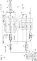
図1は、第1実施例に係る能動型効果音発生装置10を搭載した車両12の概略構成を示すブロック図である。
[First embodiment]
[Configuration of First Embodiment]
FIG. 1 is a block diagram showing a schematic configuration of a
車両12は、燃料電池自動車やハイブリッド自動車等を含む電気自動車(マニュアル運転自動車の他、自動運転自動車でもよい。)であり、車輪(駆動輪)102の駆動源としてモータ100を備える。モータ100は、コンピュータであるモータECU(Electronic Control Unit)104により制御される。
The
モータECU104には、アクセルペダル106の開度を検出するアクセル開度センサ14からアクセル開度θapが供給されている。
The accelerator opening θap is supplied to the
モータECU104は、アクセル開度θapに従いモータ100を駆動し、駆動されたモータ100は、車軸101を介して車輪102を回転させる。モータ100と車軸101との間にトランスミッションを介してもよい。
The
モータ100の回転数あるいは車軸101の回転数に基づき車速センサ16により車速v[km/h]が検出される。
A vehicle speed v [km / h] is detected by the
能動型効果音発生装置10は、音響制御ECUにより構成され、車速センサ16から供給される車速v、及びアクセル開度センサ14から供給されるアクセル開度θapに応じた音響信号Sadを生成し、図示しないD/A変換器を介してスピーカ20に供給する。
The active
スピーカ20は、能動型効果音発生装置10により生成された音響信号Sadに対応する効果音を車室内に出力する。
The
能動型効果音発生装置10は、車速vに基づいて次数音響周波数fc、fd、feを有する次数音響信号Sc、Sd、Seを生成する波形データテーブル(次数音響信号生成器ともいう。)22と、次数音響信号Sc、Sd、Seの振幅(ゲイン)をそれぞれ調整(通常、増幅)して次数音響信号Sc´、Sd´、Se´を生成するゲインCテーブル24cとゲインDテーブル24dとゲインEテーブル24eからなる振幅データテーブル(次数毎の車速ゲインテーブルともいう。)24と、次数音響信号Sc´、Sd´、Se´を合成(加算)して音響信号Sbを生成する加算器26と、を備える。
The active
ここで、ゲインCテーブル24cとゲインDテーブル24dとゲインEテーブル24eは、それぞれ、車速vに応じて次数音響周波数fc、fd、feの振幅を個々に定義する(変化させる)テーブルデータである。 Here, the gain C table 24c, the gain D table 24d, and the gain E table 24e are table data that individually define (change) the amplitudes of the order acoustic frequencies fc, fd, and fe according to the vehicle speed v.
なお、次数音響周波数fc、fd、feの数は、3個に限らず、4個、5個、…10個以上等、2個以上の複数個に選択される。 The number of order acoustic frequencies fc, fd, and fe is not limited to three, but may be selected to be two or more, such as four, five,..., Ten or more.
能動型効果音発生装置10は、また、車速vを微分して車両加速度Δaを生成する車両加速度生成器28と、車速ゲインテーブル30、アクセルゲインテーブル32、及び加速度ゲインテーブル34からなる振幅データテーブル(ゲイン生成器ともいう。)36と、乗算器38と、加算器40と、を備える。
The active
図2Aは、車速ゲインテーブル30、図2Bは、アクセルゲインテーブル32、図2Cは、加速度ゲインテーブル34の例を示すマップ(特性)である。 FIG. 2A is a map (characteristic) showing an example of the vehicle speed gain table 30, FIG. 2B is an accelerator gain table 32, and FIG.
車速ゲインテーブル30は、供給される車速vに対し、低中速域まで出力される車速ゲインGvが一定で、低中速域から高速域まで出力される車速ゲインGvが線形に増加する特性になっている。 The vehicle speed gain table 30 has a characteristic that the vehicle speed gain Gv output from the low to medium speed region is constant with respect to the supplied vehicle speed v, and the vehicle speed gain Gv output from the low to medium speed region increases linearly. Has become.
アクセルゲインテーブル32は、供給されるアクセル開度θapに対し、低中速域まで出力されるアクセルゲイン(アクセル開度ゲインともいう。)Gapが一定で、低中速域から中高速域まで出力されるアクセルゲインGapが線形に増加し、高速域では出力されるアクセルゲインGapが一定の特性になっている。 The accelerator gain table 32 has a constant accelerator gain (also referred to as accelerator opening gain) Gap to be output up to a low-to-medium-speed region with respect to the supplied accelerator opening θap, and outputs from a low-to-medium-speed region to a middle-to-high-speed region. Accelerator gain Gap linearly increases, and the output accelerator gain Gap has a constant characteristic in a high-speed range.
加速度ゲインテーブル34は、供給される車両加速度Δaに対し、低中速域まで出力される加速度ゲインGΔaが一定で、低中速域から高速域まで出力される加速度ゲインGΔaが対数的に増加する特性になっている。 The acceleration gain table 34 shows that the acceleration gain GΔa output from the low to medium speed range is constant with respect to the supplied vehicle acceleration Δa, and the acceleration gain GΔa output from the low to medium speed range to the high speed range increases logarithmically. It is a characteristic.
車速ゲインGvとアクセルゲインGapが乗算器38で乗算され、乗算結果(積:Gv×Gap)に対し、加算器40で加速度ゲインGΔaが加算され、加算結果(和:Gv×Gap+GΔa)が調整ゲインGs(Gs=Gv×Gap+GΔa)として出力される。
The vehicle speed gain Gv and the accelerator gain Gap are multiplied by the
さらに、能動型効果音発生装置10は、ゲインの調整が可能なゲインアンプ42を備えている。
Further, the active
ゲインアンプ42は、加算器26から供給される音響信号Sbのゲインを、加算器40から供給される調整ゲインGs倍して、音響信号Sadを生成しスピーカ20に供給する可変ゲインアンプとして機能する。
The
[波形データテーブル22の構成と作用]
波形データテーブル22の構成と作用について説明する。
[Configuration and Function of Waveform Data Table 22]
The configuration and operation of the waveform data table 22 will be described.
波形データテーブル22は、車速vに基づいて基本車速対応周波数(基本周波数、車速対応周波数ともいう。)fnを生成する基本周波数生成テーブル(車速対応周波数生成テーブル又は基本車速対応周波数生成器もしくは車速対応周波数生成器ともいう。)50と、基本周波数fnから、それぞれ、次数音響周波数fc、fd、feを有する次数音響信号Sc、Sd、Seを生成する次数音響信号生成テーブル(次数音響信号生成器ともいう。)52c、52d、52eからなる次数音響信号生成テーブル52と、を備える。 The waveform data table 22 includes a basic frequency generation table (a vehicle speed corresponding frequency generation table or a basic vehicle speed corresponding frequency generator or a vehicle speed corresponding frequency generator) for generating a basic vehicle speed corresponding frequency (also referred to as a basic frequency or a vehicle speed corresponding frequency) fn based on the vehicle speed v. An order acoustic signal generation table (also referred to as an order acoustic signal generator) that generates order acoustic signals Sc, Sd, and Se having the order acoustic frequencies fc, fd, and fe from the fundamental frequency fn and 50, respectively. ), And an order acoustic signal generation table 52 composed of 52c, 52d, and 52e.
図3は、基本周波数生成テーブル50の一例のマップ(特性)を示している。基本周波数生成テーブル50の特性図と考えてもよい。 FIG. 3 shows an example of a map (characteristic) of the fundamental frequency generation table 50. It may be considered as a characteristic diagram of the fundamental frequency generation table 50.
横軸が車速vで、車速v=0から車速v=v1まで、車速v=v1から車速v=v2まで、車速v=v2から車速v=v3まで、車速v=v3から車速v=v3以上と4分割されている。この第1実施例では、後述する周波数変化率調整係数kを車速vに対して定数としているので、v1=v2−v1=v3−v2…と等分割になっている。 The horizontal axis is the vehicle speed v, from v = 0 to v = v1, from v = v1 to v = v2, from v = v2 to v = v3, from v = v3 to v = v3 or more. Is divided into four. In the first embodiment, since a frequency change rate adjustment coefficient k, which will be described later, is a constant with respect to the vehicle speed v, it is equally divided as v1 = v2-v1 = v3-v2.
縦軸が基本周波数fnで、下限周波数Fminから上限周波数Fmaxまでが定義されている。この場合、下限周波数Fminは、スピーカ20から出力可能な音の最低周波数以上の低周波数に設定され、上限周波数Fmaxは、乗員がスピーカ20から音が出力されていると気づき難い上限周波数以下の高周波数に設定されている。下限周波数Fmin及び上限周波数Fmaxは、車両構造、シート位置等、車室内の構造にも影響されるので、各値は、車種毎にチューニングされる。
The vertical axis is the fundamental frequency fn, and defines the lower limit frequency Fmin to the upper limit frequency Fmax. In this case, the lower limit frequency Fmin is set to a low frequency equal to or higher than the lowest frequency of the sound that can be output from the
ここで、基本周波数fnは、例えば、車速v=v1の下限周波数Fminから車速v2の上限周波数Fmaxまで指数関数的に増加する。 Here, the fundamental frequency fn increases exponentially from, for example, the lower limit frequency Fmin of the vehicle speed v = v1 to the upper limit frequency Fmax of the vehicle speed v2.
車速v=0〜v1、車速v=v2〜v3、車速v=v3以上で、車速v=v1〜v2までと同じ指数関数的増加を繰り返す、いわゆるシェパードの無限音階に近似した設定とされている。 The vehicle speed v = 0 to v1, the vehicle speed v = v2 to v3, and the vehicle speed v = v3 or higher, and the same exponential increase as the vehicle speed v = v1 to v2 is repeated. .
具体的には、指数関数の底(後述する定数倍と同じ)をa(a>1)とし、「^」を累乗として、基本周波数fnを、次の(1)式により算出するようにしている。
fn=Fmin×a^{(v−V)/k},If fn≧Fmax
Then V→V+1(0、v1、v2、又はv3、…) …(1)
なお、(1)式では、毎回、下限周波数Fminをベースに基本周波数fnを計算しているので、上限周波数Fmaxから下限周波数Fminに戻す必要はない。
Specifically, the base of the exponential function (same as a constant multiple to be described later) is a (a> 1), "^" is a power, and the fundamental frequency fn is calculated by the following equation (1). I have.
fn = Fmin × a ^ {(v−V) / k}, If fn ≧ Fmax
Then V → V + 1 (0, v1, v2, or v3,...) (1)
In equation (1), since the fundamental frequency fn is calculated each time based on the lower limit frequency Fmin, it is not necessary to return the upper limit frequency Fmax to the lower limit frequency Fmin.
但し、fn:基本周波数(基本車速対応周波数)、Fmin:下限周波数、a:定数倍、v:車速、V:V=0、v1、v2、v3、…であって、基本周波数fnが上限周波数Fmaxとなる車速、及びk:周波数変化率調整係数であって、kはk>0で、この第1実施例では、kが定数である。このように、基本周波数fnは、変数としての車速vの指数関数であり、残りFmin、a、V、Fmax、及びkはパラメータである。 Where fn: basic frequency (basic vehicle speed corresponding frequency), Fmin: lower limit frequency, a: constant multiple, v: vehicle speed, V: V = 0, v1, v2, v3,... Fmax, the vehicle speed, and k: frequency change rate adjustment coefficient, where k is greater than 0, and k is a constant in the first embodiment. Thus, the fundamental frequency fn is an exponential function of the vehicle speed v as a variable, and the remaining Fmin, a, V, Fmax, and k are parameters.
図4は、基本周波数生成テーブル50と、次数音響信号生成テーブル52の構成及び作用の説明、すなわち波形データテーブル22の構成及び作用の説明に供される特性図である。 FIG. 4 is a characteristic diagram used to describe the configuration and operation of the fundamental frequency generation table 50 and the order acoustic signal generation table 52, that is, the configuration and operation of the waveform data table 22.
図4から分かるように、周波数変化率調整係数kは、物理的な意味合いとして、効果音の周波数構成が繰り返される周期(車速間隔)である。周波数変化率調整係数kの値は、車速vに基づき設定される。 As can be seen from FIG. 4, the frequency change rate adjustment coefficient k is, as a physical meaning, a cycle (vehicle speed interval) in which the frequency configuration of the sound effect is repeated. The value of the frequency change rate adjustment coefficient k is set based on the vehicle speed v.
図4において、例えば、時点t1、t2、t3において、次数c(Ord c)、次数d(Ord d)、次数e(Ord e)の周波数fの大小関係が入れ替わっているが、周波数成分としてはFmin、Fmin×a、Fmin×a^2と同じ構成になっている。 In FIG. 4, for example, at times t1, t2, and t3, the magnitude relation of the frequency f of the order c (Ord c), the order d (Ord d), and the order e (Ord e) is switched. It has the same configuration as Fmin, Fmin × a, and Fmin × a ^ 2.
ここで、時点t1、t2、t3の車速間隔は、周波数変化率調整係数kで定義される。周波数変化率調整係数kが大きいほど、同じ周波数構成に戻るまでの車速間隔が大きくなり、周波数変化率が小さくなる。 Here, the vehicle speed intervals at time points t1, t2, and t3 are defined by a frequency change rate adjustment coefficient k. As the frequency change rate adjustment coefficient k is larger, the vehicle speed interval before returning to the same frequency configuration becomes larger, and the frequency change rate becomes smaller.
例えば、k=20の場合、20[km/h]毎に効果音の周波数構成が同じになる。この場合、20[km/h]毎に、下限周波数Fminから上限周波数Fmaxまで変化する周波数構成が繰り返されるような設定になる{上記(1)式参照}。 For example, when k = 20, the frequency configuration of the sound effect becomes the same every 20 [km / h]. In this case, the setting is such that the frequency configuration changing from the lower limit frequency Fmin to the upper limit frequency Fmax is repeated every 20 [km / h] {see the above equation (1)}.
また、1つの次数に対して、上限周波数Fmaxになる車速間隔(v1、v2−v1)は、OrdN×kとなる。OrdNは、次数周波数の数であり、図4例では、Ord c、Ord d、Ord eと、OrdN=3である。 The vehicle speed interval (v1, v2−v1) at which the upper limit frequency Fmax is obtained for one order is OrdN × k. OrdN is the number of order frequencies, and in the example of FIG. 4, Ordc, Ordd, Orde, and OrdN = 3.
図4中、車速vがv=v1のとき、次数音響信号生成テーブル52cでは、次数c(Ord cという。)の次数音響周波数fcを有する次数音響信号Sc=Sc1を生成する際に、基本周波数fn(図3も参照)を参照して、次数音響周波数fc=fc1=Fminを生成した後、該次数音響周波数fc1を有する一定振幅の次数音響信号Sc1を生成する。 In FIG. 4, when the vehicle speed v is v = v1, the order acoustic signal Sc = Sc1 having the order acoustic frequency fc of the order c (referred to as Ord c) is generated in the order acoustic signal generation table 52c. With reference to fn (see also FIG. 3), after generating the order acoustic frequency fc = fc1 = Fmin, a constant amplitude order acoustic signal Sc1 having the order acoustic frequency fc1 is generated.
また、車速vがv=v1のとき、次数音響信号生成テーブル52dでは、次数d(Ord dという。)の次数音響周波数fd1を有する次数音響信号Sd=Sd1を生成する際に、次数音響周波数fc=fc1をa倍して生成する(fd1=a×fc1=a×Fmin)。そして、該次数音響周波数fd1を有する一定振幅の次数音響信号Sd1を生成する。 When the vehicle speed v is v = v1, the order acoustic frequency fc is generated in the order acoustic signal generation table 52d when the order acoustic signal Sd = Sd1 having the order acoustic frequency fd1 of the order d (referred to as Ord d) is generated. = Fc1 is multiplied by a (fd1 = a × fc1 = a × Fmin). Then, an order acoustic signal Sd1 having a constant amplitude having the order acoustic frequency fd1 is generated.
さらに、車速vがv=v1のとき、次数音響信号生成テーブル52eでは、次数e(Ord eという。)の次数音響周波数fe1を有する次数音響信号Se=Se1を生成する際に、次数音響周波数fc=fc1をa^2倍して生成する(fe1=a×a×fc1=fc1×a^2=Fmin×a^2)。そして、該次数音響周波数fd1を有する一定振幅の次数音響信号Sd1を生成する。 Further, when the vehicle speed v is v = v1, in the order acoustic signal generation table 52e, when the order acoustic signal Se = Se1 having the order acoustic frequency fe1 of the order e (referred to as Order e) is generated, the order acoustic frequency fc is generated. = Fc1 multiplied by a ^ 2 (fe1 = a × a × fc1 = fc1 × a ^ 2 = Fmin × a ^ 2). Then, an order acoustic signal Sd1 having a constant amplitude having the order acoustic frequency fd1 is generated.
同様に、図4中、車速vがv=vnのとき、次数音響信号生成テーブル52cでは、次数c(Ord c)の次数音響周波数fcを有する次数音響信号Sc=Scnを生成する際に、基本周波数fn(図3も参照)を参照して、次数音響周波数fc=fcnを生成した後、該次数音響周波数fcnを有する一定振幅の次数音響信号Scnを生成する。 Similarly, in FIG. 4, when the vehicle speed v is v = vn, in the order acoustic signal generation table 52c, when generating the order acoustic signal Sc = Scn having the order acoustic frequency fc of the order c (Ord c), After generating the order acoustic frequency fc = fcn with reference to the frequency fn (see also FIG. 3), the order acoustic signal Scn having the order acoustic frequency fcn and having a constant amplitude is generated.
また、車速vがv=vnのとき、次数音響信号生成テーブル52dでは、次数d(Ord d)の次数音響周波数fdnを有する次数音響信号Sd=Sdnを生成する際に、次数音響周波数fc=fcnをa倍して生成する(fdn=a×fcn)。そして、該次数音響周波数fdnを有する一定振幅の次数音響信号Sdnを生成する。 Further, when the vehicle speed v is v = vn, the order acoustic frequency fc = fcn is used in the order acoustic signal generation table 52d to generate the order acoustic signal Sd = Sdn having the order acoustic frequency fdn of the order d (Ord d). Is multiplied by a (fdn = a × fcn). Then, an order acoustic signal Sdn having a constant amplitude having the order acoustic frequency fdn is generated.
さらに、車速vがv=vnのとき、次数音響信号生成テーブル52eでは、次数e(Ord e)の次数音響周波数fenを有する次数音響信号Se=Senを生成する際に、次数音響周波数fc=fcnをa^2倍して生成する(fen=a×a×fcn=fcn×a^2)。そして、該次数音響周波数fenを有する一定振幅の次数音響信号Sdnを生成する。 Further, when the vehicle speed v is v = vn, in the order acoustic signal generation table 52e, when the order acoustic signal Se = Sen having the order acoustic frequency fen of the order e (Orde) is generated, the order acoustic frequency fc = fcn. Is multiplied by a ^ 2 (fen = a × a × fcn = fcn × a ^ 2). Then, it generates an order acoustic signal Sdn of a constant amplitude having the order acoustic frequency fen.
少し詳しくなるが、念のために説明すると、同様に、図4中、車速vがv=vmのとき、次数音響信号生成テーブル52cでは、次数c(Ord c)の次数音響周波数fcを有する次数音響信号Sc=Scmを生成する際に、基本周波数fn(図3も参照)を参照して、次数音響周波数fc=fcmを生成した後、該次数音響周波数fcmを有する一定振幅の次数音響信号Scmを生成する。 Although described in detail, just in case, in FIG. 4, similarly, when the vehicle speed v is v = vm, in the order acoustic signal generation table 52c, the order having the order acoustic frequency fc of the order c (Ord c) is obtained. When generating the acoustic signal Sc = Scm, after generating the order acoustic frequency fc = fcm with reference to the fundamental frequency fn (see also FIG. 3), the order acoustic signal Scm having a constant amplitude having the order acoustic frequency fcm. Generate
また、車速vがv=vmのとき、次数音響信号生成テーブル52dでは、次数d(Ord d)の次数音響周波数fdmを有する次数音響信号Sd=Sdmを生成する際に、次数音響周波数fc=fcmをa倍して生成する(fdm=a×fcm)。そして、該次数音響周波数fdmを有する一定振幅の次数音響信号Sdmを生成する。 Further, when the vehicle speed v is v = vm, the order acoustic frequency fc = fcm in the order acoustic signal generation table 52d when the order acoustic signal Sd = Sdm having the order acoustic frequency fdm of the order d (Ord d) is generated. Is multiplied by a (fdm = a × fcm). Then, an order acoustic signal Sdm having a constant amplitude having the order acoustic frequency fdm is generated.
さらに、車速vがv=vmのとき、次数音響信号生成テーブル52eでは、次数e(Ord e)の次数音響周波数femを有する次数音響信号Se=Semを生成する際に、fem=fcm×a^2とするが、このfem=fcm×a^2の値は、fem≧Fmaxとなっている。このとき、femは、fem=fem/(a^OrdN)となるので、fem=fem/a^3になり、fem=fcm×a^2/a^3=fcm/aになる。結果として、この第1実施例では、OrdN=3であるので、次数音響周波数femを生成する際、次数音響周波数fcmを1/a倍して生成すればよい。そして、該次数音響周波数femを有する一定振幅の次数音響信号Sdmを生成する。 Further, when the vehicle speed v is v = vm, in the order acoustic signal generation table 52e, when generating the order acoustic signal Se = Sem having the order acoustic frequency fem of the order e (Orde), fem = fcm × a ^. 2, the value of fem = fcm × a ^ 2 satisfies fem ≧ Fmax. At this time, fem becomes fem = fem / (a ^ OrdN), so that fem = fem / a ^ 3, and fem = fcm × a ^ 2 / a ^ 3 = fcm / a. As a result, in the first embodiment, since OrdN = 3, the order acoustic frequency fcm may be generated by multiplying the order acoustic frequency fcm by 1 / a. Then, an order acoustic signal Sdm having a constant amplitude having the order acoustic frequency fem is generated.
このように次数音響信号(fc1、fd1、fe1)、(fcn、fdn、fen)、(fcm、fdm、fem)は、次の(2)式に示すように、各次数成分の周波数比が常に定数倍aになっている。なお、特にa=2の場合、各次数成分の次数音響周波数fc1、fd1、fe1、fcn、fdn、fen、fcm、fdm、femは、調和(2倍、4倍、…)になっている。 As described above, the order acoustic signals (fc1, fd1, fe1), (fcn, fdn, fen), and (fcm, fdm, fem) always have a frequency ratio of each order component as shown in the following equation (2). It is a constant multiple a. In particular, when a = 2, the order acoustic frequencies fc1, fd1, fe1, fcn, fdn, fen, fcm, fdm, and fem of the respective order components are in harmony (double, quadruple,...).
fc1:fd1:fe1=fcn:fdn:fen=fem:fcm:fdm=1:a:a^(OrdN−1) …(2)
第1実施例の場合、OrdN=3であるので、1:2:4になる。
fc1: fd1: fe1 = fcn: fdn: fen = fem: fcm: fdm = 1: a: a ^ (OrdN-1) (2)
In the case of the first embodiment, since OrdN = 3, the ratio is 1: 2: 4.
このようにして、波形データテーブル22において、車速vに基づき基本周波数生成テーブル50で生成された基本周波数fnから次数音響信号生成テーブル52c、52d、52eにより、それぞれが車速対応周波数である次数音響周波数fc、fd、feを有する次数音響信号Sc、Sd、Seが生成される。 In this manner, in the waveform data table 22, the order acoustic frequencies each corresponding to the vehicle speed are obtained from the fundamental frequency fn generated in the fundamental frequency generation table 50 based on the vehicle speed v by the order acoustic signal generation tables 52c, 52d, and 52e. The order acoustic signals Sc, Sd, Se having fc, fd, fe are generated.
ここで、具体的な数値例での計算例を説明する。
(1)式において、a=2、Fmin=60[Hz]、OrdN=3、Fmax=Fmin×a^OrdN=60×2^3=480[Hz]、k=20[km/h]とする。
Here, a calculation example using a specific numerical example will be described.
In the equation (1), a = 2, Fmin = 60 [Hz], OrdN = 3, Fmax = Fmin × a ^ OrdN = 60 × 2 ^ 3 = 480 [Hz], and k = 20 [km / h]. .
1.車速v=k=20[km/h]の場合、基本周波数fnは、fn=Fmin×2^{(20−0)/20}=120[Hz]で、Ord eの次数音響周波数fe=fn×2^2=480[Hz]=Fmaxになる。
その直後にfe=fe/(a^OrdN)=60[Hz]=Fminと、次数音響周波数feを下限周波数Fmin方向に戻す。
このとき、音の周波数構成は、0[km/h]時と同じく60[Hz](Ord e)、120[Hz](Ord c)、240[Hz](Ord d)となる。このように、効果音は、周波数変化率調整係数kの車速間隔で繰り返される。
1. When the vehicle speed v = k = 20 [km / h], the fundamental frequency fn is fn = Fmin × 2 {(20-0) / 20} = 120 [Hz], and the order acoustic frequency of Orde fe = fn. × 2 ^ 2 = 480 [Hz] = Fmax.
Immediately thereafter, the order acoustic frequency fe is returned in the direction of the lower limit frequency Fmin, where fe = fe / (a ^ OrdN) = 60 [Hz] = Fmin.
At this time, the frequency configuration of the sound is 60 [Hz] (Orde), 120 [Hz] (Ordc), and 240 [Hz] (Ord d) as in the case of 0 [km / h]. Thus, the sound effect is repeated at the vehicle speed interval of the frequency change rate adjustment coefficient k.
2.車速v=v1=k×OrdNのとき、(1)式より、V=0[km/h]、fn=Fmin×2^{(60−0)/20}=480[Hz]=Fmaxになる。
このように、v=k×OrdNの間隔で基本周波数fnが下限周波数Fminから上限周波数Fmaxになる。ここで、fn=fcであるが、fd、feも同様な車速間隔で上限周波数Fmaxになる。
2. When the vehicle speed v = v1 = k × OrdN, from equation (1), V = 0 [km / h] and fn = Fmin × 2 {(60-0) / 20} = 480 [Hz] = Fmax. .
Thus, the fundamental frequency fn changes from the lower limit frequency Fmin to the upper limit frequency Fmax at intervals of v = k × OrdN. Here, fn = fc, but fd and fe also have the upper limit frequency Fmax at similar vehicle speed intervals.
3.その直後に、V=v1=60[km/h]になり、fn=Fmin×2^{(60−60)/20}=Fminになって、基本周波数fnが下限周波数Fminに戻る。 3. Immediately after that, V = v1 = 60 [km / h], fn = Fmin × 2 {(60−60) / 20} = Fmin, and the fundamental frequency fn returns to the lower limit frequency Fmin.
4.v2=120[km/h]のとき、V=60[km/h]、fn=Fmin×2^{(120−60)/20}=480[Hz]=Fmaxになる。このように、v=k×OrdNの間隔(v2−v1)で基本周波数fnが、下限周波数Fminから上限周波数Fmaxになる。 4. When v2 = 120 [km / h], V = 60 [km / h] and fn = Fmin × 2 {(120−60) / 20} = 480 [Hz] = Fmax. As described above, the fundamental frequency fn changes from the lower limit frequency Fmin to the upper limit frequency Fmax at an interval (v2−v1) of v = k × OrdN.
[第1実施例の全体動作]
音響制御ECUにより構成される能動型効果音発生装置10は、サンプリングクロックに基づき、msオーダーのきわめて短い時間に、車速vに基づく無限音階に係る音響信号Sadを生成(制御)する。制御の主体は、音響制御ECU(のCPU)である。
[Overall Operation of First Embodiment]
The active
停車中又は一定速度で走行中の車両12のアクセルペダル106が運転者により踏み込まれると、モータECU104を通じてモータ100が回転駆動され、この回転駆動により車軸101を通じて車輪102が回転されることで、車両12が加速される。
When the driver depresses the
加速中に、車速センサ16により車速vが検出される。検出された車速vにより波形データテーブル22が参照されて、車速vが、例えば、v=0〜v1の間で、基本周波数生成テーブル50により基本周波数fnが生成され(図3)、生成した基本車速対応周波数fnに基づき、次数音響信号生成テーブル52c、52d、52eが参照されて次数音響信号Sc、Sd、Seが生成される{(2)式}。
The vehicle speed v is detected by the
生成された次数音響信号Sc、Sd、Seの振幅が、振幅データテーブル24が参照されて調整され(ゲイン倍され)次数音響信号Sc´、Sd´、Se´が生成され、加算器26で合成されて音響信号Sbが生成される。生成された音響信号Sbは、ゲインアンプ42の入力端子に供給される。
The amplitudes of the generated order acoustic signals Sc, Sd, Se are adjusted (gain multiplied) with reference to the amplitude data table 24 to generate the order acoustic signals Sc ′, Sd ′, Se ′, and synthesized by the
以下、同様にして、(1)式により計算される図4に示した波形データテーブル22(次数音響信号生成テーブル52)の特性に沿い、車速vの増加に対して、下限周波数Fminと上限周波数Fmaxで繰り返す複数の次数音響信号Sc、Sd、Seからなる音響信号Sbがゲインアンプ42の入力端子に供給される。
In the same manner, the lower limit frequency Fmin and the upper limit frequency are calculated in accordance with the characteristics of the waveform data table 22 (order acoustic signal generation table 52) shown in FIG. A sound signal Sb composed of a plurality of order sound signals Sc, Sd, and Se repeated at Fmax is supplied to an input terminal of the
波形データテーブル22と振幅データテーブル24とにより音響信号Sbが生成される動作と並列的に、車速vと、車速vに基づき車両加速度生成器28により生成された加速度Δaと、アクセル開度θapと、から、それぞれ車速ゲインテーブル30(図2A)、加速度ゲインテーブル34(図2C)、及びアクセルゲインテーブル32(図2B)を参照して、さらに乗算器38及び加算器40により前記音響信号Sbを増強するための調整ゲインGs(Gs=Gv×Gap+GΔa)が生成され、ゲインアンプ42のゲイン調整端子に供給される。
In parallel with the operation in which the sound signal Sb is generated by the waveform data table 22 and the amplitude data table 24, the vehicle speed v, the acceleration Δa generated by the
調整ゲインGsにより音響信号Sbのゲイン(振幅)が調整(車両12の加速過程では増強)され、調整後の音響信号Sadがスピーカ20に供給される。
The gain (amplitude) of the audio signal Sb is adjusted (increased in the process of accelerating the vehicle 12) by the adjustment gain Gs, and the adjusted audio signal Sad is supplied to the
これによりスピーカ20から車室内に、例として、図4に示したように、車速vの増加に対して、下限周波数Fminと上限周波数Fmaxで繰り返す3つの次数音響周波数fc、fd、feから聞こえる3つの効果音、いわゆる無限音階での3つの効果音が合成された効果音を発生することができる。結果として、車速vの増加に応じて、自動車走行音としてリアリティの高い効果音を発生することができる。
As a result, as shown in FIG. 4, for example, as shown in FIG. 4, three order acoustic frequencies fc, fd, and fe repeated from the
[第1実施例の効果]
上記した第1実施例の効果を、比較例と対比して説明する。
[Effect of First Embodiment]
The effect of the first embodiment will be described in comparison with a comparative example.
図5は、比較例の車速v対周波数fの波形データテーブル(比較例の波形データテーブルという。)60を示している。 FIG. 5 shows a waveform data table (referred to as a waveform data table of the comparative example) 60 of the vehicle speed v and the frequency f of the comparative example.
一般に、スピーカ20と車室内指向性に基づき、効果音のリアリティを損なわずに再生可能な周波数範囲は、下限周波数Fminと上限周波数Fmaxとの間である。
Generally, the frequency range that can be reproduced without impairing the reality of the sound effect is between the lower limit frequency Fmin and the upper limit frequency Fmax based on the
図5の比較例において、周波数fは、低次数の特性Ord c、中次数の特性Ord d、及び高次数の特性Ord eを参照して、それぞれf=K×v(常数Kと車速v)により発生可能である。 In the comparative example of FIG. 5, the frequency f is f = K × v (constant K and vehicle speed v) with reference to the low-order characteristic Ord c, the middle-order characteristic Ord d, and the high-order characteristic Orde, respectively. This can be caused by
比較例において、前記周波数範囲内を利用可能範囲の周波数とすると、第1に低次数の特性Ord cは、広い車速範囲で効果音を発生できるが、車速変化量に対する周波数変化量が小さい。第2に、高次数の特性Ord eは、車速変化量に対する周波数変化量は大きいが、効果音を発生できる車速範囲が狭い。結果として、効果音のリアリティを損なわない車速vの範囲は、車速vrまでの狭い範囲になる。 In the comparative example, assuming that a frequency within the usable frequency range is set within the frequency range, firstly, the low-order characteristic Ordc can generate a sound effect over a wide vehicle speed range, but the frequency change amount with respect to the vehicle speed change amount is small. Second, the high-order characteristic Orde has a large frequency change with respect to the vehicle speed change, but has a narrow vehicle speed range in which a sound effect can be generated. As a result, the range of the vehicle speed v that does not impair the reality of the sound effect is a narrow range up to the vehicle speed vr.
これに対して、第1実施例では、図4に示したように、無限音階のコンセプトを利用し、一定な周波数範囲Fmin〜Fmax内で、同一車速vで複数の次数音響周波数fc、fd、feの各次数成分の周波数比が常に定数aである効果音を繰り返させることで、比較的低周波領域の音のみを利用しても、車速vと車両加速度Δaに応じた違和感のない加速効果音を発生させることができるようになり、前述した問題点が解決される。 On the other hand, in the first embodiment, as shown in FIG. 4, the concept of the infinite scale is used, and a plurality of order acoustic frequencies fc, fd, at the same vehicle speed v within a fixed frequency range Fmin to Fmax. By repeating the effect sound in which the frequency ratio of each order component of fe is always a constant a, the acceleration effect without a sense of incongruity according to the vehicle speed v and the vehicle acceleration Δa even when using only sounds in a relatively low frequency region. A sound can be generated, and the above-mentioned problem is solved.
すなわち、第1実施例による能動型効果音発生装置10によれば、車速vの増加に応じて発生する効果音が、車速vの高速領域であっても自動車走行音としてのリアリティ(自然感)の高さを維持することができる。
That is, according to the active
[変形例]
上述した第1実施例では、図3に示した基本周波数生成テーブル50を参照して車速vに対する基本周波数(基本車速対応周波数)fnを生成するようにしている。この場合、上記(1)式中の下限周波数Fmin、上限周波数Fmax、及び周波数変化率調整係数kの各パラメータは、それぞれ定数としている。
[Modification]
In the first embodiment described above, the basic frequency (basic vehicle speed corresponding frequency) fn for the vehicle speed v is generated with reference to the basic frequency generation table 50 shown in FIG. In this case, each parameter of the lower limit frequency Fmin, the upper limit frequency Fmax, and the frequency change rate adjustment coefficient k in the above equation (1) is a constant.
後述する第2実施例及び第3実施例では、これらのパラメータ(Fmin、Fmax、k)を変数とすることで、基本周波数fnを車速vの関数として変化させる例を示している。 The second embodiment and the third embodiment described later show examples in which the fundamental frequency fn is changed as a function of the vehicle speed v by using these parameters (Fmin, Fmax, k) as variables.
この変形例は、これらのパラメータを変化させても、基本周波数fnを連続的に算出できるようにした技術である。 This modification is a technique in which the fundamental frequency fn can be continuously calculated even when these parameters are changed.
なお、この変形例(数式による基本車速対応周波数fnの算出)は、パラメータが定数である第1実施例にも利用可能である。 This modified example (calculation of the basic vehicle speed corresponding frequency fn by a mathematical expression) can also be used in the first embodiment in which the parameter is a constant.
図6は、変形例に係る基本車速対応周波数生成器(基本周波数生成テーブル)50Aのアルゴリズムの説明図である。 FIG. 6 is an explanatory diagram of an algorithm of a basic vehicle speed corresponding frequency generator (basic frequency generation table) 50A according to the modification.
基本車速対応周波数fnは、(1)式に示したように算出されるが、図6に示すように、1サンプリング時間前の基本車速対応周波数をfn−1とし、現サンプリング時間での車速変化量Δvが十分に小さい場合には、現在の基本車速対応周波数fnと、1サンプリング時間前の基本車速対応周波数fn−1との間のカーブは直線で近似することができる。 The basic vehicle speed corresponding frequency fn is calculated as shown in equation (1). As shown in FIG. 6, the basic vehicle speed corresponding frequency one sampling time ago is fn-1, and the vehicle speed change at the current sampling time is fn-1. When the amount Δv is sufficiently small, the curve between the current basic vehicle speed corresponding frequency fn and the basic vehicle speed corresponding frequency fn−1 one sampling time before can be approximated by a straight line.
そうすると、周波数変化量Δfnは、(1)式の指数関数を車速vで微分したときの微分値をf´とすると、次の(3)式により算出することができる。
Δfn=f´×Δv
={(loga)/k}×Fmin×a^{(v−V)/k}×Δv …(3)
Then, the frequency variation Δfn can be calculated by the following equation (3), where f ′ is a differential value obtained by differentiating the exponential function of equation (1) with the vehicle speed v.
Δfn = f ′ × Δv
= {(Loga) / k} × Fmin × a ^ {(v−V) / k} × Δv (3)
この周波数変化量Δfnを計算することで、現在の基本車速対応周波数fnは、1サンプリング時間前の基本車速対応周波数fn−1と、1サンプリング時間での周波数変化量Δfnを用いて、次の(4)式により逐次的に算出することができる。
fn=fn−1+Δfn …(4)
By calculating the frequency change amount Δfn, the current basic vehicle speed corresponding frequency fn is calculated by using the basic vehicle speed corresponding frequency fn−1 one sampling time ago and the frequency change amount Δfn at one sampling time as follows: It can be calculated sequentially according to equation 4).
fn = fn-1 + Δfn (4)
よって、この変形例においては、車速v=0〜v1、車速v=v2〜v3、車速v=v3以上で、指数関数の底(後述する定数倍と同じ)をa(a>1)とし、「^」を累乗として、基本車速対応周波数fnは、次の(5)式により算出することができる。 Therefore, in this modified example, the vehicle speed v = 0 to v1, the vehicle speed v = v2 to v3, the vehicle speed v = v3 or more, and the base of the exponential function (same as a constant multiple described later) is a (a> 1). Assuming that “^” is a power, the basic vehicle speed corresponding frequency fn can be calculated by the following equation (5).
fn=fn−1+Δfn、
Δfn=
{(loga)/k}×Fmin×a^{(v−V)/k}×Δv、
If fn≧Fmax
Then V→V+1(0、v1、v2、又はv3、…)、fn→Fmin …(5)
fn = fn-1 + Δfn,
Δfn =
{(Loga) / k} × Fmin × a ^ {(v−V) / k} × Δv,
If fn ≧ Fmax
Then V → V + 1 (0, v1, v2, or v3,...), Fn → Fmin (5)
この変形例では、逐次計算により、加速に伴い、基本車速対応周波数fnが大きくなる一方であるので、fnがFmaxとなったとき、fnをFminに戻す必要があることに留意する。 In this modified example, it should be noted that the basic vehicle speed corresponding frequency fn is being increased by the successive calculation with the acceleration, so that when fn becomes Fmax, it is necessary to return fn to Fmin.
但し、fn:基本車速対応周波数(車速対応周波数)、Fmin:下限周波数、a:定数倍、v:車速、V:V=0、v1、v2、v3、…であって、基本車速対応周波数fnが上限周波数Fmaxとなる車速、及びk:周波数変化率調整係数である。なお、(3)式及び(4)式を利用するに当たり、車速間隔、例えば、v3−v2とv2−v1は、等しくなくともよい。 Here, fn: frequency corresponding to basic vehicle speed (frequency corresponding to vehicle speed), Fmin: lower limit frequency, a: constant multiple, v: vehicle speed, V: V = 0, v1, v2, v3,. Is the vehicle speed at which the upper limit frequency Fmax is reached, and k is a frequency change rate adjustment coefficient. In using the equations (3) and (4), the vehicle speed intervals, for example, v3-v2 and v2-v1 may not be equal.
上述した第1実施例においても、パラメータを変化させることができるが、パラメータの変化により生成される周波数が不連続になる場合があり、この場合には、聴音として違和感がある。これに対して、変形例の逐次計算の利点としては、連続的に周波数を算出しているので、パラメータ変化時の聴音としての違和感を解消することができる。 In the first embodiment described above, the parameter can be changed, but the frequency generated by the change in the parameter may be discontinuous. In this case, the auditory sound is uncomfortable. On the other hand, as an advantage of the sequential calculation of the modified example, since the frequency is calculated continuously, it is possible to eliminate a sense of incongruity as a hearing sound when a parameter is changed.
[第2実施例]
上記変形例を適用した第2実施例では、第1実施例に比較して、車速vが高くなると、より加速感を味わえるように、上限周波数Fmax又は下限周波数Fminが大きくなるように、基本周波数fnを加工している。
[Second embodiment]
In the second embodiment to which the above-described modification is applied, as compared with the first embodiment, when the vehicle speed v is higher, the fundamental frequency is increased so that the upper limit frequency Fmax or the lower limit frequency Fmin is increased so that the driver can feel more acceleration. fn is being processed.
これを実現するために、第2実施例に係る能動型効果音発生装置10A(図1)では、第1実施例に係る能動型効果音発生装置10に対して、波形データテーブル22を波形データテーブル22Aに変更している。
In order to realize this, in the active
図7Aの車速vに対する周波数変化の特性qから、図7Bの第2実施例の波形データテーブル22Aでは、車速vの増加に対して周波数fの上限周波数Fmax´(又は下限周波数Fmin´)が、車速vがv=0では最小となり、車速vの増加に応じてS字カーブ的に増加し、高車速Vmaxで、最大値となるように設定している。 7A, the upper limit frequency Fmax ′ (or the lower limit frequency Fmin ′) of the frequency f in the waveform data table 22A of the second embodiment of FIG. The vehicle speed v is set to be minimum when v = 0, to increase like an S-curve as the vehicle speed v increases, and to reach a maximum value at a high vehicle speed Vmax.
なお、この第2実施例では、車速vに応じてパラメータである下限周波数Fmin´又は上限周波数Fmax´を変化させているので、基本周波数fnは、変形例の上記(5)式により連続的に算出することができる。 In the second embodiment, since the lower limit frequency Fmin 'or the upper limit frequency Fmax', which is a parameter, is changed according to the vehicle speed v, the fundamental frequency fn is continuously calculated by the above equation (5) of the modification. Can be calculated.
このように第2実施例に係る能動型効果音発生装置10Aでは、車速vが高くなると、より加速感が味わえるように、車速vの低い側に比較して車速vの高い側で周波数範囲が広がるように設定可能になっている。
As described above, in the active sound
すなわち、車速vに応じて、周波数変化率調整係数kや上限周波数Fmax等のパラメータを切り替えても逐次更新により効果音の周波数を連続的に変化させることができる。 That is, even if parameters such as the frequency change rate adjustment coefficient k and the upper limit frequency Fmax are switched according to the vehicle speed v, the frequency of the sound effect can be continuously changed by successive updating.
この第2実施例によれば、無限音階のコンセプトを利用し、下限周波数Fmin´又は上限周波数Fmax´を車速vに応じて変化させた特性の中で、効果音を繰り返し発生させることで、比較的低周波領域の効果音のみを利用しても、車速vと車速加速度Δaに応じた違和感のない加速効果音を発生させることができる。 According to the second embodiment, the sound effect is repeatedly generated in the characteristic in which the lower limit frequency Fmin ′ or the upper limit frequency Fmax ′ is changed according to the vehicle speed v by using the concept of the infinite scale. Even if only the sound effect in the extremely low frequency region is used, it is possible to generate an acceleration effect sound without a sense of incongruity according to the vehicle speed v and the vehicle speed acceleration Δa.
実際上、Fmax=Fmin×a^OrdN(a^OrdNは、決定されたパラメータ)という関係があるので、例えば、一方の上限周波数Fmaxを上限周波数Fmax´に変化させると、下限周波数Fmin´は、この関係に基づいて変化する。より具体的に説明すると、上限周波数Fmax又は下限周波数Fminの一方を、例えば、図7Aの特性qのように車速Vの増加に沿って非線形(線形でもよい。)で増加するように定義すると、図7Bに示すように、上限周波数Fmax´又は下限周波数Fmin´の他方も上記関係に基づいて車速Vの増加に応じて非線形で増加することになる。 Actually, there is a relationship of Fmax = Fmin × a ^ OrdN (a ^ OrdN is a determined parameter). For example, when one upper limit frequency Fmax is changed to the upper limit frequency Fmax ′, the lower limit frequency Fmin ′ becomes It changes based on this relationship. More specifically, if one of the upper limit frequency Fmax and the lower limit frequency Fmin is defined so as to increase non-linearly (or linearly) as the vehicle speed V increases, for example, as shown by the characteristic q in FIG. 7A, As shown in FIG. 7B, the other of the upper limit frequency Fmax ′ and the lower limit frequency Fmin ′ increases non-linearly in accordance with the increase of the vehicle speed V based on the above relationship.
結果として、車速vの増加に応じて発生する効果音が、高速領域であっても自動車走行音としてのリアリティ(自然感)の高さを維持することができる。 As a result, the effect sound generated in accordance with the increase in the vehicle speed v can maintain the high level of the reality (natural feeling) as the vehicle running sound even in a high-speed region.
[第3実施例]
この第3実施例では、第1実施例に比較して、車速vが高くなると、より加速感を味わえるように、車速vの増加に対する周波数変化量(Δf/Δv)が大きくなるように、車速対応周波数fnを加工している。
[Third embodiment]
In the third embodiment, as compared with the first embodiment, when the vehicle speed v is increased, the vehicle speed is increased so that the frequency change amount (Δf / Δv) with respect to the increase of the vehicle speed v is increased so that the driver can feel more acceleration. The corresponding frequency fn is processed.
これを実現するために、第3実施例に係る能動型効果音発生装置10B(図1)では、第1実施例に係る能動型効果音発生装置10に対して、波形データテーブル22を波形データテーブル22Bに変更している。
In order to realize this, in the active
図8Aに示すように、波形データテーブル22Bでは、上記(1)式の周波数変化率調整係数kが、車速v=0で最大値maxを取り、車速vの増加に応じて低下するように設定している。 As shown in FIG. 8A, in the waveform data table 22B, the frequency change rate adjustment coefficient k of the above equation (1) is set so as to take the maximum value max at the vehicle speed v = 0 and to decrease as the vehicle speed v increases. are doing.
このように設定すると、図8Bに示すように、第3実施例の波形データテーブル22Bは、車速vの増加に対して、周波数fの変化量が連続的に大きくなるようにできる。 With this setting, as shown in FIG. 8B, the waveform data table 22B of the third embodiment can make the change amount of the frequency f continuously increase with the increase of the vehicle speed v.
なお、この第3実施例では、車速vに応じてパラメータである周波数変化率調整係数kを変化させているので、基本車速対応周波数fnは、変形例の上記(5)式により算出する。 In the third embodiment, since the frequency change rate adjustment coefficient k, which is a parameter, is changed according to the vehicle speed v, the basic vehicle speed corresponding frequency fn is calculated by the above equation (5) of the modification.
このように第3実施例に係る能動型効果音発生装置10B(図1)では、車速vが高くなると、より加速感を味わえるように、車速vの低い側に比較して車速vの高い側での周波数変化量(Δf/Δv)が大きくなるように設定可能になっている。
As described above, in the active
すなわち、周波数変化率調整係数kを車速vの増加に応じて小さくしているので、車速vの増加に対して車速対応周波数fnの変化量(周波数増分/車速増分)を大きくすることができ、自動車走行音としてのリアリティをより高くすることができる。 That is, since the frequency change rate adjustment coefficient k is reduced in accordance with the increase in the vehicle speed v, the change amount (frequency increment / vehicle speed increment) of the vehicle speed corresponding frequency fn with respect to the increase in the vehicle speed v can be increased. Reality as a car running sound can be further increased.
なお、周波数変化率調整係数kは、図8Aに示したように、車速vの増加に応じて、一律に小さくするのではなく、実際の車両環境(ウェット・ドライ、悪路等の路面状態や、環境温度、気圧、サスペンションの変更)等を考慮して、車速vに基づき制御(チューニング)してもよい。この場合においても、自動車走行音としてのリアリティを確認しながら効果音が滑らかに聞こえるように、車速vの変化に対して車速対応周波数fnの変換量を制御(チューニング)することが好ましい。 As shown in FIG. 8A, the frequency change rate adjustment coefficient k does not decrease uniformly as the vehicle speed v increases, but rather decreases the actual vehicle environment (road surface conditions such as wet / dry, rough roads and the like). The control (tuning) may be performed on the basis of the vehicle speed v in consideration of, for example, changes in the environmental temperature, the atmospheric pressure, and the suspension. Also in this case, it is preferable to control (tune) the amount of conversion of the vehicle speed corresponding frequency fn with respect to the change of the vehicle speed v so that the sound effect can be heard smoothly while confirming the reality as the vehicle running sound.
[第4実施例]
この第4実施例は、車速vの増加に対して上限周波数Fmaxと下限周波数Fminが一定で変化しない第1実施例及び第3実施例に適用可能である。この第4実施例では、車室の音場特性の逆特性を反映することで、乗員耳位置で、加速時に滑らかな効果音の発生を実現できる。
[Fourth embodiment]
This fourth embodiment is applicable to the first and third embodiments in which the upper limit frequency Fmax and the lower limit frequency Fmin are constant and do not change with an increase in the vehicle speed v. In the fourth embodiment, by reflecting the inverse characteristic of the sound field characteristic of the passenger compartment, a smooth sound effect can be generated at the occupant's ear position during acceleration.
これを実現するために、図9に示す第4実施例に係る能動型効果音発生装置10Cでは、第1実施例及び第3実施例のゲインCテーブル24cとゲインDテーブル24dとゲインEテーブル24eからなる振幅データテーブル24(図1)を、1つの周波数ゲインテーブル24Fからなる振幅データテーブル24Aに代替している。 To achieve this, in the active sound effect generator 10C according to the fourth embodiment shown in FIG. 9, the gain C table 24c, the gain D table 24d, and the gain E table 24e of the first and third embodiments are used. Is replaced by an amplitude data table 24A consisting of one frequency gain table 24F.
図10Aは、周波数ゲインテーブル24Fの作成例を示している。図10Aの左側に示すゲインGの特性(ゲイン特性)200は、下限周波数Fminと上限周波数Fmaxとの間で、ゲインGが釣り鐘状に変化する特性になっている。 FIG. 10A shows an example of creating the frequency gain table 24F. The characteristic (gain characteristic) 200 of the gain G shown on the left side of FIG. 10A is a characteristic in which the gain G changes like a bell between the lower limit frequency Fmin and the upper limit frequency Fmax.
そして、図10Aの右側に示すゲインGの特性(ゲイン特性)202は、周波数fの変化に対する車室内の音場特性の逆特性を示している。 A gain G characteristic (gain characteristic) 202 shown on the right side of FIG. 10A indicates an inverse characteristic of the sound field characteristic in the vehicle compartment with respect to the change in the frequency f.
特性200と特性202とを周波数f毎に乗算することで、図10Bの縦軸(周波数f軸)の左側に示す周波数ゲインテーブル24Fの特性204を作成することができる。 By multiplying the characteristic 200 and the characteristic 202 for each frequency f, the characteristic 204 of the frequency gain table 24F shown on the left side of the vertical axis (frequency f axis) in FIG. 10B can be created.
この周波数ゲインテーブル24Fの利用に際しては、車速vの増加に応じて波形データテーブル22(図4)又は波形データテーブル22B(図8B)により、図10Bの縦軸の右側に示す車速・周波数特性(図4の波形データテーブル22を模式的に示している。)を参照して説明すると、車速vに応じて、次数音響周波数fc、fd、feを有する次数音響信号Sc、Sd、Seを生成する。生成した次数音響信号Sc、Sd、Seの振幅(ゲインG)を、次数音響周波数fc、fd、feの周波数fに対応するゲインGの特性(周波数ゲイン特性)204(図10B)から求め、次数音響信号Sc´、Sd´、Se´を生成する。 When using the frequency gain table 24F, the waveform data table 22 (FIG. 4) or the waveform data table 22B (FIG. 8B) according to the increase of the vehicle speed v is used to determine the vehicle speed / frequency characteristic (shown on the right side of the vertical axis of FIG. 10B). This will be described with reference to the waveform data table 22 of FIG. 4). The order acoustic signals Sc, Sd, and Se having the order acoustic frequencies fc, fd, and fe are generated according to the vehicle speed v. . The amplitudes (gains G) of the generated order acoustic signals Sc, Sd, and Se are obtained from the gain G characteristics (frequency gain characteristics) 204 (FIG. 10B) corresponding to the frequency f of the order acoustic frequencies fc, fd, and fe. The sound signals Sc ′, Sd ′ and Se ′ are generated.
このように生成した第4実施例に係る能動型効果音発生装置10C(図9)では、効果音の発生に車室の音場特性の逆特性202を反映したので、乗員の耳位置でより滑らかに増加する効果音を発生する。
In the active sound effect generator 10C (FIG. 9) according to the fourth embodiment generated as described above, since the generation of the sound effect reflects the
また、ゲイン特性200では、下限周波数Fminと上限周波数Fmax近傍のゲインGが小さくなるようにしているので、効果音の切り替わり時を感じさせない効果音を発生することができる。 Further, in the gain characteristic 200, since the gain G near the lower limit frequency Fmin and the upper limit frequency Fmax is set to be small, it is possible to generate a sound effect that does not make the user feel that the sound effect is switched.
換言すれば、車速vの増加に応じて上限周波数Fmaxが下限周波数Fminに切り替わるとき、効果音を滑らかに、自然に、且つ違和感なく、切り替えることができる。 In other words, when the upper limit frequency Fmax is switched to the lower limit frequency Fmin in accordance with the increase in the vehicle speed v, the sound effect can be switched smoothly, naturally, and without discomfort.
[第5実施例]
この第5実施例は、図7Bの波形データテーブル22Aを参照して説明した第2実施例に対し第4実施例の考え方を一部取り入れた技術内容である。
[Fifth embodiment]
The fifth embodiment is a technical content partially incorporating the concept of the fourth embodiment with respect to the second embodiment described with reference to the waveform data table 22A of FIG. 7B.
つまり、この第5実施例では、車速vの増加に対し、下限周波数Fminを一定とし、上限周波数Fmaxを、第2実施例と同様に、図7Bに示した上限周波数Fmax´のように増加させた場合に、上限周波数Fmax´と下限周波数FminでのゲインGを小さくして、効果音の切り替わり時を感じさせない効果音を発生させる技術内容である。 That is, in the fifth embodiment, as the vehicle speed v increases, the lower limit frequency Fmin is kept constant, and the upper limit frequency Fmax is increased like the second embodiment to the upper limit frequency Fmax ′ shown in FIG. 7B. In this case, the technique is to reduce the gain G at the upper limit frequency Fmax ′ and the lower limit frequency Fmin to generate a sound effect that does not make the user feel the time of switching of the sound effect.
そのため、図11に示す第5実施例に係る能動型効果音発生装置10Dでは、第4実施例で採用した周波数ゲインテーブル24Fを、図12に示すゲインGの特性(正規化周波数ゲイン特性)210を有する正規化周波数ゲインテーブル24Gに代替している。
Therefore, in the active sound
この第5実施例では、振幅データテーブル24B中の正規化周波数ゲインテーブル24Gの利用に際しては、車速vの増加に応じて波形データテーブル22A´(図7Bに示した波形データテーブル22A)により、図12の縦軸の右側に示す車速・周波数特性(図7Bの波形データテーブル22を模式的に示している。)を参照して説明すると、車速vに応じて、次数音響周波数fc、fd、feを有する次数音響信号Sc、Sd、Seを生成する。 In the fifth embodiment, when the normalized frequency gain table 24G in the amplitude data table 24B is used, the waveform data table 22A '(waveform data table 22A shown in FIG. 7B) is used as the vehicle speed v increases. Referring to the vehicle speed / frequency characteristics shown on the right side of the vertical axis of FIG. 12 (the waveform data table 22 of FIG. 7B is schematically shown), the order acoustic frequencies fc, fd, and fe according to the vehicle speed v. , And generate the order acoustic signals Sc, Sd, and Se.
このとき、上限周波数Fmax´を、正規化周波数fnormに変換して、次数音響信号Sc、Sd、Seの振幅(ゲイン)を、次数音響周波数fc、fd、feの周波数fに対応するゲインGの特性(正規化周波数ゲイン特性)210(図12)から求め、次数音響信号Sc´、Sd´、Se´を生成する。 At this time, the upper limit frequency Fmax ′ is converted into a normalized frequency fnorm, and the amplitudes (gains) of the order acoustic signals Sc, Sd, and Se are converted into the gains G corresponding to the frequencies f of the order acoustic frequencies fc, fd, and fe. The order acoustic signals Sc ′, Sd ′, and Se ′ are generated from the characteristics (normalized frequency gain characteristics) 210 (FIG. 12).
このように、図12に示す正規化周波数ゲインテーブル24Gの特性210を利用することで、車速vに応じて上限周波数Fmax´を変化させて、より加速感を味わえるようにすると共に、周波数fの上限周波数Fmax´から下限周波数Fminへの切り替わり時において、効果音の切り替わりを感じさせることのない効果音を発生することができる。 As described above, by using the characteristic 210 of the normalized frequency gain table 24G shown in FIG. 12, the upper limit frequency Fmax ′ is changed in accordance with the vehicle speed v so that a feeling of acceleration can be more enjoyed and the frequency f At the time of switching from the upper limit frequency Fmax ′ to the lower limit frequency Fmin, it is possible to generate a sound effect that does not cause the sound effect to be switched.
換言すれば、車速vの増加に応じて上限周波数Fmax´が下限周波数Fmin(又はFmin´)に切り替わるとき、効果音を滑らかに、自然に、且つ違和感なく、切り替えることができる。 In other words, when the upper limit frequency Fmax 'is switched to the lower limit frequency Fmin (or Fmin') in accordance with the increase in the vehicle speed v, the sound effect can be switched smoothly, naturally, and without any discomfort.
なお、この発明は、上述した実施例に限らず、この発明の要旨を逸脱することなく種々の構成を採りうることができる。 It should be noted that the present invention is not limited to the above-described embodiment, but can adopt various configurations without departing from the gist of the present invention.
10、10A、10B、10C、10D…能動型効果音発生装置
12…車両 14…アクセル開度センサ
16…車速センサ 20…スピーカ
22、22A、22B…波形データテーブル
24、24A、24B、36…振幅データテーブル
50…基本周波数生成テーブル
52…次数音響信号生成テーブル 100…モータ
101…車軸 102…車輪
10, 10A, 10B, 10C, 10D Active
Claims (4)
車速を検出する車速検出手段と、
検出された前記車速に応じてスピーカから発生しようとする複数の次数成分の周波数からなる効果音の車速対応周波数を設定する車速対応周波数設定手段と、を備え、
前記車速対応周波数設定手段は、
前記車速対応周波数を、下限周波数と上限周波数との間に設定し、車速の増加に応じて複数の前記次数成分の周波数をそれぞれ前記下限周波数から前記上限周波数まで指数関数的に増大させると共に、複数の前記次数成分の周波数比が定数倍の関係になるように設定し、且つ車速の増加に応じて、前記下限周波数と前記上限周波数との間で、前記効果音が繰り返して発生されるように制御するに辺り、
前記定数倍をa(a>1)、
^を累乗として、前記車速対応周波数をfn、fn×a、fn×a^2、…、
前記下限周波数をFmin、
前記上限周波数をFmax、
前記車速をv、
周波数変化率調整係数をk、
前記効果音が前記上限周波数Fmaxになったときの前記車速vをV
とした場合、前記車速対応周波数fnを、
式
fn=Fmin×a^{(v−V)/k},If fn≧Fmax
Then V→V+1
で求める
ことを特徴とする能動型効果音発生装置。 An active sound effect generator mounted on the vehicle including an electric motor as a drive source of the vehicle,
Vehicle speed detecting means for detecting a vehicle speed;
Vehicle speed corresponding frequency setting means for setting a vehicle speed corresponding frequency of a sound effect composed of a plurality of order component frequencies to be generated from a speaker according to the detected vehicle speed,
The vehicle speed corresponding frequency setting means,
The vehicle speed corresponding frequency is set between a lower limit frequency and an upper limit frequency, and the frequencies of the plurality of order components are each increased exponentially from the lower limit frequency to the upper limit frequency in accordance with an increase in the vehicle speed. The frequency ratio of the order component is set so as to be a multiple of a constant, and the sound effect is repeatedly generated between the lower limit frequency and the upper limit frequency in accordance with an increase in vehicle speed. In controlling ,
The constant multiple is a (a> 1),
^ as a power, the vehicle speed corresponding frequency is fn, fn × a, fn × a ^ 2,
The lower limit frequency is Fmin,
The upper limit frequency is Fmax,
The vehicle speed is v,
The frequency change rate adjustment coefficient is k,
The vehicle speed v when the sound effect reaches the upper limit frequency Fmax is V
And the vehicle speed corresponding frequency fn is
formula
fn = Fmin × a ^ {(v−V) / k}, If fn ≧ Fmax
Then V → V + 1
Active sound effect generating apparatus and obtaining by.
車速を検出する車速検出手段と、
検出された前記車速に応じてスピーカから発生しようとする複数の次数成分の周波数からなる効果音の車速対応周波数を設定する車速対応周波数設定手段と、を備え、
前記車速対応周波数設定手段は、
前記車速対応周波数を、下限周波数と上限周波数との間に設定し、車速の増加に応じて複数の前記次数成分の周波数をそれぞれ前記下限周波数から前記上限周波数まで指数関数的に増大させると共に、複数の前記次数成分の周波数比が定数倍の関係になるように設定し、且つ車速の増加に応じて、前記下限周波数と前記上限周波数との間で、前記効果音が繰り返して発生されるように制御するに辺り、
前記定数倍をa(a>1)、
^を累乗として、前記車速対応周波数をfn、fn×a、fn×a^2、…、
前記下限周波数をFmin、
前記上限周波数をFmax
前記車速をv、
周波数変化率調整係数をk、
前記効果音が前記上限周波数Fmaxになったときの前記車速vをV、
車速増分をΔv、
効果音増分をΔfn、
前記車速vより車速増分Δvだけ低い車速対応周波数をfn−1とした場合、前記車速対応周波数fnを、
式
fn=(fn−1)+Δfn
=(fn−1)+(loga/k)×Fmin×a^{(v−V)/k}×Δv
If fn≧Fmax
Then V→V+1(0、v1、v2、又はv3、…)、fn→Fmin
で求める
ことを特徴とする能動型効果音発生装置。 An active sound effect generator mounted on the vehicle including a motor as a drive source of the vehicle,
Vehicle speed detecting means for detecting a vehicle speed;
Vehicle speed corresponding frequency setting means for setting a vehicle speed corresponding frequency of a sound effect composed of a plurality of order component frequencies to be generated from a speaker according to the detected vehicle speed,
The vehicle speed corresponding frequency setting means,
The vehicle speed corresponding frequency is set between a lower limit frequency and an upper limit frequency, and the frequencies of the plurality of order components are each increased exponentially from the lower limit frequency to the upper limit frequency in accordance with an increase in the vehicle speed. The frequency component of the order component is set to have a relationship of a constant multiple, and the sound effect is repeatedly generated between the lower limit frequency and the upper limit frequency in accordance with an increase in vehicle speed. In controlling,
The constant multiple is a (a> 1),
^ as a power, the vehicle speed corresponding frequency is fn, fn × a, fn × a ^ 2,.
The lower limit frequency is Fmin,
The upper limit frequency is Fmax
The vehicle speed is v,
The frequency change rate adjustment coefficient is k,
The vehicle speed v when the sound effect reaches the upper limit frequency Fmax is V,
The vehicle speed increment is Δv,
The effect sound increment is Δfn,
When a vehicle speed corresponding frequency lower than the vehicle speed v by a vehicle speed increment Δv is fn−1, the vehicle speed corresponding frequency fn is
Formula fn = (fn-1) + Δfn
= (Fn-1) + (loga / k) × Fmin × a ^ {(v−V) / k} × Δv
If fn ≧ Fmax
Then V → V + 1 (0, v1, v2, or v3,...), Fn → Fmin
An active sound effect generator characterized by:
前記周波数変化率調整係数kを前記車速vに基づき制御する
ことを特徴とする能動型効果音発生装置。 The active sound effect generator according to claim 2 ,
Active sound effect generating apparatus and controls on the basis of the frequency change rate adjustment coefficient k in the vehicle speed v.
さらに、前記スピーカに入力する効果音信号をゲイン倍するゲイン手段を備え、
該ゲイン手段は、
前記車速vの増加中に前記車速対応周波数fnを前記上限周波数Fmaxから前記下限周波数Fminに切り替えるとき、効果音が小さくなるように前記ゲイン倍を設定する
ことを特徴とする能動型効果音発生装置。 The active sound effect generator according to any one of claims 1 to 3 ,
Further, a gain means for multiplying the effect sound signal input to the speaker by a gain,
The gain means includes:
Wherein when switching the vehicle speed corresponding frequency fn while the increase in the vehicle speed v from the upper limit frequency Fmax in the lower limit frequency Fmin, active sound effect generating apparatus characterized by setting the gain-multiplied as sound effect is reduced .
Priority Applications (4)
| Application Number | Priority Date | Filing Date | Title |
|---|---|---|---|
| JP2018008102A JP6646080B2 (en) | 2018-01-22 | 2018-01-22 | Active sound effect generator |
| DE102019200679.5A DE102019200679A1 (en) | 2018-01-22 | 2019-01-21 | Active sound effect generating device |
| US16/252,964 US10699692B2 (en) | 2018-01-22 | 2019-01-21 | Active sound effect generating device |
| CN201910060404.2A CN110072176B (en) | 2018-01-22 | 2019-01-22 | Active sound effect generating device |
Applications Claiming Priority (1)
| Application Number | Priority Date | Filing Date | Title |
|---|---|---|---|
| JP2018008102A JP6646080B2 (en) | 2018-01-22 | 2018-01-22 | Active sound effect generator |
Publications (2)
| Publication Number | Publication Date |
|---|---|
| JP2019128378A JP2019128378A (en) | 2019-08-01 |
| JP6646080B2 true JP6646080B2 (en) | 2020-02-14 |
Family
ID=67145355
Family Applications (1)
| Application Number | Title | Priority Date | Filing Date |
|---|---|---|---|
| JP2018008102A Active JP6646080B2 (en) | 2018-01-22 | 2018-01-22 | Active sound effect generator |
Country Status (4)
| Country | Link |
|---|---|
| US (1) | US10699692B2 (en) |
| JP (1) | JP6646080B2 (en) |
| CN (1) | CN110072176B (en) |
| DE (1) | DE102019200679A1 (en) |
Families Citing this family (4)
| Publication number | Priority date | Publication date | Assignee | Title |
|---|---|---|---|---|
| CN110366070A (en) * | 2019-06-27 | 2019-10-22 | 广州小鹏汽车科技有限公司 | Method for controlling volume and system, the automobile of onboard system |
| JP7122405B2 (en) | 2021-01-22 | 2022-08-19 | 本田技研工業株式会社 | Active sound effect generator |
| CN114715030A (en) * | 2022-04-29 | 2022-07-08 | 镁佳(北京)科技有限公司 | Audio frequency adjusting method and device, storage medium and electronic equipment |
| CN115019765A (en) * | 2022-06-30 | 2022-09-06 | 浙江吉利控股集团有限公司 | Active sound acquisition method and device |
Family Cites Families (15)
| Publication number | Priority date | Publication date | Assignee | Title |
|---|---|---|---|---|
| JP4888386B2 (en) * | 2005-03-11 | 2012-02-29 | ヤマハ株式会社 | Engine sound processing device |
| US20110010269A1 (en) * | 2009-07-07 | 2011-01-13 | Ballard Claudio R | Vehicle audio system for producing synthetic engine sound |
| JP5560750B2 (en) * | 2010-02-09 | 2014-07-30 | 日産自動車株式会社 | Vehicle warning sound generator |
| US8669858B2 (en) * | 2010-02-09 | 2014-03-11 | Nissan Motor Co, Ltd. | Vehicle notification sound emitting apparatus |
| JP5445773B2 (en) * | 2010-03-30 | 2014-03-19 | マツダ株式会社 | Vehicle sound generator |
| WO2011148470A1 (en) * | 2010-05-26 | 2011-12-01 | 三菱電機株式会社 | Simulated sound control device and electrically driven moving body with same |
| DE102010045996A1 (en) * | 2010-09-18 | 2012-03-22 | Volkswagen Ag | Electric vehicle |
| JP2013026722A (en) * | 2011-07-19 | 2013-02-04 | Toshiba Corp | Image processing apparatus |
| DE102011112181A1 (en) * | 2011-09-01 | 2012-04-05 | Daimler Ag | Method for generating synthetic driving noise for motor vehicle for synthetic driving noise generating apparatus, involves generating sound signal by sound generating device in response to input frequency signal |
| WO2014061084A1 (en) * | 2012-10-15 | 2014-04-24 | 三菱電機株式会社 | Sound quality adjustment device for vehicle proximity notification device, vehicle proximity notification device simulator, and vehicle proximity notification device |
| US9333911B2 (en) * | 2014-01-10 | 2016-05-10 | Bose Corporation | Engine sound management |
| JP6117145B2 (en) | 2014-06-04 | 2017-04-19 | 本田技研工業株式会社 | Active sound effect generator |
| US20160118037A1 (en) * | 2014-10-28 | 2016-04-28 | Hyundai Motor Company | Apparatus for outputting protecting sound in quieting vehicle |
| JP2018023223A (en) * | 2016-08-03 | 2018-02-08 | ヤマハ発動機株式会社 | Electric vehicle |
| US9944127B2 (en) * | 2016-08-12 | 2018-04-17 | 2236008 Ontario Inc. | System and method for synthesizing an engine sound |
-
2018
- 2018-01-22 JP JP2018008102A patent/JP6646080B2/en active Active
-
2019
- 2019-01-21 DE DE102019200679.5A patent/DE102019200679A1/en not_active Ceased
- 2019-01-21 US US16/252,964 patent/US10699692B2/en active Active
- 2019-01-22 CN CN201910060404.2A patent/CN110072176B/en active Active
Also Published As
| Publication number | Publication date |
|---|---|
| JP2019128378A (en) | 2019-08-01 |
| CN110072176A (en) | 2019-07-30 |
| DE102019200679A1 (en) | 2019-07-25 |
| CN110072176B (en) | 2021-08-13 |
| US20190228759A1 (en) | 2019-07-25 |
| US10699692B2 (en) | 2020-06-30 |
Similar Documents
| Publication | Publication Date | Title |
|---|---|---|
| JP6646080B2 (en) | Active sound effect generator | |
| JP4173891B2 (en) | Sound effect generator for moving objects | |
| JP6117145B2 (en) | Active sound effect generator | |
| CN107424600B (en) | Active type effect sound generating device | |
| CN109300465B (en) | New energy vehicle and active noise reduction method and system thereof | |
| JPH07182587A (en) | Device for generating pseudo sound for electric vehicle | |
| US20070234879A1 (en) | Vehicular sound effect generating apparatus | |
| JP6982828B2 (en) | Noise masking device, vehicle, and noise masking method | |
| JP5822862B2 (en) | Active vibration and noise control device for vehicle | |
| US10607593B1 (en) | Method and apparatus for mitigation of noise generated by two torque machines | |
| JP2008137636A (en) | Active noise control device | |
| JP2014201300A (en) | Vehicle-approach notification device and vehicle-approach notification method | |
| CN114222683B (en) | Sound generating device for vehicle | |
| CN112262429A (en) | System and method for adaptive magnitude vehicle sound synthesis | |
| CN110126840B (en) | Multi-sound-effect active control system of engine in vehicle | |
| EP4148725A1 (en) | Adaptive active noise cancellation based on head movement | |
| Costin et al. | Active reduction of low-frequency tire impact noise using digital feedback control | |
| WO2018225401A1 (en) | Simulation device using auditory model | |
| CN114643921A (en) | Method for generating virtual effect of electric vehicle | |
| JP6586982B2 (en) | Vehicle acoustic control device | |
| JP3392149B2 (en) | Vehicle noise control device | |
| JP2008201253A (en) | Traveling noise generating device | |
| CN117813648A (en) | Method for masking undesired interference noise and vehicle | |
| JP7438759B2 (en) | noise control system | |
| CN114827825A (en) | Active sound effect generating device |
Legal Events
| Date | Code | Title | Description |
|---|---|---|---|
| A621 | Written request for application examination |
Free format text: JAPANESE INTERMEDIATE CODE: A621 Effective date: 20180927 |
|
| A131 | Notification of reasons for refusal |
Free format text: JAPANESE INTERMEDIATE CODE: A131 Effective date: 20190903 |
|
| A521 | Written amendment |
Free format text: JAPANESE INTERMEDIATE CODE: A523 Effective date: 20191105 |
|
| TRDD | Decision of grant or rejection written | ||
| A01 | Written decision to grant a patent or to grant a registration (utility model) |
Free format text: JAPANESE INTERMEDIATE CODE: A01 Effective date: 20191224 |
|
| A61 | First payment of annual fees (during grant procedure) |
Free format text: JAPANESE INTERMEDIATE CODE: A61 Effective date: 20200109 |
|
| R150 | Certificate of patent or registration of utility model |
Ref document number: 6646080 Country of ref document: JP Free format text: JAPANESE INTERMEDIATE CODE: R150 |