JP6644657B2 - Temporary sleepers for shield tunnel construction - Google Patents
Temporary sleepers for shield tunnel construction Download PDFInfo
- Publication number
- JP6644657B2 JP6644657B2 JP2016178139A JP2016178139A JP6644657B2 JP 6644657 B2 JP6644657 B2 JP 6644657B2 JP 2016178139 A JP2016178139 A JP 2016178139A JP 2016178139 A JP2016178139 A JP 2016178139A JP 6644657 B2 JP6644657 B2 JP 6644657B2
- Authority
- JP
- Japan
- Prior art keywords
- sleeper
- segment
- rail
- temporary
- support bracket
- Prior art date
- Legal status (The legal status is an assumption and is not a legal conclusion. Google has not performed a legal analysis and makes no representation as to the accuracy of the status listed.)
- Active
Links
Images


Landscapes
- Lining And Supports For Tunnels (AREA)
Description
本発明は、シールドトンネル工事に用いて有用な仮設枕木に関する。 The present invention relates to a temporary sleeper useful for shield tunnel construction.
一般に、シールドトンネル工事では、切羽を掘削しつつ前進するシールドマシンに後続してトンネルの一次覆工となるセグメントの設置や工事に必要な機材や機器類等を搬入,搬出したり、或は、掘削土を搬出するために使用する後続台車や運搬台車等の台車が使用される。設置された一次覆工のセグメント内にはシールドマシンの直後まで前記台車が走行できるようにレールが敷設されるが、仮設枕木はそのレールを支持するためのものであり、且つ、足場板を敷設して通路を作る場合の桁となる仮設部材である。仮設枕木には、従来から主にH型鋼が使用されているが、それ以外に用途等に応じて、種々の形態、構造の仮設枕木が提案され、実用にも供されている。 In general, in shield tunnel construction, equipment and equipment required for the installation and construction of a segment to be the primary lining of the tunnel following a shield machine that advances while excavating a face are carried in and out, or A bogie such as a trailing bogie or a transport bogie used to carry out excavated soil is used. Rails are laid in the segment of the installed primary lining so that the bogie can run until immediately after the shield machine, but temporary sleepers are for supporting the rails, and lay scaffold boards. This is a temporary member that serves as a girder when making a passage. Conventionally, H-shaped steels have been mainly used for temporary sleepers, but temporary sleepers of various forms and structures have been proposed and put to practical use in addition to the above.
そのうち、比較的小口径(小断面)のシールドトンネル工事で使用される仮設枕木は、形成されるトンネルの高さが小さいため、レール面を余り高くできないという実情がある。例えば、図10に示すように鉄製セグメントSの二次覆工にプラスチック管PL等の管を使用する場合、二次覆工用の管PLの外径がセグメント内径より少し小さいだけであると、当該二次覆工用のプラスチック管PLをセグメントSによる一次覆工が終了したトンネル内に搬入するには、図9に例示した一次覆工工事用のH型鋼による仮設枕木Mを取外して、図10に示す二次覆工用のプラスチック管PLを運搬するための運搬台車PT専用の、レール面の高さが自ずから限定された特殊な仮設レールR3を設置する必要があった。図9において、BTは後続台車、GTはズリ鋼車、R1,R2は一次覆工時の仮設レール、Bcはベルトコンベア、Apは風管、Fpは足場板である。 Of these, temporary sleepers used in the construction of shield tunnels having a relatively small diameter (small cross section) have the fact that the rail surface cannot be made too high because the height of the formed tunnel is small. For example, as shown in FIG. 10, when a pipe such as a plastic pipe PL is used for the secondary lining of the iron segment S, if the outer diameter of the secondary lining pipe PL is slightly smaller than the segment inner diameter, In order to carry the plastic pipe PL for secondary lining into the tunnel in which the primary lining by the segment S has been completed, the temporary sleeper M made of H-shaped steel for primary lining shown in FIG. It was necessary to install a special temporary rail R3 whose rail surface height was naturally limited for the transport trolley PT for transporting the plastic pipe PL for secondary lining shown in FIG. In FIG. 9, BT is a trailing bogie, GT is a scrap steel wheel, R1 and R2 are temporary rails at the time of primary lining, Bc is a belt conveyor, Ap is a wind tube, and Fp is a scaffold plate.
因みに、図9に例示した、従来の二次覆工用のプラスチック管PLを搬入するために、レール面を低く形成した仮設レールR3は、レール断面を大略逆L型をなす特殊な形状に形成して、セグメントSの継目(フランジ)に溶接により直着けしている。このため、この仮設レールR3の製造手間やそのコスト、或は、セグメントSへの溶接手間がかかることとなり、この面で実用性が低い。なお、二次覆工用の管PLには、プラスチック管のほか、金属管も用いられるが、いずれの管を二次覆工に使用する場合においても、上記問題がある。 Incidentally, the temporary rail R3 having a lower rail surface for carrying in the conventional plastic pipe PL for secondary lining illustrated in FIG. 9 is formed in a special shape having a substantially inverted L-shaped cross section. Then, it is directly attached to the joint (flange) of the segment S by welding. For this reason, the labor and cost for manufacturing the temporary rail R3 and the labor for welding to the segment S are required, and the practicality is low in this aspect. In addition, a metal pipe other than a plastic pipe is used for the secondary lining pipe PL. However, any of the pipes used for the secondary lining has the above problem.
本発明の発明者は、上記のような問題点に鑑み、枕木が支持して敷設するレール面を低い位置に形成することができるシールドトンネル工事用の仮設枕木、特に、二次覆工をプラスチックや鉄管、或は、鋳鉄管等の管で施工する場合に有用な仮設枕木を、特許文献1に示すように、先に提案している。 In view of the above problems, the inventor of the present invention has proposed a temporary sleeper for shield tunnel construction in which a rail surface to be supported and laid by a sleeper can be formed at a low position, in particular, a secondary lining made of plastic. As shown in Patent Document 1, a temporary sleeper useful in the case of constructing a pipe such as a steel pipe or a cast iron pipe has been previously proposed.
すなわち、先に提案した特許文献1の仮設枕木は、図示しないが、埋設された鉄製セグメント同士のフランジの接合面の底部側が形成する円弧状内面に対し、弦状をなすように平鋼の帯状板による枕木プレートを略水平な向きで架設配置すると共に、その枕木プレートの左,右両端を前記セグメント内面に溶接するか、又は特殊クランプで固定し、かつ、当該枕木プレートの両端下面と該下面に対向した前記セグメント内面が形成する隙間に、丸鋼材による詰物を配置し、該詰物の略真上に仮設レール(以下、単にレールという)を敷設するようにしたものであった。 That is, although the temporary sleeper of Patent Document 1 proposed earlier is not shown, a flat steel band is formed so as to form a chord with respect to an arc-shaped inner surface formed by the bottom side of the joint surface of the flanges of the embedded iron segments. A sleeper plate is erected in a substantially horizontal direction, and the left and right ends of the sleeper plate are welded to the inner surface of the segment or fixed with special clamps, and the lower surfaces of both ends of the sleeper plate and the lower surface are fixed. In this case, a filling made of a round steel material is disposed in a gap formed by the inner surface of the segment opposed to the above, and a temporary rail (hereinafter, simply referred to as a rail) is laid almost directly above the filling.
上記の仮設枕木では、適用するセグメントの内径、使用するレールの大きさ及びレール間の巾(レールゲージ)等の違いにより、使用すべき帯状板材の長さや丸鋼材の太さ等が変わるため、工事毎に、帯状板材や丸鋼の詰物を設計製作する必要があった。
このため、上記の仮設枕木は、同一条件の現場以外には適用することができず、用済み後に取外して再利用できない乃至は再利用し難いという問題がある。
また、鉄筋コンクリート製のセグメント(以下、RCセグメントという)ではセグメント内面に溶接、又はクランプで固定することが出来ず、しかも荷重を受けている丸鋼材及び帯状板材の端部とセグメント内面の接触面が、コンクリートより鉄の方が硬いため、セグメント内面に瑕(キズ)が付いたり、或は、前記丸鋼のローリング防止のために何らかの方策を採る必要があって、RCセグメントには使用し難いという問題があった。
In the above temporary sleepers, the length of the strip-shaped plate material to be used and the thickness of the round steel material vary depending on the inner diameter of the segment to be applied, the size of the rail used and the width between rails (rail gauge), etc. For each construction, it was necessary to design and manufacture strip-shaped plates and fillings of round steel.
For this reason, the above-mentioned temporary sleepers cannot be applied to places other than sites having the same conditions, and there is a problem that they cannot be removed and reused after use, or are difficult to reuse.
Further, in the case of a reinforced concrete segment (hereinafter, referred to as an RC segment), it cannot be fixed to the inner surface of the segment by welding or clamping, and the contact surface between the end of the round steel material and the strip-shaped plate material that is receiving the load and the inner surface of the segment. Since iron is harder than concrete, the inner surface of the segment is flawed, or some measures must be taken to prevent rolling of the round bar, making it difficult to use for RC segments. There was a problem.
上記問題点に鑑み、本願の発明者らは、鉄製セグメントとRCセグメントのいずれにも適用でき、また比較的小断面のセグメントへの使用に好適であるほか、中断面や大断面のセグメントにも使用でき、しかも仮設枕木の設置においてセグメントへの溶接を不用にし、従って、用済み後は容易に取外し再使用することを可能にしたシールドトンネル工事用の仮設枕木を特許文献2により提案している。
In view of the above problems, the inventors of the present application can be applied to both the iron segment and the RC segment, and are suitable for use in a segment having a relatively small cross section.
前記特許文献2で提案した改良された仮設枕木は、接続されたセグメントの内面を水平姿勢で弦状に横断するように配置される枕木プレートと、この枕木プレートの左右両端部を上面に載架支持して前記セグメントの内面に配置される支持ブロックとから成り、該支持ブロックが、垂直姿勢で平行に並べられて上面に前記枕木プレートが載架される2枚の支持ブラケットと、前記2枚の支持ブラケット上面の外側端部に形成されてレール底部を保持するレール保持部と、前記2枚の支持ブラケットの間に架設されて当該2枚の支持ブラケットを結合する丸鋼棒と、前記枕木プレートに取付けられるレール固定具(規格品又は別製したレール押え)を備えて仮設枕木としたものであった。
The improved temporary sleeper proposed in
前記仮設枕木は、設置するセグメントが鉄製の場合、2枚の支持ブラケットが、セグメントの継目である当接した2つのフランジを主桁として挟み、かつ前記丸鋼棒の外面が当該主桁の上面に当接して前記主桁に載架される。なお、前記支持ブラケットには、当該ブラケットを主桁にボルトで固定できるようにするために、タップで切ったネジ孔か溶接したナットを具備する。 When the segment to be installed is made of iron, the two supporting brackets sandwich the two abutting flanges that are the joints of the segments as main girders, and the outer surface of the round steel bar is the upper surface of the main girder. And is mounted on the main girder. The support bracket has a tapped screw hole or a welded nut so that the bracket can be fixed to the main girder by bolts.
また、セグメントがRCセグメントの場合、前記2枚の支持ブラケットは、その下面がRCセグメントの内面に直接対向して配置されることになる。そうするとRCセグメントの内表面が前記2枚の支持ブラケットによって瑕付く虞がある。これを避けるため、セグメント内面と支持ブラケット下面の間に支圧弾性プレート、例えばゴム板部材を介在させている。 When the segment is an RC segment, the lower surfaces of the two support brackets are directly opposed to the inner surface of the RC segment. Then, the inner surface of the RC segment may be damaged by the two support brackets. In order to avoid this, a bearing elastic plate, for example, a rubber plate member is interposed between the inner surface of the segment and the lower surface of the support bracket.
上記文献2の仮設枕木の設置は、鉄製セグメントに対しては2枚の支持ブラケットによって、鉄製セグメント接合部の重なった2つのフランジを挟むように設置し、一方、RCセグメントに対しては前記2枚の支持ブラケットの2つの底面をRCセグメントの内表面に当接させて載置する設置態様であった。
The temporary sleeper of the above-mentioned
しかし、鉄製セグメントにおいて、フランジに横桁や補強L状プレートを設けたものでは、前記2枚の支持ブラケットの間隙が、前記横桁やL状プレートに邪魔されて前記フランジを挟み込めない場合が発生した。 However, in the iron segment, in the case where the horizontal girder or the reinforcing L-shaped plate is provided on the flange, the gap between the two support brackets may be obstructed by the horizontal girder or the L-shaped plate and the flange may not be sandwiched. Occurred.
横桁や補強L状プレートを設けた前記鉄製セグメントに適用できない上記仮設枕木は、もともと鉄製セグメントとRCセグメントのいずれにもそのまま適用できる仮設枕木として開発、設計されたものであったが、上記事情の発現によって開発目的を完遂できないものとなった。 The above-mentioned temporary sleepers which cannot be applied to the iron segments provided with the cross beams and the reinforcing L-shaped plates were originally developed and designed as temporary sleepers which can be directly applied to both the iron segments and the RC segments. The development purpose was not able to be completed by the expression of.
特許文献1 特許第3725962号公報
特許文献2 特開2014−9558号公報
Patent Literature 1 Japanese Patent No. 3725962
そこで本発明は、上記特許文献2の仮設枕木の問題点、即ち鉄製セグメントのフランジに横桁や補強L状プレートが設けられている場合であっても、その鉄製セグメントに仮設枕木として設置できることは勿論、RCセグメントにもそのまま設置することを可能にした仮設枕木を提供することを、課題とする。
Therefore, the present invention has a problem in that the temporary sleeper of
上記課題を解決することを目的としてなされた本発明仮設枕木の構成は、接続されたセグメントの内面底部近傍に水平姿勢で弦状に横断配置される枕木部材と、この枕木部材の左右両端部を上面に載架支持して前記セグメントの内面に配置される左右一対の支持ブラケットを備え、前記支持ブラケットが、その底面を前記セグメント内面に当接する傾斜当接面と、前記支持ブラケットの外側端部に内向き略コ状をなすレール底部の外側を支持するレール保持部を具備し、前記枕木部材が、略中央部に垂下して設けた前記セグメント内面に結合又は当接される連結片と、前記レール底部の内側を当該枕木部材に固定するためのレール固定具を備えていることを特徴とするものである。前記支持ブラケットは、1枚の鋼板製である。 The configuration of the temporary sleeper of the present invention made for the purpose of solving the above-mentioned problem, a crosspiece member horizontally arranged in a horizontal posture in the vicinity of the inner surface bottom of the connected segment and a crosspiece, and left and right end portions of this crosspiece member A pair of left and right support brackets mounted on the upper surface and supported on the inner surface of the segment, the support bracket having an inclined contact surface having a bottom surface in contact with the inner surface of the segment, and an outer end of the support bracket A rail holding portion that supports the outside of the rail bottom portion having an inwardly substantially U-shape is provided, and the sleeper member is connected to or abutted on the inner surface of the segment provided to be suspended substantially in the center portion, A rail fixing device for fixing the inside of the rail bottom to the sleeper member is provided. The support bracket is made of a single steel plate.
本発明における前記枕木部材は、長さを前記セグメント用に整えた鋼管の両端部に補強材を入れて圧潰するか、又は補強材を入れないで圧潰した平板部を備える。
また、前記枕木部材は、その長さ方向の中間部で2つに切り離し、切り離した左右の枕木部材の平板部に夫々に支持ブラケットを設けて左右の枕木ブロック体を形成する。次いで、切り離した前記左右の枕木ブロック体には、切り離した中間部分に枕木の長さ調節用バー部材をボルト接合して本発明仮設枕木に形成する。これはレールゲージ(幅)が変わっても、前記長さ調節用バー部材を、長さの異なるものに取り替えるだけで、本発明仮設枕木を条件が異なる現場(使用されているセグメントの内径が異なる現場)で使用できるようにするためである。
The sleeper member according to the present invention includes a flat plate portion crushed by inserting a reinforcing material at both ends of the steel pipe whose length is adjusted for the segment, or crushed without the reinforcing material.
Further, the sleeper member is cut into two at an intermediate portion in the longitudinal direction, and support brackets are respectively provided on the flat portions of the separated left and right sleeper members to form left and right sleeper block bodies. Next, a bar member for adjusting the length of the sleeper is bolted to the separated middle portion of the left and right sleeper block bodies to form the temporary sleeper of the present invention. This is because even if the rail gauge (width) is changed, the temporary sleeper of the present invention can be installed at a site where the condition is different (the inner diameter of the segment used is different) by simply replacing the length adjusting bar member with a different length. This is because it can be used on site.
断面口径が異なるセグメントに本発明仮設枕木を適用する場合、支持ブラケットの下面を傾斜当接面に形成しておくことが好ましい。曲率の異なるセグメント内面に沿って枕木部材の両端部を支持できるからである。この構成により内径が約2mから約12mまでの広範な断面口径のセグメントに適用できる。 When applying the temporary sleeper of the present invention to segments having different cross-sectional diameters, it is preferable that the lower surface of the support bracket is formed as an inclined contact surface. This is because both ends of the sleeper member can be supported along the inner surfaces of the segments having different curvatures. With this configuration, the present invention can be applied to segments having a wide cross-sectional diameter ranging from about 2 m to about 12 m in inner diameter.
本発明において上記傾斜当接面は、曲面を有する当接部を備えたものであることがより好ましい。前記傾斜当接面又は該当接面と曲面を有する当接部は、仮設枕木の使用時のずれ止めやローリング防止に寄与し、かつ、セグメントへの瑕付けを防止する。前記当接部は平面から見て支持ブラケットの厚みの少なくとも約3倍の幅を有することが望ましい。当接部のこの形態により鉄製セグメントの接合部のフランジ上面、或はRCセグメントの内表面に仮設枕木を安定に設置できる。
前記ずれ止めやローリング防止は、枕木部材の長さ方向略中央部に垂下した連結片をセグメント内面に結合又は当接することによって補強される。前記連結片は、左右の枕木ブロック体に接合される前記長さ調節用バー部材にも設けられる。
In the present invention, it is more preferable that the inclined contact surface has a contact portion having a curved surface. The inclined contact surface or the contact portion having a curved surface with the corresponding contact surface contributes to prevention of slippage and rolling when the temporary sleeper is used, and also prevents the segment from being damaged. The abutment preferably has a width at least about three times the thickness of the support bracket when viewed from a plane. With this configuration of the contact portion, the temporary sleeper can be stably installed on the upper surface of the flange of the joint portion of the iron segment or the inner surface of the RC segment.
The slippage prevention and the rolling prevention are reinforced by connecting or abutting a connecting piece hanging at a substantially central portion in the length direction of the sleeper member to the inner surface of the segment. The connecting piece is also provided on the length adjusting bar member joined to the left and right sleeper block bodies.
ここで、前記連結片には、長さが異なる2以上の連結片から選択したものか、又は長さ調節可能に形成したものを用いることができる。これは、枕木部材の略中央部からセグメント内面までの距離が異なる場合に対応するためである。連結片の長さ調節構造の例としては、長さ方向に2個以上のボルト穴を列設した2枚の連結片部材の重なるボルト穴位置を変更し、ボルト・ナットで前記2枚の連結片部材を固定する構造がある。連結片の長さ調節構造は上記例に限られるものではない。 Here, the connecting piece may be selected from two or more connecting pieces having different lengths, or may be formed to be adjustable in length. This is to cope with the case where the distance from the approximate center of the sleeper member to the inner surface of the segment is different. As an example of the length adjusting structure of the connecting piece, the position of the overlapping bolt hole of two connecting piece members having two or more bolt holes arranged in the length direction is changed, and the two connecting pieces are connected by bolts and nuts. There is a structure for fixing a single member. The length adjusting structure of the connecting piece is not limited to the above example.
本発明の枕木部材における両端の平板部に設けられる支持ブラケットは、1枚の鋼板で形成され、上面に前記平板部の支持部とレール底部の外側の保持部を有し下面に傾斜当接面が形成されている。 The support bracket provided on the flat plate portion at both ends of the sleeper member of the present invention is formed of a single steel plate, has a support portion of the flat plate portion on the upper surface, and a holding portion on the outside of the rail bottom, and has an inclined contact surface on the lower surface. Is formed.
上記の枕木部材と長さ調節用バー部材は、鋼管以外に、仮設枕木に必要とされる強度に応じて、L型鋼、溝型鋼、軽溝型鋼等を選択して形成することができる。また、形成された枕木の長さ調節用バー部材を補強するためのリブを取り付けることもある。長さ調節用バー部材に鋼管を使用する場合には、その鋼管の内側に補強材として、鋼管や平鋼を内挿することがある。 The sleeper member and the length adjusting bar member can be formed by selecting an L-shaped steel, a grooved steel, a light grooved steel, or the like in accordance with the strength required for the temporary sleeper, in addition to the steel pipe. Further, a rib for reinforcing the formed sleeper length adjusting bar member may be attached. When a steel pipe is used for the length adjusting bar member, a steel pipe or flat steel may be interpolated as a reinforcing material inside the steel pipe.
前記枕木部材や長さ調節用バー部材は、通常、セグメント内径の弧に対して弦状の直線材として存在する。このためセグメントが中断面、大断面の場合には、天井も高いので足場板を枕木部材や長さ調節用バー部材に敷設しなくても、セグメント上を容易に歩くことができる。しかし乍ら、足場板を設けないと、かえって枕木部材に躓く危険がある。足場板を設けないで躓く危険を回避するために、前記枕木部材の中間部や長さ調節用バー部材の部分をセグメントの内径に沿うように逆アーチ状に曲げることがある。この場合弦状の直線材は、平鋼が望ましい。 The sleeper member and the length adjusting bar member usually exist as a chord-shaped straight member with respect to the arc of the segment inner diameter. For this reason, when the segment has a medium section or a large section, the ceiling is high, so that it is possible to easily walk on the segment without laying a scaffold plate on a sleeper member or a length adjusting bar member. However, without providing a scaffold, there is a danger of tripping on the sleeper members. In order to avoid the danger of tripping without providing a scaffold, the middle part of the sleeper member and the portion of the length adjusting bar member may be bent in an inverted arch shape along the inner diameter of the segment. In this case, it is desirable that the chord-shaped straight material is a flat steel.
本発明によれば、接続されたセグメントの内面底部近傍に水平姿勢で弦状に横断配置される枕木部材と、この枕木部材の左右両端部を上面に載架支持して前記セグメントの内面に配置される左右一対の支持ブラケットを備え、前記支持ブラケットが、その底面を前記セグメント内面に当接する傾斜当接面と、前記支持ブラケットの外側端部に内向き略コ状をなすレール底部の外側を支持するレール保持部を具備し、前記枕木部材が、略中央部に垂下して設けた前記セグメント内面に結合又は当接される連結片と、前記レール底部の内側を当該枕木部材に固定するためのレール固定具を備えて仮設枕木に構成されているので、鉄製セグメントに使用できることは勿論のこと、RCセグメントにもそのまま適用できる。 ADVANTAGE OF THE INVENTION According to this invention, the sleeper member traversed in the shape of a chord in the horizontal posture in the vicinity of the bottom of the inner surface of the connected segment, and the left and right ends of the sleeper are supported on the upper surface and arranged on the inner surface of the segment. A pair of left and right support brackets, wherein the support bracket has an inclined contact surface whose bottom surface is in contact with the inner surface of the segment, and an outer side of a rail bottom that is substantially U-shaped inward at an outer end of the support bracket. A rail holding portion for supporting, the sleeper member is connected to or abutted on the inner surface of the segment provided to be suspended in a substantially central portion, and for fixing the inside of the rail bottom to the sleeper member. Since it is configured as a temporary sleeper with the rail fixing device, it can be used not only for the iron segment but also for the RC segment as it is.
従って、従来のように、セグメントの材質別、並びに寸法別に仮設枕木を用意する必要がなくなり、この点で合理的かつ経済的である。
また、仮設枕木がセグメントに溶接されないので、用済み後には適用していたセグメントから容易に取り外すことができて再利用でき、この点においても合理的かつ経済的である。
しかも、本発明枕木は、仮設枕木として一般的に使われているH型鋼枕木に比べて、一箇所の重量が約6分の1以下、特に大断面セグメントの場合には10分の1以下となるので、鋼材使用量の削減、運搬コスト,エネルギの大幅低減ができ、省エネ効果が大きなエコ製品である。
Therefore, unlike the related art, it is not necessary to prepare temporary sleepers for each segment material and for each dimension, which is rational and economical in this regard.
In addition, since the temporary sleeper is not welded to the segment, it can be easily removed from the applied segment after use and can be reused, which is reasonable and economical in this regard.
In addition, the sleeper of the present invention has a weight of about 1/6 or less, particularly 1/10 or less in the case of a large section segment, as compared with an H-shaped steel sleeper generally used as a temporary sleeper. As a result, the use of steel materials can be reduced, transportation costs and energy can be significantly reduced.
次に本発明の実施の形態例について、図を参照して説明する。
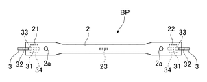
シールドマシンによりトンネルに組立てられて行くセグメントは、鉄製の場合、セグメント同士の接続が、各セグメントの両端に設けられたフランジ1においてなされる。図1は鉄製セグメントのフランジ1の部分に本発明仮設枕木BPの第一例を設置した正面図であり、図2は図1の仮設枕木BPの要部の平面図である。
Next, an embodiment of the present invention will be described with reference to the drawings.
In the case where the segments assembled in the tunnel by the shield machine are made of iron, the segments are connected to each other at flanges 1 provided at both ends of each segment. FIG. 1 is a front view in which a first example of a temporary sleeper BP of the present invention is installed on a portion of a flange 1 of an iron segment, and FIG. 2 is a plan view of a main part of the temporary sleeper BP of FIG.
シールドマシンにより掘削される穴に順次埋設されてトンネル本体に形成されていく接続されたセグメントには、工事用の各種車輌等の走行のために敷設される仮設レールR(以下、単にレールRという)を取付けるために、接続された前後のセグメントのフランジ1を主桁としてその上に本発明仮設枕木BPが設置される(図1参照)。 Connected segments that are sequentially buried in holes drilled by the shield machine and formed in the tunnel body include temporary rails R (hereinafter simply referred to as rails R) laid for traveling of various vehicles for construction and the like. 1), the temporary sleeper BP of the present invention is installed thereon with the flanges 1 of the connected front and rear segments as main girders (see FIG. 1).
本発明仮設枕木BPの第一例は、図1,図2に略示したように、鋼管の左右両端部を平面内で圧潰した平板部21,22を備えた枕木部材2と、鉄製セグメント接続部のフランジ1(以下、主桁1ともいう)における底部上面が形成する円弧面に対し弦状をなすように長さを整えた前記枕木部材2の長さ方向の両端に形成した前記平板部21,22を下から支えるように当該平板部21,22に立ち姿勢で設けた左右一対の支持ブラケット3,3を主要部材として形成されている。前記支持ブラケット3は、1枚の鋼板で形成されている。
前記平板部21,22は、圧潰前に平鋼又は鋼管による補強材21a,22aを挿入して圧潰し、当該平板部21,22を補強している。前記補強材21a,22aは、平板部21,22の全長より深く枕木部材2の内部に入っていることが好ましい。
The first example of the temporary sleeper BP of the present invention is, as schematically shown in FIG. 1 and FIG. 2, a
The
左右一対の支持ブラケット3,3は、セグメントの垂直方向の中心線に関して左右対称な形態であるが、同一部材による同一構造物であるから以下の説明は、一方(図1の左側)の支持ブラケット3について説明する。なお、図1の右側の支持ブラケット3にも同一符号を用いている。
The pair of left and
支持ブラケット3は、その上面に、前記枕木部材2の平板部21,22を載架支持するために、当該平板部21,22の厚さ分を収める一段下がった水平方向の支持面31が形成されていると共に、この仮設枕木BPに載置されるレールRにおける底部の左右の翼状張出部Ra,Rbにおける外側(セグメントの外周寄り、以下同じ。)の張出部Raを嵌合的に支持する断面略倒U状のレール保持部32を、前記支持面31の外側に備えて形成されている。
前記支持ブラケット3の下面は、該支持ブラケット3が設置されるセグメント(又はフランジ1)の内周面に沿った傾斜当接面33に形成され、その傾斜当接面33の左右両端部が曲面33aに形成されている。前記曲面33aにおいて内側(セグメントの中心寄り、以下同じ。)の曲面33aには、鉄板で補強したゴム系等による平面視板状の当接部34が設けられている。なお、前記当接部34は、セグメントに瑕が付かない、又は瑕が付いても構わない場合には省略できる。
On the upper surface of the
The lower surface of the
本発明仮設枕木BPに載置されるレールRの底部において、前記支持ブラケット3のレール保持部32に支持される外側の張出部Raと反対側の張出部Rbは、図1に示すように、枕木部材2の平板部21,22に明けられた穴2aに取付けられるボルト4a,ナット4bとこのボルト,ナット4a,4bに固定されるクリップ4cから成るレール固定具4により、枕木部材2の平板部21,22に固定される。以上によりレールRを載置する本発明仮設枕木BPの第一例を形成する。なお、レール固定具4には、規格品又は別製のレール押えのいずれかを用いることができる。
前記枕木部材2の長さ方向略中央部には、ボルト穴を備えた垂下舌片を連結片23として設け、当該枕木部材2の連結片23と前記フランジ1の底に立てたボルト穴を備えた結合片1aをボルト結合し、仮設枕木BPのずれ止めやローリング防止を補完すると共に枕木部材2にかかる荷重の支持を補うようにしている。
At the bottom of the rail R placed on the temporary sleeper BP of the present invention, the overhanging portion Rb opposite to the outer overhanging portion Ra supported by the
At a substantially central portion in the length direction of the
上記のように形成される本発明仮設枕木BPの第一例は、図1の正面図に示すような姿で鉄製セグメントの継目であるフランジ1の上に配置される。
すなわち、枕木部材2は、左右の平板部21,22に設けた支持ブラケット3,3が備えた当接部34,34において前記フランジ1の上に置かれて前記フランジ1による主桁に弦状に配置される。
つまり前記枕木部材2は、その左右両端の支持ブラケット3,3が、その傾斜当接面33に設けた当接部34,34において、接続された2つのフランジ1の上に載置され、同時に当該枕木部材2の略中央に垂下した連結片23を前記フランジ1に底部中央に設けた結合片1aにボルト結合することによって、鉄製セグメントのフランジ1の上に設置される。このようにして一次覆工のセグメントに設置された本発明仮設枕木BPは、一次覆工に伴うレールRを支持し、かつ必要に応じ二次覆工用の軌条として前記レールRをそのまま使用できる。
The first example of the temporary sleeper BP of the present invention formed as described above is arranged on the flange 1 which is a joint of the iron segments in a shape as shown in the front view of FIG.
That is, the
In other words, the
上述した本発明仮設枕木BPの第一例は、鉄製セグメントのフランジ1を主桁として鉄製セグメントに設置されるが、本発明仮設枕木BPは、図5に例示するように、RCセグメントSにもそのまま適用できるので、以下この点について述べる。 The first example of the temporary sleeper BP of the present invention described above is installed on the iron segment using the flange 1 of the iron segment as the main girder, but the temporary sleeper BP of the present invention is also provided on the RC segment S as illustrated in FIG. Since this can be applied as it is, this point is described below.
RCセグメントSは、接続部に鉄製セグメントのようなフランジ1がないので、接続されたセグメントSは内面が全体的に略フラットな円弧面を呈する。
そこで本発明仮設枕木BPの第一例は、図5に例示するように、RCセグメントSにこの仮設枕木BPを設置するとき、左右一対の支持ブラケット3,3における底部に設けた当接部34,34が、このセグメントSの内面Isに当接した態様で設置される。図5において、枕木部材2が備えた連結片23は、下端部が前記セグメントSの内面Isに当接できる長さのものである。前記連結片23は、その下端部に面状の当接部を有するもの用いることがある。
Since the RC segment S does not have a flange 1 such as an iron segment at the connection portion, the connected segment S has an arc surface whose inner surface is substantially flat as a whole.
Therefore, in the first example of the temporary sleeper BP of the present invention, as shown in FIG. 5, when the temporary sleeper BP is installed on the RC segment S, the
図5のRCセグメントSに適用した本発明仮設枕木BPでは、左右の支持ブラケット3,3の底部に設けた曲面を有する当接部34,34と連結片23の当接部が、セグメント内面Isに直接当接している。なお、連結片23の当接部を含み前記当接部は、大きな荷重に対応すると共にRCセグメントSの内表面を瑕付けないため、および該当接部に発生する錆をセグメント表面に付着させないために、例えばゴム系材料でカバーした鉄板、又は鍍金鋼板で製作したものを用いるとよい。勿論、本発明仮設枕木BPはこの構造の当接部に限られるものではない。
In the temporary sleeper BP of the present invention applied to the RC segment S of FIG. 5, the
以上の実施例は、本発明仮設枕木BPを、図1,図2,図5に例示した鋼管の両端部を圧潰して形成した平板部21,22と略中央部に垂下した連結片23を備える枕木部材2と支持ブラケット3により構成したものであったが、本発明では図3,図4に示した本発明第二例の仮設枕木BPとすることができるので、この仮設枕木BPついて以下に説明する。
In the above embodiment, the temporary sleeper BP of the present invention is made up of the
すなわち、図3,図4に示した本発明仮設枕木BPの第二例では、図1,図2,図5で説明した第一例の枕木部材2の略中央部を切り離して左右の枕木ブロック体2L,2Rに形成し、前記分離部の枕木ブロック体2L,2Rに、略中央部に垂下した連結片23を備えた枕木の長さ調節バー部材24を挿入しこれをボルト止によって接合し、仮設枕木BPの全長を調節できる本発明仮設枕木BPの第二例に形成した。このため前記長さ調節バー部材24は、その長さ方向に沿って複数のボルト穴24aを有しており、このボルト穴24aを選択して前記左右の枕木ブロック体2L,2Rに設けたボルト穴からボルトBをねじ込んで仮設枕木BPの長さをセグメントの異なる断面内径やレールゲージの違いに合わせることができるようにした。図3,図4において、図1,図2と同じ部材、同じ部位には同じ符号を用いているから説明は略す。
図6は、図3,図4により説明した鉄製セグメントに適用した長さ調節可能な本発明仮設枕木BPの第二例を、RCセグメントSに適用した例の正面図である。図6においても図1〜図5に示す例と同じ部材、同じ部位には同じ符号を用いて説明を省略する。なお、RCセグメントSに適用した図6の本発明仮設枕木BPでは、連結片の下端部がセグメント内面Is当接する長さに整えた連結片23、或はその長さに調整できる連結片23が用いられる。
That is, in the second example of the temporary sleeper BP of the present invention shown in FIGS. 3 and 4, the right and left sleeper blocks are separated by cutting off substantially the center of the
FIG. 6 is a front view of an example in which the second example of the temporary sleeper BP of the present invention, which can be applied to the iron segment described with reference to FIGS. In FIG. 6, the same members and the same parts as those in the examples shown in FIGS. In the temporary sleeper BP of FIG. 6 applied to the RC segment S, the connecting
本発明仮設枕木BPは、図5,図6により説明した、左右の支持ブラケット3を夫々に備えて中間で分離した左右の枕木ブロック体2L,2Rと枕木の長さ調節バー部材24を接合する枕木長さ調節タイプの仮設枕木BPでは、長さ調節バー部材24のボルト穴25の位置を選択して用いたり、長さ調節バー部材24の長さと連結片23の長さが種々異なるものを予め用意しておけば、小断面口径のセグメントから大断面口径のセグメントまでに適用可能な本発明仮設枕木BPの第二例で対応することができる。
In the temporary sleeper BP of the present invention, the right and left
本発明仮設枕木BPでは、枕木部材2と枕木ブロック体2L,2Rおよび長さ調節バー部材24に鋼管を使用し、枕木ブロック体2L,2Rを含む枕木部材2の両端部に平鋼または鋼管による補強材21a,22aを挿装した上でその部分をプレスにより圧潰して補強平板部21,22を有する形態であってもよい。また、枕木部材2(枕木ブロック体2L,2Rを含む)と長さ調整バー部材24には、前記鋼管のほかにL形鋼、溝型鋼、軽溝型鋼などを補強リブの使用を選択して用いることができる。図7、図8に枕木部材にL型鋼を用いて形成した本発明仮設枕木BPの第三例を示す。
In the temporary sleeper BP of the present invention, a steel pipe is used for the
図7、図8の本発明仮設枕木BPの第三例において、20はL型鋼による枕木部材で、この枕木部材20の両端部に左右一対の支持ブラケット3,3が設けられている点は、先に説明した本発明仮設枕木BPの二つの例と同じである。
図7,図8に示した仮設枕木BPでは、左右の支持ブラケット3,3がL型鋼の水平部材20Hの手前側(垂直部材20Vの反対側)に設けられていること、支持ブラケット3,3の底部の傾斜当接面33に支持ブラケット3を両面から抱持する挟持片34aを備えた断面略U状をなす当接部34が設けられていること、前記挟持片34aがボルト等のネジ材34bで支持ブラケット3に止められている点において、先の実施例の仮設枕木BPと異なっているが、他の構成は略同じである。なお、この仮設枕木BPでも枕木部材2にほぼ中央部に垂下した連結片23を有しており、該連結片23がセグメントSの内表面にある結合片1sに結合されるようになっている。
In the third example of the temporary sleeper BP of the present invention shown in FIGS. 7 and 8,
In the temporary sleeper BP shown in FIGS. 7 and 8, the left and
本発明は以上の通りであって、フランジに横桁や補強L状プレートが設けられた鉄製セグメント、或は前駆横桁等が設けられない鉄製セグメントもRCセグメントのいずれのセグメントにも適用でき、しかも、仮設枕木の設置においてセグメントへの溶接を行わないため、用済み後は容易に取外しできて再使用が可能なシールドトンネル工事用の仮設枕木を提供することができる。 The present invention is as described above, and an iron segment in which a cross beam or a reinforcing L-shaped plate is provided in a flange, or an iron segment in which a precursor cross beam or the like is not provided can be applied to any segment of the RC segment, Moreover, since welding to the segments is not performed when installing the temporary sleepers, it is possible to provide a temporary sleeper for shield tunnel construction that can be easily removed after use and can be reused.
S RCセグメント
R 仮設レール
1 鉄製セグメントのフランジ(主桁)
2 枕木部材
2L,2R 枕木ブロック体
21,22 平板部
23 垂下した連結片
3 支持ブラケット
31 平板部の支持面
32 レール保持部
33 傾斜当接面
34 曲面を有する当接部
4 レール固定具
S RC segment R Temporary rail 1 Iron segment flange (main girder)
2
Claims (6)
Priority Applications (1)
| Application Number | Priority Date | Filing Date | Title |
|---|---|---|---|
| JP2016178139A JP6644657B2 (en) | 2016-09-13 | 2016-09-13 | Temporary sleepers for shield tunnel construction |
Applications Claiming Priority (1)
| Application Number | Priority Date | Filing Date | Title |
|---|---|---|---|
| JP2016178139A JP6644657B2 (en) | 2016-09-13 | 2016-09-13 | Temporary sleepers for shield tunnel construction |
Publications (2)
| Publication Number | Publication Date |
|---|---|
| JP2018044309A JP2018044309A (en) | 2018-03-22 |
| JP6644657B2 true JP6644657B2 (en) | 2020-02-12 |
Family
ID=61692908
Family Applications (1)
| Application Number | Title | Priority Date | Filing Date |
|---|---|---|---|
| JP2016178139A Active JP6644657B2 (en) | 2016-09-13 | 2016-09-13 | Temporary sleepers for shield tunnel construction |
Country Status (1)
| Country | Link |
|---|---|
| JP (1) | JP6644657B2 (en) |
Families Citing this family (3)
| Publication number | Priority date | Publication date | Assignee | Title |
|---|---|---|---|---|
| JP6751988B2 (en) * | 2017-03-23 | 2020-09-09 | 株式会社奥村組 | Fixed structure of sleepers in the shield mine |
| CN112411268B (en) * | 2020-12-04 | 2022-03-04 | 中建八局轨道交通建设有限公司 | Shield electric locomotive marshalling track system self-adapting to duct piece radian and construction method thereof |
| CN113550181A (en) * | 2021-07-07 | 2021-10-26 | 上海市基础工程集团有限公司 | Shield tunnel is fallen to ground sleeper for rail transport vechicle |
Family Cites Families (7)
| Publication number | Priority date | Publication date | Assignee | Title |
|---|---|---|---|---|
| JPS54174107U (en) * | 1978-05-30 | 1979-12-08 | ||
| JP2788955B2 (en) * | 1990-08-31 | 1998-08-20 | 清水建設株式会社 | Track laying method and track laying device in shield construction |
| JP2910502B2 (en) * | 1993-05-20 | 1999-06-23 | 株式会社大林組 | RC segment lining and RC segment |
| JP3725962B2 (en) * | 1997-03-31 | 2005-12-14 | 株式会社イズミ | Temporary sleeper structure for shield tunnel construction |
| JP3928987B2 (en) * | 1997-06-02 | 2007-06-13 | 株式会社イズミ | Tunnel sleepers |
| EP2327835A1 (en) * | 2009-11-25 | 2011-06-01 | Voestalpine Railpro BV | Sleeper for a railroad section, railroad section and method of laying down a railroad |
| JP2014009558A (en) * | 2012-07-02 | 2014-01-20 | Ohbayashi Corp | Temporary sleeper for shield tunnel work |
-
2016
- 2016-09-13 JP JP2016178139A patent/JP6644657B2/en active Active
Also Published As
| Publication number | Publication date |
|---|---|
| JP2018044309A (en) | 2018-03-22 |
Similar Documents
| Publication | Publication Date | Title |
|---|---|---|
| KR101518682B1 (en) | Stripping Deck | |
| JP6644657B2 (en) | Temporary sleepers for shield tunnel construction | |
| JP6180376B2 (en) | Main girder provision method in composite girder floor slab replacement method, composite girder floor slab replacement method, and main girder provision structure in composite girder floor slab replacement method | |
| JP2014009558A (en) | Temporary sleeper for shield tunnel work | |
| KR101665482B1 (en) | Method for Constructing Long Span Continuous Bridge of Spliced Prestressed Concrete Girders without Temporary Supports | |
| JP4540632B2 (en) | Erection girder | |
| JP2014141997A (en) | Pipeline laying method | |
| US20210156251A1 (en) | Adjustable Lattice Girder | |
| JP5850734B2 (en) | Non-open-cut method segment and shield tunnel and non-open-cut method | |
| JP2014181439A (en) | Form device for prismatic concrete structure and construction method using the same | |
| JP3725962B2 (en) | Temporary sleeper structure for shield tunnel construction | |
| CN112281916A (en) | Large-axillary-angle single-side-wall movable formwork for subway engineering | |
| JP7306619B2 (en) | Main pipe conveying device into sheath pipe | |
| JP7231434B2 (en) | Installation method of reinforcing bar assembly for tunnel secondary lining | |
| JP6432786B2 (en) | Beam material load bearing structure and beam material repair method | |
| JP2004183273A (en) | Tunnel structure | |
| JP7008437B2 (en) | PCa floor slab transportation and installation jig for forklift trucks and PCa floor slab transportation and installation method using it | |
| JP4136959B2 (en) | "How to build underground structures and installation girder" | |
| US8613567B2 (en) | Clip and method for joining steel ribs used as tunnel liner supports | |
| JP2002167969A (en) | Pipe-constructed frame with carriage | |
| JP6271801B1 (en) | Road bridge inspection deck and road bridge inspection deck construction method | |
| CN111472783B (en) | Shield tunneling machine split initial lengthened pipeline extending device and application method | |
| JP6441842B2 (en) | Box roof cylinder | |
| JP3803036B2 (en) | Rail for construction in tunnel excavation | |
| KR20080111578A (en) | The support material for a tunnel and support structure |
Legal Events
| Date | Code | Title | Description |
|---|---|---|---|
| A621 | Written request for application examination |
Free format text: JAPANESE INTERMEDIATE CODE: A621 Effective date: 20180502 |
|
| A977 | Report on retrieval |
Free format text: JAPANESE INTERMEDIATE CODE: A971007 Effective date: 20181212 |
|
| A131 | Notification of reasons for refusal |
Free format text: JAPANESE INTERMEDIATE CODE: A131 Effective date: 20190115 |
|
| A521 | Written amendment |
Free format text: JAPANESE INTERMEDIATE CODE: A523 Effective date: 20190307 |
|
| RD04 | Notification of resignation of power of attorney |
Free format text: JAPANESE INTERMEDIATE CODE: A7424 Effective date: 20190315 |
|
| A02 | Decision of refusal |
Free format text: JAPANESE INTERMEDIATE CODE: A02 Effective date: 20190618 |
|
| A521 | Written amendment |
Free format text: JAPANESE INTERMEDIATE CODE: A523 Effective date: 20190917 |
|
| A521 | Written amendment |
Free format text: JAPANESE INTERMEDIATE CODE: A821 Effective date: 20190917 |
|
| A911 | Transfer of reconsideration by examiner before appeal (zenchi) |
Free format text: JAPANESE INTERMEDIATE CODE: A911 Effective date: 20191122 |
|
| TRDD | Decision of grant or rejection written | ||
| A01 | Written decision to grant a patent or to grant a registration (utility model) |
Free format text: JAPANESE INTERMEDIATE CODE: A01 Effective date: 20191217 |
|
| A61 | First payment of annual fees (during grant procedure) |
Free format text: JAPANESE INTERMEDIATE CODE: A61 Effective date: 20200108 |
|
| R150 | Certificate of patent or registration of utility model |
Ref document number: 6644657 Country of ref document: JP Free format text: JAPANESE INTERMEDIATE CODE: R150 |
|
| S111 | Request for change of ownership or part of ownership |
Free format text: JAPANESE INTERMEDIATE CODE: R313117 |
|
| R360 | Written notification for declining of transfer of rights |
Free format text: JAPANESE INTERMEDIATE CODE: R360 |
|
| R360 | Written notification for declining of transfer of rights |
Free format text: JAPANESE INTERMEDIATE CODE: R360 |
|
| R371 | Transfer withdrawn |
Free format text: JAPANESE INTERMEDIATE CODE: R371 |
|
| S111 | Request for change of ownership or part of ownership |
Free format text: JAPANESE INTERMEDIATE CODE: R313117 |
|
| R350 | Written notification of registration of transfer |
Free format text: JAPANESE INTERMEDIATE CODE: R350 |