JP6637584B2 - Cooker - Google Patents
Cooker Download PDFInfo
- Publication number
- JP6637584B2 JP6637584B2 JP2018242358A JP2018242358A JP6637584B2 JP 6637584 B2 JP6637584 B2 JP 6637584B2 JP 2018242358 A JP2018242358 A JP 2018242358A JP 2018242358 A JP2018242358 A JP 2018242358A JP 6637584 B2 JP6637584 B2 JP 6637584B2
- Authority
- JP
- Japan
- Prior art keywords
- infrared sensor
- temperature
- heating chamber
- heating
- heated
- Prior art date
- Legal status (The legal status is an assumption and is not a legal conclusion. Google has not performed a legal analysis and makes no representation as to the accuracy of the status listed.)
- Active
Links
Images


Landscapes
- Electric Ovens (AREA)
Description
本発明は加熱調理器に係り、特に加熱室に入れて加熱される被加熱物(食品)の温度を測定するための赤外線センサを備えた加熱調理器に関する。 The present invention relates to a cooking device, and more particularly to a cooking device provided with an infrared sensor for measuring the temperature of an object (food) to be heated in a heating chamber.
特許文献1と特許文献2で知られている公知技術では、加熱室内の食品の温度を検知する赤外線センサは、加熱室の全域の温度を検出できるように、直線状に整列した複数の赤外線検出素子を有した赤外線センサを加熱室の奥壁面もしくは天面と奥壁面との角部に設け、前記赤外線センサを加熱室の前後方向は、前記直線状に整列した複数の赤外線検出素子で同時に複数個所の温度を検出し、前記加熱室の左右方向は、前記赤外線センサを左右に揺動し、左右方向に赤外線センサを揺動してスキャンすることで加熱室内の複数の温度を測定するものである。
According to the known technology disclosed in Patent Document 1 and
また、特許文献3は、直線状に整列した複数の赤外線検出素子を設けた赤外線センサを右側面に取り付け、加熱室の奥側から手前側にスキャンして加熱室内の複数の温度を測定するものである。
Further,
上記特許文献1と2に示す赤外線センサは、加熱室の底面に載置された被加熱物の温度を検出する時、加熱室の奥壁面上部の斜め上から赤外線センサを左右方向に揺動して温度測定することになる。
When detecting the temperature of an object to be heated placed on the bottom surface of the heating chamber, the infrared sensors disclosed in
その場合、前記赤外線センサは、加熱室の前後方向には、直線状に整列した複数の赤外線検出素子によって前記斜め上から検出する検出角度は固定されているため検出箇所は制限される。左右方向については、前記直線状に整列した複数の赤外線検出素子を設けた赤外線センサを左右に揺動して加熱室内の複数個所の温度を逐次測定するため、左右方向には測定箇所を好みに応じて測定点を荒くも細かくも測定可能である。 In this case, the detection position of the infrared sensor is limited in the front-rear direction of the heating chamber because the detection angle of the infrared sensor that is detected obliquely from above by a plurality of linearly aligned infrared detection elements is limited. In the left-right direction, the infrared sensor provided with the plurality of infrared detection elements aligned in a straight line is swung right and left to sequentially measure the temperature at a plurality of locations in the heating chamber. Accordingly, the measurement point can be roughly or finely measured.
また、上記特許文献3に示す赤外線センサは、加熱室の底面に載置された被加熱物の温度を検出する時、加熱室の側面上部の斜め上から赤外線センサを前後(手前側と奥側)方向に揺動して温度測定することになる。
When detecting the temperature of an object to be heated placed on the bottom surface of the heating chamber, the infrared sensor disclosed in
その場合、前記赤外線センサは、加熱室の左右方向には、直線状に整列した複数の赤外線検出素子によって前記斜め上から検出する検出角度は固定されているため検出箇所は制限さる。前後方向には、前記直線状に整列した複数の赤外線検出素子を設けた赤外線センサを前後に揺動して加熱室内の複数個所の温度を逐次測定するため、前後方向には測定箇所を好みに応じて測定点を荒くも細かくも測定可能である。 In that case, the detection position of the infrared sensor is limited in the left-right direction of the heating chamber, since the detection angle for obliquely detecting the infrared sensor by a plurality of linearly arranged infrared detection elements is fixed. In the front-back direction, the infrared sensor provided with the plurality of infrared detection elements aligned in a straight line swings back and forth to sequentially measure the temperature at a plurality of locations in the heating chamber. Accordingly, the measurement point can be roughly or finely measured.
ここで、加熱室の中央部に載置したコップに入れた被加熱物(例えば牛乳)の温度を検出する場合、コップに入れられた被加熱物が赤外検出素子の視野角内に入るように、コップの上から被加熱物を覗き見る方向に赤外線素子の向きを向ける必要が有る。 Here, if it detects the temperature of the object to be heated placed in a cup placed on the central portion of the heating chamber (e.g. milk), the object to be heated which is placed on the cup enters the viewing angle of the infrared detection element As described above, it is necessary to point the infrared element in a direction in which the object to be heated is viewed from above the cup.
また、斜め上方から被加熱物の温度を検出する場合は、高さの異なる容器に入れられた被加熱物の温度を検知するには、前記容器毎に異なる高さに位置する開口部から被加熱物の温度を検出できるように、前記容器の高さに温度を測定できる構成にする必要が有る。 In the case of detecting the temperature of the heated object obliquely from above is to test knowledge the temperature of the object to be heated is placed in a different container heights, from the opening positioned at different heights in the respective container so as to detect the temperature of the heated object, should there be a configuration capable of measuring the temperature at the height of the container.
前述した各特許文献に示されている赤外線センサの構造では、被加熱物の温度を検出するのに温度の影響を受ける場合が有る。 In the structure of the infrared sensor disclosed in each of the aforementioned patent documents, the temperature of the object to be heated may be affected by the temperature .
本発明は、上記の課題を解決するためになされたもので、被加熱物を入れて加熱するとともに、上方に観測窓を有する加熱室と、前記被加熱物を加熱する加熱手段と、前記被加熱物の温度を検知する赤外線センサと、該赤外線センサを収めるとともに、該赤外線センサを臨ませる窓部と、この窓部以外に外形が円弧状となる円弧状部を有するユニットケースと、該ユニットケースの円弧状部に対向する円弧状の内面を備え、該円弧状の内面に前記観測窓を開口した観測部と、前記赤外線センサの検知温度に基づき前記加熱手段を制御する制御手段と、を備え、前記ユニットケースを回動させることにより、前記窓部を前記観測窓に臨ませる状態と、前記円弧状部を前記観測窓に臨ませる状態をとるものである。 The present invention has been made to solve the above problems, as well as heat putting an object to be heated, a heating chamber having an upwardly observation window, a heating means for heating the object to be heated, before Symbol an infrared sensor for detecting the temperature of the heated object, together fit the infrared sensor, and a unit case having a window for exposing the infrared sensor, an arcuate portion outer shape other than the window portion is arcuate, the An observation section having an arc-shaped inner surface facing the arc-shaped portion of the unit case, the observation window having the observation window opened on the arc-shaped inner surface, and a control means for controlling the heating means based on a detection temperature of the infrared sensor, And rotating the unit case so that the window portion faces the observation window and the arc-shaped portion faces the observation window.
本発明によれば、被加熱物の温度検出に優れ、さらに赤外線センサは温度の影響に対しても配慮された加熱調理器とすることができる。 According to the present invention, excellent temperature detection of the object to be heated, further infrared sensor may be a heating cooker which is also considered for the effect of temperature.
以下図面を参照して本発明の実施例を説明する。 Hereinafter, embodiments of the present invention will be described with reference to the drawings.
以下、本発明の実施例を添付図面に従って説明する。 Hereinafter, embodiments of the present invention will be described with reference to the accompanying drawings.
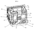
図1から図3は、本実施例の主要部分を示すもので、図1は加熱調理器本体を前面側から見た斜視図、図2は同本体の外枠を除いた状態で後方側から見た斜視図、図3は図1のA−A断面図である。 1 to 3 show main parts of the present embodiment. FIG. 1 is a perspective view of a heating cooker main body viewed from the front side, and FIG. 2 is a rear view of the main body without the outer frame. FIG. 3 is a sectional view taken along line AA of FIG.
図において、加熱調理器の本体1は、加熱室28の中に加熱する食品を入れ、マイクロ波やヒータの熱、過熱水蒸気を使用して食品を加熱調理する。
In the figure, a main body 1 of a heating cooker puts a food to be heated in a
ドア2は、加熱室28の内部に食品を出し入れするために開閉するもので、ドア2を閉めることで加熱室28を密閉状態にし、食品を加熱する時に使用するマイクロ波の漏洩を防止し、ヒータの熱や過熱水蒸気を封じ込め、効率良く加熱することを可能とする。
The
取っ手9は、ドア2に取り付けられ、ドア2の開閉を容易にするもので、手で握りやすい形状になっている。
The handle 9 is attached to the
ガラス窓3は、調理中の食品の状態が確認できるようにドア2に取り付けられており、ヒータ等の発熱による高温に耐えるガラスを使用している。
The
入力手段71は、ドア2の前面下側の操作パネル4に設けられ、マイクロ波加熱やヒータ加熱等の加熱手段や加熱する時間等と加熱温度の入力するための操作部6と、操作部6から入力された内容や調理の進行状態を表示する表示部5とで構成されている。 外枠7は、加熱調理器の本体1の上面と左右側面を覆うキャビネットである。
The
水タンク42は、加熱水蒸気を作るのに必要な水を溜めておく容器であり、加熱調理器の本体1の前面下側に設けられ、本体1の前面から着脱可能な構造とすることで給水および排水が容易にできるようになっている。
The
後板10は、前記したキャビネットの後面を形成するものであり、上部に外部排気ダクト18が取り付けられ、食品から排出した蒸気や本体1の内部の部品を冷却した後の冷却風(廃熱)39を外部排気ダクト18の外部排気口8から排出する。
The
機械室20は、加熱室底面28aと本体1の底板21との間の空間部に設けられ、底板21上には食品を加熱するためのマグネトロン33、マグネトロン33に接続された導波管47、制御基板23、その他後述する各種部品、これらの各種部品を冷却するファン装置15等が取り付けられている。 加熱室底面28aは、略中央部が凹状に窪んでおり、その中に回転アンテナ26が設置され、マグネトロン33より放射されるマイクロ波エネルギーが導波管47、回転アンテナ26の出力軸46aが貫通する開孔部47aを通して回転アンテナ26の下面に流入し、該回転アンテナ26で拡散されて加熱室28内に放射される。回転アンテナ26の出力軸46aは回転アンテナ駆動手段46に連結されている。
The
ファン装置15は、底板21に取り付けた冷却モータに取り付けられた冷却ファンとで構成する。このファン装置15によって発生する冷却風39は、機械室20内の自己発熱するマグネトロン33やインバータ基板(図示無し)、重量検出手段25c,25bなどを冷却する。また、加熱室28の外側と外枠7の間および前記したように熱風ケース11aと後板10の間を流れ、外枠7と後板10を冷却しながら外部排気ダクト18の外部排気口8より排出される。さらに、後述する熱風モータ13を冷却するためのダクト16aと、後述する赤外線ケース48内に収められた赤外線ユニット50を冷却するためのダクト16bが設けられ、赤外線ユニット50を冷却した冷却風39は、加熱室28内の排熱(水蒸気など)を廃棄する排気ダクト28eの反対側から排出された後外部排気ダクト18より外に排出される。
The
加熱室28の後部には、熱風ユニット11が取り付けられ、該熱風ユニット11内には加熱室28内の空気を効率良く循環させる熱風ファン32が取り付けられ、加熱室後部壁面28bには空気の通り道となる熱風吸気孔31と熱風吹出し孔30が設けられている。
A
熱風ファン32は、熱風ケース11aの外側に取り付けられた熱風モータ13の駆動により回転し、熱風ヒータ14で循環する空気を加熱する。
The
また、熱風ユニット11は、加熱室奥壁面28bの後部側に熱風ケース11aを設け、加熱室奥壁面28bと熱風ケース11aとの間に熱風ファン32とその外周側に位置するように熱風ヒータ14を設け、熱風ケース11aの後側に熱風モータ13を取り付け、そのモータ軸を熱風ケース11aに設けた穴を通して熱風ファン32と連結している。
The
熱風モータ13は、加熱室28や熱風ヒータ14からの熱によって温度上昇するため、それを防ぐために、熱風モータカバー17によって囲い、略筒状に形成されてダクト16aを熱風ケース11aと後板10との間に位置し、ダクト16aの上端開口部を熱風モータカバー17の下面に接続し、下端開口部をファン装置15の吹出し口に接続し、ファン装置15からの冷却風39の一部を熱風モータカバー17内に取り入れるようにしている。
Since the temperature of the
加熱室28の加熱室天面28cの裏側には、ヒータよりなるグリル加熱手段12が取り付けられている。グリル加熱手段12は、マイカ板にヒータ線を巻き付けて平面状に形成し、加熱室28の天面裏側に押し付けて固定し、加熱室28の天面を加熱して加熱室28内の食品を輻射熱によって焼くものである。
On the back side of the heating chamber
また、加熱室28の加熱室天面28cの奥側には後述する赤外線ユニット50が設けられ、赤外線ユニット50を冷却するために赤外線ケース48にて覆い、略筒状に形成されてダクト16bを熱風ケース11aと後板10との間に位置し、ダクト16bの上端開口部を赤外線ケース48の側面に接続し、下端開口部を熱風モータカバー17上面と接続し、ファン装置15からの冷却風39の一部を取り入れるようにしている。
Further, an
また、加熱室底面28aには、複数個の重量検出手段25、例えば前側左右に右側重量センサ25b、左側重量センサ(図示無し)、後側中央に奥側重量センサ25cが設けられ、その上にテーブルプレート24が載置されている。 テーブルプレート24は、食品を載置するためのもので、ヒータ加熱とマイクロ波加熱の両方に使用できるように耐熱性を有し、かつ、マイクロ波の透過性が良い材料で成形されている。
Further, a plurality of weight detecting means 25, for example, a
ボイラー43は、熱風ユニット11の熱風ケース11aの外側面に取り付けられ、飽和水蒸気を熱風ユニット11内に臨ませ、熱風ユニット11内に噴出した飽和水蒸気は熱風ヒータ14によって加熱され過熱水蒸気となる。
The
ポンプ手段87は、水タンク42の水をボイラー43まで汲み上げるもので、ポンプとポンプを駆動するモータで構成される。ボイラー43への給水量の調節はモータのON/OFFの比率で決定する。
The pump means 87 pumps the water in the
次に、図4〜図7を用いて赤外線ユニットについて詳細を説明する。 Next, the infrared unit will be described in detail with reference to FIGS.
51はモータで、モータ51の向きは、回転軸51aと加熱室奥壁面28bと並行となるように取り付けられている。そして、回転軸51aが後述する筒状のユニットケース54を回転(駆動)させることで、ユニットケース54に収めた赤外線センサ52を搭載した基板53を回転させて赤外線センサ52のレンズ部52aの向きを加熱室底面28aの奥側(加熱室奥壁面28b側)から加熱室開口部28dの高さ方向に下方から30%程度までの範囲を回転移動して温度を検出できるようにしている。モータ51はステッピングモータを使用し制御基板23に設けられた制御部の制御によって回転軸51aを正転、逆転、また回転角度を好みに動作可能となっている。
A
52は赤外線センサで、赤外線検出素子(例えばサーモパイル)を複数個設けたもので、ここでは、回転軸51aの鉛直方向に一列に8素子整列した赤外線センサを使用している。そのため、加熱室底面28aの左右方向は一度に前記複数個所の温度の検出が可能であり、加熱室28の奥側(加熱室奥壁面28b側)から前側(ドア2側)にかけては、赤外線センサ52を回転させることで加熱室底面28aの全域の温度を検出するものである。
54は筒状のユニットケースで、最大径部に基板53を配置し赤外線センサ52のレンズ部52aを臨ませる窓部54aを設けている。また、ユニットケース54の材料にはカーボンを含ませることでユニットケース54の特性を導電材とすることで外来ノイズのユニットケース54内への侵入を防止している。
55は金属板から成るシャッタである。シャッタ55は、赤外線センサ52を使用しない時に後述する観測窓44aを閉じるものである(図7参照)。また加熱室28の温度がユニットケース54に伝わるのを防止するために、ユニットケース54の外周に冷却風を流せるようにユニットケース54の外周に沿って隙間を設けた風路55cを形成するようにシャッタ55を配置し、前記風路55cに冷却風39流す出入り口となる開口55aと開口55bを設けている。
56は位置決め凸部で、赤外線センサ52の検知点を基準位置(図4の検知点a)に示すように前記制御部がモータ51の回転を制御した時、赤外線センサ52の検知点の基準位置を補正できるように、シャッタ55によって観測窓44aを閉じた時に、位置決め凸部56が赤外線ケース48に設けられたストッパ(図示無し)に当接させた状態で回転軸51aをスリップさせることで、前記制御部の制御する基準位置と赤外線センサ52の検知する基準位置となる検知点aの位置を補正することができる。
44は加熱室28の内方向に突出した円弧状の観測部で、回転軸51aの回転中心と筒状のユニットケース54の中心とユニットケース54の外周に沿って設けられて円弧状に曲げられたシャッタ55の円弧の中心と円弧状の観測部44の各中心位置は全て同一位置となっている。44aは観測部44に設けた観測窓で、赤外線センサ52の検出する視野範囲となる範囲を開口している。また、マイクロ波加熱時に観測窓44aからのマイクロ波漏洩を防止するために、観測窓44aの周囲外側には立上壁(バーリング)44bを2mm程度設けている。
観測部44を加熱室28の内側に突出させることで、最低限の狭い観測窓開口範囲で広範囲の温度検知が可能となる。
By protruding the
49は凸部であり、加熱室天面28cから赤外線ケース48と赤外線ユニット50を離すもので、加熱室天面28cとの接触を凸部49のみとすることで加熱時にグリル加熱手段12や熱風ユニット11などのヒータによって加熱された加熱室天面28cの温度が赤外線ユニット50に伝わりにくいようにしている。
次に被加熱物の温度を検出する動作について説明する。 Next, the operation of detecting the temperature of the object to be heated will be described.
被加熱物(牛乳)60cの入っている上方が開口した容器の例としてコップ60を加熱室底面28aに設けられているテーブルプレート24に載置して加熱を開始した時、マグネトロン33が安定発信する1〜2秒間はシャッタ55にて観測窓44aを閉じて(図7参照)マグネトロン33の発信開始時の不安定発信によるノイズが赤外線センサ52に入り込むのを防止する。
When the
マグネトロン33の発信が安定した後に、前記制御手段はモータ51の回転軸51aを基準位置に回転するように制御する。回転軸51aが基準位置へと回転することでユニットケース54も回転し、赤外線センサ52のレンズ部52aの向きも基準位置の検知点aを検知できる位置に回転(図4,図5参照)する。この時、冷却風39は赤外線センサ52のレンズ部52aを流れて観測窓44aから加熱室28へと流れるので、レンズ部52aへの汚れ付着を防止している。
After the transmission of the
ユニットケース54を回転することで、被加熱物60cの温度の検出は前述した基準位置(検知点a)からテーブルプレート24の検知点b、検知点cへと進み、さらにユニットケース54が回転するとコップ60の外側の温度を高さ方向に検知し、検知点dから検知点eの温度を検知する。検知点がコップ60の開口部の頂点に達した後は、被加熱物60cの表面の温度を検知点fで検知し、次にコップ60の内側の温度を検知点gで検知し、次にテーブルプレート24の温度を検知点hで検知し、終点のドア2の温度を検知点iで検知する。
By rotating the
検知点a〜検知点iの温度検知範囲の温度の検知は、ユニットケース54を回転する往復時の両方で行っても良いし、一度終点まで温度検知を行った後、再度基準位置に戻ってから再び検知点a〜検知点iと順次行っても良い。温度の検知数は好みに変えられ、前述した検知点a〜検知点iは、説明上の例である。
The detection of the temperature in the temperature detection range from the detection point a to the detection point i may be performed during both reciprocating rotations of the
また、温度の検知はモータ51を回転した状態で検出しても良いし、温度を検知している間はモータ51の回転を止めて検知し、検知した後に回転を行っても良い。ただし、正確に温度を検知したい時は回転を止めて測定する方が良い。例えば、加熱初めは、ユニットケース54を回転しながら温度を検出し、被加熱物60cが加熱され、温度の上昇を検出した後に、温度上昇している付近の検知点をユニットケース54の回転を細かく止めて被加熱物60cの温度を多く検知してもよい。そうすることで、背の高いコップ60に入れられた被加熱物60cの温度を検知する場合、被加熱物60cの温度を直接検知できる範囲が狭くなるので、狭い範囲の温度検知に有効である。
Further, the temperature may be detected while the
また、温度の検知点iの終点がドア2の温度を検知する位置まで設けているのは、被加熱物60cを入れたコップ60が加熱室28の手前側に載置された場合でも、コップ60の上部開口部から被加熱物60cの表面温度を検知できる位置まで拡大しているためである。
Further, the reason why the end point of the temperature detection point i is provided to the position where the temperature of the
さらに、重量検出手段25による重量情報と赤外線センサ52による検知した温度分布情報から重量情報が軽く温度分布の温度上昇が広範囲に認められるときは、被加熱物60cが薄くて軽いものと判断できる。また、重量情報が重く温度分布の温度上昇が狭い範囲のみに認められるときは、例えば背の高いコップ60に被加熱物60cが入れられていると判断できる。
Further, when the weight information is light from the weight information by the weight detecting means 25 and the temperature distribution information detected by the
本実施例では、加熱室天面28cに赤外線ユニット50を設けたが、赤外線ユニット50の取り付ける位置は、加熱室奥壁面28b、加熱室左壁面、加熱室右壁面のいずれかの上方に取り付けられれば良く、加熱室奥壁面28bに取り付けた時は、モータ51の向きは、回転軸51aと加熱室奥壁面28bと並行となるように取り付け、ユニットケース54の回転は、ユニットケース54に収めた赤外線センサ52のレンズ部52aの向きが加熱室底面28aの奥側(加熱室奥壁面28b側)から加熱室開口部28dの高さ方向に下方から30%程度までの範囲を回転移動して温度を検知できるようにする。また、加熱室左壁面に取り付けた時は、モータ51の向きは、回転軸51aと加熱室左壁面と並行となるように取り付け、ユニットケース54の回転は、ユニットケース54に収めた赤外線センサ52のレンズ部52aの向きが加熱室底面28aの左側(加熱室左壁面側)から加熱室底面28aの右側(加熱室右壁面)の高さ方向に下方から30%程度までの範囲を回転移動して温度を検知できるようにする。そうすることで右側においたコップ60に入れられた被加熱物60cの温度を検知できる。加熱室右壁面に取り付けた時も同様の考え方で被加熱物の温度を検知可能である。
In the present embodiment, the
また、加熱室天面28cの左側、右側、手前側に赤外線ユニット50を取り付けた場合でも同様の考えに基づいて設置すれば、被加熱物60cの温度を正確に検知可能である。
Further, even when the
また、被加熱物60cを載置する加熱室底面28aの前後方向の長さと左右方向の長さの関係において、本実施例の温度検知を行う場合は、長さの短い前後方向に赤外線センサ52を回転させる方が、コップ60に入れられた被加熱物60cの温度を検知するのに向いている。
Further, in the case of performing the temperature detection according to the present embodiment in the relationship between the length in the front-rear direction and the length in the left-right direction of the
さらに、本実施例では、コップ60に入れた被加熱物60cの温度検知の方法を詳細説明したが、容器を使用しない被加熱物60cがブロック状の大きな塊の場合でも、ブロック状の被加熱物60cの側面の高さ方向と上面の温度を検知できるため、被加熱物60cの温度分布を詳細に検知することが可能となる。
Further, in this embodiment, the method of detecting the temperature of the
上記した本実施例によれば、容器の高さに左右される事無く被加熱物の温度検出に優れ、さらに赤外線センサは温度の影響や電波漏れに対しても配慮された加熱調理器とすることができる。以上要するに本発明は、「被加熱を入れて加熱する加熱室と、前記被加熱物を加熱する加熱手段と、前記被加熱物の上方斜めより該被加熱物の表面温度を検知する赤外線センサと、前記被加熱物の側面の高さ方向に温度を検知するように前記赤外線センサを駆動するモータと、前記赤外線センサの検知温度に基づき前記加熱手段を制御する制御手段と、を備えたことを特徴とする加熱調理器。」のように構成したものである。さらに本発明においては、「前記赤外線センサは、観測窓を介して前記被加熱物の温度を検知するものであり、前記赤外線センサを使用しないときに前記観測窓を閉じるシャッタを備えたことを特徴とする加熱調理器」のように構成したものである。また本発明は、「加熱物を入れて加熱する加熱室と、前記被加熱物を加熱する加熱手段と、該加熱室の奥側に設けられた赤外線ユニットと、該赤外線ユニット内に収納され、前記被加熱物の上方斜めより該被加熱物の表面温度を検知する赤外線センサと、前記被加熱物の側面の高さ方向に温度を検知するように前記赤外線センサを駆動するモータと、前記赤外線センサの検知温度に基づき前記加熱手段を制御する制御手段と、前記赤外線ユニットに冷却風を導く冷却手段と、を備えたことを特徴とする加熱調理器。」のように構成したものである。さらに本発明においては、「前記赤外線センサは、観測窓を介して前記被加熱物の温度を検知するものであり、前記赤外線センサを使用しないときに前記観測窓を閉じるシャッタを備えるとともに、前記赤外線センサを使用しないときに前記シャッタと前記赤外線センサとの間に前記冷却風を導く風路を形成している加熱調理器」ように構成したものである。 According to the above-described embodiment, the temperature of an object to be heated is excellently detected without being affected by the height of the container, and the infrared sensor is a heating cooker that is also considered for the influence of temperature and radio wave leakage. be able to. In summary, the present invention relates to a heating chamber that heats the object to be heated, a heating unit that heats the object to be heated, and an infrared sensor that detects the surface temperature of the object to be heated obliquely from above the object to be heated. A motor that drives the infrared sensor to detect a temperature in a height direction of a side surface of the object to be heated, and a control unit that controls the heating unit based on a temperature detected by the infrared sensor. A characteristic heating cooker. " Further, in the present invention, "the infrared sensor detects the temperature of the object to be heated through an observation window, and includes a shutter for closing the observation window when the infrared sensor is not used. Heating cooker ". Further, the present invention provides a heating chamber for heating the object to be heated, a heating unit for heating the object to be heated, an infrared unit provided on the back side of the heating chamber, and housed in the infrared unit. An infrared sensor that detects a surface temperature of the object to be heated from obliquely above the object to be heated, a motor that drives the infrared sensor to detect a temperature in a height direction of a side surface of the object to be heated, and an infrared sensor. A cooking device comprising: a control unit that controls the heating unit based on a temperature detected by a sensor; and a cooling unit that guides cooling air to the infrared unit. " Further, in the present invention, "the infrared sensor detects the temperature of the object to be heated through an observation window, and includes a shutter that closes the observation window when the infrared sensor is not used; A heating cooker that forms an air passage for guiding the cooling air between the shutter and the infrared sensor when a sensor is not used.
1 加熱調理器
44 観測部
48 赤外線ケース
49 凸部
50 赤外線ユニット
51 モータ
52 赤外線センサ
54 ユニットケース
55 シャッタ
1
Claims (6)
前記被加熱物を加熱する加熱手段と、
前記被加熱物の温度を検知する赤外線センサと、
該赤外線センサを収めるとともに、該赤外線センサを臨ませる窓部と、この窓部以外に外形が円弧状となる円弧状部を有するユニットケースと、
該ユニットケースの円弧状部に対向する円弧状の内面を備え、該円弧状の内面に前記観測窓を開口した観測部と、
前記赤外線センサの検知温度に基づき前記加熱手段を制御する制御手段と、を備え、
前記ユニットケースを回動させることにより、前記窓部を前記観測窓に臨ませる状態と、前記円弧状部を前記観測窓に臨ませる状態をとることを特徴とする加熱調理器。 A heating chamber having an observation window above and heating the object to be heated,
Heating means for heating the object to be heated ,
An infrared sensor for detecting the temperature of the pre-Symbol object to be heated,
A unit case that accommodates the infrared sensor and has a window portion facing the infrared sensor and an arc-shaped portion having an outer shape other than the window portion.
An observation unit having an arc-shaped inner surface facing the arc-shaped portion of the unit case, and having the observation window opened in the arc-shaped inner surface;
Control means for controlling the heating means based on the temperature detected by the infrared sensor,
A heating cooker characterized by taking a state in which the unit case is rotated so that the window portion faces the observation window and a state in which the arc-shaped portion faces the observation window.
Priority Applications (1)
| Application Number | Priority Date | Filing Date | Title |
|---|---|---|---|
| JP2018242358A JP6637584B2 (en) | 2018-12-26 | 2018-12-26 | Cooker |
Applications Claiming Priority (1)
| Application Number | Priority Date | Filing Date | Title |
|---|---|---|---|
| JP2018242358A JP6637584B2 (en) | 2018-12-26 | 2018-12-26 | Cooker |
Related Parent Applications (1)
| Application Number | Title | Priority Date | Filing Date |
|---|---|---|---|
| JP2015051616A Division JP6461656B2 (en) | 2015-03-16 | 2015-03-16 | Cooker |
Related Child Applications (1)
| Application Number | Title | Priority Date | Filing Date |
|---|---|---|---|
| JP2019230007A Division JP6823152B2 (en) | 2019-12-20 | 2019-12-20 | Cooker |
Publications (3)
| Publication Number | Publication Date |
|---|---|
| JP2019066177A JP2019066177A (en) | 2019-04-25 |
| JP2019066177A5 JP2019066177A5 (en) | 2019-07-04 |
| JP6637584B2 true JP6637584B2 (en) | 2020-01-29 |
Family
ID=66340569
Family Applications (1)
| Application Number | Title | Priority Date | Filing Date |
|---|---|---|---|
| JP2018242358A Active JP6637584B2 (en) | 2018-12-26 | 2018-12-26 | Cooker |
Country Status (1)
| Country | Link |
|---|---|
| JP (1) | JP6637584B2 (en) |
Families Citing this family (3)
| Publication number | Priority date | Publication date | Assignee | Title |
|---|---|---|---|---|
| JP2021009002A (en) * | 2019-07-02 | 2021-01-28 | 三星電子株式会社Samsung Electronics Co.,Ltd. | Heating cooker |
| WO2021002670A1 (en) | 2019-07-02 | 2021-01-07 | Samsung Electronics Co., Ltd. | Heating cooker |
| JP6823152B2 (en) * | 2019-12-20 | 2021-01-27 | 日立グローバルライフソリューションズ株式会社 | Cooker |
Family Cites Families (8)
| Publication number | Priority date | Publication date | Assignee | Title |
|---|---|---|---|---|
| JPH0334507U (en) * | 1989-08-11 | 1991-04-04 | ||
| JP3316961B2 (en) * | 1993-09-30 | 2002-08-19 | 松下電器産業株式会社 | Cooking equipment |
| KR100275872B1 (en) * | 1997-11-15 | 2001-02-01 | 구자홍 | Device for preventing moisture of microwave oven sensor |
| JP2002039539A (en) * | 2000-07-27 | 2002-02-06 | Hitachi Hometec Ltd | High-frequency heating apparatus |
| JP3787512B2 (en) * | 2001-09-28 | 2006-06-21 | 日立ホーム・アンド・ライフ・ソリューション株式会社 | High frequency heating device |
| JP2004108697A (en) * | 2002-09-19 | 2004-04-08 | Sanyo Electric Co Ltd | Microwave oven |
| JP2004317006A (en) * | 2003-04-15 | 2004-11-11 | Toshiba Corp | Heating cooker |
| JP4115889B2 (en) * | 2003-06-13 | 2008-07-09 | 松下電器産業株式会社 | Built-in cooker |
-
2018
- 2018-12-26 JP JP2018242358A patent/JP6637584B2/en active Active
Also Published As
| Publication number | Publication date |
|---|---|
| JP2019066177A (en) | 2019-04-25 |
Similar Documents
| Publication | Publication Date | Title |
|---|---|---|
| JP6637584B2 (en) | Cooker | |
| JP6461656B2 (en) | Cooker | |
| JP6823152B2 (en) | Cooker | |
| TWI614458B (en) | High frequency heating conditioner | |
| JP6488247B2 (en) | Cooker | |
| JP6491937B2 (en) | Cooker | |
| JP6554439B2 (en) | High frequency heating cooker | |
| JP2024033456A (en) | heating cooker | |
| JP2017009230A (en) | Heating cooker | |
| JP2017003149A (en) | Heating cooker | |
| JP2017067325A (en) | Heating cooker | |
| JP6476075B2 (en) | Cooker | |
| JP6905957B2 (en) | High frequency cooker | |
| JP6694231B2 (en) | Heating cooker | |
| JP6783637B2 (en) | Cooker | |
| JP7002487B2 (en) | Cooker | |
| JP6824136B2 (en) | Cooker | |
| JP6818793B2 (en) | Cooker | |
| WO2023199559A1 (en) | High-frequency heating cooker | |
| JP6781575B2 (en) | Cooking device | |
| JP6778017B2 (en) | Cooker | |
| JP2017009229A (en) | Heating cooker | |
| JP2019178795A (en) | High frequency heating cooker | |
| JP6657496B2 (en) | Cooking device | |
| JP6514963B2 (en) | Cooker |
Legal Events
| Date | Code | Title | Description |
|---|---|---|---|
| A621 | Written request for application examination |
Free format text: JAPANESE INTERMEDIATE CODE: A621 Effective date: 20181226 |
|
| A521 | Written amendment |
Free format text: JAPANESE INTERMEDIATE CODE: A523 Effective date: 20190528 |
|
| A871 | Explanation of circumstances concerning accelerated examination |
Free format text: JAPANESE INTERMEDIATE CODE: A871 Effective date: 20190605 |
|
| A975 | Report on accelerated examination |
Free format text: JAPANESE INTERMEDIATE CODE: A971005 Effective date: 20190617 |
|
| A131 | Notification of reasons for refusal |
Free format text: JAPANESE INTERMEDIATE CODE: A131 Effective date: 20190820 |
|
| A521 | Written amendment |
Free format text: JAPANESE INTERMEDIATE CODE: A523 Effective date: 20191018 |
|
| TRDD | Decision of grant or rejection written | ||
| A01 | Written decision to grant a patent or to grant a registration (utility model) |
Free format text: JAPANESE INTERMEDIATE CODE: A01 Effective date: 20191126 |
|
| A61 | First payment of annual fees (during grant procedure) |
Free format text: JAPANESE INTERMEDIATE CODE: A61 Effective date: 20191220 |
|
| R150 | Certificate of patent or registration of utility model |
Ref document number: 6637584 Country of ref document: JP Free format text: JAPANESE INTERMEDIATE CODE: R150 |