JP6630706B2 - Gaming machine - Google Patents

Gaming machine Download PDF

Info

Publication number
JP6630706B2
JP6630706B2 JP2017122979A JP2017122979A JP6630706B2 JP 6630706 B2 JP6630706 B2 JP 6630706B2 JP 2017122979 A JP2017122979 A JP 2017122979A JP 2017122979 A JP2017122979 A JP 2017122979A JP 6630706 B2 JP6630706 B2 JP 6630706B2
Authority
JP
Japan
Prior art keywords
game
light
game ball
display
special
Prior art date
Legal status (The legal status is an assumption and is not a legal conclusion. Google has not performed a legal analysis and makes no representation as to the accuracy of the status listed.)
Active
Application number
JP2017122979A
Other languages
Japanese (ja)
Other versions
JP2019005117A5 (en
JP2019005117A (en
Inventor
小倉 敏男
敏男 小倉
Current Assignee (The listed assignees may be inaccurate. Google has not performed a legal analysis and makes no representation or warranty as to the accuracy of the list.)
Sankyo Co Ltd
Original Assignee
Sankyo Co Ltd
Priority date (The priority date is an assumption and is not a legal conclusion. Google has not performed a legal analysis and makes no representation as to the accuracy of the date listed.)
Filing date
Publication date
Application filed by Sankyo Co Ltd filed Critical Sankyo Co Ltd
Priority to JP2017122979A priority Critical patent/JP6630706B2/en
Publication of JP2019005117A publication Critical patent/JP2019005117A/en
Publication of JP2019005117A5 publication Critical patent/JP2019005117A5/ja
Application granted granted Critical
Publication of JP6630706B2 publication Critical patent/JP6630706B2/en
Active legal-status Critical Current
Anticipated expiration legal-status Critical

Links

Images

Description

本発明は、遊技が可能な遊技機に関する。   The present invention relates to a gaming machine capable of playing a game.

遊技媒体が所定領域(例えば入賞口)を通過することにより、遊技媒体が払い出される遊技機が知られている。   2. Description of the Related Art There is known a gaming machine in which a game medium is paid out when the game medium passes through a predetermined area (for example, a winning opening).

例えば、特許文献1は、所定領域の近傍に発光部を有する遊技機を開示している。この遊技機では、遊技媒体が所定領域を通過すると発光部が赤色に発光するため、演出効果を高めることができる。   For example, Patent Literature 1 discloses a gaming machine having a light emitting unit near a predetermined area. In this gaming machine, when the game medium passes through the predetermined area, the light emitting section emits red light, so that the effect can be enhanced.

特開2000−233045号公報JP-A-2000-2333045

しかしながら特許文献1に記載の遊技機においては、発光部と所定領域を通過する遊技媒体を検出するセンサとを所定領域近傍に設ける必要がある。また、センサの検出結果に基づいて発光部の発光態様を制御する必要がある。そのため、遊技機の構成が複雑になりやすかった。   However, in the gaming machine described in Patent Literature 1, it is necessary to provide a light emitting unit and a sensor for detecting a game medium passing through a predetermined area near the predetermined area. Further, it is necessary to control the light emission mode of the light emitting unit based on the detection result of the sensor. Therefore, the configuration of the gaming machine was likely to be complicated.

本発明は、このような問題点に着目してなされたもので、簡易な構成で演出効果を高めることができる遊技機を提供することを目的とする。   The present invention has been made in view of such a problem, and an object of the present invention is to provide a gaming machine capable of enhancing a staging effect with a simple configuration.

(A)上記目的を達成するため、本願に係る遊技機は、遊技が可能な遊技機であって、遊技媒体が通過可能な所定領域と、発光可能な発光手段と、前記所定領域を遊技媒体が通過したことを検出可能な検出手段と、前記検出手段により遊技媒体の通過が検出されたことにもとづいて遊技価値を付与可能な付与手段と、遊技の進行に応じて遊技状態を変更可能な状態変更手段と、を備え、前記発光手段は、前記所定領域に向けて光を発し、発した光の少なくとも一部が、前記所定領域を通過する遊技媒体によって遊技者が視認可能な方向に反射される特別反射が行われるとともに、発した光の少なくとも一部が遊技媒体に照射されるときの照射面が遊技媒体が前記所定領域を通過するときに遊技者から見て遊技媒体の後面側から前面側に変化するように該所定領域の近傍に設けられ、前記所定領域は、前記状態変更手段により変更される遊技状態にかかわらず、遊技媒体が通過可能であり、前記特別反射は、前記検出手段により遊技媒体の通過が検出される前に行われる、ことを特徴とする。
(1)上記目的を達成するため、本願に係る遊技機(例えば、パチンコ遊技機1)は、遊技が可能な遊技機であって、遊技媒体が通過可能な所定領域(例えば、図5に示す、矢印Yで示す流路の範囲である第1所定領域)と、発光可能な発光手段(例えば、LED223)と、を備え、前記発光手段は、発した光が前記所定領域を通過する前記遊技媒体に反射するように該所定領域の近傍に設けられる(例えば、図5、6に示すように、LED223は、出射した光が遊技球に反射される位置に設けられる)、ことを特徴とする。
(A) In order to achieve the above object, a gaming machine according to the present application is a gaming machine capable of playing a game, and a predetermined area through which a game medium can pass, a light emitting unit capable of emitting light, and a game medium. Detecting means that can detect that a game medium has passed, providing means capable of providing a game value based on the detection of the passage of the game medium by the detecting means, and changing a game state according to the progress of the game. State changing means, wherein the light emitting means emits light toward the predetermined area, and at least a part of the emitted light is reflected in a direction visible to a player by a game medium passing through the predetermined area. The special reflection is performed , and the irradiation surface when at least a part of the emitted light is irradiated on the game medium is viewed from the player when the game medium passes through the predetermined area, from the rear side of the game medium Change to the front side Provided as in the vicinity of the predetermined area, the predetermined area, regardless of the game state that is changed by the state change means, game media are possible passage, the special reflection, the game medium by the detecting means It is performed before passage is detected.
(1) In order to achieve the above object, a gaming machine according to the present application (for example, a pachinko gaming machine 1) is a gaming machine capable of playing a game and has a predetermined area through which a game medium can pass (for example, as shown in FIG. 5). , A first predetermined area that is a range of a flow path indicated by an arrow Y), and a light-emitting means (for example, LED 223) capable of emitting light, wherein the light-emitting means is a game in which emitted light passes through the predetermined area. The LED 223 is provided in the vicinity of the predetermined area so as to be reflected on the medium (for example, as shown in FIGS. 5 and 6, the LED 223 is provided at a position where the emitted light is reflected on the game ball). .

このような構成によれば、簡易な構成で演出効果を高めることができる。   According to such a configuration, the effect can be enhanced with a simple configuration.

(2)上記(1)の遊技機において、前記発光手段は、遊技盤(例えば、遊技盤面2a)の裏側に設けられ、該遊技盤の裏側を通過する前記遊技媒体に光を反射させる(例えば、図5、6に示すように、遊技盤面2aの後方を通過する遊技媒体に光が反射される)、ことを特徴とする。 (2) In the gaming machine of the above (1), the light emitting means is provided on the back side of a game board (for example, the game board surface 2a) and reflects light to the game medium passing through the back side of the game board (for example, 5 and 6, light is reflected on a game medium passing behind the game board surface 2a).

このような構成によれば、所定領域を通過する遊技媒体に光を反射させることができ、演出効果を高めることができる。   According to such a configuration, it is possible to reflect light to the game medium passing through the predetermined area, and it is possible to enhance the effect.

(3)上記(1)又は(2)の遊技機において、前記所定領域を通過する遊技媒体を案内する屈曲部(例えば、屈曲部400b)を備え、前記発光手段は、該屈曲部を通過する遊技媒体に光を反射させる(例えば、屈曲部400bに案内されている遊技球P4に光が反射する)、ことを特徴とする。 (3) The gaming machine according to the above (1) or (2), further including a bent portion (for example, a bent portion 400b) for guiding a game medium passing through the predetermined region, wherein the light emitting means passes through the bent portion. Light is reflected on the game medium (for example, light is reflected on the game ball P4 guided by the bent portion 400b).

このような構成によれば、より長い時間にわたり遊技媒体に光を照射することができる。   According to such a configuration, it is possible to irradiate the game medium with light for a longer time.

(4)上記(1)〜(3)のいずれかの遊技機において、装飾が施された装飾体(例えば、導光部234、カバー体240、シール250)を備え、前記発光手段は、前記装飾体に対しても光を照射可能である(例えば、LED223から出射された光は、導光部234、カバー体240、シール250を通過して出射される)、ことを特徴とする。 (4) The gaming machine according to any one of (1) to (3), further including a decorative body (for example, a light guide 234, a cover body 240, and a seal 250) provided with a decoration. The decorative body can be irradiated with light (for example, the light emitted from the LED 223 is emitted through the light guide 234, the cover 240, and the seal 250).

このような構成によれば、コストを抑えつつ演出効果を高めることができる。   According to such a configuration, it is possible to enhance the effect of production while suppressing costs.

(5)また、本願に係る遊技機は、遊技を行うことが可能な遊技機(例えば、パチンコ遊技機1)であって、遊技の進行に伴って発光する第1発光手段(例えば、第1特別図柄表示器4A、第2特別図柄表示器4B、普通図柄表示器20、第1保留表示器25A、第2保留表示器25B、及び普図保留表示器25Cを構成する各LED)と、演出の進行に伴って発光する第2発光手段(例えば、LED221〜223、遊技効果ランプ9、及びLED541〜543)とを含む複数種類の発光手段と、前記複数種類の発光手段のうち前記第1発光手段ではなく前記第2発光手段の発光態様(例えば、光量)を、複数段階定められた発光態様のうちのいずれかに調整する調整手段(例えば、演出用制御用CPU120により光量を調整するための処理)と、を備える、ことを特徴とする。 (5) The gaming machine according to the present application is a gaming machine (for example, a pachinko gaming machine 1) capable of playing a game, and is a first light emitting unit (for example, a first light emitting device) that emits light as the game progresses. The special symbol display 4A, the second special symbol display 4B, the ordinary symbol display 20, the first reservation display 25A, the second reservation display 25B, and the respective LEDs that constitute the regular symbol reservation display 25C), and effects A plurality of types of light-emitting units including second light-emitting units (e.g., LEDs 221 to 223, game effect lamps 9, and LEDs 541 to 543) that emit light as the light-emission progresses, and the first light-emitting unit among the plurality of types of light-emitting units Adjusting means for adjusting the light emission mode (for example, the light amount) of the second light emitting means to any one of the light emission modes determined in a plurality of stages, instead of the means (for adjusting the light amount by the effect control CPU 120); It comprises a process), and characterized in that.

このような構成によれば、発光態様が調整されることにより遊技の進行が阻害されてしまうといった不都合の発生を防止できる。その結果、第2発光手段の発光態様を適切に調整可能としつつ、遊技者に不満感を抱かせてしまうことを防止できる。   According to such a configuration, it is possible to prevent an inconvenience such that the progress of the game is hindered by adjusting the light emission mode. As a result, it is possible to prevent the player from feeling dissatisfied while appropriately adjusting the light emitting mode of the second light emitting unit.

(6)また、本願に係る遊技機は、遊技を行うことが可能な遊技機(例えば、パチンコ遊技機1)であって、遊技媒体が通過可能な所定領域(例えば、図8に示す、ベース板510に形成された通過孔515、及び第2可動装置560の流路560a)と、発光可能な発光手段(例えば、LED541〜543)と、前記遊技媒体を前記所定領域に案内する案内部(例えば、案内部533a)と、前記案内部を補強するリブ部材(例えば、リブ534)と、を備え、前記リブ部材は透光性を有し、前記発光手段は、発した光が前記リブ部材に入射して反射するように設けられる(例えば、図12(b)に示すように、LED541から出射された光がリブ534の全反射面534cにて反射される)、ことを特徴とする。 (6) Further, the gaming machine according to the present application is a gaming machine (for example, a pachinko gaming machine 1) capable of playing a game, and has a predetermined area through which a game medium can pass (for example, a base shown in FIG. 8). A passage hole 515 formed in the plate 510, a flow path 560a of the second movable device 560), a light-emitting means capable of emitting light (for example, LEDs 541 to 543), and a guide portion for guiding the game medium to the predetermined area ( For example, a guide portion 533a) and a rib member (for example, a rib 534) for reinforcing the guide portion are provided, the rib member has a light-transmitting property, and the light-emitting means emits light by the rib member. (For example, as shown in FIG. 12B, light emitted from the LED 541 is reflected by the total reflection surface 534c of the rib 534).

このような構成によれば、簡易な構成で演出効果を高めることができる。   According to such a configuration, the effect can be enhanced with a simple configuration.

本発明の実施形態に係る遊技機の主要部材の配置レイアウトを示す正面図。FIG. 2 is a front view showing an arrangement layout of main members of the gaming machine according to the embodiment of the present invention. 本発明の実施形態に係る遊技機に搭載された各種の制御基板などを示す構成図。FIG. 2 is a configuration diagram showing various control boards and the like mounted on the gaming machine according to the embodiment of the present invention. 遊技盤の一部の構成を示した分解斜視図。FIG. 2 is an exploded perspective view showing a configuration of a part of the game board. 遊技盤に設けられた装飾体を示す図であり、(a)は分解斜視図、(b)は(a)中の矢視B−Bからみた正面図。It is a figure which shows the decorative body provided in the game board, (a) is an exploded perspective view, (b) is the front view seen from arrow BB in (a). 図1中の矢視V−Vで示したパチンコ遊技機1の断面図。Sectional drawing of the pachinko gaming machine 1 shown by arrow VV in FIG. 図5中の矢視VI−VIで示した断面図である。FIG. 6 is a sectional view taken along the line VI-VI in FIG. 5. 入賞球装置ユニットの斜視図であり、(a)は前方からみた斜視図、(b)は後方からみた見た斜視図。It is a perspective view of the winning ball device unit, (a) is a perspective view seen from the front, (b) is a perspective view seen from the back. 入賞球装置ユニットを前方からみた分解斜視図。FIG. 3 is an exploded perspective view of the winning ball device unit as viewed from the front. 入賞球装置ユニットを後方からみた分解斜視図。FIG. 3 is an exploded perspective view of the winning ball unit viewed from the rear. 特別可変入賞球装置の構成要素である第2可動装置の分解斜視図。FIG. 4 is an exploded perspective view of a second movable device that is a component of the special variable winning ball device. 遊技球装置ユニットを前方から見た斜視図であり、(a)は各入賞球装置が閉鎖状態にある場合の図、(b)は各入賞球装置が開放状態にある場合の図。It is the perspective view which looked at a game ball device unit from the front, (a) is a figure when each winning ball device is in a closed state, and (b) is a diagram when each winning ball device is in an open state. LED基板が取り付けられたカバー体を示す図であり、(a)はカバー体の正面図、(b)は(a)中の矢視B−Bで示す断面図。It is a figure which shows the cover body in which the LED board was attached, (a) is a front view of a cover body, (b) is sectional drawing shown by arrow BB in (a). 調整用スイッチの正面図。The front view of the switch for adjustment. 調整用スイッチのチャンネルに応じた第1音量段階および第1光量段階と、チャンネルに応じて調整可能に予め定められた光量範囲および音量範囲との関係を説明するための図。FIG. 7 is a diagram for explaining a relationship between a first sound volume stage and a first light amount stage corresponding to a channel of an adjustment switch and a light amount range and a volume range which are predetermined so as to be adjustable according to a channel. 音量および光量の設定画面について説明するための図。The figure for demonstrating the setting screen of a volume and a light quantity. 一般入賞口の近傍に光学手段が取り付けられた他の例を説明するための説明図。Explanatory drawing for demonstrating the other example in which the optical means was attached near the general winning opening.

以下、図面を参照しつつ、本発明の一実施形態を詳細に説明する。図1は、パチンコ遊技機を正面から見た正面図であり、主要部材の配置レイアウトを示す。図2は、パチンコ遊技機1に搭載された各種の制御基板などを示す構成図である。以下において、図1の手前側をパチンコ遊技機1の前方(前面、正面)側、奥側を背面(後方)側とし、パチンコ遊技機1を前面側から見たときの上下左右方向を基準として説明する。本実施の形態におけるパチンコ遊技機1の前面とは、該パチンコ遊技機1にて遊技を行う遊技者と対向する対向面である。   Hereinafter, an embodiment of the present invention will be described in detail with reference to the drawings. FIG. 1 is a front view of the pachinko gaming machine viewed from the front, and shows an arrangement layout of main members. FIG. 2 is a configuration diagram showing various control boards and the like mounted on the pachinko gaming machine 1. In the description below, the front side of FIG. 1 is the front (front, front) side of the pachinko gaming machine 1 and the back side is the back (rear) side, with reference to the up, down, left, and right directions when the pachinko gaming machine 1 is viewed from the front side. explain. The front surface of the pachinko gaming machine 1 in the present embodiment is an opposing surface facing a player playing a game with the pachinko gaming machine 1.

図1に示すように、パチンコ遊技機(以下、遊技機と略記する場合がある)1は、大別して、遊技盤面を構成する遊技盤(ゲージ盤)2と、遊技盤2を支持固定する遊技機用枠(台枠)3とから構成されている。遊技盤2には、ガイドレール2bによって囲まれた正面視略円形状の遊技領域10が形成されている。この遊技領域10には、遊技媒体としての遊技球が打球発射装置(図示略)から発射されて打ち込まれる。また、遊技機用枠3には、ガラス窓50aを有するガラス扉枠50が左側辺を中心として回動可能に設けられている。ガラス扉枠50を閉鎖した状態では、図1に示すようにガラス窓50aを通して遊技領域10が視認可能であり、ガラス扉枠50を開放した状態では、遊技領域10などに遊技店員が接触可能となっている。   As shown in FIG. 1, a pachinko gaming machine (hereinafter sometimes abbreviated as a gaming machine) 1 is roughly divided into a gaming board (gauge board) 2 constituting a gaming board surface and a game for supporting and fixing the gaming board 2. And a machine frame (underframe) 3. The game board 2 has a game area 10 having a substantially circular shape in a front view and surrounded by a guide rail 2b. In this game area 10, a game ball as a game medium is fired from a hitting ball firing device (not shown). Further, a glass door frame 50 having a glass window 50a is provided on the gaming machine frame 3 so as to be rotatable around the left side. When the glass door frame 50 is closed, the game area 10 is visible through the glass window 50a as shown in FIG. 1, and when the glass door frame 50 is open, the game clerk can contact the game area 10 and the like. Has become.

遊技盤2は、アクリル樹脂、ポリカーボネート樹脂、メタクリル樹脂等の透光性を有する合成樹脂材にて正面見略四角形状に形成された遊技盤面2aを有し、遊技盤面2aに障害釘(図示略)やガイドレール2bやセンター飾り枠51等が設けられている。また、遊技盤2の後面に設けられたサブ基板上には、調整用スイッチ600が設けられている。店員は、遊技機用枠3を開放するための鍵を所有するため、遊技機用枠3を開放することによって、調整用スイッチ600を操作可能である。店員は、調整用スイッチ600を操作することによって、遊技中の演出における音量および光量の基準となる設定をすることができる。このように、調整用スイッチ600は、鍵を所有する店員等しか操作することはできず、遊技者は操作することができない。   The game board 2 has a game board surface 2a formed of a translucent synthetic resin material such as an acrylic resin, a polycarbonate resin, and a methacryl resin in a substantially square shape when viewed from the front, and an obstacle nail (not shown) is provided on the game board surface 2a. ), A guide rail 2b, a center decorative frame 51, and the like. An adjustment switch 600 is provided on a sub-board provided on the rear surface of the game board 2. The clerk can operate the adjustment switch 600 by opening the gaming machine frame 3 because the clerk has a key for opening the gaming machine frame 3. By operating the adjustment switch 600, the clerk can set the reference level of the volume and the light amount in the performance during the game. As described above, the adjustment switch 600 can be operated only by the clerk who owns the key, and cannot be operated by the player.

遊技盤2の所定位置(図1に示す例では、遊技領域10の右側下部位置)には、第1特別図柄表示器4Aと、第2特別図柄表示器4Bとが設けられている。第1特別図柄表示器4Aと第2特別図柄表示器4Bはそれぞれ、例えば7セグメントやドットマトリクスのLED(発光ダイオード)等から構成され、変動表示ゲームの一例となる特図ゲームにおいて、各々を識別可能な複数種類の識別情報(特別識別情報)である特別図柄(「特図」ともいう)が、変動可能に表示(変動表示または可変表示ともいう)される。以下では、第1特別図柄表示器4Aにおいて変動表示される特別図柄を「第1特図」ともいい、第2特別図柄表示器4Bにおいて変動表示される特別図柄を「第2特図」ともいう。   A first special symbol display 4A and a second special symbol display 4B are provided at predetermined positions of the game board 2 (in the example shown in FIG. 1, at a lower right position of the game area 10). The first special symbol display 4A and the second special symbol display 4B are each composed of, for example, 7-segment or dot-matrix LEDs (light emitting diodes), and identify each of them in a special figure game which is an example of a variable display game. A special symbol (also referred to as a “special figure”), which is a plurality of types of identification information (special identification information), is variably displayed (also referred to as variable display or variable display). Hereinafter, the special symbol variably displayed on the first special symbol display 4A is also referred to as “first special symbol”, and the special symbol variably displayed on the second special symbol indicator 4B is also referred to as “second special symbol”. .

遊技盤2における遊技領域10の中央付近には、画像表示装置5が設けられている。画像表示装置5は、例えばLCD(液晶表示装置)等から構成され、各種の演出画像を表示する表示領域を形成している。画像表示装置5の表示領域では、特図ゲームにおける第1特別図柄表示器4Aによる第1特図の変動表示や第2特別図柄表示器4Bによる第2特図の変動表示のそれぞれに対応して、例えば3つといった複数の変動表示部となる演出図柄表示エリアにて、各々を識別可能な複数種類の識別情報(装飾識別情報)である演出図柄が変動表示される。この演出図柄の変動表示も、変動表示ゲームに含まれる。   An image display device 5 is provided near the center of the game area 10 on the game board 2. The image display device 5 includes, for example, an LCD (Liquid Crystal Display), and forms a display area for displaying various effect images. The display area of the image display device 5 corresponds to the variable display of the first special figure by the first special symbol display 4A and the variable display of the second special figure by the second special symbol display 4B in the special figure game. For example, in an effect symbol display area serving as a plurality of variable display portions, for example, three, an effect symbol, which is a plurality of types of identification information (decoration identification information) each of which can be identified, is variably displayed. The variation display of the effect symbol is also included in the variation display game.

このように、画像表示装置5の表示領域では、第1特別図柄表示器4Aにおける第1特図を用いた特図ゲーム、または、第2特別図柄表示器4Bにおける第2特図を用いた特図ゲームと同期して、各々が識別可能な複数種類の演出図柄の変動表示を行い、変動表示結果となる確定演出図柄(最終停止図柄)を導出表示する。   As described above, in the display area of the image display device 5, the special figure game using the first special figure on the first special symbol display 4A or the special figure using the second special figure on the second special symbol display 4B is used. In synchronization with the figure game, a plurality of types of effect symbols, each of which is identifiable, are changed and displayed, and a fixed effect symbol (final stop symbol) as a result of the change display is derived and displayed.

画像表示装置5は、遊技盤2よりも背面側に配設され、該遊技盤2に形成された開口2cを通して視認できるようになっている。遊技盤2における開口2cには枠状のセンター飾り枠51が設けられている。遊技盤2の背面と画像表示装置5との間には、所定の演出動作を実行する演出ユニット300が設けられている。   The image display device 5 is disposed on the back side of the game board 2 and can be visually recognized through an opening 2 c formed in the game board 2. A frame-shaped center decoration frame 51 is provided in the opening 2c of the game board 2. An effect unit 300 for performing a predetermined effect operation is provided between the back of the game board 2 and the image display device 5.

画像表示装置5の表示領域の下部の左右2箇所には、第1保留記憶表示エリア5D、第2保留記憶表示エリア5Uが設定されている。第1保留記憶表示エリア5D、第2保留記憶表示エリア5Uでは、特図ゲームに対応した変動表示の保留記憶数(特図保留記憶数)を特定可能に表示する保留記憶表示が行われる。   A first reserved storage display area 5D and a second reserved storage display area 5U are set at two lower left and right portions of the display area of the image display device 5. In the first hold storage display area 5D and the second hold storage display area 5U, a hold storage display is performed in which the number of change storages (variable display hold number) corresponding to the special figure game is identifiably displayed.

ここで、特図ゲームに対応した変動表示の保留は、普通入賞球装置6Aが形成する第1始動入賞口や、普通可変入賞球装置6Bが形成する第2始動入賞口を、遊技球が通過(進入)することによる始動入賞に基づいて発生する。すなわち、特図ゲームや演出図柄の変動表示といった変動表示ゲームを実行するための始動条件(「実行条件」ともいう)は成立したが、先に成立した開始条件に基づく変動表示ゲームが実行中であることやパチンコ遊技機1が大当り遊技状態に制御されていることなどにより、変動表示ゲームの開始を許容する開始条件が成立していないときに、成立した始動条件に対応する変動表示の保留が行われる。   Here, the suspension of the variable display corresponding to the special figure game is such that the game ball passes through the first starting winning opening formed by the normal winning ball device 6A or the second starting winning opening formed by the normal variable winning ball device 6B. (Entering), it is generated based on a winning start. In other words, the start condition (also referred to as “execution condition”) for executing a variable display game such as a special figure game or a variable display of effect symbols is satisfied, but the variable display game based on the previously established start condition is being executed. Due to the fact that the pachinko gaming machine 1 is controlled to the big hit game state, when the start condition allowing the start of the variable display game is not established, the suspension of the variable display corresponding to the established start condition is performed. Done.

第1特別図柄表示器4A及び第2特別図柄表示器4Bの右方位置には、特図保留記憶数を特定可能に表示するための第1保留表示器25Aと第2保留表示器25Bとが設けられている。第1保留表示器25Aは、第1特図保留記憶数を特定可能に表示し、第2保留表示器25Bは、第2特図保留記憶数を特定可能に表示する。   At the right positions of the first special symbol display 4A and the second special symbol display 4B, there are a first reservation display 25A and a second reservation display 25B for displaying the number of special figure reservation storage so as to be specified. Is provided. The first reservation display 25A displays the first special figure reserved storage number in a identifiable manner, and the second reservation display 25B displays the second special figure reserved storage number in a identifiable manner.

画像表示装置5の下方には、普通入賞球装置6Aが設けられ、画像表示装置5の右側下方には、後述する普通可変入賞球装置6Bが設けられている。普通入賞球装置6Aは、例えば所定の球受部材によって常に一定の開放状態に保たれる始動領域(第1始動領域)としての第1始動入賞口を形成する。普通可変入賞球装置6Bは、図2に示す普通電動役物用となるソレノイド81によって、遊技領域10に突出する突出位置となる閉鎖状態(図11(a))と遊技領域10から退避する退避位置となる開放状態(図11(b))とに変化する可動板551(図11(a)、(b))を有する普通電動役物を備え、始動領域(第2始動領域)としての第2始動入賞口を形成する。   Below the image display device 5, a normal winning ball device 6A is provided, and below the right side of the image displaying device 5, a normal variable winning ball device 6B described later is provided. The normal winning prize ball device 6A forms a first starting winning opening as a starting area (first starting area) that is always kept in a fixed open state by a predetermined ball receiving member, for example. The normally variable winning prize ball device 6B is in a closed state (FIG. 11 (a)) where the solenoid 81 for the normal electric accessory shown in FIG. A normal electric accessory having a movable plate 551 (FIGS. 11 (a) and 11 (b)) which changes to an open state (FIG. 11 (b)) at a position is provided. 2 Start winning port is formed.

第1始動入賞口を通過(進入)した遊技球が図2に示す第1始動口スイッチ22Aによって検出されたことに基づき、所定個数(例えば3個)の遊技球が賞球として払い出され、第1特図保留記憶数が所定の上限値(例えば「4」)以下であれば、第1始動条件が成立する。また、第2始動入賞口を通過(進入)した遊技球が図2に示す第2始動口スイッチ22Bによって検出されたことに基づき、所定個数(例えば3個)の遊技球が賞球として払い出され、第2特図保留記憶数が所定の上限値(例えば「4」)以下であれば、第2始動条件が成立する。   A predetermined number (for example, three) of game balls are paid out as prize balls based on that the game balls that have passed (entered) the first start winning port are detected by the first start port switch 22A shown in FIG. If the first special figure reserved storage number is equal to or less than a predetermined upper limit value (for example, “4”), the first start condition is satisfied. A predetermined number (for example, three) of game balls are paid out as prize balls based on the detection of the game balls passing (entering) the second start winning port by the second start port switch 22B shown in FIG. If the number of second special figure reservation storages is equal to or smaller than a predetermined upper limit (for example, “4”), the second start condition is satisfied.

図1に示すように、普通入賞球装置6Aの右方位置かつ普通可変入賞球装置6Bの下方位置には、特別可変入賞球装置7が設けられている。特別可変入賞球装置7は、図2に示す大入賞口扉用となるソレノイド82によって、遊技領域10に突出する突出位置となる閉鎖状態(図11(a))と遊技領域10から退避する退避位置となる開放状態(図11(b))とに変化する可動板561(図11(a)、(b))を有し、特定領域としての大入賞口を形成する。このように、特定領域としての大入賞口は、遊技球が通過(進入)しやすく遊技者にとって有利な開放状態と、遊技球が通過(進入)できない(または通過(進入)しにくい)遊技者にとって不利な閉鎖状態とに変化する。   As shown in FIG. 1, a special variable winning ball device 7 is provided at the right position of the normal winning ball device 6A and below the normal variable winning ball device 6B. The special variable winning ball device 7 is in a closed state (FIG. 11 (a)) where the solenoid 82 is used for the special winning opening door shown in FIG. It has a movable plate 561 (FIGS. 11A and 11B) that changes to an open state (FIG. 11B) as a position, and forms a special winning opening as a specific area. As described above, the special winning opening as the specific area is in an open state in which the game ball easily passes (enters) and is advantageous to the player, and the player cannot pass (enter) the game ball (or is difficult to pass (enter)). To a closed state that is disadvantageous to

大入賞口を通過(進入)した遊技球が図2に示すカウントスイッチ23によって検出されたことに基づき、所定個数(例えば15個)の遊技球が賞球として払い出される。したがって、特別可変入賞球装置7において大入賞口が開放状態となれば、その大入賞口に遊技球が進入可能となり、遊技者にとって有利な第1の状態となる。その一方で、特別可変入賞球装置7において大入賞口が閉鎖状態となれば、大入賞口に遊技球を通過(進入)させて賞球を得ることが不可能または困難になり、遊技者にとって不利な第2の状態となる。   A predetermined number (for example, 15) of game balls are paid out as prize balls based on detection of the game balls passing (entering) the large winning opening by the count switch 23 shown in FIG. Accordingly, when the special winning opening is opened in the special variable winning ball device 7, the game ball can enter the special winning opening, and the first state is advantageous to the player. On the other hand, if the special winning opening is closed in the special variable winning ball device 7, it becomes impossible or difficult for the player to pass (enter) the gaming ball into the special winning opening to obtain the winning ball, and for the player to obtain the winning ball. A disadvantageous second state results.

第2保留表示器25Bの右方位置には、普通図柄表示器20が設けられている。普通図柄表示器20の右方には、普図保留表示器25Cが設けられている。普図保留表示器25Cは、例えば4個のLEDを含んで構成され、通過ゲート41を通過した有効通過球数としての普図保留記憶数を表示する。   A normal symbol display 20 is provided at the right position of the second hold display 25B. On the right side of the ordinary symbol display 20, there is provided an ordinary symbol holding display 25 </ b> C. The general-purpose reservation display 25C includes, for example, four LEDs, and displays the number of stored general-purpose reserves as the number of effective passing balls that have passed through the passage gate 41.

遊技盤2の表面には、上記の構成以外にも、遊技球の流下方向や速度を変化させる風車及び多数の障害釘が設けられている。また、第1始動入賞口、第2始動入賞口及び大入賞口とは異なる入賞口として、例えば所定の玉受部材によって常に一定の開放状態に保たれる一般入賞口を有する一般入賞球装置24が設けられている。一般入賞球装置24は、画像表示装置5の右方であり通過ゲート41の下方にもうけられている。一般入賞口に進入した遊技球が所定の一般入賞球スイッチ24a(図2)によって検出されたことに基づき、所定個数(例えば10個)の遊技球が賞球として払い出されればよい。遊技領域の最下方には、いずれの入賞口にも進入しなかった遊技球が取り込まれるアウト口が設けられている。遊技機用枠3の左右上部位置には、効果音等を再生出力するためのスピーカ8L、8Rが設けられており、さらに遊技領域周辺部には、遊技効果ランプ9が設けられている。遊技機用枠3の右下部位置には、遊技媒体としての遊技球を遊技領域10に向けて発射するために遊技者等によって操作される打球操作ハンドル(操作ノブ)が設けられている。   On the surface of the game board 2, in addition to the above-described configuration, a windmill for changing the flowing direction and speed of the game ball and a number of obstacle nails are provided. The general winning prize ball device 24 having a general winning port that is always kept in a fixed open state by a predetermined ball receiving member as a winning port different from the first starting winning port, the second starting winning port, and the big winning port. Is provided. The general winning ball device 24 is provided to the right of the image display device 5 and below the passage gate 41. It is sufficient that a predetermined number (for example, 10) of game balls are paid out as prize balls based on the detection of the game balls entering the general winning opening by the predetermined general prize ball switch 24a (FIG. 2). At the bottom of the game area, there is provided an out port through which game balls that have not entered any of the winning ports are taken in. Speakers 8L and 8R for reproducing and outputting sound effects and the like are provided at upper left and right positions of the gaming machine frame 3, and a gaming effect lamp 9 is provided around the gaming area. At the lower right position of the gaming machine frame 3, a hit ball operation handle (operation knob) operated by a player or the like to fire a game ball as a game medium toward the game area 10 is provided.

遊技領域10の下方における遊技機用枠3の所定位置には、賞球として払い出された遊技球や所定の球貸機により貸し出された遊技球を、発射装置(図示略)へと供給可能に保持(貯留)する上皿90(打球供給皿)が設けられている。遊技機用枠3の下部には、上皿90から溢れた余剰球などを、パチンコ遊技機1の外部へと排出可能に保持(貯留)する下皿91が設けられている。上皿90を形成する部材に設けられたプッシュボタン31Bに対して遊技者によってなされた押下動作はプッシュセンサ35B(図2)にて検出される。   At a predetermined position of the gaming machine frame 3 below the game area 10, a game ball paid out as a prize ball or a game ball lent by a predetermined ball lending machine can be supplied to a launching device (not shown). Is provided with an upper plate 90 (hit ball supply plate) which is held (retained) in the upper plate 90. A lower plate 91 is provided below the gaming machine frame 3 for holding (reserving) excess balls overflowing from the upper plate 90 so as to be able to be discharged to the outside of the pachinko gaming machine 1. The push operation performed by the player on the push button 31B provided on the member forming the upper plate 90 is detected by the push sensor 35B (FIG. 2).

なお遊技者が打球操作ハンドルを操作し、遊技球が左遊技領域(画像表示装置5の左方の領域)へ流れるように遊技球を打込むことを「左打ち」と呼び、遊技球が右遊技領域(画像表示装置5の右方の領域)へ流れるように遊技球を打込むことを「右打ち」と呼ぶ。遊技者は、打球操作ハンドルの操作量に応じて打球発射装置の発射強度を変更することで、右打ちまたは左打ちする等、遊技者の選択により遊技球を打込む領域を変更することができる。   The operation of the player operating the hit ball operation handle and hitting the game ball so that the game ball flows to the left game area (the area to the left of the image display device 5) is called "left hit", and the game ball moves to the right. Hitting a game ball so as to flow to a game area (an area on the right side of the image display device 5) is referred to as “right hit”. The player can change the firing area of the hitting ball firing handle according to the operation amount of the hitting ball operation handle, thereby changing the area where the player hits the game ball by the player's selection, such as right or left. .

次に、パチンコ遊技機1の回路構成について説明する。パチンコ遊技機1には、例えば図2に示すような主基板11、演出制御基板12、音声制御基板13、ランプ制御基板14(LED制御基板などであってもよい)、主基板11と演出制御基板12との間で伝送される各種の制御信号を中継するための中継基板15、払出制御基板、情報端子基板、発射制御基板、インタフェース基板などといった、各種の基板が配置されている。   Next, a circuit configuration of the pachinko gaming machine 1 will be described. The pachinko gaming machine 1 includes, for example, a main board 11, an effect control board 12, an audio control board 13, a lamp control board 14 (may be an LED control board, etc.) as shown in FIG. Various boards such as a relay board 15 for relaying various control signals transmitted to and from the board 12, a payout control board, an information terminal board, a launch control board, an interface board, and the like are arranged.

主基板11は、メイン側の制御基板であり、パチンコ遊技機1における遊技の進行を制御するための各種回路が搭載されている。主基板11は、主として、特図ゲームにおいて用いる乱数の設定機能、所定位置に配設されたスイッチ等からの信号の入力を行う機能、演出制御基板12などからなるサブ側の制御基板に宛てて、指令情報の一例となる制御コマンドを制御信号として出力して送信する機能、ホール(遊技店)の管理コンピュータに対して各種情報を出力する機能などを備えている。また、主基板11は、第1特別図柄表示器4Aと第2特別図柄表示器4Bを構成する各LED(例えばセグメントLED)などの点灯/消灯制御を行って第1特図や第2特図の変動表示を制御することや、普通図柄表示器20の点灯/消灯/発色制御などを行って普通図柄表示器20による普通図柄の変動表示を制御することといった、所定の表示図柄の変動表示を制御する機能も備えている。また、主基板11には、例えば遊技制御用マイクロコンピュータ100や、スイッチ回路110、ソレノイド回路111などが搭載されている。   The main board 11 is a control board on the main side, on which various circuits for controlling the progress of the game in the pachinko gaming machine 1 are mounted. The main board 11 is mainly addressed to a function of setting random numbers used in a special figure game, a function of inputting a signal from a switch or the like disposed at a predetermined position, and a sub-side control board including an effect control board 12 and the like. And a function of outputting and transmitting a control command as an example of command information as a control signal, and a function of outputting various information to a management computer of a hall (game store). In addition, the main board 11 performs lighting / extinguishing control of each LED (for example, a segment LED) constituting the first special symbol display 4A and the second special symbol display 4B to perform the first special figure and the second special figure. Of the predetermined display symbol, such as controlling the variation display of the normal symbol, and controlling the variation display of the ordinary symbol by the ordinary symbol display 20 by performing lighting / off / coloring control of the ordinary symbol display 20. It also has a control function. Further, on the main board 11, for example, a game control microcomputer 100, a switch circuit 110, a solenoid circuit 111, and the like are mounted.

図2に示すように、主基板11には、通過ゲート41を通過した遊技球を検出するゲートスイッチ21、第1始動口スイッチ22A、第2始動口スイッチ22B、カウントスイッチ23、一般入賞球スイッチ24aからの検出信号を伝送する配線が接続されている。また、第1特別図柄表示器4A、第2特別図柄表示器4B、普通図柄表示器20、第1保留表示器25A、第2保留表示器25B、普図保留表示器25Cなどの表示制御を行うための指令信号を伝送する配線が接続されている。   As shown in FIG. 2, on the main board 11, a gate switch 21 for detecting a game ball passing through the passage gate 41, a first starting port switch 22A, a second starting port switch 22B, a count switch 23, a general winning ball switch. The wiring for transmitting the detection signal from 24a is connected. In addition, display control of the first special symbol display 4A, the second special symbol display 4B, the ordinary symbol display 20, the first reservation display 25A, the second reservation display 25B, the general picture reservation display 25C and the like is performed. For transmitting a command signal for connection.

主基板11から演出制御基板12に向けて伝送される制御信号は、例えば電気信号として送受信される演出制御コマンドである。演出制御コマンドには、例えば、演出図柄の変動時間及びリーチ演出の種類や擬似連の有無等の変動態様を示す変動パターンを示す変動パターン指定コマンド等が含まれている。   The control signal transmitted from the main board 11 to the effect control board 12 is, for example, an effect control command transmitted and received as an electric signal. The effect control command includes, for example, a fluctuation pattern designation command indicating a fluctuation pattern indicating a fluctuation mode such as a fluctuation time of an effect symbol, a type of a reach effect, and the presence or absence of a pseudo run.

主基板11に搭載された遊技制御用マイクロコンピュータ100は、例えば1チップのマイクロコンピュータであり、遊技制御用のプログラムや固定データ等を記憶するROM101(Read Only Memory101)と、遊技制御用のワークエリアを提供するRAM102(Random Access Memory102)と、遊技制御用のプログラムを実行して制御動作を行うCPU103(Central Processing Unit103)と、CPU103とは独立して乱数値を示す数値データの更新を行う乱数回路104と、I/O105(Input/Output port105)と、を備えて構成される。一例として、遊技制御用マイクロコンピュータ100では、CPU103がROM101から読み出したプログラムを実行することにより、パチンコ遊技機1における遊技の進行を制御するための処理が実行される。   The game control microcomputer 100 mounted on the main board 11 is, for example, a one-chip microcomputer, and includes a ROM 101 (Read Only Memory 101) for storing a game control program, fixed data, and the like, and a game control work area. (Random Access Memory 102) that provides a game, a CPU 103 (Central Processing Unit 103) that executes a game control program to perform a control operation, and a random number circuit that updates numerical data indicating a random number independently of the CPU 103 104 and an I / O 105 (Input / Output port 105). As an example, in the game control microcomputer 100, the CPU 103 executes a program read from the ROM 101 to execute a process for controlling the progress of the game in the pachinko gaming machine 1.

図2に示すように、演出制御基板12は、主基板11とは独立したサブ側の制御基板であり、中継基板15を介して主基板11から伝送された制御信号を受信して、画像表示装置5、スピーカ8L,8R、LED221〜223、遊技効果ランプ9、LED541〜543といった演出用の電気部品による演出動作を制御するための各種回路や、プッシュボタン31Bといった電気部品の動作を検出するための各種回路が搭載されている。また、演出制御基板12には、遊技中の演出態様(LED221〜223、遊技効果ランプ9、及びLED541〜543の光量、スピーカ8L、8Rの音量)の基準となる設定を行うための調整用スイッチ600が接続されている。   As shown in FIG. 2, the effect control board 12 is a sub-side control board independent of the main board 11, receives a control signal transmitted from the main board 11 via the relay board 15, and displays an image. The device 5, the speakers 8L and 8R, the LEDs 221 to 223, the game effect lamp 9, and various circuits for controlling the production operation by the production electric components such as the LEDs 541 to 543, and the operation of the electric components such as the push button 31B are detected. Various circuits are mounted. In addition, the effect control board 12 has an adjustment switch for performing a setting serving as a reference for the effect mode (the light amounts of the LEDs 221 to 223, the game effect lamp 9, and the LEDs 541 to 543, and the sound volumes of the speakers 8L and 8R) during the game. 600 are connected.

演出制御基板12には、プログラムに従って制御動作を行う演出制御用CPU120と、演出制御用のプログラムや固定データ等を記憶するROM121と、演出制御用CPU120のワークエリアを提供するRAM122と、画像表示装置5における表示動作の制御内容を決定するための処理などを実行する表示制御部123と、演出制御用CPU120とは独立して乱数値を示す数値データの更新を行う乱数回路124と、I/O125と、調整用スイッチ600から入力された検出信号を検出するスイッチ回路96と、が搭載されている。一例として、演出制御基板12では、演出制御用CPU120がROM121から読み出した演出制御用のプログラムを実行することにより、演出用の電気部品による演出動作を制御するための処理が実行される。また、ROM121には、演出制御用のプログラムの他にも、演出動作を制御するために用いられる各種のデータテーブルなどが格納されている。   The effect control board 12 includes an effect control CPU 120 for performing a control operation according to a program, a ROM 121 for storing an effect control program and fixed data, a RAM 122 for providing a work area for the effect control CPU 120, and an image display device. 5, a display control unit 123 that executes processing for determining the control content of the display operation, a random number circuit 124 that updates numerical data indicating a random number value independently of the effect control CPU 120, and an I / O 125 And a switch circuit 96 for detecting a detection signal input from the adjustment switch 600. As an example, in the effect control board 12, when the effect control CPU 120 executes the effect control program read from the ROM 121, a process for controlling the effect operation by the electric components for effect is executed. The ROM 121 stores various data tables and the like used for controlling the rendering operation in addition to the rendering control program.

次に、パチンコ遊技機1における遊技の進行を概略的に説明する。パチンコ遊技機1では、遊技領域10に設けられた通過ゲート41を遊技球が通過したことに基づいて、普通図柄表示器20による普図ゲームが開始される。普通図柄の変動を開始させた後、普図変動時間となる所定時間が経過し、普図当り図柄以外の普通図柄が停止表示されれば、普通図柄の変動表示結果が「普図はずれ」となる。特定の普通図柄(普図当り図柄)が停止表示されれば、普通図柄の変動表示結果が「普図当り」となり、普通可変入賞球装置6Bの可動板551(図11)が遊技領域10から退避する開放制御が行われ、所定時間が経過するか、もしくは規定数(例えば6個)の遊技球が入賞すると、遊技領域10に突出する閉鎖位置に戻る通常開放制御が行われる。   Next, the progress of the game in the pachinko gaming machine 1 will be schematically described. In the pachinko gaming machine 1, based on the passing of the game ball through the passage gate 41 provided in the game area 10, the ordinary symbol game by the ordinary symbol display 20 is started. After starting the fluctuation of the normal symbol, the predetermined time that is the normal symbol fluctuation time elapses, and if the normal symbol other than the symbol per normal symbol is stopped and displayed, the normal symbol fluctuation display result is `` Normal symbol loss '' Become. When a specific ordinary symbol (a symbol per ordinary symbol) is stopped and displayed, the variation display result of the ordinary symbol becomes "per ordinary symbol", and the movable plate 551 (FIG. 11) of the ordinary variable winning prize ball device 6B moves out of the game area 10. When the evacuation opening control is performed and a predetermined time elapses or when a predetermined number (for example, six) of game balls are won, the normal opening control for returning to the closed position protruding into the game area 10 is performed.

遊技球が第1始動入賞口に入賞したことなどにより第1始動条件が成立した後に、例えば前回の特図ゲームや大当り遊技状態が終了したことなどにより第1開始条件が成立したことに基づいて、第1特別図柄表示器4Aによる特図ゲームが開始される。また、遊技球が第2始動入賞口に入賞したことなどにより第2始動条件が成立した後に、例えば前回の特図ゲームや大当り遊技状態が終了したことなどにより第2開始条件が成立したことに基づいて、第2特別図柄表示器4Bによる特図ゲームが開始される。   After the first starting condition is satisfied by the game ball winning the first starting winning opening or the like, the first starting condition is satisfied by, for example, the end of the last special map game or the big hit game state. Then, the special figure game using the first special symbol display 4A is started. In addition, after the second starting condition is established due to the game ball winning the second starting winning opening or the like, the second starting condition is established due to, for example, the end of the last special map game or the big hit game state. Based on this, a special figure game using the second special symbol display 4B is started.

特図ゲームでは、特別図柄の変動表示を開始させた後、変動表示時間が経過すると確定特別図柄(特図表示結果)を導出表示する。このとき、特定の特別図柄(大当り図柄)が停止表示されれば、特定表示結果としての「大当り」となり、大当り図柄とは異なる特別図柄が停止表示されれば「はずれ」となる。特図ゲームでの変動表示結果が「大当り」になった後には、遊技者にとって有利なラウンド(「ラウンド遊技」ともいう)を所定回数実行する特定遊技状態としての大当り遊技状態に制御される。   In the special figure game, after the variable display of the special symbol is started, when the variable display time elapses, the determined special symbol (special figure display result) is derived and displayed. At this time, if a specific special symbol (big hit symbol) is stopped and displayed, the result is a "big hit" as a specific display result, and if a special symbol different from the big hit symbol is stopped and displayed, "miss". After the fluctuation display result in the special figure game becomes “big hit”, the game is controlled to a big hit game state as a specific game state in which a round (also called “round game”) advantageous to the player is executed a predetermined number of times.

大当り遊技状態においては、特別可変入賞球装置7の可動板561(図11)が、所定の上限時間(例えば29秒間や0.1秒間)が経過するまでの期間あるいは所定個数(例えば9個)の入賞球が発生するまでの期間にて、大入賞口を開放状態とする。これにより、特別可変入賞球装置7を遊技者にとって有利な第1の状態(開放状態)とするラウンドが実行される。   In the big hit game state, the movable plate 561 (FIG. 11) of the special variable winning prize ball device 7 is in a period until a predetermined upper limit time (for example, 29 seconds or 0.1 seconds) elapses or a predetermined number (for example, nine). During the period until the winning prize ball is generated, the special winning opening is opened. As a result, a round is executed in which the special variable winning ball device 7 is placed in a first state (open state) which is advantageous for the player.

ラウンドの実行中に大入賞口を開放状態とした可動板561(図11)は、遊技盤2の表面を移動する遊技球を大入賞口に進入させ、その後に大入賞口を閉鎖状態とすることにより、特別可変入賞球装置7を遊技者にとって不利な第2の状態(閉鎖状態)に変化させて、1回のラウンドを終了させる。大入賞口の開放サイクルであるラウンドは、その実行回数が所定の上限回数(例えば「16」など)に達するまで、繰り返し実行可能となっている。   During the execution of the round, the movable plate 561 (FIG. 11) in which the special winning opening is opened allows the game balls moving on the surface of the game board 2 to enter the special winning opening, and thereafter closes the special winning opening. As a result, the special variable prize ball device 7 is changed to the second state (closed state) disadvantageous to the player, and one round is ended. The round, which is the opening cycle of the special winning opening, can be repeatedly executed until the number of executions reaches a predetermined upper limit number (for example, “16”).

画像表示装置5の演出図柄表示エリア5L,5C,5Rでは、特図ゲームが開始されることに対応して、演出図柄の変動表示が開始される。そして、演出図柄の変動表示が開始されてから変動表示が終了するまでの期間では、演出図柄の変動表示状態が所定のリーチ状態となることがある。リーチ状態とは、画像表示装置5の表示領域にて停止表示された演出図柄が大当り組合せの一部を構成しているときに未だ停止表示されていない演出図柄については変動が継続している表示状態、あるいは、全部または一部の演出図柄が大当り組合せの全部または一部を構成しながら同期して変動している表示状態のことである。   In the effect symbol display areas 5L, 5C, and 5R of the image display device 5, in response to the start of the special figure game, the variable display of the effect symbols is started. Then, during the period from the start of the variable display of the effect symbol to the end of the variable display, the variable display state of the effect symbol may reach a predetermined reach state. The reach state is a display in which the effect symbols that have been stopped and displayed in the display area of the image display device 5 constitute a part of the big hit combination, and the effect symbols that have not been stopped and displayed are still fluctuating. A state or a display state in which all or a part of the effect symbols are synchronously fluctuating while forming all or a part of the jackpot combination.

特図ゲームにおける確定特別図柄として、複数種類の大当り組合せのうち、所定の通常大当り組合せ(「非確変大当り組合せ」ともいう)となる確定演出図柄が停止表示され、変動表示結果が「非確変大当り」となった場合は大当り状態に制御され、その終了後には、時間短縮制御(時短制御)が行われる。時短制御が行われることにより、特図ゲームにおける特別図柄の変動表示時間(特図変動時間)は、通常状態に比べて短縮される。時短制御では、普通図柄の当選頻度が高められて、普通可変入賞球装置6Bへの入賞頻度が高められる、いわゆる電チューサポートが実施される。時短制御は、大当り遊技状態の終了後に所定回数(例えば100回)の特図ゲームが実行されることと、変動表示結果が「大当り」となることのうち、いずれかの条件が先に成立したときに、終了すればよい。   As a fixed special symbol in the special figure game, a fixed effect symbol that is a predetermined normal big hit combination (also referred to as a “non-probable variable big hit combination”) of a plurality of types of big hit combinations is stopped and displayed, and the fluctuation display result is “non-probable variable big hit”. , The state is controlled to the big hit state, and after that, the time reduction control (time reduction control) is performed. By performing the time saving control, the fluctuation display time (special figure fluctuation time) of the special symbol in the special figure game is shortened as compared with the normal state. In the time-saving control, a so-called electric chew support, in which the winning frequency of the ordinary symbol is increased and the winning frequency to the ordinary variable winning ball apparatus 6B is increased. In the time-saving control, a predetermined number of times (for example, 100 times) of the special figure game is executed after the end of the big hit game state, and one of the conditions that the variable display result is “big hit” is satisfied first. Sometimes, it should be finished.

特図ゲームにおける確定特別図柄として、複数種類の大当り組合せのうち、所定の確変大当り組合せ(「確変大当り組合せ」ともいう)となる確定演出図柄が停止表示され、変動表示結果が「確変大当り」となった場合は大当り状態に制御され、その終了後には、時短制御とともに確率変動制御(確変制御)が行われる。この確変制御が行われることにより、各回の特図ゲームにおいて変動表示結果が「大当り」となる確率は、通常状態に比べて高くなるように向上する。確変制御は、大当り遊技状態の終了後に変動表示結果が「大当り」となって再び大当り遊技状態に制御されるという条件が成立したとき、大当り遊技状態の終了後に所定回数(例えば時短回数と同じ100回)の特図ゲームが実行されたとき、大当り遊技状態の終了後に特図ゲームが開始されるごとに実行される確変転落抽選にて確変制御を終了させる「確変転落あり」の決定がなされたとき、などに終了すればよい。   As a confirmed special symbol in the special figure game, a determined effect symbol that is a predetermined probability variable jackpot combination (also referred to as a “variable probability jackpot combination”) among a plurality of types of jackpot combinations is stopped and displayed, and the variable display result is “probability variable jackpot”. If it does, it is controlled to the big hit state, and after that, the probability variation control (probable variation control) is performed together with the time saving control. By performing the certainty change control, the probability that the change display result is “big hit” in each special figure game is improved so as to be higher than that in the normal state. Probable change control is performed when the change display result becomes "big hit" and the condition of controlling the game to the big hit game state is satisfied after the big hit game state ends, and the predetermined number of times (e.g. When the special map game is executed, the probability change control is ended by the probability change lottery executed each time the special map game is started after the big hit game state is ended, and "determinate change has fall" is determined. It may end at time, etc.

時短制御が行われるときには、普図ゲームにおける普通図柄の変動時間(普図変動時間)を通常状態のときよりも短くする制御や、各回の普図ゲームで普通図柄の変動表示結果が「普図当り」となる確率を通常状態のときよりも向上させる制御、変動表示結果が「普図当り」となったことに基づく普通可変入賞球装置6Bにおける可動板の移動制御を行う移動制御時間を通常状態のときよりも長くする制御、その移動回数を通常状態のときよりも増加させる制御といった、遊技球が第2始動入賞口を通過(進入)しやすくして第2始動条件が成立する可能性を高めることで遊技者にとって有利となる制御(電チューサポート制御、高開放制御)が行われる。これにより、第2特図を用いた特図ゲームを実行するための第2始動条件が成立しやすくなり、特図ゲームが頻繁に実行可能となることで、次に変動表示結果が「大当り」となるまでの時間が短縮される。   When the time reduction control is performed, the control for reducing the variation time of the ordinary symbol (the ordinary symbol variation time) in the ordinary symbol game is shorter than that in the normal state, and the variation display result of the ordinary symbol in each ordinary symbol game is changed to “ The control to improve the probability of "hit" than in the normal state, and the movement control time for performing the movement control of the movable plate in the ordinary variable winning prize ball device 6B based on the fact that the variable display result is "normal drawing" is normally Possibility that the second starting condition is satisfied by making it easier for the game ball to pass (enter) the second starting winning opening, such as control to make it longer than in the state and control to increase the number of movements than in the normal state. , The control (electricity tue support control, high opening control) which is advantageous to the player is performed. As a result, the second starting condition for executing the special figure game using the second special figure is easily satisfied, and the special figure game can be frequently executed. The time until it becomes shorter.

次に、本実施の形態におけるパチンコ遊技機1の動作(作用)を説明する。主基板11では、所定の電源基板からの電力供給が開始されると、遊技制御用マイクロコンピュータ100が起動し、CPU103によって遊技制御メイン処理となる所定の処理が実行される。遊技制御メイン処理において遊技制御用タイマ割込み処理を開始すると、スイッチ処理、メイン側エラー処理、情報出力処理、遊技用乱数更新処理、特別図柄プロセス処理、普通図柄プロセス処理、コマンド制御処理を実行する。   Next, an operation (action) of the pachinko gaming machine 1 according to the present embodiment will be described. In the main board 11, when power supply from a predetermined power supply board is started, the game control microcomputer 100 is started, and the CPU 103 executes a predetermined process as a game control main process. When the game control timer interrupt process is started in the game control main process, a switch process, a main side error process, an information output process, a game random number update process, a special symbol process process, a normal symbol process process, and a command control process are executed.

特別図柄プロセス処理では、遊技制御フラグ設定部(図示略)に設けられた特図プロセスフラグの値をパチンコ遊技機1における遊技の進行状況に応じて更新し、第1特別図柄表示器4Aや第2特別図柄表示器4Bにおける表示動作の制御や、特別可変入賞球装置7における大入賞口の開閉動作設定などを、所定の手順で行うために各種の処理が選択されて実行される。   In the special symbol process processing, the value of the special figure process flag provided in the game control flag setting unit (not shown) is updated according to the progress of the game in the pachinko gaming machine 1, and the first special symbol display 4A and the (2) Various processes are selected and executed in order to control the display operation on the special symbol display device 4B and set the opening and closing operation of the special winning opening in the special variable winning ball device 7 in a predetermined procedure.

特別図柄プロセス処理において、CPU103は、まず、第1始動入賞や第2始動入賞があったか否かを判定し、入賞があった場合には、特図表示結果判定用、大当り種別判定用、変動パターン判定用などの乱数値をそれぞれ抽出して、第1特図保留記憶部や第2特図保留記憶部における空きエントリの最上位に格納(記憶)する始動入賞処理を実行する。   In the special symbol process process, the CPU 103 first determines whether there is a first start prize or a second start prize, and if there is a prize, the special figure display result determination, the big hit type determination, the variation pattern Random number values for determination and the like are extracted, and a start winning process is executed in which the random number value is extracted and stored (stored) at the highest position of an empty entry in the first special figure holding storage unit or the second special figure holding storage unit.

また、CPU103は、第1特図保留記憶部や第2特図保留記憶部に記憶されている保留データの有無などに基づいて特図ゲームを開始するか否かの判定や、特図表示結果判定用の乱数値を示す数値データに基づき、特別図柄や演出図柄の変動表示結果を「大当り」とするか否かを、その変動表示結果が導出表示される前に決定(事前決定)する特別図柄通常処理を実行する。つまり、CPU103は、特図ゲームの変動表示を開始するときに、始動入賞が発生したときに記憶した乱数値に基づいて、当該変動表示の表示結果として大当り表示結果を導出表示するか否かを決定(抽選)する処理を実行する。   Further, the CPU 103 determines whether or not to start the special figure game based on the presence / absence of the hold data stored in the first special figure hold storage unit and the second special figure hold storage unit, Based on the numerical data indicating the random number for determination, it is determined (predetermined) whether or not the fluctuation display result of the special symbol or the effect symbol is a “big hit” before the fluctuation display result is derived and displayed. The symbol normal processing is executed. That is, when starting the variation display of the special figure game, the CPU 103 determines whether or not to derive and display the jackpot display result as the display result of the variation display based on the random number value stored when the start winning is generated. The process of determining (lottery) is executed.

次いで、変動パターンを複数種類のいずれかに決定する変動パターン設定処理、特別図柄を変動させるための設定や特別図柄が変動を開始してからの経過時間を計測する処理を行う特別図柄変動処理、特別図柄の変動を停止させて確定特別図柄を停止表示(導出)させるための設定を行う特別図柄停止処理を行う。また、変動表示結果が「大当り」となった場合は、大当り遊技状態において大入賞口を開閉させる処理を行う大当り開放前処理、大当り開放中処理、大当り開放後処理、大当り終了処理を行う。   Next, a variation pattern setting process for determining the variation pattern to be one of a plurality of types, a special symbol variation process for performing a setting for varying the special symbol and a process for measuring an elapsed time after the special symbol starts to vary, A special symbol stop process is performed to stop the change of the special symbol and to perform a setting for stopping and displaying (derived) the fixed special symbol. If the result of the fluctuation display is "big hit", a big hit opening pre-process, a big hit opening process, a big hit opening process, and a big hit ending process for opening / closing the big win in the big hit game state are performed.

次に、演出制御基板12の動作を説明する。先ず、演出制御用CPU120は、電源が投入されると、メイン処理の実行を開始する。メイン処理においてタイマ割込が発生すると、コマンド解析処理、演出制御プロセス処理、演出用乱数更新処理を実行する。   Next, the operation of the effect control board 12 will be described. First, when power is turned on, effect control CPU 120 starts execution of main processing. When a timer interrupt occurs in the main processing, command analysis processing, effect control process processing, and effect random number update processing are executed.

演出制御プロセス処理では、画像表示装置5の第1保留記憶表示エリア5D及び第2保留記憶表示エリア5Uでの保留記憶表示を、保留記憶バッファの記憶内容に応じた表示に更新する保留表示更新処理を実行する。次いで、演出制御プロセスフラグの値に応じて、遊技制御用マイクロコンピュータ100から変動パターン指定コマンドを受信しているか否か確認する変動パターン指定コマンド受信待ち処理、演出図柄の変動が開始されるように制御する演出図柄変動開始処理、演出図柄変動開始処理にてセットされたプロセスデータに応じて変動パターンを構成する各変動状態(変動速度)の切替タイミング等の制御や変動時間の終了を監視するとともに、画像表示装置5の表示制御、スピーカ8L,8Rからの音出力、LED221〜223、遊技効果ランプ9、LED541〜543の発光及び演出ユニット300の駆動制御等を行う演出図柄変動中処理、演出図柄の変動を停止し表示結果(停止図柄)を導出表示する制御を行う演出図柄変動停止処理を行う。   In the effect control process processing, the hold display updating processing for updating the hold storage display in the first hold storage display area 5D and the second hold storage display area 5U of the image display device 5 to a display corresponding to the storage content of the hold storage buffer. Execute Then, in accordance with the value of the effect control process flag, a process of waiting for a variation pattern designation command to confirm whether or not a variation pattern designation command has been received from the game control microcomputer 100, so that the variation of the effect symbol is started. The control of the effect symbol variation start process to be controlled, the control of the switching timing of each variation state (variation speed) forming the variation pattern according to the process data set in the effect symbol variation start process, and the end of the variation time are monitored. Processing during the effect of changing the design symbol, performing display control of the image display device 5, sound output from the speakers 8L and 8R, light emission of the LEDs 221 to 223, the game effect lamp 9, and LEDs 541 to 543, and drive control of the effect unit 300. Pattern fluctuation stop processing that controls to stop the fluctuation of the pattern and to derive and display the display result (stop symbol) It is carried out.

大当り表示処理においては、変動時間の終了後、画像表示装置5に大当りの発生を報知するための画面を表示する制御を行う。大当り遊技中処理においては、大当り遊技中の制御を行う。大当り終了演出処理においては、画像表示装置5において、大当り遊技状態が終了したことを遊技者に報知する表示制御を行う。   In the big hit display process, control is performed to display a screen for notifying the occurrence of a big hit on the image display device 5 after the end of the fluctuation time. In the big hit game processing, control during the big hit game is performed. In the big hit end effect processing, the image display device 5 performs display control for notifying the player that the big hit game state has ended.

このように演出制御用CPU120は、遊技制御用マイクロコンピュータ100から送信された演出制御コマンド(制御情報)に基づいて、演出図柄の変動表示制御や予告演出といった遊技に関連する各種演出を実行可能とされている。   In this way, the effect control CPU 120 can execute various effects related to the game, such as control of the fluctuation display of effect symbols and a notice effect, based on the effect control command (control information) transmitted from the game control microcomputer 100. Have been.

演出制御用CPU120が演出図柄の変動表示中において実行する予告演出としては、例えば、大当りの可能性を示唆する大当り予告演出や、リーチになるか否かを示唆するリーチ予告、停止図柄を予告する停止図柄予告、遊技状態が確率変動状態であるか否か(潜伏しているか否か)を予告する潜伏予告といったように、変動表示開始時やリーチ成立時において実行される複数の予告を含む。   As the announcement effect that the effect control CPU 120 executes during the change display of the effect symbol, for example, a jackpot announcement effect indicating a possibility of a big hit, a reach announcement indicating whether or not to reach, and a stop symbol are announced. This includes a plurality of notices executed at the start of the fluctuation display and at the time of reaching the reach, such as a stop symbol notice and a latent notice for notifying whether or not the game state is the probability fluctuation state (whether or not it is latent).

本実施の形態では、演出ユニット300による可動体演出や、演出ユニット300とスピーカ8L,8R、LED221〜223、遊技効果ランプ9と、及びLED541〜543による複合演出や、遊技者がプッシュボタン31Bを操作したことを条件に実行される操作演出といった各種演出が各種予告として実行可能である。   In the present embodiment, a movable body effect by the effect unit 300, a combined effect by the effect unit 300 and the speakers 8L and 8R, the LEDs 221 to 223, the game effect lamp 9, and the LEDs 541 to 543, and the player presses the push button 31B Various effects such as an operation effect performed on the condition that the operation has been performed can be executed as various notices.

また、演出制御用CPU120は、調整用スイッチ600のチャンネルに応じた第1光量段階および第1音量段階となるように、LED221〜223、遊技効果ランプ9、LED541〜543の光量、およびスピーカ8L、8Rの音量を調整可能である。また、演出制御用CPU120は、調整用スイッチ600のチャンネルに応じて定められた範囲内において、プッシュボタン31Bなどを操作することにより、LED221〜223、遊技効果ランプ9、LED541〜543の光量、およびスピーカ8L、8Rの音量を調整可能である。これらの点については、図14や図15を参照して後述する。これに対して、遊技の進行に応じて制御される第1特別図柄表示器4Aと第2特別図柄表示器4Bと普通図柄表示器20とを構成する各LED(例えばセグメントLED)、及び第1保留表示器25Aと第2保留表示器25Bと普図保留表示器25Cとを構成する各LEDなどの発光手段の光量は、調整用スイッチ600のチャンネルなどにより調整された光量にかかわらず、一定となる。   In addition, the effect control CPU 120 controls the light amounts of the LEDs 221 to 223, the game effect lamp 9, the LEDs 541 to 543, and the speaker 8L so that the first light amount stage and the first sound volume stage correspond to the channel of the adjustment switch 600. The volume of 8R can be adjusted. In addition, the effect control CPU 120 operates the push buttons 31B and the like within a range determined according to the channel of the adjustment switch 600, so that the light amounts of the LEDs 221 to 223, the game effect lamp 9, the LEDs 541 to 543, and The volume of the speakers 8L and 8R can be adjusted. These points will be described later with reference to FIGS. On the other hand, each LED (for example, segment LED) configuring the first special symbol display 4A, the second special symbol display 4B, and the normal symbol display 20 which are controlled according to the progress of the game, and the first The light amount of the light emitting means such as each LED constituting the hold display 25A, the second hold display 25B, and the general-purpose hold display 25C is constant regardless of the light amount adjusted by the channel of the adjustment switch 600 or the like. Become.

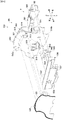
次に、画像表示装置5の右方に設けられた一般入賞球装置24及びその周辺の構成と、入賞球装置ユニット500の構成について説明する。図3は、遊技盤の一部の構成を示した分解斜視図である。   Next, the configuration of the general winning ball device 24 provided on the right side of the image display device 5 and its surroundings, and the configuration of the winning ball device unit 500 will be described. FIG. 3 is an exploded perspective view showing a partial configuration of the game board.

図3に示すように、透明な材料からなる遊技盤面2aの略中央には、画像表示装置5及び演出ユニット300(ともに図1に図示)を視認させるための開口2cが形成されている。この開口2cの縁に沿って該開口2cを取り囲むように、センター飾り枠51が遊技盤面2aに取り付けられている。センター飾り枠51は、遊技領域を流下する遊技球が画像表示装置5や演出ユニット300に接触しないように、遊技球の流れを規制し、打ち出された遊技球を左遊技領域と右遊技領域とに振り分けるための枠体である。このセンター飾り枠51には、通過ゲート41と一般入賞球装置24とが設けられている。センター飾り枠51、通過ゲート41、及び一般入賞球装置24は、アクリル樹脂、ポリカーボネート樹脂、メタクリル樹脂等の透明な合成樹脂材にて形成されている。また、遊技盤2は、遊技盤本体70に取り付けられる装飾体200、遊技球経路400、及び入賞球装置ユニット500を有している。入賞球装置ユニット500は、普通可変入賞球装置6Bと特別可変入賞球装置7とを備えている。なお、パチンコ遊技機1を構成する各部材は、特に言及がない限り、合成樹脂又は金属により形成されている。また、各部材に関する取り付けは、特に言及がない限り、ネジ、ビス等を用いた取り付けや、嵌合等の取り付け、溶接、溶着等、適宜の方法で行えばよい。   As shown in FIG. 3, an opening 2c for visually recognizing the image display device 5 and the rendering unit 300 (both shown in FIG. 1) is formed substantially at the center of the game board surface 2a made of a transparent material. A center decorative frame 51 is attached to the game board surface 2a so as to surround the opening 2c along the edge of the opening 2c. The center decorative frame 51 regulates the flow of the game ball so that the game ball flowing down the game area does not contact the image display device 5 or the rendering unit 300, and sets the launched game ball to the left game area and the right game area. It is a frame for sorting. The center decorative frame 51 is provided with a passage gate 41 and a general winning ball device 24. The center decorative frame 51, the passing gate 41, and the general winning ball device 24 are formed of a transparent synthetic resin material such as an acrylic resin, a polycarbonate resin, and a methacrylic resin. Further, the game board 2 has a decorative body 200 attached to the game board body 70, a game ball path 400, and a winning ball device unit 500. The winning ball device unit 500 includes a normal variable winning ball device 6B and a special variable winning ball device 7. Each member constituting the pachinko gaming machine 1 is formed of a synthetic resin or metal unless otherwise specified. The attachment of each member may be performed by an appropriate method such as attachment using screws, screws, or the like, attachment such as fitting, welding, welding, or the like, unless otherwise specified.

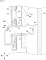
まず、一般入賞球装置24及びその周辺の構成について説明する。図4は、遊技盤に設けられた装飾体を示す図であり、(a)は分解斜視図、(b)は(a)中の矢視B−Bからみた正面図である。図5は、図1中の矢視V−Vで示したパチンコ遊技機1の断面図である。図6は、図5中の矢視VI−VIで示した断面図である。   First, the configuration of the general winning ball apparatus 24 and its surroundings will be described. 4A and 4B are diagrams illustrating a decorative body provided on the game board, wherein FIG. 4A is an exploded perspective view, and FIG. 4B is a front view as viewed from the arrow BB in FIG. FIG. 5 is a cross-sectional view of the pachinko gaming machine 1 indicated by an arrow VV in FIG. FIG. 6 is a sectional view taken along the line VI-VI in FIG.

一般入賞球装置24は、右遊技領域を流下する遊技球が進入可能な一般入賞口24bを有している。一般入賞口24bに進入した遊技球は後方に向けて流下する。遊技盤面2aには、後方に流下する遊技球を通すための開口である通過孔2dが形成されている。   The general prize ball device 24 has a general prize port 24b through which game balls flowing down the right game area can enter. The game ball that has entered the general winning opening 24b flows downward. On the game board surface 2a, there is formed a through hole 2d which is an opening for passing a game ball flowing backward.

装飾体200は、一般入賞口24bに進入し後方に移動する遊技球が進入する進入口200aを有している。装飾体200は、進入口200aを遊技盤面2aに形成された通過孔2dに一致させた状態で、遊技盤面2aに後方から取り付けられる。図4に示すように、装飾体200は、ベース体210と、3つのLED221〜223を搭載したLED基板220と、LED221〜223から発せられた光を取り込み導光しながら前方へと出射するレンズ体230と、装飾体200の最前面を構成するカバー体240とを備えている。またカバー体240の前面には、パチンコ遊技機1特有の装飾や模様が付されたシール250が貼付されている。   The decorative body 200 has an entrance 200a into which a game ball that enters the general winning opening 24b and moves rearward enters. The decorative body 200 is attached to the game board surface 2a from behind with the entrance 200a aligned with the passage hole 2d formed in the game board surface 2a. As shown in FIG. 4, the decoration body 200 includes a base body 210, an LED substrate 220 on which three LEDs 221 to 223 are mounted, and a lens that takes in light emitted from the LEDs 221 to 223 and emits the light forward while guiding the light. A body 230 and a cover 240 constituting the forefront of the decorative body 200 are provided. On the front surface of the cover 240, a sticker 250 with decorations and patterns unique to the pachinko gaming machine 1 is attached.

ベース体210は、例えば、非透光性の合成樹脂から形成されており、装飾体200を構成する種々の部材が取り付けられる。ベース体210の前面には、左下方向に延びた平行四辺形状の3つの反射面210a、210b、210cが形成されている。これらの反射面210a、210b、210cは、上下方向に沿って並列しており、レンズ体230から後方に向けて出射された光を反射して再度レンズ体230に入射させる。これにより、レンズ体230から前方へ出射される光の量を多くすることができる。また、ベース体210には、レンズ体230に形成された遊技球の流下経路となる筒状体231が挿通される挿通孔210dが形成されている。挿通孔210dは矩形状で、最も下方にある反射面210cの一部を打ち抜くように形成されている。   The base body 210 is formed of, for example, a non-light-transmitting synthetic resin, and various members constituting the decorative body 200 are attached thereto. On the front surface of the base body 210, three parallelogram-shaped reflecting surfaces 210a, 210b, 210c extending in the lower left direction are formed. These reflecting surfaces 210a, 210b, and 210c are arranged in parallel along the vertical direction, and reflect light emitted backward from the lens body 230 and make the light enter the lens body 230 again. Thus, the amount of light emitted forward from the lens body 230 can be increased. In addition, the base body 210 has an insertion hole 210d through which a cylindrical body 231 formed as a flow path of a game ball formed on the lens body 230 is inserted. The insertion hole 210d has a rectangular shape and is formed so as to punch a part of the lowermost reflection surface 210c.

LED基板220は、ベース体210の右側前面に取り付けられている。LED基板220には、上下方向に等間隔で並んだ3つのLED221〜223が取り付けられている。LED基板220がベース体210に取り付けられると、LED221は反射面210aの側方に、LED222は反射面210bの側方に、LED223は反射面210cの側方に位置する。3つのLED221〜223は、演出制御基板12(図2)からの制御データに基づいてランプ制御基板14(図2)により点灯/消灯駆動がされる。なお、LED221〜223は、後述するレンズ体230を照射するため、パチンコ遊技機1の電源が入れられている間(デモンストレーションの期間も含め)は常に点灯状態にある。   The LED substrate 220 is attached to the right front surface of the base body 210. The LED board 220 is provided with three LEDs 221 to 223 arranged at equal intervals in the vertical direction. When the LED substrate 220 is attached to the base body 210, the LED 221 is located on the side of the reflection surface 210a, the LED 222 is located on the side of the reflection surface 210b, and the LED 223 is located on the side of the reflection surface 210c. The three LEDs 221 to 223 are turned on / off by the lamp control board 14 (FIG. 2) based on control data from the effect control board 12 (FIG. 2). In addition, since the LEDs 221 to 223 illuminate a lens body 230 described later, the pachinko gaming machine 1 is always lit while the power of the pachinko gaming machine 1 is turned on (including the period of the demonstration).

レンズ体230は、アクリル樹脂、ポリカーボネート樹脂、メタクリル樹脂等の透明な合成樹脂材にて形成されている。レンズ体230は、ベース体210の前面に取り付けられる。レンズ体230は、左下に向けて延びる平行四辺形状の3つの導光部232〜234と、最も下方に位置する導光部234を突き抜けるように形成された筒状体231とを有している。導光部232〜234はそれぞれ、近傍に配置されたLED232〜234からの光が入射する光入射面232a、233a、234aを右側面に有している。また、各導光部232〜234の前面には、模様や文字等を表現する凹凸が形成されている。これにより、LED221〜223からの光が導光部232〜234に入射すると、入射した光は全反射を繰り返しながら導光され、前面に形成された凹凸によって全反射しなかった光は前方へと出射される。このように前方に出射される光には、導光部232〜234の前面に形成された模様や文字等が付加される。なお、各導光部232〜234の後方には、反射面210a、210b、210cが配置される。これにより、全反射せずに導光部232〜234の後方から出射された光は、反射面210a、210b、210cで反射され、再度導光部232〜234に入射させることができる。   The lens body 230 is formed of a transparent synthetic resin material such as an acrylic resin, a polycarbonate resin, and a methacrylic resin. The lens body 230 is attached to the front surface of the base body 210. The lens body 230 has three parallelogram-shaped light guides 232 to 234 extending to the lower left, and a cylindrical body 231 formed to penetrate the light guide 234 located at the lowest position. . Each of the light guides 232 to 234 has a light incident surface 232a, 233a, 234a on the right side on which light from the LED 232 to 234 arranged in the vicinity is incident. Further, on the front surface of each of the light guides 232 to 234, irregularities expressing patterns, characters, and the like are formed. Thus, when the light from the LEDs 221 to 223 enters the light guide units 232 to 234, the incident light is guided while repeating total reflection, and the light that has not been totally reflected by the unevenness formed on the front surface is directed forward. Is emitted. In this manner, the light emitted forward is added with patterns, characters, and the like formed on the front surfaces of the light guides 232 to 234. In addition, reflection surfaces 210a, 210b, and 210c are disposed behind the light guides 232 to 234. As a result, light emitted from behind the light guides 232 to 234 without being totally reflected is reflected by the reflection surfaces 210a, 210b, and 210c, and can be incident on the light guides 232 to 234 again.

カバー体240は、透明な合成樹脂材にて形成されている。カバー体240は、ベース体210に取り付けられ、ベース体210やLED基板220を覆う。一方、導光部232〜234は、カバー体240の凹部240aに位置しており、カバー体240に覆われることはない。なお、カバー体240の前面に貼付されたシール250により、パチンコ遊技機1に装飾を施すことができる。   The cover body 240 is formed of a transparent synthetic resin material. The cover 240 is attached to the base 210 and covers the base 210 and the LED board 220. On the other hand, the light guides 232 to 234 are located in the concave portions 240 a of the cover 240 and are not covered by the cover 240. The pachinko gaming machine 1 can be decorated with the seal 250 attached to the front surface of the cover body 240.

遊技球経路400は、筒状体231内部を後方に移動した遊技球が進入する進入口400a(図3)を有している。遊技球経路400の内部には、進入した遊技球が流下する流路が形成されているとともに、一般入賞口24bから進入して流下する遊技球を検出する一般入賞球スイッチ24a(図2)が設けられている。   The game ball path 400 has an entrance 400a (FIG. 3) into which game balls that have moved rearward inside the cylindrical body 231 enter. Inside the game ball path 400, a flow path through which the entered game ball flows down is formed, and a general winning ball switch 24a (FIG. 2) for detecting a game ball entering and flowing down from the general winning opening 24b. Is provided.

続いて、一般入賞口24bに進入した遊技球の流れについて説明する。図5、図6に示すように、ガラス窓50aと遊技盤面2aとの間には、遊技球が移動可能な隙間が形成されている。一般入賞球装置24は、この隙間に突出する一般入賞口24bを有している。図5に示すように、ガラス窓50aと遊技盤面2aとの間を流下する遊技球P1が、一般入賞口24bから進入すると(遊技球P2)、後方へと流下方向を変える。そして遊技球は、遊技盤面2に形成された通過孔2dを通り、筒状体231の進入口200aに進入する(遊技球P3)。さらに、遊技球P3は、筒状体231内を後方へと移動し、遊技球経路400の進入口400aに進入する。遊技球経路400は、進入口400aの直後からおおよそ90度下方へと流路を変更させた屈曲部400bを有している。これにより、遊技球P4は、遊技球経路400に進入後直ぐに、後方から下方へと流下方向を変更する。そして、遊技球P4は、そのまま下方へと移動し(遊技球P5)、やがて一般入賞球スイッチ24a(図2)により検出される。このようにして、一般入賞口24bから進入した遊技球は、遊技盤面2aの通過孔2dを通り、遊技盤面2aの後方へと移動していく。   Next, the flow of the game ball that has entered the general winning opening 24b will be described. As shown in FIGS. 5 and 6, a gap is formed between the glass window 50a and the game board surface 2a so that the game balls can move. The general winning prize ball device 24 has a general winning opening 24b protruding into this gap. As shown in FIG. 5, when the game ball P1 flowing between the glass window 50a and the game board surface 2a enters from the general winning opening 24b (game ball P2), the flowing direction changes backward. Then, the game ball passes through the passage hole 2d formed in the game board surface 2 and enters the entrance 200a of the tubular body 231 (game ball P3). Further, the game ball P3 moves backward in the cylindrical body 231 and enters the entrance 400a of the game ball path 400. The game ball path 400 has a bent portion 400b whose flow path is changed approximately 90 degrees downward immediately after the entrance 400a. As a result, immediately after entering the game ball path 400, the game ball P4 changes the flowing direction from the rear downward. Then, the game ball P4 moves downward as it is (game ball P5), and is detected by the general winning ball switch 24a (FIG. 2). In this way, the game ball that has entered from the general winning opening 24b passes through the passage hole 2d of the game board surface 2a and moves to the rear of the game board surface 2a.

次に、装飾体200に設けられたLED221〜223のうち、もっとも下に位置するLED223から出射された光の進み方について説明する。図6の部分拡大図に示すように、LED223から出射された光は、近傍の光入射面233aに入射する。光入射面233aに入射した光は、導光部234内部を左方へと進み(矢印L1)、あるいはレンズ体230の表面で全反射しながら左方へと進む(矢印L2)。やがて、導光された光は、筒状体231の空洞部231aに出射され広がりながら左方へと進み(L3)、再びレンズ体230の内部に入射する。再びレンズ体230の内部に進入した光は、導光部234の内部を左方へと進んだり(L4)、導光部234の表面で全反射しながら左方へと進んだり(L5)、導光部234の前面に形成された凹凸234aによって全反射されずに前方へと出射されたり(L6)、導光部234の表面で全反射されずに後方へ出射された後に反射面210cに反射されて再び導光部234の内部に進入する(L7)、といった光路を進む。このように、導光部234の内部で導光されながら前方へと光が出射されることにより、導光部234の全面から光を出射することができるとともに、出射された光に凹凸234aによる模様や文字等を付加することができる。   Next, how the light emitted from the LED 223 located at the lowest position among the LEDs 221 to 223 provided on the decorative body 200 will be described. As shown in the partially enlarged view of FIG. 6, the light emitted from the LED 223 enters the nearby light incident surface 233a. The light that has entered the light incident surface 233a travels to the left inside the light guide 234 (arrow L1), or travels to the left while being totally reflected on the surface of the lens body 230 (arrow L2). Eventually, the guided light is emitted to the hollow portion 231a of the cylindrical body 231 and proceeds to the left while expanding (L3), and again enters the inside of the lens body 230. The light that has entered the inside of the lens body 230 again travels to the left inside the light guide 234 (L4), or travels to the left while being totally reflected by the surface of the light guide 234 (L5). The light is emitted forward without being totally reflected by the unevenness 234a formed on the front surface of the light guide portion 234 (L6), or is emitted backward without being totally reflected on the surface of the light guide portion 234, and then is reflected on the reflection surface 210c. The reflected light enters the light guide 234 again (L7). In this way, by emitting light forward while being guided inside the light guide 234, light can be emitted from the entire surface of the light guide 234, and the emitted light is formed by the unevenness 234a. Patterns, characters, and the like can be added.

このように、LED223から出射され光入射面233aから入射した光は、導光部234から前方に出射させる前に筒状体231の空洞部231aを通過する。これにより、遊技球の流下路を構成する空洞部231aに光が照射される。なお、LED223は、パチンコ遊技機1の電源が投入されている間(デモンストレーションの期間も含め)は常に点灯状態にある。そのため、空洞部231aも、パチンコ遊技機1の電源が投入されている間は常に明るく照射されている。この筒状体231の空洞部231aは、一般入賞口24bに進入した遊技球の流路を構成している。そのため、筒状体232の空洞部231aを通過する遊技球には、LED223から出射された光が当たり反射される。これにより、遊技球は光輝いたように視認される。以下、一般入賞口24bに進入した遊技球に光を反射させ光輝いたように見せる演出を「入賞演出」と記載する。   As described above, the light emitted from the LED 223 and incident from the light incident surface 233a passes through the hollow portion 231a of the tubular body 231 before being emitted forward from the light guide 234. As a result, light is emitted to the hollow portion 231a constituting the downflow path of the game ball. Note that the LED 223 is always on while the pachinko gaming machine 1 is powered on (including the period of the demonstration). Therefore, the hollow portion 231a is always illuminated brightly while the power of the pachinko gaming machine 1 is turned on. The hollow portion 231a of the cylindrical body 231 forms a flow path of a game ball that has entered the general winning opening 24b. Therefore, the light emitted from the LED 223 hits the game ball passing through the hollow portion 231a of the cylindrical body 232 and is reflected. Thereby, the game ball is visually recognized as shining. Hereinafter, an effect that reflects light to a game ball that has entered the general winning opening 24b to make it look brilliant will be referred to as “winning effect”.

なお、遊技球に光が照射される範囲は、概ね遊技球P3から遊技球P4の範囲(図5、図6中の実線の矢印Yで示す範囲)に設定される。この矢印Yで示す流路の範囲は、第1所定領域と記載することがあるものとし、遊技球の後方へ移動する区間(筒状体231の内部)と、遊技球経路400に進入後に下方へ移動する区間(屈曲部400b)とを含んでいる。図5、図6に示すように、遊技球P3には、照射範囲P3´において照射された光を反射する。この照射範囲P3´は、遊技球P3の後部右側に位置している。また、遊技球P4には、照射範囲P4´において照射された光を反射する。この照射範囲P4´は、遊技球P4の前部上側に位置している。このように、遊技球に光が照射され該光を反射する矢印Yで示す第1所定領域の範囲では、遊技球の移動に伴って遊技球における照射範囲の大きさと位置が刻々と変化する。これにより、遊技球が反射する光の態様を変化させることが可能となる。一方、図5、図6中の破線の矢印で示す範囲にある遊技球には、光が照射されず、遊技球はLED223からの光を反射しない。これにより、LED223を常時発光させていたとしても、一般入賞口24bに進入し流下する遊技球が突然光り輝く入賞演出を実行できる。   The range in which the game balls are irradiated with light is set substantially in the range from the game balls P3 to the game balls P4 (the range indicated by the solid line arrow Y in FIGS. 5 and 6). The range of the flow path indicated by the arrow Y is sometimes referred to as a first predetermined area, and is defined as a section moving inside the game ball (inside the tubular body 231) and a lower area after entering the game ball path 400. (Bend 400b). As shown in FIGS. 5 and 6, the light applied to the game ball P3 in the irradiation range P3 'is reflected. This irradiation range P3 'is located on the rear right side of the game ball P3. The light applied to the game ball P4 in the irradiation range P4 'is reflected. This irradiation range P4 'is located on the front upper side of the game ball P4. As described above, in the range of the first predetermined region indicated by the arrow Y that irradiates the game ball with light and reflects the light, the size and the position of the irradiation range on the game ball change every moment as the game ball moves. Thereby, it becomes possible to change the mode of the light reflected by the game ball. On the other hand, the game balls in the range indicated by the broken arrows in FIGS. 5 and 6 are not irradiated with light, and the game balls do not reflect the light from the LED 223. As a result, even if the LED 223 is constantly lit, it is possible to execute a prize-winning effect in which a game ball entering the general winning opening 24b and flowing down suddenly shines.

また、第1所定領域を流下する遊技球には光が照射されるが、その際、遊技球は、流下路である空洞部231aへの光と導光部234に入射する光とを遮る。そのため、遊技球が第1所定領域を通る際、空洞部231a及び導光部234は暗くなる。なお、空洞部231aと導光部234とを照らすLED223は、パチンコ遊技機1の電源が投入されている間、常に発光されている。これにより、空洞部231a及び導光部234に光が照射されていることに慣れている遊技者は、空洞部231a及び導光部234が暗くなったことに気づきやすい。これと同時に、あるいはこの後すぐに、遊技球が光輝く入賞演出を実行することができる。これにより、周囲を暗くしたなかで、遊技球を光輝かせることができるため、演出効果を向上させることができる。   In addition, the game ball that flows down the first predetermined area is irradiated with light. At this time, the game ball blocks light to the hollow portion 231a that is a flow-down path and light that enters the light guide portion 234. Therefore, when the game ball passes through the first predetermined area, the hollow part 231a and the light guide part 234 become dark. The LED 223 that illuminates the cavity 231a and the light guide 234 emits light at all times while the pachinko gaming machine 1 is powered on. Accordingly, a player who is accustomed to irradiating the cavity 231a and the light guide 234 with light is likely to notice that the cavity 231a and the light guide 234 have become dark. At the same time or shortly thereafter, a winning effect in which the game ball shines can be executed. As a result, the game balls can be made to shine while the surroundings are darkened, so that the effect can be improved.

なお、上記では、LED基板220に搭載されたLED221〜LED223のうち、最も下方に位置するLED223から出射された光の進み方について説明した。ここでは、他のLED221、222から出射された光の進み方については説明を省略するが、導光部232、233に左方へと導光されながら前方へ出射されるより単純な光の進み方をする。   In the above, the way of traveling of the light emitted from the LED 223 located at the lowest position among the LEDs 221 to 223 mounted on the LED substrate 220 has been described. Here, the description of how the light emitted from the other LEDs 221 and 222 travels is omitted, but a simpler light travel that is emitted forward while being guided leftward by the light guide units 232 and 233 is described. To

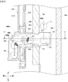
次に、入賞球装置ユニット500の構成について説明する。図7は、入賞球装置ユニットの斜視図であり、(a)は前方からみた斜視図、(b)は後方からみた見た斜視図である。図8は、入賞球装置ユニットを前方からみた分解斜視図であり、図9は、入賞球装置ユニットを後方からみた分解斜視図である。図10は、特別可変入賞球装置の構成要素である第2可動装置の分解斜視図である。   Next, the configuration of the winning ball device unit 500 will be described. 7A and 7B are perspective views of the winning ball device unit. FIG. 7A is a perspective view as viewed from the front, and FIG. 7B is a perspective view as viewed from the rear. FIG. 8 is an exploded perspective view of the winning ball device unit viewed from the front, and FIG. 9 is an exploded perspective view of the winning ball device unit viewed from the rear. FIG. 10 is an exploded perspective view of a second movable device that is a component of the special variable winning ball device.

入賞球装置ユニット500は、普通可変入賞球装置6B及び特別可変入賞球装置7の2つの入賞球装置を備えている。普通可変入賞球装置6B及び特別可変入賞球装置7はベース板510を共有しており、ベース板510の上部であるベース板上部510aは、普通可変入賞球装置6Bのベース板として機能する。また、ベース板下部510bは、特別可変入賞球装置7のベース板として機能する。   The winning ball device unit 500 includes two winning ball devices: a normal variable winning ball device 6B and a special variable winning ball device 7. The normal variable prize ball device 6B and the special variable prize ball device 7 share a base plate 510, and a base plate upper portion 510a, which is an upper portion of the base plate 510, functions as a base plate of the normal variable prize ball device 6B. Further, the base plate lower part 510b functions as a base plate of the special variable winning ball device 7.

普通可変入賞球装置6Bは、ベース板上部510aと、ベース板上部510aに後方から取り付けられる第1可動装置550と、ベース板上部510aに前方から取り付けられるカバー体520と、を備えている。   The normal variable winning prize ball device 6B includes a base plate upper portion 510a, a first movable device 550 attached to the base plate upper portion 510a from behind, and a cover body 520 attached to the base plate upper portion 510a from the front.

ベース板上部510aは、普通可変入賞球装置6Bの各種部品を保持した状態で、遊技盤面2a(図3)に取り付けられる。ベース板上部510aには、可動板551が挿通される可動板挿通孔512(図8)が形成されている。   The upper base plate 510a is attached to the game board surface 2a (FIG. 3) while holding various components of the normally variable winning prize ball device 6B. A movable plate insertion hole 512 (FIG. 8) through which the movable plate 551 is inserted is formed in the base plate upper portion 510a.

第1可動装置550は、図8、9に示すように、前後方向にスライド可能な可動板551と、可動板551を前後方向に移動させるソレノイド81とを有している。ソレノイド81が可動板551を移動させるための構成については、後述する第2可動装置560における構成と同様である。ソレノイド81がオフ状態にあるとき、図8に示すように、可動板551は、ベース板上部510aから突出した状態となる。一方、ソレノイド82がオフ状態からオン状態へと移行すると、可動板551は、後方へと移動しベース板上部510aから突出することがない位置まで後退する。   As shown in FIGS. 8 and 9, the first movable device 550 includes a movable plate 551 slidable in the front-rear direction, and a solenoid 81 for moving the movable plate 551 in the front-rear direction. The configuration for the solenoid 81 to move the movable plate 551 is the same as the configuration of the second movable device 560 described later. When the solenoid 81 is in the off state, as shown in FIG. 8, the movable plate 551 is in a state of protruding from the upper portion 510a of the base plate. On the other hand, when the solenoid 82 shifts from the off state to the on state, the movable plate 551 moves rearward and retreats to a position where it does not protrude from the upper portion 510a of the base plate.

カバー体520は、図9に示すように、パチンコ遊技機1特有の装飾が施された装飾板521と、装飾板521の後面に形成された傾斜面522及び傾斜面523と、傾斜面522と傾斜面523との間に設けられた凹部である進入口524とを有している。傾斜面522及び傾斜面523は、右方に向かうにつれ下向きの傾斜を有している。可動板551がベース板上部510aから突出した状態になると、進入口524の上方は閉じられ、普通可変入賞球装置6Bは閉鎖状態となる。一方、可動板551がベース板上部510aから突出しない状態になると、進入口524の上方が開放し、普通可変入賞球装置6Bは開放状態となる。普通可変入賞球装置6Bが開放状態となると、傾斜面522を右下に流下する遊技球は、進入口524に進入可能となる。普通可変入賞球装置6Bに進入した遊技球は、ベース板510に形成された通過孔514(図8)を通過して第1可動装置550に進入し、第1可動装置550に設けられた第2始動口スイッチ22B(図2)に検出される。   As shown in FIG. 9, the cover body 520 includes a decorative plate 521 on which decoration specific to the pachinko gaming machine 1 is provided, an inclined surface 522 and an inclined surface 523 formed on a rear surface of the decorative plate 521, and an inclined surface 522. It has an entrance 524 which is a concave portion provided between the inclined surface 523. The inclined surface 522 and the inclined surface 523 have a downward inclination toward the right. When the movable plate 551 projects from the upper portion 510a of the base plate, the upper portion of the entrance 524 is closed, and the normally variable winning prize ball device 6B is closed. On the other hand, when the movable plate 551 does not protrude from the upper portion 510a of the base plate, the upper part of the entrance 524 is opened, and the normally variable winning prize ball device 6B is opened. When the normally variable winning prize ball device 6B is in an open state, game balls flowing down the inclined surface 522 to the lower right can enter the entrance 524. The game ball that has entered the normally variable winning prize ball device 6B passes through the through hole 514 (FIG. 8) formed in the base plate 510, enters the first movable device 550, and is provided on the first movable device 550. It is detected by the 2 start port switch 22B (FIG. 2).

普通可変入賞球装置6Bの下方に位置する特別可変入賞球装置7は、ベース板下部510bと、ベース板下部510bに後方から取り付けられる第2可動装置560と、ベース板下部510bに前方から取り付けられるカバー体530と、カバー体530の後面に取り付けられるLED基板540とを備えている。   The special variable winning ball device 7 located below the normal variable winning ball device 6B is attached to the base plate lower portion 510b, the second movable device 560 attached to the base plate lower portion 510b from behind, and attached to the base plate lower portion 510b from the front. A cover body 530 and an LED board 540 attached to the rear surface of the cover body 530 are provided.

ベース板下部510bは、特別可変入賞球装置7の各種部品を保持した状態で、遊技盤面2a(図3)に取り付けられる。ベース板下部510bには、可動板561が挿通される可動板挿通孔513と、特別可変入賞球装置7に入賞した遊技球が通過する通過孔515と、普通可変入賞球装置6Bに進入せずに流下する遊技球の飛び出しを防止する飛び出し防止部511と、カバー体530に形成された規制片537とともに流下する遊技球の勢いを抑制する規制片516とが形成されている。   The base plate lower part 510b is attached to the game board surface 2a (FIG. 3) while holding various parts of the special variable winning ball device 7. In the base plate lower part 510b, the movable plate insertion hole 513 through which the movable plate 561 is inserted, the through hole 515 through which the game ball that has won the special variable winning ball device 7 passes, and the normal variable winning ball device 6B does not enter. And a restriction piece 516 for suppressing the momentum of the game ball flowing down together with the restriction piece 537 formed on the cover body 530.

第2可動装置560は、図10に示すように、種々の部品が保持体562に取り付けられて構成されている。   As shown in FIG. 10, the second movable device 560 is configured by attaching various components to a holding body 562.

ソレノイド82は、ソレノイド本体82aとプランジャ―82bとを備えている。ソレノイド82に電流が流れていない場合には、図10に示すようにプランジャ82bはソレノイド本体82aから突出した状態にある。この状態からソレノイド82に電流を流すと、プランジャ82bは、ソレノイド本体82aに引き寄せられてソレノイド本体82aからの突出量が小さくなる。   The solenoid 82 includes a solenoid main body 82a and a plunger 82b. When no current is flowing through the solenoid 82, the plunger 82b is in a state of protruding from the solenoid body 82a as shown in FIG. When a current is applied to the solenoid 82 from this state, the plunger 82b is drawn to the solenoid main body 82a, and the amount of protrusion from the solenoid main body 82a is reduced.

連結片563は、略L字型状をなし、プランジャ82bの先端に連結される連結部563aと、保持体562に左右方向に沿って形成されたスリット562aに挿入される突起563bと、回動片564の突起564aが挿通される挿通孔部563cとを有している。連結片563は、連結されたプランジャ82bの動きに連動し、スリット562aが延びる左右方向に沿って移動する。   The connecting piece 563 has a substantially L-shape, and has a connecting portion 563a connected to the tip of the plunger 82b, a projection 563b inserted into a slit 562a formed in the holder 562 along the left-right direction, and a rotation. And an insertion hole 563c through which the projection 564a of the piece 564 is inserted. The connecting piece 563 moves in the left-right direction in which the slit 562a extends, in conjunction with the movement of the connected plunger 82b.

回動片564は、挿通孔部563cに挿通される突起564aと、保持体562に形成されたスリット562eに挿通される移動突起564bと、可動板561の突起561aが挿通される挿通孔部564cと、保持体562に形成された突起である回転軸部562fが挿通され回動片564を回動可能に保持する挿通孔部564dと、を有している。回動片564の突起564aは、連結片563の左右方向の移動に伴い挿通孔部563cの孔壁に押圧される。これにより、回動片564は、回転軸部562fを中心に回動する。   The rotating piece 564 includes a projection 564a inserted into the insertion hole 563c, a moving projection 564b inserted into a slit 562e formed in the holder 562, and an insertion hole 564c through which the projection 561a of the movable plate 561 is inserted. And a through-hole 564d through which a rotating shaft 562f, which is a projection formed on the holding body 562, is inserted to hold the rotating piece 564 in a rotatable manner. The protrusion 564a of the rotating piece 564 is pressed against the hole wall of the insertion hole 563c as the connecting piece 563 moves in the left-right direction. As a result, the rotating piece 564 rotates around the rotating shaft 562f.

可動板561は、略矩形状のプレートである可動板本体561cと、可動板本体561cの下面に形成された円柱状の突起561aと、直方体状の対の規制片561b、561dとを有している。突起561aは、保持体562に形成された長孔562bと、回動片564に形成された挿通孔部564cとを連通する。長孔562bの長軸は、前後方向に設定されている。また、規制片561bは前後方向に沿って形成された溝部562cに、規制片561dは前後方向に沿って形成された溝部562dに挿入される。このような構成により、回動軸部562fを中心に回動すると、突起561aは挿通孔部564cの孔壁に押圧される。これにより、可動板561は、長孔562b及び溝部562cの延びる方向(前後方向)に沿って移動する。   The movable plate 561 includes a movable plate body 561c that is a substantially rectangular plate, a columnar protrusion 561a formed on the lower surface of the movable plate body 561c, and a pair of rectangular parallelepiped regulating pieces 561b and 561d. I have. The protrusion 561a communicates the long hole 562b formed in the holding body 562 with the insertion hole 564c formed in the rotating piece 564. The long axis of the long hole 562b is set in the front-back direction. The restriction piece 561b is inserted into a groove 562c formed along the front-rear direction, and the restriction piece 561d is inserted into a groove 562d formed along the front-rear direction. With this configuration, when the rotation is made around the rotation shaft 562f, the protrusion 561a is pressed against the hole wall of the insertion hole 564c. As a result, the movable plate 561 moves along the direction in which the elongated hole 562b and the groove 562c extend (front-back direction).

このように、ソレノイド82の電流がオン/オフを繰り返すことによりプランジャ82bは左右方向に移動する。このプランジャ82bの移動に伴い、可動板561は、連結片563及び回動片564を介して前後方向に移動する。   In this way, the plunger 82b moves in the left-right direction by repeatedly turning on / off the current of the solenoid 82. With the movement of the plunger 82b, the movable plate 561 moves in the front-rear direction via the connecting piece 563 and the rotating piece 564.

カウントスイッチ23は、特別可変入賞球装置7に入賞して案内されてきた遊技球の流路560aに配置される。カウントスイッチ23は、特別可変入賞球装置7に入賞した遊技球を検出する。   The count switch 23 is arranged in the flow path 560a of the game ball which has been guided to the special variable winning ball device 7 by winning. The count switch 23 detects a game ball that has won the special variable winning ball device 7.

カバー体530は、例えば、アクリル樹脂、ポリカーボネート樹脂、メタクリル樹脂等の透明な合成樹脂材にて形成されている。カバー体530は、図9に示すように、パチンコ遊技機1特有の装飾が施された装飾板531と、装飾板531の後面から突出した傾斜面532と、傾斜面532の左方に設けられた凹部である進入口533と、ベース板下部510bに形成された規制片516とともに流下する遊技球の勢いを抑制する規制片537とを有している。   The cover body 530 is formed of, for example, a transparent synthetic resin material such as an acrylic resin, a polycarbonate resin, and a methacrylic resin. As shown in FIG. 9, the cover body 530 is provided on a decorative plate 531 on which decoration unique to the pachinko gaming machine 1 is provided, an inclined surface 532 protruding from the rear surface of the decorative plate 531, and a left side of the inclined surface 532. It has an entrance 533 which is a concave portion, and a regulation piece 537 for suppressing the momentum of the game ball flowing down together with the regulation piece 516 formed in the base plate lower part 510b.

装飾板531の裏面には、複数の凹凸が形成されており、後述するように後方からの光に模様を付すことができる。また、装飾板531の前面には、星形状の星形図形536が描かれている。この星形図形536にも後方から光を照射することにより、星が光っているかのうように視認させることができる。傾斜面532は、左方に向かうにつれ下向きの傾斜を有しており、普通可変入賞球装置6B側の傾斜面522、523とは傾斜方向が異なっている。そして、可動板561がベース板下部510bから突出した状態になると、進入口533の上方は閉じられ、特別可変入賞球装置7は閉鎖状態となる。一方、可動板561がベース板下部510bから突出しない状態になると、進入口533の上方が開放され、特別可変入賞球装置7は開放状態となる。特別可変入賞球装置7が開放状態となると、傾斜面532を左下に流下する遊技球は、進入口533に進入可能となる。   A plurality of irregularities are formed on the back surface of the decorative plate 531 so that light from behind can be patterned as described later. A star-shaped star-shaped figure 536 is drawn on the front surface of the decorative plate 531. By irradiating the star-shaped figure 536 with light from behind, the star can be visually recognized as if the star is shining. The inclined surface 532 has a downward inclination toward the left, and has a different inclination direction from the inclined surfaces 522 and 523 on the side of the normally variable winning prize ball device 6B. When the movable plate 561 projects from the base plate lower portion 510b, the upper part of the entrance 533 is closed, and the special variable winning ball device 7 is in a closed state. On the other hand, when the movable plate 561 does not protrude from the base plate lower portion 510b, the upper part of the entrance 533 is opened, and the special variable winning ball device 7 is opened. When the special variable winning ball device 7 is in an open state, a game ball flowing down the inclined surface 532 to the lower left can enter the entrance 533.

また、進入口533の最下部には、1個の遊技球が落下可能な窪みである案内部533aが形成されている。案内部533aは、後方に向かうにつれ下方に傾斜している。また、案内部533aを補強するともに、進入した遊技球をスムーズに後方へと移動させるために、装飾板531と案内部533aとの隅角部に、リブ534が形成されている。リブ534は、後方に向けて緩やかに下降した緩斜面を有する第1リブ部534aと、後方に向けて大きく下降した急斜面を有する第2リブ部534bとから構成されている。進入口533が、このような案内部533aを有することで、進入口533に進入して案内部533aに落下した遊技球は、後方へと移動し、ベース板下部510bに形成された通過孔515を通り、第2可動装置560にの流路560a(図10)に進入する。そして、遊技球は、第2可動装置560に設けられたカウントスイッチ23(図10)によって検出される。   A guide 533a, which is a depression into which one game ball can drop, is formed at the lowermost portion of the entrance 533. The guide portion 533a is inclined downward toward the rear. Further, a rib 534 is formed at a corner of the decorative plate 531 and the guide portion 533a in order to reinforce the guide portion 533a and smoothly move the entered game ball backward. The rib 534 is composed of a first rib portion 534a having a gentle slope that gradually descends rearward, and a second rib portion 534b having a steep slope that largely descends rearward. Since the entrance 533 has such a guide portion 533a, the game ball that has entered the entrance 533 and dropped on the guide portion 533a moves rearward and passes through the passage hole 515 formed in the base plate lower portion 510b. And enters the flow path 560a (FIG. 10) to the second movable device 560. The game ball is detected by the count switch 23 (FIG. 10) provided on the second movable device 560.

また、カバー体530の進入口533の下方には、LED基板540の外形に合わせた基板収容部535が形成されている。LED基板540は、カバー体530にねじ止めされ、基板収容部535に収容される。   Further, below the entrance 533 of the cover body 530, a board housing portion 535 that matches the outer shape of the LED board 540 is formed. The LED board 540 is screwed to the cover body 530 and housed in the board housing section 535.

LED基板540は、図8に示すように、左右方向に並んだ3つのLED541〜543を搭載している。3つのLED541〜543は、演出制御基板12(図2)からの制御データに基づいてランプ制御基板14(図2)により点灯/消灯駆動がされる。3つのLED541〜543が点灯すると、出射された光は装飾板531から外部へされる。装飾板531には装飾が施されているため、出射される光には装飾による模様等が付加される。   As shown in FIG. 8, the LED substrate 540 has three LEDs 541 to 543 arranged in the left-right direction. The three LEDs 541 to 543 are turned on / off by the lamp control board 14 (FIG. 2) based on control data from the effect control board 12 (FIG. 2). When the three LEDs 541 to 543 are turned on, the emitted light is emitted from the decorative plate 531 to the outside. Since the decoration plate 531 is decorated, a pattern or the like by the decoration is added to the emitted light.

次に、入賞球装置ユニット500を流下する遊技球の動きについて説明する。図11は、遊技球装置ユニットを前方から見た斜視図であり、(a)は各入賞球装置が閉鎖状態にある場合、(b)は各入賞球装置が開放状態にある場合である。なお、図11においては、遊技球の動きが理解できるように、カバー体520の一部の図示を省略している。右遊技領域に打ち出され一般入賞球装置24(図1)に入賞しなかった遊技球は、入賞球装置ユニット500の近傍まで流下する。そのうち一部の遊技球は、入賞球装置ユニット500に到達する。なお、遊技領域に打ち出された遊技球は、それぞれが様々な動きをし、同様に動く遊技球はほとんどない。そのため、以下の説明では、遊技球の動きの一例を示すものとする。   Next, the movement of the game ball flowing down the winning ball device unit 500 will be described. FIG. 11 is a perspective view of the gaming ball device unit as viewed from the front. FIG. 11A shows a case where each winning ball device is in a closed state, and FIG. 11B shows a case where each winning ball device is in an open state. In FIG. 11, a part of the cover body 520 is not shown so that the movement of the game ball can be understood. The game ball that has been launched into the right game area and has not won the general winning ball device 24 (FIG. 1) flows down to the vicinity of the winning ball device unit 500. Some of the game balls reach the winning ball device unit 500. The game balls launched into the game area make various movements, and there are almost no game balls moving in the same manner. Therefore, in the following description, an example of the movement of the game ball will be described.

まず、入賞球装置ユニット500の各入賞球装置が閉鎖状態にある場合について説明する。図11(a)に示すように、普通可変入賞球装置6Bの傾斜面522に到達した遊技球P1は、傾斜面522を右下に向けて流下する。普通可変入賞球装置6Bは、可動板551が進入口524を塞いだ閉鎖状態にある。そのため、遊技球は可動板551、続いて傾斜面523の上を順に右下に転がる(遊技球P2)。やがて、遊技球は、傾斜面523から下方へと落下し、飛び出し防止部511に衝突する(遊技球P3)。このようにして、普通可変入賞球装置6Bを流下した遊技球は、特別可変入賞球装置7へと移動する。   First, the case where each winning ball device of the winning ball device unit 500 is in the closed state will be described. As shown in FIG. 11A, the game ball P1 that has reached the inclined surface 522 of the normally variable winning prize ball device 6B flows down the inclined surface 522 toward the lower right. The ordinary variable winning ball device 6B is in a closed state in which the movable plate 551 covers the entrance 524. Therefore, the game balls roll on the movable plate 551 and subsequently on the inclined surface 523 to the lower right in order (game balls P2). Eventually, the game ball falls downward from the inclined surface 523 and collides with the pop-out preventing portion 511 (game ball P3). In this way, the game ball that has flowed down the normally variable winning ball device 6B moves to the special variable winning ball device 7.

また、特別可変入賞球装置7は、可動板561が進入口533を塞いだ閉鎖状態にある。そのため、遊技球は、傾斜面532、続いて可動板561の上を順に左下に転がり(遊技球P4)、やがて特別可変入賞球装置7から転がり落ちる(遊技球P5)。なお、可動板561上の遊技球の流路には、カバー体530に形成された規制片537とベース板510に形成された規制片516が交互に突出している。これにより、可動板561の上を転がる遊技球は蛇行しながら流下するため、流下速度は遅くなる。これにより、可動板561上を遊技球が転がる時間を長くすることができ、その間に開放状態になれば進入口533に進入可能となる。これにより、進入口533に入賞しやすくすることができる。   Further, the special variable winning ball device 7 is in a closed state in which the movable plate 561 blocks the entrance 533. Therefore, the game ball rolls downward on the inclined surface 532 and subsequently on the movable plate 561 (game ball P4), and eventually rolls off the special variable winning ball device 7 (game ball P5). Note that, in the flow path of the game ball on the movable plate 561, regulating pieces 537 formed on the cover body 530 and regulating pieces 516 formed on the base plate 510 alternately protrude. As a result, the game balls rolling on the movable plate 561 flow down while meandering, so that the flow-down speed decreases. As a result, the time that the game ball rolls on the movable plate 561 can be lengthened, and if the game ball is opened during that time, it is possible to enter the entrance 533. As a result, it is possible to easily win the entrance 533.

このように、普通可変入賞球装置6Bと特別可変入賞球装置7とは、上下方向に並んで配置されており、普通可変入賞球装置6Bが流下した後に、特別可変入賞球装置7を流下する。そして、普通可変入賞球装置6Bにおける遊技球の流下方向(右下方向)と、特別可変入賞球装置7における遊技球の流下方向(左下方向)とが異なるように構成されている。   As described above, the normal variable prize ball device 6B and the special variable prize ball device 7 are arranged side by side in the vertical direction, and flow down the special variable prize ball device 7 after the normal variable prize ball device 6B flows down. . The flowing direction (lower right direction) of the game ball in the normal variable winning ball device 6B is different from the flowing direction (lower left direction) of the game ball in the special variable winning ball device 7.

これに対し、入賞球装置ユニット500の各入賞球装置が共に開放状態にある場合、図11(b)に示すように、普通可変入賞球装置6Bの傾斜面522に到達した遊技球P6は、傾斜面522の上を右下に向けて流下した後、開放された進入口524に進入する(遊技球P7)。また、普通可変入賞球装置6Bを経ずに、直接特別可変入賞球装置7の傾斜面532に到達した遊技球P8は、傾斜面532の上を左下に流下した後、開放された進入口533に進入する(遊技球P9)。なお、遊技球が傾斜面532の上を勢いよく左下に向けて流下したとしても、交互に形成された規制片516及び規制片537によりその勢いは低減される。これにより、遊技球は、進入口533を飛び越えることなく確実に該進入口533に進入することができる。   On the other hand, when each of the winning ball devices of the winning ball device unit 500 is in the open state, as shown in FIG. 11B, the game ball P6 that has reached the inclined surface 522 of the normally variable winning ball device 6B is After flowing down on the inclined surface 522 toward the lower right, it enters the opened entrance 524 (game ball P7). Also, the game ball P8 that has reached the inclined surface 532 of the special variable winning ball device 7 directly without passing through the normal variable winning ball device 6B, flows down on the inclined surface 532 to the lower left, and then is opened to the entrance 533. (Game ball P9). In addition, even if the game ball vigorously flows down on the inclined surface 532 toward the lower left, the force is reduced by the regulating pieces 516 and 537 formed alternately. Thus, the game ball can surely enter the entrance 533 without jumping over the entrance 533.

次に、LED基板540に搭載されたLED541〜543から出射された光による演出態様について説明する。図12は、LED基板が取り付けられたカバー体を示す図であり、(a)はカバー体の正面図、(b)は(a)中の矢視B−Bで示す断面図である。なお、図12(a)中の破線でハッチングした領域は、装飾板531の後面から突出した部位であり、傾斜面532や案内部533a等を形成する部位を表している。なお、上述したようにカバー体530は透明な材料から構成されており、内部に容易に光が入射可能になっている。また、LED541〜543から出射される光は、様々な方向に進みカバー体530内に入射する。そのため、以下の説明では、光の進み方の一例を示すものとする。   Next, a description will be given of an effect mode by light emitted from the LEDs 541 to 543 mounted on the LED substrate 540. 12A and 12B are diagrams illustrating a cover body to which an LED substrate is attached, wherein FIG. 12A is a front view of the cover body, and FIG. 12B is a cross-sectional view taken along line BB in FIG. The area hatched by a broken line in FIG. 12A is a part protruding from the rear surface of the decorative plate 531 and represents a part that forms the inclined surface 532, the guide part 533a, and the like. Note that, as described above, the cover body 530 is made of a transparent material, and light can easily enter the inside. Light emitted from the LEDs 541 to 543 proceeds in various directions and enters the cover body 530. Therefore, in the following description, an example of how light travels will be described.

図12(a)、(b)に示すように、星形図形536は、正面視してリブ534に重なるようにカバー体530に設けられている。また、リブ534の下方には、LED541〜543が左右方向に並んで配置されている。LED541〜543から出射された光は、その一部は前方にあるカバー体530の凹凸544(図12(b))で拡散され、そのままカバー体530から前方へ出射される。これにより、図12(a)に示すように、正面視してカバー体530のLED541〜543が位置する箇所を中心にして拡散された光が前方へ出射される。また、LED541〜543から出射された光の一部は、上方の案内部533aに向けて進む。案内部533aに向かった光の一部は、リブ534に入射し、空中との境界面である全反射面534cで全反射する。全反射した光は、カバー体530の星形図形536が形成された領域から前方へと出射される。   As shown in FIGS. 12A and 12B, the star-shaped figure 536 is provided on the cover body 530 so as to overlap the rib 534 when viewed from the front. The LEDs 541 to 543 are arranged below the rib 534 in the left-right direction. A part of the light emitted from the LEDs 541 to 543 is diffused by the unevenness 544 (FIG. 12B) of the cover body 530 located at the front, and is emitted forward from the cover body 530 as it is. Thereby, as shown in FIG. 12A, the light diffused around the location where the LEDs 541 to 543 of the cover body 530 are located when viewed from the front is emitted forward. In addition, a part of the light emitted from the LEDs 541 to 543 advances toward the upper guide portion 533a. Part of the light traveling toward the guide portion 533a enters the rib 534, and is totally reflected by a total reflection surface 534c which is a boundary surface with the air. The totally reflected light is emitted forward from the area of the cover body 530 where the star-shaped figure 536 is formed.

なお、リブ534の全反射面534cの形成角度は、全反射される光がカバー体530から遊技者に向けて出射されるように調整される。具体的に調節される全反射面534cの形成角度とは、図12(b)に示す、水平Hに対する全反射面534cの角度θである。この角度θは、LED541〜543の取り付け位置との関係も考慮して適切に決定される。   The angle at which the total reflection surface 534c of the rib 534 is formed is adjusted so that the light that is totally reflected is emitted from the cover body 530 toward the player. The formation angle of the total reflection surface 534c specifically adjusted is the angle θ of the total reflection surface 534c with respect to the horizontal H shown in FIG. The angle θ is appropriately determined in consideration of the relationship with the mounting positions of the LEDs 541 to 543.

なお、LED541〜543から光が出射され、出射された光が全反射されて遊技者に届くまでの光路上には、例えば凹凸544のような光を拡散させる部位は存在せず、平坦化された表面しか存在していない。そのため、LED541〜543からの光が拡散されずに直接遊技者に視認されることになる。   In addition, on the optical path from when the light is emitted from the LEDs 541 to 543 and the emitted light is totally reflected and reaches the player, there is no portion such as the unevenness 544 that diffuses the light, and the light is flattened. There is only a surface. Therefore, the light from the LEDs 541 to 543 is directly recognized by the player without being diffused.

このように、LED541〜543からの光を拡散させることなく、遊技者に向けて全反射させる構成とすることにより、リブ534位置で輝く強い光を遊技者に視認させることができる。また、強く光り輝いている部位に、星形図形536を配置することにより、まるで星が輝いているかのような演出を実行することができる。   As described above, the light from the LEDs 541 to 543 is totally diffused toward the player without being diffused, so that the strong light shining at the position of the rib 534 can be visually recognized by the player. In addition, by arranging the star-shaped figure 536 in a strongly shining part, it is possible to execute an effect as if the star were shining.

また、LED541〜543から出射され、案内部533aに向かった光のうち、リブ534に入射しなかった光は、リブ534周囲の案内部533aや、ベース板510に形成された通過孔515(図8)を明るく照射する。この案内部533aや通過孔515は、特別可変入賞球装置7に入賞した遊技球の流路である。そのため、案内部533aや通過孔515を通過する遊技球によって、照射されていた光が遮られて暗くなる部分が形成される一方、遊技球に光が反射して光輝く部分も形成される。このように、通過する遊技球により、光の見え方を逐一変化させることができ、遊技者を魅了する演出を提供することができる。   Also, of the light emitted from the LEDs 541 to 543 and directed to the guide portion 533a, the light that has not entered the rib 534 is the guide portion 533a around the rib 534 and the passage hole 515 formed in the base plate 510 (see FIG. 8) Irradiate brightly. The guide portion 533a and the passage hole 515 are flow paths for game balls that have won the special variable winning ball device 7. Therefore, the game ball passing through the guide portion 533a and the passage hole 515 forms a portion where the irradiated light is blocked and darkened, and a portion where the light is reflected by the game ball and shines. In this way, the appearance of light can be changed one by one by the passing game ball, and an effect that can attract the player can be provided.

次に、遊技盤2の後方に設けられた調整用スイッチ600について説明する。図13は、調整用スイッチの正面図である。調整用スイッチ600は、「0」〜「F」までの計16個のチャンネルを切り替えるスイッチである。店員は、つまみ601を回動操作することで、これらチャンネルを切り替えることができる。各チャンネル「0」〜「F」に対しては、演出における音量および光量の大きさが段階分けされている。チャンネル「0」〜「F」に対応する音量の段階を第1音量段階と称し、チャンネル「0」〜「F」に対応する光量の段階を第1光量段階とも称する。たとえば、チャンネルが「0」であれば、最小の音量に設定される第1音量段階と最小の光量に設定される第1光量段階とに設定される。チャンネルが「F」であれば、最大の音量に設定される第1音量段階と最大の光量に設定される第1光量段階とに設定される。   Next, the adjustment switch 600 provided behind the game board 2 will be described. FIG. 13 is a front view of the adjustment switch. The adjustment switch 600 is a switch for switching a total of 16 channels from “0” to “F”. The clerk can switch these channels by rotating the knob 601. For each of the channels “0” to “F”, the volume and the amount of light in the effect are divided into stages. The level of the volume corresponding to channels "0" to "F" is referred to as a first volume level, and the level of the light quantity corresponding to channels "0" to "F" is also referred to as a first level of light. For example, if the channel is “0”, the first volume level is set to the minimum volume and the first light level is set to the minimum volume. If the channel is “F”, the first volume level is set to the maximum volume and the first light level is set to the maximum volume.

なお、調整用スイッチ600の操作に基づき店員が設定する音量および光量の大きさに対する段階を第1音量段階および第1光量段階と称するのに対して、遊技者による操作によって、遊技者が設定可能な音量および光量の大きさに対する段階を第2音量段階および第2光量段階とも称する。   The steps for the volume and the amount of light set by the store clerk based on the operation of the adjustment switch 600 are referred to as a first volume step and a first light level, but can be set by the player by an operation by the player. A stage corresponding to a large volume and a large amount of light is also referred to as a second volume stage and a second light stage.

演出制御用CPU120は、店員が調整用スイッチ600を操作することにより、LED221〜223、遊技効果ランプ9、及びLED541〜543の光量を調整用スイッチ600のチャンネルに応じた第1光量段階に調整し、スピーカ8L、8Rの音量を調整用スイッチ600のチャンネルに応じた第1音量段階に調整する。また、演出制御用CPU120は、客待ちの状態において遊技者がプッシュボタン31Bなどを操作することにより、調整用スイッチ600のチャンネルに応じて予め定められた光量範囲および音量範囲内のうちのいずれかに調整して、LED221〜223、遊技効果ランプ9、及びLED541〜543の光量、スピーカ8L、8Rの音量を制御する。   The effect control CPU 120 adjusts the light amounts of the LEDs 221 to 223, the game effect lamp 9, and the LEDs 541 to 543 to a first light amount stage corresponding to the channel of the adjustment switch 600 by operating the adjustment switch 600 by the clerk. The volume of the speakers 8L and 8R is adjusted to a first volume level corresponding to the channel of the adjustment switch 600. In addition, the effect control CPU 120, when the player operates the push button 31B or the like in a waiting state for the customer, selects one of the light amount range and the volume range that are predetermined according to the channel of the adjustment switch 600. To control the light amounts of the LEDs 221 to 223, the game effect lamp 9, and the LEDs 541 to 543, and the volume of the speakers 8L and 8R.

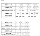
図14は、調整用スイッチ600のチャンネルに応じた第1音量段階および第1光量段階と、チャンネルに応じて調整可能に予め定められた光量範囲および音量範囲との関係を説明する。調整用スイッチ600のチャンネルは、「0」〜「F」の16段階に分かれている。つまり、店員が設定する音量および光量の段階(第1音量段階、第1光量段階に対応)は、16段階に分かれている。調整用スイッチ600が操作されてチャンネルが設定されたときには、当該チャンネルに対応して定められている初期表示(音量)および初期表示(光量)欄に記載の音量段階および光量段階が設定される。   FIG. 14 illustrates the relationship between the first volume level and the first light level corresponding to the channel of the adjustment switch 600 and the predetermined light quantity range and volume range that can be adjusted according to the channel. The channel of the adjustment switch 600 is divided into 16 stages of “0” to “F”. That is, the steps of the volume and the amount of light set by the clerk (corresponding to the first volume level and the first level of light) are divided into 16 levels. When a channel is set by operating the adjustment switch 600, a volume level and a light level described in the initial display (volume) and initial display (light quantity) fields defined for the channel are set.

たとえば、調整用スイッチ600のチャンネル「0」に対応して、音量の初期表示として「2」、光量の初期表示として「30%」が定められている。また、調整用スイッチ600のチャンネル「9」に対応して、音量の初期表示として「14」、光量の初期表示として「100%」が定められている。   For example, “2” is set as the initial display of the volume and “30%” is set as the initial display of the light amount corresponding to the channel “0” of the adjustment switch 600. In addition, “14” is set as the initial display of the volume, and “100%” is set as the initial display of the light amount, corresponding to the channel “9” of the adjustment switch 600.

また、各チャンネルには、遊技者の操作により調整可能な音量範囲および光量範囲(実際の音量範囲、実際の光量範囲)が対応付けて定められている。実際の音量範囲および実際の光量範囲のうちから、遊技者の操作に応じて音量段階および光量段階が設定される。なお、図14における実際の音量範囲における括弧内の数字は、遊技者が設定する第2音量段階に対応する音量表示であり、図15に示す設定画面610の音量設定領域610aに示された数字に対応する。音量および光量の値は、大きいほど、音量および光量が大きくなる。   In addition, a volume range and a light amount range (actual volume range, actual light amount range) that can be adjusted by a player's operation are defined in association with each channel. From the actual sound volume range and the actual light amount range, a sound volume stage and a light intensity stage are set according to the operation of the player. The number in parentheses in the actual volume range in FIG. 14 is a volume display corresponding to the second volume level set by the player, and is a number displayed in the volume setting area 610a of the setting screen 610 shown in FIG. Corresponding to The sound volume and the light amount increase as the values of the sound volume and the light amount increase.

まず、音量について説明する。たとえば、調整用スイッチ600のチャンネルが「0」〜「4」の範囲内で設定されたときには、実際の音量を「2」〜「14」の範囲内から設定可能である。調整用スイッチ600のチャンネルが「5」〜「9」の範囲内で設定されたときには、実際の音量は「10」〜「22」の範囲内から設定可能である。なお、調整用スイッチ600のチャンネルが「A」〜「F」の範囲内で設定されたときには、実際の音量が固定値となる。たとえば、調整用スイッチ600のチャンネルが「A」に設定されたときには、実際の音量は「2」に固定される。   First, the volume will be described. For example, when the channel of the adjustment switch 600 is set in the range of “0” to “4”, the actual volume can be set in the range of “2” to “14”. When the channel of the adjustment switch 600 is set within the range of “5” to “9”, the actual volume can be set within the range of “10” to “22”. When the channel of the adjustment switch 600 is set within the range of “A” to “F”, the actual volume becomes a fixed value. For example, when the channel of the adjustment switch 600 is set to “A”, the actual volume is fixed to “2”.

次に、光量について説明する。たとえば、調整用スイッチ600のチャンネルが「0」〜「3」の範囲内で設定されたときには、実際の光量は「30%」、「65%」、および「100%」のいずれかに設定可能である。調整用スイッチ600のチャンネルが「4」〜「9」の範囲内で設定されたときには、実際の光量は「50%」、「75%」、および「100%」のいずれかに設定可能である。なお、調整用スイッチ600のチャンネルが「A」〜「F」の範囲内で設定されたときには、実際の光量が固定値となる。たとえば、調整用スイッチ600のチャンネルが「A」または「B」に設定されたときには、実際の音量は「30%」に固定される。   Next, the amount of light will be described. For example, when the channel of the adjustment switch 600 is set within the range of “0” to “3”, the actual light amount can be set to any of “30%”, “65%”, and “100%”. It is. When the channel of the adjustment switch 600 is set within the range of “4” to “9”, the actual light amount can be set to any of “50%”, “75%”, and “100%”. . When the channel of the adjustment switch 600 is set within the range of “A” to “F”, the actual light amount becomes a fixed value. For example, when the channel of the adjustment switch 600 is set to “A” or “B”, the actual volume is fixed to “30%”.

次に、設定画面610について説明する。図15は、音量および光量の設定画面について説明する。設定画面610は、たとえば、客待ちの状態においてプッシュボタン31Bを操作することにより画像表示装置5に表示される。   Next, the setting screen 610 will be described. FIG. 15 illustrates a setting screen for the volume and the light amount. The setting screen 610 is displayed on the image display device 5 by operating the push button 31B while waiting for a customer, for example.

設定画面610では、音量設定領域610aにおいて、調整用スイッチ600のチャンネルに応じて調整可能な実際の音量範囲が表示される。これを音量表示ともいう。さらに、現在設定されている音量に対応する数字は、強調表示(点滅表示、選択項目の色を変化させる表示など)される。設定画面610では、光量設定領域610bにおいて、調整用スイッチ600のチャンネルに応じて調整可能な実際の光量範囲が表示される。これを光量表示ともいう。さらに、現在設定されている光量に対応する数字は、強調表示(点滅表示、選択項目の色を変化させる表示など)される。これにより、遊技者は、初期表示の画面(強調表示された数字)を確認することによって、現在の音量および光量を認識することができる。また、遊技者は、所定の変更操作を行うことによって強調表示を移動させ、音量段階および光量段階を変更することができる。たとえば、遊技者は、プッシュボタン31Bを短く押すことによって強調表示を右に移動させることができる。そして、もっとも右に移動した状態からさらにプッシュボタン31Bを押すと、強調表示はMINである左側に飛ぶ。また、プッシュボタン31Bを長く押すことによって、変更させる強調表示を音量設定領域610aにするか光量設定領域610bとするかを選択することができる。   On the setting screen 610, an actual volume range that can be adjusted according to the channel of the adjustment switch 600 is displayed in the volume setting area 610a. This is also called a volume display. Further, the number corresponding to the currently set volume is highlighted (blinking display, display for changing the color of the selected item, etc.). On the setting screen 610, an actual light amount range that can be adjusted according to the channel of the adjustment switch 600 is displayed in the light amount setting area 610b. This is also called a light quantity display. Further, the number corresponding to the currently set light amount is highlighted (blinking display, display for changing the color of the selected item, etc.). Thereby, the player can recognize the current volume and light amount by checking the screen of the initial display (the highlighted number). Further, the player can move the highlighted display by performing a predetermined change operation, and change the volume level and the light level. For example, the player can move the highlight to the right by pressing the push button 31B briefly. Then, when the push button 31B is further pressed from the state where it has been moved to the rightmost, the highlighted display jumps to the left side which is MIN. Further, by pressing the push button 31B for a long time, it is possible to select whether the highlighted display to be changed is the volume setting area 610a or the light quantity setting area 610b.

さらに、設定画面610では、キャラクタ演出領域610cにおいて、遊技中に実際に用いられる演出画面の一部が表示され、当該演出をサンプルに用いて遊技者が音量および光量を設定することができる。具体的には、遊技者が第2音量段階を上げれば、味方キャラクタの音声(図15の例では、「参ったか!!」の音声)の音量が上がり、第2音量段階が最大から最少に移行すると、味方キャラクタの音声の音量が下がる。また、遊技者が第2光量段階を上げれば、演出の画面の光量が上がって明るくなり、第2光量段階が最大から最少に移行すると、演出の画面の光量が下がって暗くなる。このように、遊技中の実際の演出を例にして演出中の音量および光量の設定を行うことができるため、遊技者が容易に設定を行いやすい。   Further, on the setting screen 610, a part of the effect screen actually used during the game is displayed in the character effect area 610c, and the player can set the volume and light amount using the effect as a sample. Specifically, if the player raises the second volume level, the volume of the voice of the ally character (in the example of FIG. 15, the voice of “Hello!”) Increases, and the second volume level decreases from the maximum to the minimum. After the transition, the sound volume of the voice of the ally character decreases. Also, when the player raises the second light level, the light amount of the effect screen increases and becomes brighter, and when the second light level shifts from the maximum to the minimum, the light amount of the effect screen decreases and darkens. As described above, the volume and the light amount during the performance can be set by taking the actual performance during the game as an example, so that the player can easily perform the setting.

以上のように、店員による調整用スイッチ600への操作や遊技者によるプッシュボタン31Bなどへの操作に応じて、演出制御用CPU120は、LED221〜223、遊技効果ランプ9、及びLED541〜543の光量、スピーカ8L、8Rの音量を調整し、当該光量および音量となるように、LED221〜223、遊技効果ランプ9、及びLED541〜543の光量、スピーカ8L、8Rの音量を制御する。具体的に、演出制御用CPU120は、調整後の光量に応じてランプ制御基板14を制御し、調整後の音量に応じて音声制御基板13を制御する。   As described above, in response to the operation of the adjustment switch 600 by the clerk or the operation of the push button 31B by the player, the effect control CPU 120 sets the light amounts of the LEDs 221 to 223, the game effect lamp 9, and the LEDs 541 to 543. Then, the sound volumes of the speakers 8L and 8R are adjusted, and the light amounts of the LEDs 221 to 223, the game effect lamp 9, and the LEDs 541 to 543, and the sound volumes of the speakers 8L and 8R are controlled so as to obtain the light amounts and the sound volumes. Specifically, the effect control CPU 120 controls the lamp control board 14 according to the adjusted light amount, and controls the audio control board 13 according to the adjusted volume.

以上説明したように、本発明の実施形態に係るパチンコ遊技機1では、一般入賞口24bに進入した遊技球の流路が、LED223から出射された光の光路となっている。これにより、一般入賞口24bに進入し流下する遊技球に光を照射する入賞演出を実行することができる。これにより、遊技者は一般入賞口24bに進入した遊技球に気づくことができるとともに、視認される遊技球は光を反射して光り輝くことになる。これにより演出効果を高めることができる。   As described above, in the pachinko gaming machine 1 according to the embodiment of the present invention, the flow path of the game ball that has entered the general winning opening 24b is an optical path of light emitted from the LED 223. As a result, it is possible to execute a winning effect of irradiating the game balls that enter the general winning opening 24b and flow down with light. As a result, the player can notice the game ball that has entered the general winning opening 24b, and the visually recognized game ball reflects light and shines. As a result, the effect can be enhanced.

また、図5に示すように、光を照射され遊技球が光を反射する、矢印Yで示す第1所定領域の前後には、遊技球が光を反射しない区間が設定されている。これにより、LED223を常時発光させていたとしても、一般入賞口24bに進入し流下する遊技球が突然光り輝く入賞演出を実行できる。このような入賞演出は、あたかもセンサ等により遊技球を検出したことに基づいて発光手段を発光させる演出と同様の効果を有する。このように本発明では、センサ等を設けず、制御に負担をかけずに演出効果を高めることが可能となる。   Also, as shown in FIG. 5, before and after the first predetermined area indicated by the arrow Y where light is irradiated and the game ball reflects light, a section where the game ball does not reflect light is set. As a result, even if the LED 223 is constantly lit, it is possible to execute a prize-winning effect in which a game ball entering the general winning opening 24b and flowing down suddenly shines. Such a winning effect has the same effect as the effect of causing the light emitting means to emit light as if a game ball was detected by a sensor or the like. As described above, according to the present invention, it is possible to enhance the effect without providing a sensor or the like and imposing a burden on the control.

また、第1所定領域を流下する遊技球は、空洞部231a(遊技球の流路及び導光部234に入射する光を遮り暗くする。なお、空洞部231aと導光部234とを照らすLED223は、パチンコ遊技機1の電源が投入されている間、常に発光されている。これにより、空洞部231a及び導光部234に光が照射されていることに慣れている遊技者は、空洞部231a及び導光部234が暗くなったことに気づきやすい。これと同時に、あるいはこの後すぐに、遊技球が光輝く入賞演出を実行することができる。これにより、周囲を暗くしたなかで、遊技球を光輝かせることができるため、演出効果を向上させることができる。   Further, the game ball flowing down the first predetermined area blocks and darkens the light entering the cavity 231a (the flow path of the game ball and the light guide 234. The LED 223 illuminating the cavity 231a and the light guide 234). Is always lit while the power of the pachinko gaming machine 1 is turned on, so that a player who is accustomed to irradiating the cavity 231a and the light guide 234 with the light can use the cavity. It is easy to notice that the 231a and the light guide portion 234 have become dark, and at the same time or immediately thereafter, a winning prize effect in which the game balls shine can be executed. Since the sphere can be made to shine, the effect of production can be improved.

また、遊技球に光を照射する発光手段(装飾体200)は、遊技球が流下する遊技盤面2aの後方に設けられている。これにより、一般入賞口24bに進入しない遊技球には光を照射することなく、一般入賞口24bに進入した遊技球のみに確実に光を照射することができる。これにより、一般入賞口24bに進入し流下する遊技球は突然光を反射し光輝くことができる。これにより、演出効果をより高めることが可能となる。   The light emitting means (decorative body 200) for irradiating the game balls with light is provided behind the game board surface 2a on which the game balls flow. Thus, it is possible to reliably irradiate only the game balls that have entered the general winning opening 24b without irradiating the game balls that do not enter the general winning opening 24b. As a result, the game balls that enter the general winning opening 24b and flow down can suddenly reflect light and shine. This makes it possible to further enhance the effect.

また、遊技球経路400は、進入口400aの直後からおおよそ90度下方へと流路を変更させた屈曲部400bを有している。そして、この屈曲部400bを通過する遊技球にも光を届かせ該光を反射するようにしている(図5、6参照)。遊技球は、屈曲部400bを通過する際、移動する方向を大きく変えるため移動速度が遅くなる。従って、移動速度が遅くなった分だけ、長い時間にわたり遊技球を光り輝かせることができ、演出効果を高めることができる。また、遊技球の移動方向が大きく変わるため、それに伴い遊技球に反射される光の態様が大きく変化する。このように遊技球の移動に伴い、光の反射態様を変化させることができ演出効果を高めることができる。   In addition, the game ball path 400 has a bent portion 400b whose flow path is changed approximately 90 degrees downward immediately after the entrance 400a. The light reaches the game balls passing through the bent portion 400b and is reflected (see FIGS. 5 and 6). When the game ball passes through the bent portion 400b, the moving speed is greatly reduced because the moving direction is greatly changed. Therefore, the game ball can be made to shine for a long time by an amount corresponding to the slowing down of the moving speed, and the effect can be enhanced. Further, since the moving direction of the game ball changes greatly, the mode of the light reflected on the game ball changes accordingly. As described above, with the movement of the game ball, the light reflection mode can be changed, and the effect can be enhanced.

また、装飾体200に設けられたLED221〜223は、一般入賞口24bに進入した遊技球に光を照射し該光を反射させるだけでなく、導光部232〜234の光の照射も兼ねている。これにより、遊技球に光を反射させるための発光手段を別途設ける必要がなく、コストを抑制することができる。   The LEDs 221 to 223 provided in the decorative body 200 not only irradiate and reflect the light to the game balls that have entered the general winning opening 24b, but also irradiate the light from the light guides 232 to 234. I have. Thus, it is not necessary to separately provide a light emitting means for reflecting light on the game ball, and the cost can be suppressed.

また、LED541〜543から出射された光の一部は、図12(b)に示すように上方に向かう。上方に向かった一部の光は、リブ534に入射し、空中との境界面である全反射面534cで全反射させている。この全反射した光は遊技者に向かうように構成されている。これにより、リブ534が設けられた位置で輝く強い光を遊技者に視認させることができ、リブ534を効果的に発光させることができる。   In addition, part of the light emitted from the LEDs 541 to 543 goes upward as shown in FIG. Part of the light directed upward enters the rib 534 and is totally reflected by a total reflection surface 534c which is a boundary surface with the air. This totally reflected light is configured to travel toward the player. Thereby, a strong light shining at the position where the rib 534 is provided can be visually recognized by the player, and the rib 534 can emit light effectively.

なお、LED541〜543から光が出射され、出射された光が全反射されて遊技者に届くまでの光路上には、例えば凹凸544のような光を拡散させる部位は存在せず、平坦化された表面しか存在していない。そのため、LED541〜543からの光は拡散されずに、直接遊技者に視認されることになる。これにより、リブ534が設けられた位置で輝く強い光を遊技者に視認させることができ、リブ534を効果的に発光させることができる。   In addition, on the optical path from when the light is emitted from the LEDs 541 to 543 and the emitted light is totally reflected and reaches the player, there is no portion such as the unevenness 544 that diffuses the light, and the light is flattened. There is only a surface. Therefore, the light from the LEDs 541 to 543 is not diffused and is directly recognized by the player. Thereby, a strong light shining at the position where the rib 534 is provided can be visually recognized by the player, and the rib 534 can emit light effectively.

また、LED541〜543から出射され、案内部533aに向かった光のうち、リブ534に入射しなかった光は、リブ534周囲の案内部533a、ベース板510に形成された通過孔515(図8)、及び第2可動装置560の流路560a(図10)を明るく照射する。この案内部533a、通過孔515、及び流路560aは、特別可変入賞球装置7に入賞した遊技球の流路である。そのため、案内部533aや通過孔515を通過する遊技球によって、照射されていた光が遮られて暗くなる部分が形成される一方、遊技球に光が反射して光輝く部分も形成される。このように、通過する遊技球により、光の見え方を刻々と変化させることができ、遊技者を魅了する演出を提供することができる。   Further, of the light emitted from the LEDs 541 to 543 and directed to the guide portion 533a, the light that has not entered the rib 534 is the guide portion 533a around the rib 534 and the passage hole 515 formed in the base plate 510 (FIG. 8). ) And the flow path 560a (FIG. 10) of the second movable device 560 is brightly irradiated. The guide portion 533a, the passage hole 515, and the flow path 560a are flow paths for game balls that have won the special variable winning ball device 7. Therefore, the game ball passing through the guide portion 533a and the passage hole 515 forms a portion where the irradiated light is blocked and darkened, and a portion where the light is reflected by the game ball and shines. In this way, the appearance of light can be changed every moment by the passing game ball, and an effect that can attract the player can be provided.

また、LED541〜543の光は、リブ534、案内部533a、及び通過孔515に向かうだけでなく、その一部は前方にあるカバー体530の凹凸544(図12(b))で拡散され、そのままカバー体530から前方へ出射される。これにより、LED541〜543の光によって様々な部位を発光させることができ、演出効果を高めることができる。   In addition, the light of the LEDs 541 to 543 not only goes to the rib 534, the guide portion 533a, and the passage hole 515, but also a part of the light is diffused by the unevenness 544 (FIG. 12B) of the cover body 530 at the front. The light is emitted forward from the cover body 530 as it is. Thereby, various parts can be made to emit light by the light of the LEDs 541 to 543, and the effect can be enhanced.

また、強い光を発光するリブ534が形成されている位置に、星形図形536を配置している。これにより、まるで星が輝いているかのような演出を実行することができる。   Further, a star-shaped figure 536 is arranged at a position where a rib 534 that emits strong light is formed. This makes it possible to execute an effect as if the stars were shining.

また、図11に示すように、普通可変入賞球装置6Bにおいて右下方向(第1方向)に流下した遊技球が、特別可変入賞球装置7において右下方向(第1方向)とは異なる左下方向(第2方向)に流下可能な態様で、2つの可変入賞装置を上下方向に並べて配置することにより、可変入賞装置の設置場所を確保しやすくすることができる。   As shown in FIG. 11, the game ball that has flowed down in the lower right direction (first direction) in the normal variable winning ball device 6B is different from the lower left direction in the special variable winning ball device 7 in the lower right direction (first direction). By arranging two variable prize apparatuses side by side in the vertical direction in such a manner that the variable prize apparatuses can flow in the direction (second direction), it is possible to easily secure an installation place of the variable prize apparatuses.

また、普通可変入賞球装置6Bにおける遊技球の流下方向(右下方向)と、特別可変入賞球装置7における遊技球の流下方向(左下方向)とが逆方向であることにより、遊技球の流下方向の逆方向への変更時に一旦流下速度が0になる等、流下方向の逆方向への変更に基づいて、特別可変入賞球装置7を流下する遊技球を減速させることが可能となる。   In addition, the flowing direction of the game ball (lower right direction) in the normal variable winning ball device 6B and the flowing direction (lower left direction) of the game ball in the special variable winning ball device 7 are opposite to each other, so that the game ball flows down. It is possible to decelerate the game balls flowing down the special variable prize ball device 7 based on the change in the flowing direction in the reverse direction, such as once the flowing speed becomes 0 when the direction is changed in the reverse direction.

また、ベース体510に形成された規制片516と、カバー体530に形成された規制片536とを交互に流路に突出させることにより、特別可変入賞球装置7を流下する遊技球の勢いが抑制される。これにより、可動板561が閉鎖しているときの特別可変入賞球装置7における遊技球の滞在期間を長期化することができる。これにより、特別可変入賞球装置7において遊技球をより一層入賞させやすくすることができる。   In addition, the regulation pieces 516 formed on the base body 510 and the regulation pieces 536 formed on the cover body 530 are alternately projected into the flow path, so that the momentum of the game balls flowing down the special variable prize ball device 7 is increased. Be suppressed. Thereby, the stay period of the game ball in the special variable winning ball device 7 when the movable plate 561 is closed can be lengthened. This makes it easier for the special variable winning prize ball device 7 to win a game ball.

また、前述した実施の形態におけるパチンコ遊技機1には、LEDなどの発光手段として、遊技の進行に応じて制御される発光手段(第1特別図柄表示器4A、第2特別図柄表示器4B、普通図柄表示器20、第1保留表示器25A、第2保留表示器25B、及び普図保留表示器25Cを構成する各LEDなど)と、演出の進行に応じて制御される発光手段(LED221〜223、遊技効果ランプ9、LED541〜543など)とが搭載されている。店員による調整用スイッチ600への操作や遊技者によるプッシュボタン31Bなどへの操作に応じて、発光手段のうち演出の進行に応じて制御される発光手段の光量については調整可能である一方、遊技の進行に応じて制御される発光手段の光量については調整できないように構成されている。このため、遊技の進行に応じて制御される発光手段の光量が調整されることにより遊技の進行が阻害されてしまうといった不都合の発生を防止できる。その結果、LED221〜223、遊技効果ランプ9、LED541〜543などの光量を適切に調整可能としつつ、遊技者に不満感を抱かせてしまうことを防止できる。   In the pachinko gaming machine 1 according to the above-described embodiment, as light emitting means such as LEDs, light emitting means (first special symbol display 4A, second special symbol display 4B, Each of the ordinary symbol display 20, the first reservation display 25A, the second reservation display 25B, and the LEDs constituting the general reservation display 25C, and light emitting means (LEDs 221 to 221) controlled according to the progress of the effect. 223, game effect lamps 9, LEDs 541 to 543, etc.). According to the operation of the adjustment switch 600 by the clerk or the operation of the push button 31B by the player, the light amount of the light emitting means of the light emitting means, which is controlled in accordance with the progress of the effect, can be adjusted. The light amount of the light emitting means controlled in accordance with the progress of the control cannot be adjusted. For this reason, it is possible to prevent the inconvenience that the progress of the game is hindered by adjusting the light amount of the light emitting means controlled according to the progress of the game. As a result, it is possible to appropriately adjust the light amounts of the LEDs 221 to 223, the game effect lamp 9, the LEDs 541 to 543, and to prevent the player from feeling dissatisfied.

この発明は、上記実施の形態に限定されず、様々な変形及び応用が可能である。上記実施の形態では、一般入賞球装置24に進入した遊技球にLED223からの光を反射させていたが、遊技領域10を流下する遊技球が進入可能な他の進入口であっても、同様にこの発明を適用できる。例えば、普通入賞球装置6A等の他の入賞球装置であってよいし、いずれの入賞球装置にも入賞しなかった遊技球が進入するアウト口であってもよいし、遊技球を所定位置まで導くためのワープ経路であっても本発明を適用することができる。   The present invention is not limited to the above embodiment, and various modifications and applications are possible. In the above embodiment, the light from the LED 223 is reflected on the game ball that has entered the general winning ball device 24. However, the same applies to other entrances where the game ball flowing down the game area 10 can enter. The present invention can be applied to the present invention. For example, another winning ball device such as the normal winning ball device 6A may be used, a game ball that has not won any of the winning ball devices may be an out port to enter, or the game ball may be moved to a predetermined position. The present invention can be applied even to a warp route for leading to the same.

また、一般入賞装置24に進入した遊技球に光を照らす光学手段としてLED223のみを説明したが、互いに異なる色の光を発光する複数のLEDを設けて、様々な色の光で、遊技球、流下路、及び導光部234を照射するようにしてもよい。また、色の変化を刻々と変化させてもよいし、出射する光の量も変化させてもよい。あるいは、大当り中や、リーチ演出中といった特定の場面のみに照射する照射する光の色や量を変化させるようにしてもよい。   Also, only the LED 223 has been described as an optical means for illuminating a game ball that has entered the general winning device 24. However, a plurality of LEDs that emit light of different colors are provided, and the game ball, The flow path and the light guide section 234 may be irradiated. Further, the change in color may be changed every moment, or the amount of emitted light may be changed. Alternatively, the color or amount of light to be applied only to a specific scene such as a big hit or a reach effect may be changed.

また、遊技球に光を照射する発光手段と、遊技球の流路との関係についても、上記実施の形態に限定されない。入賞球装置に進入した遊技球の流路内に光を照射する光学手段があれば、入賞球装置に進入した遊技球は光を反射することが可能である。また、光学手段による光の照射範囲も、入賞球装置に進入後の流路に限定されていることが好ましいが、進入直前の遊技球に光が当たり反射する態様であってもよい。図16は、一般入賞口の近傍に光学手段が取り付けられた他の例を説明するための説明図である。図16では、説明するLEDの全てを1つの図に記している。例えば、LED701に示すように、一般入賞口24bを構成する前面の流路壁に光学手段を取り付けてもよいし、LED702に示すように下面の流路壁に光学手段を取り付けてもよい。これにより、遊技球は、一般入賞口24bに進入した後すぐに、照射された光を反射する。また、LED703に示すように流路壁の上面に取り付けてもよいし、LED704に示すように遊技球経路400に取り付けてもよい。これにより、一般入賞口24bに進入後の遊技球に光が照射され、該光が遊技球表面で反射される。これらのように、遊技球の流下路を形成する壁体に直接光学手段をとりつけてもよい。これにより、流下する遊技球に、近くで発光する光学手段からの光を照射することができ、遊技球を光輝かせることができる。また、LED705に示すように、遊技盤面2aに突出部706を形成し、この突出部706に光学手段を設けてもよい。これにより、一般入賞口24bに進入する直前の遊技球にも光を照射することができる。   Also, the relationship between the light emitting means for irradiating the game balls with light and the flow paths of the game balls is not limited to the above embodiment. If there is optical means for irradiating light in the flow path of the game ball that has entered the winning ball device, the game ball that has entered the winning ball device can reflect light. Also, the range of light irradiation by the optical means is preferably limited to the flow path after entering the winning prize ball device, but a mode in which light hits and reflects on a game ball immediately before entering may be used. FIG. 16 is an explanatory diagram for explaining another example in which the optical means is attached near the general winning opening. In FIG. 16, all of the LEDs to be described are shown in one figure. For example, as shown by the LED 701, the optical means may be attached to the front channel wall constituting the general winning opening 24b, or the optical means may be attached to the lower channel wall as shown by the LED 702. As a result, the game ball reflects the irradiated light immediately after entering the general winning opening 24b. Further, it may be attached to the upper surface of the channel wall as shown by the LED 703, or may be attached to the game ball path 400 as shown by the LED 704. As a result, the game ball after entering the general winning opening 24b is irradiated with light, and the light is reflected on the surface of the game ball. As described above, the optical means may be directly attached to the wall forming the downflow path of the game ball. Thus, the light from the optical means that emits light nearby can be applied to the flowing game ball, and the game ball can be made to shine. Further, as shown by the LED 705, a projection 706 may be formed on the game board surface 2a, and the projection 706 may be provided with an optical unit. Thereby, it is possible to irradiate the game ball immediately before entering the general winning opening 24b.

このように、光学手段を取り付ける位置としての第1所定領域や一般入賞口の「近傍」とは、第1所定領域を通る遊技球や、一般入賞口に進入する遊技球に、光学手段から発せられた光が反射されて、遊技球が輝いているとの印象を与える程度に近いという意味である。そのためには、光学手段と、第1所定領域を通る遊技球や一般入賞口に進入する遊技球とが隣接するような距離であったり、両者の距離が遊技球直径の数個分(例えば3個)以内であったりすることが好ましい。あるいは、第1所定領域を通る遊技球や一般入賞口に進入する遊技球に光を照射する光学手段であるため、その他の演出用の光学手段よりも、第1所定領域や一般入賞口から近い位置に配置されていることが好ましい。これにより、光学手段から発せられた光によって、遊技球を光輝かせることができる。   As described above, the “near” of the first predetermined area or the general winning opening as a position where the optical means is attached is defined as a game ball passing through the first predetermined area or a game ball entering the general winning opening. This means that the reflected light is close enough to give an impression that the game ball is shining. For that purpose, the optical means and the game ball passing through the first predetermined area or the game ball entering the general winning opening are adjacent to each other, or the distance between them is equal to several game ball diameters (for example, 3 mm). ). Alternatively, since the optical means irradiates light to a game ball passing through the first predetermined area or a game ball entering the general winning opening, it is closer to the first predetermined area or the general winning opening than other optical means for effect. It is preferred that they are arranged at positions. Thereby, the game ball can be made to shine by the light emitted from the optical means.

また、遊技球に光を照射する図5等に示すLED223、及び図16に示すLED701〜705のうちから複数のLEDをパチンコ遊技機1に設置してもよい。これにより、一般入賞球装置24に進入する直前の遊技球から、屈曲部400bを通過した後の遊技球まで、光を照射することができる。また、設置した複数のLEDの発光色を異ならせることで、流下する遊技球が反射する光の色を変化させることができる。これにより、流下する遊技球が反射する光の色を変化させることができ、演出効果を向上させることができる。   In addition, a plurality of LEDs may be installed in the pachinko gaming machine 1 out of the LEDs 223 shown in FIG. 5 and the like for irradiating the game balls with light, and the LEDs 701 to 705 shown in FIG. Thus, light can be emitted from the game ball immediately before entering the general winning ball device 24 to the game ball after passing through the bent portion 400b. Further, by making the emission colors of the plurality of LEDs installed different, it is possible to change the color of light reflected by the flowing game balls. As a result, the color of the light reflected by the flowing game balls can be changed, and the effect can be improved.

また、図12に示すように、光を全反射するリブ534は、特別可変入賞球装置7に設けられていると説明したが、遊技領域10を流下する遊技球が進入可能な他の進入口であっても同様に適用可能である。例えば、図6に示す一般入賞球装置24に形成されたリブ24cの近傍に光学手段を配置し、出射した光をリブ24cで反射させる態様であってもよい。また、遊技球を所定箇所まで導くためのワープ路の入口に形成されたリブに光を照射する態様であってもよい。   Also, as shown in FIG. 12, the rib 534 that totally reflects light is described as being provided in the special variable winning ball device 7, but other entrances through which game balls flowing down the game area 10 can enter. However, the present invention can be similarly applied. For example, the optical means may be arranged near the rib 24c formed on the general winning ball apparatus 24 shown in FIG. 6, and the emitted light may be reflected by the rib 24c. Further, a mode in which light is applied to a rib formed at an entrance of a warp path for guiding a game ball to a predetermined location may be adopted.

なお、リブと、リブに光を照射する光学手段との位置関係は、図12に示すような関係に限定されない。例えば、光学手段を、リブの真下(例えば、矢視B−Bを示すライン上)に設けてもよい。これにより、光学手段からの光を、直接リブに入射しやすくすることができる。このように配置した光学手段からの光を、遊技者に向けて反射させるためには、リブの全反射面の向きと光学手段位置とは所定の位置関係にある必要がある。本発明では、これらの位置関係を適切に設定することにより、光学手段の光をリブで反射させた明るい光を視認させることができる。   The positional relationship between the rib and the optical means for irradiating the rib with light is not limited to the relationship shown in FIG. For example, the optical means may be provided directly below the rib (for example, on a line showing the arrow BB). This makes it easier for the light from the optical means to directly enter the rib. In order to reflect the light from the optical means arranged as described above toward the player, it is necessary that the direction of the total reflection surface of the rib and the position of the optical means have a predetermined positional relationship. In the present invention, by appropriately setting these positional relationships, it is possible to visually recognize bright light obtained by reflecting the light of the optical unit by the rib.

また、リブに光を照射するLED541、LED542、及びLED543が発する光の色については特に言及しなかったが、同色の光を発光するLEDであってもよいし、互いに異なる色の光を発光するLEDであってもよい。例えば、図12に示すように、リブ534から略等距離にあるLED541及びLED542において、LED541を赤色LEDとし、LED542を青色LEDとしてもよい。これにより、リブ534で反射される光を、赤色と青色とを混色させた赤紫色とすることができ、星形図形536から赤紫色の光が光っているかのように視認させることができる。また、互いに異なる色の光を発するLEDを、リブ534の近傍に3個以上設け、発光するLEDを制御することで、リブ534で反射される光の色を変化させてもよい。これにより、遊技者を魅了する演出を実行することができる。   In addition, although the colors of the light emitted by the LEDs 541, 542, and 543 that irradiate the ribs with light are not particularly described, LEDs that emit light of the same color may be used, or light of different colors may be emitted. It may be an LED. For example, as shown in FIG. 12, among the LEDs 541 and the LEDs 542 substantially equidistant from the rib 534, the LED 541 may be a red LED and the LED 542 may be a blue LED. Accordingly, the light reflected by the rib 534 can be made to be red-purple mixed with red and blue, and the star-shaped figure 536 can be visually recognized as if red-red light is shining. Alternatively, three or more LEDs that emit light of different colors may be provided near the rib 534, and the color of the light reflected by the rib 534 may be changed by controlling the LED that emits light. Thereby, it is possible to execute an effect that attracts the player.

また、カバー体530において、強く光り輝くリブ534の位置に星形図形536を配置したが、他の図形を配置してもよく、例えば太陽の図やライトの図であってもよいし、不規則な凹凸をカバー体530の前面に形成して、光を拡散して出射させるようにしてもよい。   Further, in the cover body 530, the star-shaped figure 536 is arranged at the position of the rib 534 that shines strongly, but other figures may be arranged, for example, a figure of the sun or a figure of the light, or an irregular figure. The unevenness may be formed on the front surface of the cover body 530 to diffuse and emit light.

また、前述した実施の形態では、光量及び音量の調整手段として、演出制御基板12に搭載された演出制御用CPU120を例示した。しかし、調整手段は、これに限らず、音声制御基板13に搭載されている回路やランプ制御基板14に搭載されている回路であってもよい   In the above-described embodiment, the effect control CPU 120 mounted on the effect control board 12 has been exemplified as the light amount and sound volume adjusting means. However, the adjusting means is not limited to this, and may be a circuit mounted on the audio control board 13 or a circuit mounted on the lamp control board 14.

また、主基板11に搭載された遊技制御用マイクロコンピュータ100が遊技の進行に応じて演出内容を決定するとともに、パチンコ遊技機1に搭載されているLEDなどの発光手段のうち、遊技の進行に応じて制御される発光手段(第1特別図柄表示器4A、第2特別図柄表示器4B、普通図柄表示器20、第1保留表示器25A、第2保留表示器25B、及び普図保留表示器25Cを構成する各LED)と、演出の進行に応じて制御される発光手段(LED221〜223、遊技効果ランプ9、LED541〜543)との双方を制御するようにしてもよい。この場合においても、遊技の進行に応じて制御される発光手段ではなく、演出の進行に応じて制御される発光手段のみの光量を調整するようにしてもよい。調整手段として、たとえば、遊技制御用マイクロコンピュータ100が調整後の光量に応じて演出の進行に応じて制御される発光手段を制御してもよく、また、ランプ制御基板14が調整後の光量に応じて演出の進行に応じて制御される発光手段を制御するようにしてもよい。なお、遊技制御用マイクロコンピュータ100により制御される発光手段は、遊技の進行に応じて制御されるすべての発光手段と、演出の進行に応じて制御される一部またはすべての発光手段とを含むものであってもよい。このように構成した場合においても、前述した実施の形態と同様の効果を奏する。   In addition, the game control microcomputer 100 mounted on the main board 11 determines the effect contents in accordance with the progress of the game, and, among the light emitting means such as the LEDs mounted on the pachinko gaming machine 1, The light emitting means (the first special symbol display 4A, the second special symbol display 4B, the ordinary symbol display 20, the first reservation indicator 25A, the second reservation indicator 25B, and the general symbol reservation indicator controlled in accordance with You may make it control both the LED which comprises 25C, and the light emission means (LED221-223, game effect lamp 9, LED541-543) controlled according to the progress of an effect. Also in this case, the light amount of only the light emitting unit controlled according to the progress of the effect may be adjusted instead of the light emitting unit controlled according to the progress of the game. As the adjusting means, for example, the game control microcomputer 100 may control a light emitting means which is controlled in accordance with the progress of the effect according to the adjusted light quantity, and the lamp control board 14 may adjust the light quantity after the adjustment. The light-emitting means controlled according to the progress of the effect may be controlled accordingly. The light emitting means controlled by the game control microcomputer 100 includes all light emitting means controlled according to the progress of the game, and some or all light emitting means controlled according to the progress of the effect. It may be something. Even in the case of such a configuration, the same effects as those of the above-described embodiment can be obtained.

前述した実施の形態においては、調整対象である発光手段の発光態様として、輝度に相当する光量を例示した。しかし、発光態様としては、光量に限らず、発光色や、発光させる発光手段(LED)の個数、発光させる期間、および、これらの組合せなどであってもよい。これにより、調整手段により調整される態様を豊富にすることができる。   In the above-described embodiment, the light amount corresponding to the luminance is exemplified as the light emission mode of the light emitting unit to be adjusted. However, the light emission mode is not limited to the light amount, but may be a light emission color, the number of light emitting means (LEDs) to emit light, a light emission period, a combination thereof, or the like. This makes it possible to enrich the modes adjusted by the adjusting means.

また、例えば、パチンコ遊技機1に隣接して配置されたカードユニットからのエラーコマンド等を受信した主基板11が、接続されたスピーカ(不図示)から警告音を発する構成を有している場合、該スピーカは遊技の進行に応じて制御されるスピーカ(不図示)である。このような、遊技の進行に応じて制御されるスピーカ(不図示)の音量は調整することができない。一方で、演出の進行に応じて制御されるスピーカ(8L、8R)は、店員による調整用スイッチ600への操作や遊技者によるプッシュボタン31Bなどへの操作に応じて調整可能である。   Further, for example, when the main board 11 that has received an error command or the like from a card unit arranged adjacent to the pachinko gaming machine 1 has a configuration that emits a warning sound from a connected speaker (not shown). The speaker is a speaker (not shown) that is controlled in accordance with the progress of the game. Such a sound volume of a speaker (not shown) controlled according to the progress of the game cannot be adjusted. On the other hand, the speakers (8L, 8R) controlled in accordance with the progress of the effect can be adjusted according to the operation of the adjustment switch 600 by the clerk or the operation of the push button 31B by the player.

また、上記実施の形態では、遊技機の一例としてパチンコ遊技機を例示しているが、本発明はこれに限定されるものではなく、例えば、予め定められた球数の遊技球が遊技機内部に循環可能に内封され、遊技者による貸出要求に応じて貸し出された貸出球や、入賞に応じて付与された賞球数が加算される一方、遊技に使用された遊技球数が減算されて記憶される、所謂、封入式遊技機にも本発明を適用可能である。   Further, in the above embodiment, a pachinko gaming machine is exemplified as an example of a gaming machine, but the present invention is not limited to this, and for example, a predetermined number of gaming balls are provided inside the gaming machine. The number of game balls used for the game is subtracted, while the number of rented balls lent in response to a loan request by the player and the number of prize balls awarded in accordance with the winning are added. The present invention is also applicable to a so-called enclosed game machine that stores and stores information.

今回開示された実施の形態はすべての点で例示であって制限的なものではないと考えられるべきである。本発明の範囲は上記した説明ではなくて特許請求の範囲によって示され、特許請求の範囲と均等の意味および範囲内でのすべての変更が含まれることが意図される。   The embodiments disclosed this time are to be considered in all respects as illustrative and not restrictive. The scope of the present invention is defined by the terms of the claims, rather than the description above, and is intended to include any modifications within the scope and meaning equivalent to the terms of the claims.

1 パチンコ遊技機
2 遊技盤
6B 普通可変入賞球装置
7 特別可変入賞球装置
24 一般入賞球装置
24b 一般入賞口
82 ソレノイド
200 装飾体
223 LED
230 レンズ体
231 筒状体
232a、233a、234a 光入射面
234 導光部
240 カバー体
400 遊技球経路
400b 屈曲部
500 入賞球装置ユニット
510 ベース板
520 カバー体
530 カバー体
533 進入口
533a 案内部
534c 全反射面
534 リブ
536 星形図形
541、542、543 LED
550 第1可動装置
551 可動板
560 第2可動装置
561 可動板
DESCRIPTION OF SYMBOLS 1 Pachinko gaming machine 2 Game board 6B Ordinary variable prize ball device 7 Special variable prize ball device 24 General prize ball device 24b General prize port 82 Solenoid 200 Decoration 223 LED
230 Lens body 231 Cylindrical body 232a, 233a, 234a Light incidence surface 234 Light guide section 240 Cover body 400 Game ball path 400b Bent section 500 Winning ball unit 510 Base plate 520 Cover body 530 Cover body 533 Entrance 533a Guide section 534c Total reflection surface 534 Rib 536 Star-shaped figure 541,542,543 LED
550 First movable device 551 movable plate 560 Second movable device 561 movable plate

Claims (1)

遊技が可能な遊技機であって、
遊技媒体が通過可能な所定領域と、
発光可能な発光手段と、
前記所定領域を遊技媒体が通過したことを検出可能な検出手段と、
前記検出手段により遊技媒体の通過が検出されたことにもとづいて遊技価値を付与可能な付与手段と、
遊技の進行に応じて遊技状態を変更可能な状態変更手段と、を備え、
前記発光手段は、
前記所定領域に向けて光を発し、
発した光の少なくとも一部が、前記所定領域を通過する遊技媒体によって遊技者が視認可能な方向に反射される特別反射が行われるとともに、発した光の少なくとも一部が遊技媒体に照射されるときの照射面が遊技媒体が前記所定領域を通過するときに遊技者から見て遊技媒体の後面側から前面側に変化するように該所定領域の近傍に設けられ、
前記所定領域は、前記状態変更手段により変更される遊技状態にかかわらず、遊技媒体が通過可能であり、
前記特別反射は、前記検出手段により遊技媒体の通過が検出される前に行われる、
ことを特徴とする遊技機。
A gaming machine that can play games,
A predetermined area through which game media can pass;
Light emitting means capable of emitting light,
Detecting means for detecting that the game medium has passed through the predetermined area,
Providing means for providing a game value based on the detection of the passage of the game medium by the detecting means,
State change means capable of changing the game state according to the progress of the game,
The light emitting means,
Emit light toward the predetermined area,
At least a part of the emitted light is subjected to a special reflection in which the game medium passing through the predetermined region is reflected in a direction visible to a player, and at least a part of the emitted light is applied to the game medium. The irradiation surface at the time is provided in the vicinity of the predetermined area so as to change from the rear side of the game medium to the front side when viewed from the player when the game medium passes through the predetermined area ,
The predetermined area is capable of passing game media regardless of a game state changed by the state change unit,
The special reflection is performed before the detection means detects the passage of the game medium,
A gaming machine characterized by that:
JP2017122979A 2017-06-23 2017-06-23 Gaming machine Active JP6630706B2 (en)

Priority Applications (1)

Application Number Priority Date Filing Date Title
JP2017122979A JP6630706B2 (en) 2017-06-23 2017-06-23 Gaming machine

Applications Claiming Priority (1)

Application Number Priority Date Filing Date Title
JP2017122979A JP6630706B2 (en) 2017-06-23 2017-06-23 Gaming machine

Publications (3)

Publication Number Publication Date
JP2019005117A JP2019005117A (en) 2019-01-17
JP2019005117A5 JP2019005117A5 (en) 2019-02-28
JP6630706B2 true JP6630706B2 (en) 2020-01-15

Family

ID=65025945

Family Applications (1)

Application Number Title Priority Date Filing Date
JP2017122979A Active JP6630706B2 (en) 2017-06-23 2017-06-23 Gaming machine

Country Status (1)

Country Link
JP (1) JP6630706B2 (en)

Family Cites Families (7)

* Cited by examiner, † Cited by third party
Publication number Priority date Publication date Assignee Title
JP3479551B2 (en) * 1994-04-01 2003-12-15 株式会社Mrd Spherical object detection device
JP3865986B2 (en) * 1999-11-30 2007-01-10 アルゼ株式会社 Game board of bullet ball machine
JP2007275367A (en) * 2006-04-07 2007-10-25 Sansei R & D:Kk Pachinko game machine
JP2008289633A (en) * 2007-05-24 2008-12-04 You Tech:Kk Game apparatus
JP5719233B2 (en) * 2011-05-19 2015-05-13 株式会社ソフイア Game machine
JP6070657B2 (en) * 2014-09-04 2017-02-01 株式会社三洋物産 Game machine
JP2017099433A (en) * 2015-11-30 2017-06-08 株式会社ソフイア Game machine

Also Published As

Publication number Publication date
JP2019005117A (en) 2019-01-17

Similar Documents

Publication Publication Date Title
JP2008161457A (en) Game machine
JP2019118534A (en) Game machine
JP5070407B2 (en) Game machine
JP4803585B2 (en) Electrical equipment for bullet ball machines
JP2007252532A (en) Game machine
JP6630706B2 (en) Gaming machine
JP2009078030A (en) Game machine
JP2018099457A (en) Game machine
JP2018099458A (en) Game machine
JP6573369B2 (en) Game machine
JP6559738B2 (en) Game machine
JP6700244B2 (en) Amusement machine
JP2003126385A (en) Pachinko game machine
JP6700243B2 (en) Amusement machine
JP7205922B2 (en) game machine
JP2019072032A (en) Game machine
JP2019118535A (en) Game machine
JP5060928B2 (en) Game machine
JP2008043428A (en) Center win pocket and game machine with the center win pocket
JP5134923B2 (en) Game machine
JP6835705B2 (en) Game machine
JP2005185368A (en) Pinball game machine
JP2005279024A (en) Game machine
JP2005230195A (en) Pinball machine
JP2005304718A (en) Pinball machine

Legal Events

Date Code Title Description
A621 Written request for application examination

Free format text: JAPANESE INTERMEDIATE CODE: A621

Effective date: 20180724

A521 Request for written amendment filed

Free format text: JAPANESE INTERMEDIATE CODE: A523

Effective date: 20190115

A131 Notification of reasons for refusal

Free format text: JAPANESE INTERMEDIATE CODE: A131

Effective date: 20190409

A977 Report on retrieval

Free format text: JAPANESE INTERMEDIATE CODE: A971007

Effective date: 20190412

A521 Request for written amendment filed

Free format text: JAPANESE INTERMEDIATE CODE: A523

Effective date: 20190605

A131 Notification of reasons for refusal

Free format text: JAPANESE INTERMEDIATE CODE: A131

Effective date: 20190716

A521 Request for written amendment filed

Free format text: JAPANESE INTERMEDIATE CODE: A523

Effective date: 20190909

TRDD Decision of grant or rejection written
A01 Written decision to grant a patent or to grant a registration (utility model)

Free format text: JAPANESE INTERMEDIATE CODE: A01

Effective date: 20191203

A61 First payment of annual fees (during grant procedure)

Free format text: JAPANESE INTERMEDIATE CODE: A61

Effective date: 20191209

R150 Certificate of patent or registration of utility model

Ref document number: 6630706

Country of ref document: JP

Free format text: JAPANESE INTERMEDIATE CODE: R150

R250 Receipt of annual fees

Free format text: JAPANESE INTERMEDIATE CODE: R250

R250 Receipt of annual fees

Free format text: JAPANESE INTERMEDIATE CODE: R250