JP6628811B2 - Manufacturing method of preform and container - Google Patents
Manufacturing method of preform and container Download PDFInfo
- Publication number
- JP6628811B2 JP6628811B2 JP2017552761A JP2017552761A JP6628811B2 JP 6628811 B2 JP6628811 B2 JP 6628811B2 JP 2017552761 A JP2017552761 A JP 2017552761A JP 2017552761 A JP2017552761 A JP 2017552761A JP 6628811 B2 JP6628811 B2 JP 6628811B2
- Authority
- JP
- Japan
- Prior art keywords
- preform
- container
- body portion
- corner
- mold
- Prior art date
- Legal status (The legal status is an assumption and is not a legal conclusion. Google has not performed a legal analysis and makes no representation as to the accuracy of the status listed.)
- Active
Links
Images


Classifications
-
- B—PERFORMING OPERATIONS; TRANSPORTING
- B29—WORKING OF PLASTICS; WORKING OF SUBSTANCES IN A PLASTIC STATE IN GENERAL
- B29B—PREPARATION OR PRETREATMENT OF THE MATERIAL TO BE SHAPED; MAKING GRANULES OR PREFORMS; RECOVERY OF PLASTICS OR OTHER CONSTITUENTS OF WASTE MATERIAL CONTAINING PLASTICS
- B29B11/00—Making preforms
- B29B11/06—Making preforms by moulding the material
- B29B11/08—Injection moulding
-
- B—PERFORMING OPERATIONS; TRANSPORTING
- B29—WORKING OF PLASTICS; WORKING OF SUBSTANCES IN A PLASTIC STATE IN GENERAL
- B29B—PREPARATION OR PRETREATMENT OF THE MATERIAL TO BE SHAPED; MAKING GRANULES OR PREFORMS; RECOVERY OF PLASTICS OR OTHER CONSTITUENTS OF WASTE MATERIAL CONTAINING PLASTICS
- B29B11/00—Making preforms
- B29B11/14—Making preforms characterised by structure or composition
-
- B—PERFORMING OPERATIONS; TRANSPORTING
- B29—WORKING OF PLASTICS; WORKING OF SUBSTANCES IN A PLASTIC STATE IN GENERAL
- B29C—SHAPING OR JOINING OF PLASTICS; SHAPING OF MATERIAL IN A PLASTIC STATE, NOT OTHERWISE PROVIDED FOR; AFTER-TREATMENT OF THE SHAPED PRODUCTS, e.g. REPAIRING
- B29C49/00—Blow-moulding, i.e. blowing a preform or parison to a desired shape within a mould; Apparatus therefor
- B29C49/02—Combined blow-moulding and manufacture of the preform or the parison
- B29C49/06—Injection blow-moulding
-
- B—PERFORMING OPERATIONS; TRANSPORTING
- B29—WORKING OF PLASTICS; WORKING OF SUBSTANCES IN A PLASTIC STATE IN GENERAL
- B29C—SHAPING OR JOINING OF PLASTICS; SHAPING OF MATERIAL IN A PLASTIC STATE, NOT OTHERWISE PROVIDED FOR; AFTER-TREATMENT OF THE SHAPED PRODUCTS, e.g. REPAIRING
- B29C49/00—Blow-moulding, i.e. blowing a preform or parison to a desired shape within a mould; Apparatus therefor
- B29C49/071—Preforms or parisons characterised by their configuration, e.g. geometry, dimensions or physical properties
-
- B—PERFORMING OPERATIONS; TRANSPORTING
- B29—WORKING OF PLASTICS; WORKING OF SUBSTANCES IN A PLASTIC STATE IN GENERAL
- B29C—SHAPING OR JOINING OF PLASTICS; SHAPING OF MATERIAL IN A PLASTIC STATE, NOT OTHERWISE PROVIDED FOR; AFTER-TREATMENT OF THE SHAPED PRODUCTS, e.g. REPAIRING
- B29C49/00—Blow-moulding, i.e. blowing a preform or parison to a desired shape within a mould; Apparatus therefor
- B29C49/42—Component parts, details or accessories; Auxiliary operations
- B29C49/48—Moulds
- B29C49/4802—Moulds with means for locally compressing part(s) of the parison in the main blowing cavity
- B29C49/4812—Moulds with means for locally compressing part(s) of the parison in the main blowing cavity and welding opposite wall parts of the parisons or preforms to each other
- B29C49/4815—Moulds with means for locally compressing part(s) of the parison in the main blowing cavity and welding opposite wall parts of the parisons or preforms to each other by means of movable mould parts
-
- B—PERFORMING OPERATIONS; TRANSPORTING
- B29—WORKING OF PLASTICS; WORKING OF SUBSTANCES IN A PLASTIC STATE IN GENERAL
- B29C—SHAPING OR JOINING OF PLASTICS; SHAPING OF MATERIAL IN A PLASTIC STATE, NOT OTHERWISE PROVIDED FOR; AFTER-TREATMENT OF THE SHAPED PRODUCTS, e.g. REPAIRING
- B29C49/00—Blow-moulding, i.e. blowing a preform or parison to a desired shape within a mould; Apparatus therefor
- B29C49/42—Component parts, details or accessories; Auxiliary operations
- B29C49/64—Heating or cooling preforms, parisons or blown articles
- B29C49/6409—Thermal conditioning of preforms
- B29C49/6427—Cooling of preforms
-
- B—PERFORMING OPERATIONS; TRANSPORTING
- B29—WORKING OF PLASTICS; WORKING OF SUBSTANCES IN A PLASTIC STATE IN GENERAL
- B29C—SHAPING OR JOINING OF PLASTICS; SHAPING OF MATERIAL IN A PLASTIC STATE, NOT OTHERWISE PROVIDED FOR; AFTER-TREATMENT OF THE SHAPED PRODUCTS, e.g. REPAIRING
- B29C49/00—Blow-moulding, i.e. blowing a preform or parison to a desired shape within a mould; Apparatus therefor
- B29C49/02—Combined blow-moulding and manufacture of the preform or the parison
- B29C2049/023—Combined blow-moulding and manufacture of the preform or the parison using inherent heat of the preform, i.e. 1 step blow moulding
-
- B—PERFORMING OPERATIONS; TRANSPORTING
- B29—WORKING OF PLASTICS; WORKING OF SUBSTANCES IN A PLASTIC STATE IN GENERAL
- B29C—SHAPING OR JOINING OF PLASTICS; SHAPING OF MATERIAL IN A PLASTIC STATE, NOT OTHERWISE PROVIDED FOR; AFTER-TREATMENT OF THE SHAPED PRODUCTS, e.g. REPAIRING
- B29C49/00—Blow-moulding, i.e. blowing a preform or parison to a desired shape within a mould; Apparatus therefor
- B29C49/42—Component parts, details or accessories; Auxiliary operations
- B29C49/48—Moulds
- B29C2049/4879—Moulds characterised by mould configurations
- B29C2049/4881—Moulds characterised by mould configurations having a mandrel or core e.g. two mould halves with a core in-between
-
- B—PERFORMING OPERATIONS; TRANSPORTING
- B29—WORKING OF PLASTICS; WORKING OF SUBSTANCES IN A PLASTIC STATE IN GENERAL
- B29C—SHAPING OR JOINING OF PLASTICS; SHAPING OF MATERIAL IN A PLASTIC STATE, NOT OTHERWISE PROVIDED FOR; AFTER-TREATMENT OF THE SHAPED PRODUCTS, e.g. REPAIRING
- B29C49/00—Blow-moulding, i.e. blowing a preform or parison to a desired shape within a mould; Apparatus therefor
- B29C49/42—Component parts, details or accessories; Auxiliary operations
- B29C49/48—Moulds
- B29C2049/4879—Moulds characterised by mould configurations
- B29C2049/4884—Mould halves are made of one piece
-
- B—PERFORMING OPERATIONS; TRANSPORTING
- B29—WORKING OF PLASTICS; WORKING OF SUBSTANCES IN A PLASTIC STATE IN GENERAL
- B29C—SHAPING OR JOINING OF PLASTICS; SHAPING OF MATERIAL IN A PLASTIC STATE, NOT OTHERWISE PROVIDED FOR; AFTER-TREATMENT OF THE SHAPED PRODUCTS, e.g. REPAIRING
- B29C49/00—Blow-moulding, i.e. blowing a preform or parison to a desired shape within a mould; Apparatus therefor
- B29C49/42—Component parts, details or accessories; Auxiliary operations
- B29C49/48—Moulds
- B29C2049/4879—Moulds characterised by mould configurations
- B29C2049/4892—Mould halves consisting of an independent main and bottom part
-
- B—PERFORMING OPERATIONS; TRANSPORTING
- B29—WORKING OF PLASTICS; WORKING OF SUBSTANCES IN A PLASTIC STATE IN GENERAL
- B29C—SHAPING OR JOINING OF PLASTICS; SHAPING OF MATERIAL IN A PLASTIC STATE, NOT OTHERWISE PROVIDED FOR; AFTER-TREATMENT OF THE SHAPED PRODUCTS, e.g. REPAIRING
- B29C49/00—Blow-moulding, i.e. blowing a preform or parison to a desired shape within a mould; Apparatus therefor
- B29C49/42—Component parts, details or accessories; Auxiliary operations
- B29C49/48—Moulds
- B29C2049/4879—Moulds characterised by mould configurations
- B29C2049/4894—With at least a part of the mould cavity formed by a cylindrical mould
-
- B—PERFORMING OPERATIONS; TRANSPORTING
- B29—WORKING OF PLASTICS; WORKING OF SUBSTANCES IN A PLASTIC STATE IN GENERAL
- B29C—SHAPING OR JOINING OF PLASTICS; SHAPING OF MATERIAL IN A PLASTIC STATE, NOT OTHERWISE PROVIDED FOR; AFTER-TREATMENT OF THE SHAPED PRODUCTS, e.g. REPAIRING
- B29C2949/00—Indexing scheme relating to blow-moulding
- B29C2949/07—Preforms or parisons characterised by their configuration
- B29C2949/0715—Preforms or parisons characterised by their configuration the preform having one end closed
-
- B—PERFORMING OPERATIONS; TRANSPORTING
- B29—WORKING OF PLASTICS; WORKING OF SUBSTANCES IN A PLASTIC STATE IN GENERAL
- B29C—SHAPING OR JOINING OF PLASTICS; SHAPING OF MATERIAL IN A PLASTIC STATE, NOT OTHERWISE PROVIDED FOR; AFTER-TREATMENT OF THE SHAPED PRODUCTS, e.g. REPAIRING
- B29C2949/00—Indexing scheme relating to blow-moulding
- B29C2949/07—Preforms or parisons characterised by their configuration
- B29C2949/072—Preforms or parisons characterised by their configuration having variable wall thickness
- B29C2949/0725—Preforms or parisons characterised by their configuration having variable wall thickness at bottom portion
-
- B—PERFORMING OPERATIONS; TRANSPORTING
- B29—WORKING OF PLASTICS; WORKING OF SUBSTANCES IN A PLASTIC STATE IN GENERAL
- B29C—SHAPING OR JOINING OF PLASTICS; SHAPING OF MATERIAL IN A PLASTIC STATE, NOT OTHERWISE PROVIDED FOR; AFTER-TREATMENT OF THE SHAPED PRODUCTS, e.g. REPAIRING
- B29C2949/00—Indexing scheme relating to blow-moulding
- B29C2949/07—Preforms or parisons characterised by their configuration
- B29C2949/073—Preforms or parisons characterised by their configuration having variable diameter
- B29C2949/0734—Preforms or parisons characterised by their configuration having variable diameter at bottom portion
-
- B—PERFORMING OPERATIONS; TRANSPORTING
- B29—WORKING OF PLASTICS; WORKING OF SUBSTANCES IN A PLASTIC STATE IN GENERAL
- B29C—SHAPING OR JOINING OF PLASTICS; SHAPING OF MATERIAL IN A PLASTIC STATE, NOT OTHERWISE PROVIDED FOR; AFTER-TREATMENT OF THE SHAPED PRODUCTS, e.g. REPAIRING
- B29C2949/00—Indexing scheme relating to blow-moulding
- B29C2949/07—Preforms or parisons characterised by their configuration
- B29C2949/076—Preforms or parisons characterised by their configuration characterised by the shape
- B29C2949/0768—Preforms or parisons characterised by their configuration characterised by the shape characterised by the shape of specific parts of preform
- B29C2949/078—Preforms or parisons characterised by their configuration characterised by the shape characterised by the shape of specific parts of preform characterised by the bottom
-
- B—PERFORMING OPERATIONS; TRANSPORTING
- B29—WORKING OF PLASTICS; WORKING OF SUBSTANCES IN A PLASTIC STATE IN GENERAL
- B29C—SHAPING OR JOINING OF PLASTICS; SHAPING OF MATERIAL IN A PLASTIC STATE, NOT OTHERWISE PROVIDED FOR; AFTER-TREATMENT OF THE SHAPED PRODUCTS, e.g. REPAIRING
- B29C49/00—Blow-moulding, i.e. blowing a preform or parison to a desired shape within a mould; Apparatus therefor
- B29C49/42—Component parts, details or accessories; Auxiliary operations
- B29C49/4205—Handling means, e.g. transfer, loading or discharging means
- B29C49/42073—Grippers
- B29C49/42087—Grippers holding outside the neck
-
- B—PERFORMING OPERATIONS; TRANSPORTING
- B29—WORKING OF PLASTICS; WORKING OF SUBSTANCES IN A PLASTIC STATE IN GENERAL
- B29C—SHAPING OR JOINING OF PLASTICS; SHAPING OF MATERIAL IN A PLASTIC STATE, NOT OTHERWISE PROVIDED FOR; AFTER-TREATMENT OF THE SHAPED PRODUCTS, e.g. REPAIRING
- B29C49/00—Blow-moulding, i.e. blowing a preform or parison to a desired shape within a mould; Apparatus therefor
- B29C49/42—Component parts, details or accessories; Auxiliary operations
- B29C49/64—Heating or cooling preforms, parisons or blown articles
- B29C49/6409—Thermal conditioning of preforms
- B29C49/6436—Thermal conditioning of preforms characterised by temperature differential
- B29C49/6445—Thermal conditioning of preforms characterised by temperature differential through the preform length
-
- B—PERFORMING OPERATIONS; TRANSPORTING
- B29—WORKING OF PLASTICS; WORKING OF SUBSTANCES IN A PLASTIC STATE IN GENERAL
- B29C—SHAPING OR JOINING OF PLASTICS; SHAPING OF MATERIAL IN A PLASTIC STATE, NOT OTHERWISE PROVIDED FOR; AFTER-TREATMENT OF THE SHAPED PRODUCTS, e.g. REPAIRING
- B29C49/00—Blow-moulding, i.e. blowing a preform or parison to a desired shape within a mould; Apparatus therefor
- B29C49/42—Component parts, details or accessories; Auxiliary operations
- B29C49/64—Heating or cooling preforms, parisons or blown articles
- B29C49/6409—Thermal conditioning of preforms
- B29C49/6463—Thermal conditioning of preforms by contact heating or cooling, e.g. mandrels or cores specially adapted for heating or cooling preforms
- B29C49/6465—Cooling
-
- B—PERFORMING OPERATIONS; TRANSPORTING
- B29—WORKING OF PLASTICS; WORKING OF SUBSTANCES IN A PLASTIC STATE IN GENERAL
- B29C—SHAPING OR JOINING OF PLASTICS; SHAPING OF MATERIAL IN A PLASTIC STATE, NOT OTHERWISE PROVIDED FOR; AFTER-TREATMENT OF THE SHAPED PRODUCTS, e.g. REPAIRING
- B29C49/00—Blow-moulding, i.e. blowing a preform or parison to a desired shape within a mould; Apparatus therefor
- B29C49/42—Component parts, details or accessories; Auxiliary operations
- B29C49/64—Heating or cooling preforms, parisons or blown articles
- B29C49/6409—Thermal conditioning of preforms
- B29C49/6463—Thermal conditioning of preforms by contact heating or cooling, e.g. mandrels or cores specially adapted for heating or cooling preforms
- B29C49/6467—Thermal conditioning of preforms by contact heating or cooling, e.g. mandrels or cores specially adapted for heating or cooling preforms on the outside
-
- B—PERFORMING OPERATIONS; TRANSPORTING
- B29—WORKING OF PLASTICS; WORKING OF SUBSTANCES IN A PLASTIC STATE IN GENERAL
- B29C—SHAPING OR JOINING OF PLASTICS; SHAPING OF MATERIAL IN A PLASTIC STATE, NOT OTHERWISE PROVIDED FOR; AFTER-TREATMENT OF THE SHAPED PRODUCTS, e.g. REPAIRING
- B29C49/00—Blow-moulding, i.e. blowing a preform or parison to a desired shape within a mould; Apparatus therefor
- B29C49/42—Component parts, details or accessories; Auxiliary operations
- B29C49/64—Heating or cooling preforms, parisons or blown articles
- B29C49/68—Ovens specially adapted for heating preforms or parisons
- B29C49/681—Ovens specially adapted for heating preforms or parisons using a conditioning receptacle, e.g. a cavity, e.g. having heated or cooled regions
-
- B—PERFORMING OPERATIONS; TRANSPORTING
- B29—WORKING OF PLASTICS; WORKING OF SUBSTANCES IN A PLASTIC STATE IN GENERAL
- B29K—INDEXING SCHEME ASSOCIATED WITH SUBCLASSES B29B, B29C OR B29D, RELATING TO MOULDING MATERIALS OR TO MATERIALS FOR MOULDS, REINFORCEMENTS, FILLERS OR PREFORMED PARTS, e.g. INSERTS
- B29K2067/00—Use of polyesters or derivatives thereof, as moulding material
- B29K2067/003—PET, i.e. poylethylene terephthalate
-
- B—PERFORMING OPERATIONS; TRANSPORTING
- B29—WORKING OF PLASTICS; WORKING OF SUBSTANCES IN A PLASTIC STATE IN GENERAL
- B29L—INDEXING SCHEME ASSOCIATED WITH SUBCLASS B29C, RELATING TO PARTICULAR ARTICLES
- B29L2031/00—Other particular articles
- B29L2031/712—Containers; Packaging elements or accessories, Packages
- B29L2031/7158—Bottles
Landscapes
- Engineering & Computer Science (AREA)
- Mechanical Engineering (AREA)
- Manufacturing & Machinery (AREA)
- Physics & Mathematics (AREA)
- Thermal Sciences (AREA)
- Geometry (AREA)
- Blow-Moulding Or Thermoforming Of Plastics Or The Like (AREA)
- Processing And Handling Of Plastics And Other Materials For Molding In General (AREA)
Description
本発明は、底面部の肉厚が胴体部の肉厚よりも厚い容器を形成するためのプリフォーム、及び容器の製造方法に関する。 The present invention relates to a preform for forming a container in which a bottom portion has a greater thickness than a body portion, and a method for manufacturing the container.
従来、例えば、化粧水や乳液等を収容する容器(以下、化粧品容器ともいう)としては、ガラス製の容器が好んで用いられている。ガラス製の化粧品容器は、重厚感や高級感等の美的外観を備え、消費者の購買意欲を高め易いからである。 2. Description of the Related Art Conventionally, for example, a container made of glass has been favorably used as a container for accommodating lotion, emulsion, and the like (hereinafter, also referred to as a cosmetic container). This is because a glass cosmetic container has an aesthetic appearance such as a solid feeling and a high-grade feeling, and it is easy to increase consumers' willingness to purchase.
近年、樹脂製の容器の美的外観も向上しており、また、ガラス製の容器に比べて軽く割れ難いといった利点も相まって、化粧品容器としても樹脂製の容器が用いられるようになってきている。しかしながら、樹脂製の容器を、ガラス製の化粧品容器と同等の美的外観を備えるように形成するのは難しいのが現状である。 In recent years, the aesthetic appearance of a resin container has been improved, and in addition to the advantage that the resin container is lighter and harder to break as compared with a glass container, a resin container has been used as a cosmetic container. However, at present, it is difficult to form a resin container so as to have an aesthetic appearance equivalent to that of a glass cosmetic container.
ガラス製の化粧品容器は、例えば、高級感や重量感を強調させるため、肉厚に形成されているものが多い。収容物に伴い容器形状は適宜変更されるものの、一般的には、底面部をかなり肉厚にし、胴体部を底面部に対して薄く均肉化させている。したがって、このようなガラス製の化粧品容器の形状に倣って、樹脂製の容器についても底面部を肉厚とし、胴体部を薄く均肉化させることで美的外観の向上を図ることができると考えられる。 Many glass cosmetic containers are formed to be thick, for example, to emphasize a sense of quality and weight. Although the shape of the container is appropriately changed according to the contents, the bottom portion is generally considerably thickened, and the body portion is made thinner and uniform with respect to the bottom portion. Therefore, it is considered that the aesthetic appearance can be improved by following the shape of such a glass cosmetic container, by increasing the thickness of the bottom portion of the resin container and making the body portion thin and uniform. Can be
このような樹脂製の容器は、例えば、原材料であるポリエチレンテレフタレート(PET)等の樹脂材料を用いて有底筒状のプリフォームを射出成形し、このプリフォームをブロー成形することによって製造される。その際、プリフォーム(パリソン)の底部を胴部よりも肉厚に形成することで、容器の底面部を胴体部よりも肉厚とする方法が、様々提案されている(例えば、特許文献1参照)。 Such a resin container is manufactured by, for example, injection-molding a cylindrical preform having a bottom using a resin material such as polyethylene terephthalate (PET) as a raw material, and then blow-molding the preform. . At this time, various methods have been proposed in which the bottom of the container is made thicker than the body by forming the bottom of the preform (parison) thicker than the body. reference).
しかしながら、例えば、特許文献1に記載のように、プリフォーム(パリソン)の底部を胴部よりも肉厚にしただけでは、所望の形状の容器を形成することができない虞がある。例えば、特許文献1に記載の方法では、プリフォーム(パリソン)の底面部を、ブロー成形される容器の底面部(底部)の外形と同形に形成している。このため、容器の底面部付近では、容器の内径を所望の大きさまで十分に広げることができないという問題がある。言い換えれば、特許文献1に記載の方法では、容器の底面部を広く平坦状に肉厚化させることができないという問題がある。 However, for example, as described in Patent Literature 1, there is a possibility that a container having a desired shape cannot be formed only by making the bottom of the preform (parison) thicker than the body. For example, in the method described in Patent Literature 1, the bottom surface of a preform (parison) is formed in the same shape as the outer shape of the bottom surface (bottom) of a container to be blow-molded. For this reason, there is a problem that the inner diameter of the container cannot be sufficiently widened to a desired size near the bottom portion of the container. In other words, the method described in Patent Literature 1 has a problem that the bottom surface of the container cannot be made wide and flat.
本発明は、このような事情に鑑みてなされたものであり、胴体部よりも肉厚の底面部を有する容器を所望の形状に形成し易いプリフォーム及び容器の製造方法を提供することを目的とする。 The present invention has been made in view of such circumstances, and an object of the present invention is to provide a preform that easily forms a container having a bottom portion that is thicker than a body portion into a desired shape, and a method of manufacturing the container. And
上記課題を解決する本発明の第1の態様は、底面部の肉厚が胴体部の肉厚よりも厚い容器を形成するためのプリフォームであって、開口するネック部と、筒状の胴部と、前記胴部よりも大径の底部と、を有し、前記胴部と前記底部との境界に角部を備えていることを特徴とするプリフォームにある。 A first aspect of the present invention for solving the above-mentioned problems is a preform for forming a container in which a bottom portion has a thickness greater than a thickness of a body portion, the neck portion having an opening, and a cylindrical body. And a bottom part having a larger diameter than the body part, and a corner part is provided at a boundary between the body part and the bottom part.
本発明の第2の態様は、第1の態様のプリフォームにおいて、前記角部を構成する前記胴部の外周面と前記底部の上面との角度が、直角又は鋭角であることを特徴とするプリフォームにある。 According to a second aspect of the present invention, in the preform according to the first aspect, an angle between an outer peripheral surface of the trunk and an upper surface of the bottom constituting the corner is a right angle or an acute angle. In the preform.
本発明の第3の態様は、第1又は2の態様のプリフォームにおいて、前記角部が、内底面よりも外底面側に設けられていることを特徴とするプリフォームにある。 A third aspect of the present invention resides in the preform according to the first or second aspect, wherein the corner portion is provided on an outer bottom surface side with respect to an inner bottom surface.
本発明の第4の態様は、底面部の肉厚が胴体部の肉厚よりも厚い容器の製造方法において、開口するネック部と、筒状の胴部と、前記胴部よりも大径の底部と、を有し、前記胴部と前記底部との境界に角部を備えるプリフォームを、射出成形により形成する射出成形工程と、少なくとも前記プリフォームの前記底部を温調金型に密着させて冷却し、前記プリフォームの温度を調整する温調工程と、前記温調工程で温度を調整した前記プリフォームをブロー成形することにより前記容器を形成するブロー成形工程と、を有することを特徴とする容器の製造方法にある。 According to a fourth aspect of the present invention, in a method for manufacturing a container in which the thickness of the bottom portion is larger than the thickness of the body portion, the opening neck portion, the cylindrical body portion, and the larger diameter than the body portion. A bottom, and a preform having a corner at the boundary between the body and the bottom, by an injection molding step of forming the preform by injection molding, and at least the bottom of the preform is brought into close contact with a temperature control mold. And cooling, and a temperature adjustment step of adjusting the temperature of the preform, and a blow molding step of forming the container by blow molding the preform whose temperature has been adjusted in the temperature adjustment step. In a method of manufacturing a container.
本発明の第5の態様は、第4の態様の容器の製造方法において、前記温調工程では、前記プリフォームの前記底部を冷却しつつ、前記胴部を加熱することを特徴とする容器の製造方法にある。 A fifth aspect of the present invention is the container manufacturing method according to the fourth aspect, wherein in the temperature control step, the body is heated while cooling the bottom of the preform. In the manufacturing method.
本発明の第6の態様は、第4又は5の態様の容器の製造方法において、前記ブロー成形工程では、前記容器を、前記胴体部の前記底面部側の端部付近の直径が前記ネック部側の端部付近の直径よりも大きくなるように形成することを特徴とする容器の製造方法にある。 A sixth aspect of the present invention is the method for manufacturing a container according to the fourth or fifth aspect, wherein in the blow molding step, the diameter of the container near the end on the bottom surface side of the body is the neck portion. The method for producing a container is characterized in that the container is formed so as to have a diameter larger than the diameter near the side end.
かかる本発明によれば、胴体部よりも肉厚の底面部を有する容器を所望の形状に形成し易くなる。具体的には、胴部と底部との境界に角部を備えるプリフォームを用いて容器を形成することで、例えば、底面部を平坦状に肉厚化させた容器を良好に形成することができる。 According to the present invention, it is easy to form a container having a bottom portion that is thicker than the body portion into a desired shape. Specifically, by forming the container using a preform having a corner at the boundary between the body and the bottom, for example, it is possible to favorably form a container having a flat bottom surface. it can.
以下、本発明の実施形態について図面を参照して詳細に説明する。 Hereinafter, embodiments of the present invention will be described in detail with reference to the drawings.
(実施形態1)
図1は本発明の実施形態1に係る容器の断面図である。図2は、容器を形成するためのプリフォームの断面図である。(Embodiment 1)
FIG. 1 is a sectional view of a container according to Embodiment 1 of the present invention. FIG. 2 is a cross-sectional view of a preform for forming a container.
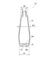
図1に示す容器(化粧品容器)10は、合成樹脂のうち熱可塑性樹脂、例えば、ポリエチレンテレフタレート(PET)やポリシクロへキシレンジメチレンテレフタレート(PCTA、コポリマー)、イーストケミカル社製の「トライタン」(Tritan、コポリエステル)等で形成され、例えば、化粧水や乳液等が収容されるものである。この容器10は、上端に口部11を有するネック部12と、ネック部12から連続する筒状の胴体部13と、胴体部13から連続する底面部14とで構成されている。
A container (cosmetic container) 10 shown in FIG. 1 is made of a thermoplastic resin such as polyethylene terephthalate (PET) or polycyclohexylene dimethylene terephthalate (PCTA, copolymer) among synthetic resins, and “Tritan” (Tritan) manufactured by East Chemical Company. , Copolyester) or the like, and contains, for example, a lotion or an emulsion. The
ここで、容器10は、横断面が略円形の瓶体であり、胴体部13は、底面部14側の端部付近の直径がネック部12側の端部付近の直径よりも大きくなっている。本実施形態では、胴体部13の底面部14側の端部の直径D1がネック部12側の端部の直径D2よりも大きく、また胴体部13は、底面部14側の端部よりも若干上方(ネック部12側)の直径D3が最大径となるように形成されている。
Here, the
また容器10の底面部14は、胴体部13の肉厚よりもかなり厚く形成されている。言い換えれば、胴体部13の肉厚は底面部14に対してかなり薄く形成されており、また均肉化されている。
The
容器10をこのような形状とすることで、例えば、消費者の持つ化粧品容器のイメージに近づけることができる。すなわち、容器10の美観を高めることができるため、容器10を見栄えが重要な化粧品容器等として使用することができる。
By forming the
なお本実施形態では、底面部14の内面、つまり容器10の内底面10aは平坦に形成されている。一方、底面部14の外面、つまり容器10の外底面10bには、内底面10a側に窪ませた凹部15が形成されている。
In the present embodiment, the inner surface of the
このような形状の容器10は、射出成形により形成したプリフォーム20をブロー成形することによって形成する。
The
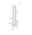
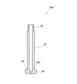
図2に示すように、容器10を形成するためのプリフォーム20は、上端に開口21を有し外周部にねじ溝が形成されたネック部22と、ネック部22に連続する胴部23と、胴部23に連続する底部24とで構成されている。そしてプリフォーム20の底部24は、胴部23よりも大きい直径で形成されている。つまり、プリフォーム20の底部24は、胴部23に対して横方向(外径方向)へフランジ状に膨出した構成になっており、概ねキノコ類の傘に類似した外観形状になっている。
As shown in FIG. 2, a
本発明に係るプリフォーム20は、さらに、このような直径の異なる胴部23と底部24との境界に角部25を備えている。すなわち、胴部23と底部24との境界においてプリフォーム20の直径は、徐々に増加するのではなく急激に増加している。その結果、胴部23と底部24との境界には、胴部23の側面23aと底部24の上面(開口21側の面)24aとで形成される角部25が存在している。また、プリフォーム20の上面視では、角部25は胴部23と底部24との境界において周状(環状)に設けられている。
The
詳しくは後述するが、このような形状のプリフォーム20をブロー成形することにより容器10を所望の形状に形成することができる。すなわち胴部23と底部24との境界に角部25を備えるプリフォーム20を用いて容器10を形成することで、内底面10aを平坦化させた肉厚の底面部14を備える容器10を良好に形成することができる。また、容器10の胴体部13と底面部14との境界付近の内径を所望の大きさまで十分に広げることができる。なお、胴部23の直径に対する底部24の直径の比は1.1から4.0の間で適宜設定することが好ましく、特に、1.2から2.0の範囲に設定するのが望ましい。
As will be described in detail later, the
ここで、角部25の角度θは、略直角であれば多少鈍角であってもよいが、直角(90°)に近い方が好ましい。より具体的には、角部25の角度θは、85°から120°までの範囲、特に、90°から100°までの範囲に設定することが望ましい。これにより、プリフォーム20の範囲をブロー成形する際に、プリフォーム20を適切に延伸させることができ、胴体部13よりも底面部14を肉厚とし内底面10aを平坦状にした容器10を形成し易くなる。なお、容器10の内底面10aを平坦状に形成する必要がないなどの場合には、角部25の角度θを鋭角(例えば、60°から85°の範囲)に設定しても構わない。
Here, the angle θ of the
また本実施形態では、角部25は、プリフォーム20の内底面20aよりも外底面20b側に設けられている。これにより、底部24をより肉厚化し易くなる。勿論、角部25の位置は、この位置に限定されず、内底面20aよりも開口21側であってもよい。
In the present embodiment, the
次に、図3〜図5を参照して、このようなプリフォーム20を用いた容器10の製造方法について説明する。
Next, a method of manufacturing the
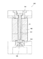
本発明に係る容器10の製造方法は1ステップ式ブロー成形方法(ホットパリソン式ブロー成形方法)によるもので、射出成形工程と、温調工程と、ブロー成形工程とを有する。まずは図3に示すように、射出成形型100を用いてプリフォーム20を射出成形によって形成する(射出成形工程)。プリフォーム20は、上述のようにネック部22、胴部23及び底部24を備えており、射出成形工程では、その全長(縦軸長さ)が容器10の凹部15に対応する部分において容器10の全長よりも若干長くなるように形成する。
The method of manufacturing the
射出成形型100は、例えば、ネック部22の外面を規定する水平方向に開閉可能な割型からなるネック型101と、胴部23の外面を規定する射出キャビティ型102と、底部24の外面を規定する底型103と、プリフォーム20の内面を規定するコア型104と、を備えている。これら射出キャビティ型102、コア型104及び底型103には、図示しない冷却水用の冷却回路が設けられている。
The
なお、本発明のプリフォーム20は底部24が胴部23より大径のフランジ状(アンダーカット状)になっているため、従来のプリフォーム(底部径が胴部径以下の形状)のように、単純にネック型101でプリフォーム20を把持して射出キャビティ型102より上方に引き抜く(離型させる)ことができない。そのため、射出キャビティ型102は、一対の開閉可能な割型から構成されている。また、底型103は、射出キャビティ型102とは独立した単一の金型で構成されている。よって、射出キャビティ型102と底型103の冷却温度を相違させることも可能である。また、底型103とコア型104との間の射出空間は広いため、プリフォーム20の底部24の外表面には、樹脂充填時の痕跡であるシワ(ゲート部を中心とした波形模様)が形成されやすい。よって、コア型104は、射出空間内に充填される樹脂の圧力変動に応じて上下に可動する構造を有しているのが望ましい(詳しくは、特開2013−154622号公報を参照)。
Since the bottom 24 of the
そして、これらネック型101、射出キャビティ型102、底型103及びコア型104とで形成される射出空間内に、底型103の中心部下側のゲート105からPET樹脂等の熱可塑性樹脂を充填することでプリフォーム20を射出成形する。すなわち胴部23と底部24との境界に角部25を備えるプリフォーム20を射出成形により形成する。角部25を設けることで、底部24の外壁面が射出キャビティ型102と底型103との両方に接触可能になる。よって、底部24の冷却効率を従来の手法よりも向上させることができ、底部24の不必要な(成形不良を招きやすい)保有熱を減少させることができる。
Then, a thermoplastic resin such as a PET resin is filled into an injection space formed by the
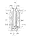
次に、図4に示すように、温調金型としての温調ポット200及び温調コア210を用いてプリフォーム20を所定温度に調整する(温調工程)。具体的には、温調ポット200に底部24の表面(上面24aを除く)を密着させて冷却する。また本実施形態では、温調工程において、プリフォーム20の底部24を冷却するのと同時に、プリフォーム20の胴部23を加熱している。
Next, as shown in FIG. 4, the
温調ポット200は、冷却ブロック201と、2つの加熱ブロック202とを備えている。冷却ブロック201は、所定の温度範囲、例えば、10〜50℃の範囲で温度調整が可能に構成され、プリフォーム20の底部24に沿った内壁面201aを備えている。一方、加熱ブロック202は、所定の温度範囲、例えば、200〜300℃の範囲で温度調整が可能に構成され、プリフォーム20の胴部23の外周面に非接触で対向する内壁面202aを備えている。
The
温調コア210は、プリフォーム20に挿入される棒状の部材であり、その先端部に所定温度に冷却可能な冷却コア部211を備えている。冷却コア部211は、プリフォーム20の内底面20aに沿って形成されている。温調コア210は、冷却コア部211以外の部分は、冷却コア部211よりも細い径で形成され、プリフォーム20の内壁面に対して非接触で挿入されるようになっている。なお、温調コア210の先端は、プリフォーム20の底部24の内底面20aとの接触面積を大きくする目的で内底面20aに沿った形状になっており、好ましくは平坦面状の形状を有している。温調工程の詳細については、本件出願人のWO2013−012067号公報等の公報も参照されたい。
The
そして温調工程では、プリフォーム20が温調ポット200内に配置されると、プリフォーム20の底部24の表面(上面24aを除く)が内壁面201aに密着して部分的に冷却されると共に、プリフォーム20の胴部23が、加熱ブロック202からの輻射熱によって部分的に加熱される。さらに温調コア210がプリフォーム20内に挿入され、冷却コア部211がプリフォーム20の内底面20aに密着し、プリフォーム20が内側からも部分的に冷却される。
In the temperature control step, when the
このような温調工程によりプリフォーム20の温度調整を行うことで、プリフォーム20の温度及び底部24の形状(肉厚)を所望の状態に調整できる。特に、本発明では、プリフォーム20が胴部23と底部24との境界に角部25を備える形状であるため、温調工程において、胴部23と底部24との温度差がより明確になる。したがって、後述するようにブロー成形により容器10を形成する際、プリフォーム20の胴部23を良好に選択的に延伸させることができ、例えば、薄肉状の胴体部13と厚肉状の底面部14の各々の肉厚の分布が整い、かつ、透明度合いや光沢の度合いが均一な状態に維持された容器10を形成することができる。
By adjusting the temperature of the
なお、プリフォームの形状が、例えば、胴部と底部との境界部分(本願の角部25に対応する部分)において外形(直径)が徐々に増加している形状である場合、胴部と底部の境界部分における温度分布にバラツキが生じ易いうえに境界部分の保有熱が高くなり易く、それに伴い、ブロー成形時にプリフォームが偏って延伸する等の不具合が発生し易くなる。具体的には、前述のプリフォーム形状の場合、ブロー成形する際に保有熱が高い境界部分からの破裂や膨出が生じやすく、また、容器にて境界部分に偏った肉だまりが生じやすい。対して、本発明では、角部25を設けているので、効率よく底部24を冷却させたうえに胴部23を加熱させることができ、ブロー成形時にプリフォーム20が偏って延伸する等の不具合が発生し難くなる。
When the shape of the preform is, for example, a shape in which the outer shape (diameter) gradually increases at a boundary portion (a portion corresponding to the
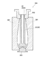
温調工程により温度が調整されたプリフォーム20は、図5に示すようにブロー成形型300内に配置される。ブロー成形型300は、プリフォーム20が内部に収容される一対のブロー割型301と、プリフォーム20のネック部22を保持するネック型302と、プリフォーム20の底部24に対応する上底型303と、を備える。またブロー成形型300は、図示は省略するがネック型302に嵌合して高圧エアを導入するブローコア型を備えている。なおブロー割型301には、冷却媒体が供給される供給路(図示なし)が設けられており、この冷却媒体によってブロー割型301の内部に配置されているプリフォーム20がブローされた後に所定温度にまで冷却されるようになっている。
The
また上底型303は、昇降可能に構成されている。図5に示すように、プリフォーム20がブロー割型301内に配置される際には、上底型303は下降した位置に保持されている。
In addition, the upper
そしてブロー成形工程では、ブロー成形型300に配置されたプリフォーム20内に高圧エアを供給する。その際、プリフォーム20は主に横軸方向に延伸し、図6に示すように、ブロー割型301内壁面に押し付けられる。また高圧エアの供給開始と同時又は若干早めのタイミングで上底型303を上昇させ、プリフォーム20の底部24の圧縮を行う。すなわち上底型303を上昇させることで、容器10の外底面10bに凹部15を形成する。これにより、最終成形品である容器10が成形される。なお、外底面10bの凹部15は必須ではなく、必要に応じて平坦面状にしても構わない。
Then, in the blow molding step, high-pressure air is supplied into the
このような本発明に係る製造方法によりプリフォーム20をブロー成形して容器10を形成することで、所望の形状、例えば、底面部の肉厚が胴体部の肉厚よりも厚い容器10を良好に形成することができる。
By forming the
上述のように本発明に係るプリフォーム20は、胴部23と底部24との境界に角部25を備える形状であり、射出工程や温調工程において、高温の胴部23と低温の底部24との温度差を明確に峻別させることができる構造になっている。このため、ブロー成形工程で、プリフォーム20内に高圧エアを供給すると、プリフォーム20は主に胴部23に相当する部分が横軸方向に延伸されて、容器10が形成される。したがって、プリフォーム20を適切に延伸させることができ、所望の形状、例えば、底面部14の肉厚が胴体部13の肉厚よりも厚い容器10も良好に形成することができる。
As described above, the
なおプリフォーム20の底部24の延伸量は、胴部23の延伸量に比べて少ないため、ブロー成形時、プリフォーム20(胴部23)は角部25で折り込まれるように変形する。その結果、本発明に係る製造方法により形成された容器10には、図7の拡大図に示すように、胴体部13と底面部14との境界付近に、プリフォーム20の胴部23が折り込まれた跡である折り込み部16が全周に亘って連続的に形成される。
Since the amount of extension of the bottom 24 of the
(実施形態2)
図8は、実施形態2に係る容器の一例を示す断面図であり、図9は、実施形態2に係るプリフォームの一例を示す断面図であり、図10は、実施形態2に係る容器の製造方法のブロー成形工程を説明する図である。なお図中同一部材には同一符号を付し、重複する説明は省略する。(Embodiment 2)
FIG. 8 is a cross-sectional view illustrating an example of the container according to the second embodiment, FIG. 9 is a cross-sectional view illustrating an example of the preform according to the second embodiment, and FIG. It is a figure explaining a blow molding process of a manufacturing method. In the drawings, the same members are denoted by the same reference numerals, and overlapping description will be omitted.
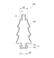
本実施形態は、胴部よりも大きい直径の底部を有するプリフォーム(図2参照)を用いて製造される容器の変形例である。図8に示すように、容器10Aは、上端に口部11を有するネック部12と、ネック部12から連続する所定形状の胴体部13Aとを備えている。胴体部13Aの外形は、下側(底側)に向かって直径が徐々に増加する傘状の三つの部位が上下方向で連続する形状となっている。勿論、胴体部13Aの形状は特に限定されるものではなく、所望の形状に形成すればよい。
The present embodiment is a modified example of a container manufactured using a preform (see FIG. 2) having a bottom part having a diameter larger than that of a body part. As shown in FIG. 8, the
そして本実施形態に係る容器10Aは、胴体部13Aから下方に延びる脚部17をさらに備えている。脚部17は、胴体部13Aのネック部12側の端部の直径(最小径)D2よりも小さい直径D4の小径部17aと、この小径部17aよりも大径の台座部17bとで構成されている。そして、この台座部17bが実施形態1の容器10における底面部14に相当する。つまり容器10Aの台座部17bは、胴体部13Aの肉厚よりもかなり厚く形成されている。言い換えれば、胴体部13Aの肉厚は台座部17bに対してかなり薄く形成されている。なお小径部17aも胴体部13Aの肉厚よりもかなり厚く形成されている。
The
容器10Aをこのような形状とすることで、容器の安定性が向上する。すなわち台座部17bの底面は肉厚で高重量であるため(重心が底面側にあるため)、この台座部17bで安定して容器10Aを接地させることができる。
When the
このような形状の容器10Aは、実施形態1の場合と同様に、射出成形により形成したプリフォームをブロー成形することによって形成する。
The
図9に示すように、容器10Aを形成するためのプリフォーム20Aは、実施形態1と同様に、ネック部22と、胴部23と、底部24とを有し、底部24は、胴部23よりも大きい直径で形成されている。またプリフォーム20Aは、胴部23と底部24との境界に角部25を備えている。
As shown in FIG. 9, a
ここで、実施形態1に係るプリフォーム20では、角部25は、プリフォーム20の内底面20aよりも外底面20b側に設けられていた(図2参照)。一方、実施形態2に係るプリフォーム20Aは、角部25が、内底面20aよりもネック部22側に設けられている。これにより、小径部17aと台座部17bとからなる脚部17を良好にブロー成形することができる。
Here, in the
ところで、本実施形態に係る容器10Aは、基本的には実施形態1と同様の製造方法で製造されるが、次のような点で実施形態1とは相違している。
Incidentally, the
まずは射出成形工程で、上記のようにプリフォーム20Aを射出成形する。その際、角部25が内底面20aよりもネック部22側になるようにする。つまり、プリフォーム20Aの内底面20aの位置がより深い位置となるようにする。これにより、台座部17b(角部25)の冷却効率が上がり、温調時やブロー成形時における台座部17bの外観の変化を抑制することができる。
First, in the injection molding step, the
次いで、実施形態1と同様に温調工程で、プリフォーム20Aを所定温度に加熱する。そして温調工程で所定温度に加熱されたプリフォーム20Aをブロー成形することにより、所望の形状の容器10Aを形成する。ブロー成形工程では、具体的には、図10に示すように、プリフォーム20Aはブロー成形型300A内に配置されてブロー成形される。ブロー成形型300Aは、容器10Aの形状に対応した一対のブロー割型301A及び上底型303Aと、ネック型302とを備えている。ブロー成形型300A内に配置されたプリフォーム20Aは、ブロー割型301Aによって底部24(脚部17に相当する部分)が狭持された状態、つまり底部24(脚部17に相当する部分)の外面が押さえられた状態でブロー成形される。これによりプリフォーム20Aの胴部23が主として横延伸されて、脚部17を備える容器10Aが形成される(図8参照)。なお本実施形態においては、プリフォーム20Aの底部24の下方中央部を僅かながら上方(ネック部12側)に凹ませるように上底型303Aで賦形させている。これにより、容器10Aの台座部17bの下方中央部をその外縁部より上方に位置させることができるため、容器10Aをより安定して接地させることができる。もちろん所望される容器10Aの形状に応じて、台座部17bの下方中央部の外壁面の高さをその外縁部と同じにし、台座部17bの下端面を平坦面状にしても構わない。
Next, the
本実施形態の製造方法では、射出成形工程において、実質的に、容器10Aのネック部12、および脚部17(小径部17a及び台座部17b)を所望の形状に成形(賦形)し、ブロー成形工程では、容器10Aの胴体部13Aのみを所望の形状に成形(賦形)している。このように射出成形工程とブロー成形工程とで、容器10Aの賦形部分を切り分けることで、所望の形状の容器10Aをより良好に形成することができる。
In the manufacturing method of the present embodiment, in the injection molding step, the
以上、本発明の実施形態について説明したが、本発明は、上述の実施形態に限定されるものではない。勿論、本発明は、その主旨を逸脱しない範囲で、種々の変更が可能なものである。 The embodiments of the present invention have been described above, but the present invention is not limited to the above embodiments. Of course, the present invention can be variously modified without departing from the gist thereof.
10,10A 容器
11 口部
12 ネック部
13,13A 胴体部
14 底面部
15 凹部
16 折り込み部
17 脚部
20,20A プリフォーム
21 開口
22 ネック部
23 胴部
24 底部
25 角部
100 射出成形型
101 ネック型
102 射出キャビティ型
103 底型
104 コア型
105 ゲート
200 温調ポット
201 冷却ブロック
202 加熱ブロック
210 温調コア
211 冷却コア部
300,300A ブロー成形型
301,301A ブロー割型
302 ネック型
303,303A 上底型10,
Claims (6)
開口するネック部と、筒状の胴部と、前記胴部よりも大径の底部と、を有し、前記胴部と前記底部との境界に角部を備えており、
前記角部を構成する前記胴部の外周面と前記底部の上面との角度が、直角又は鋭角である
ことを特徴とするプリフォーム。 A preform for forming a container in which the thickness of the bottom portion is thicker than the thickness of the body portion,
An opening neck portion, a cylindrical body portion, and a bottom portion having a larger diameter than the body portion, comprising a corner at a boundary between the body portion and the bottom portion ,
The preform , wherein an angle between an outer peripheral surface of the trunk portion forming the corner portion and an upper surface of the bottom portion is a right angle or an acute angle .
開口するネック部と、筒状の胴部と、前記胴部よりも大径の底部と、を有し、前記胴部と前記底部との境界に角部を備えており、
前記角部が、内底面よりも外底面側に設けられている
ことを特徴とするプリフォーム。 A preform for forming a container in which the thickness of the bottom portion is thicker than the thickness of the body portion,
An opening neck portion, a cylindrical body portion, and a bottom portion having a larger diameter than the body portion, comprising a corner at a boundary between the body portion and the bottom portion,
The preform, wherein the corner is provided on an outer bottom surface side with respect to an inner bottom surface.
開口するネック部と、筒状の胴部と、前記胴部よりも大径の底部と、を有し、前記胴部と前記底部との境界に角部を備え、かつ前記角部を構成する前記胴部の外周面と前記底部の上面との角度が、直角又は鋭角であるプリフォームを、射出成形により形成する射出成形工程と、
少なくとも前記プリフォームの前記底部を温調金型に密着させて冷却し、前記プリフォームの温度を調整する温調工程と、
前記温調工程で温度を調整した前記プリフォームをブロー成形することにより前記容器を形成するブロー成形工程と、を有する
ことを特徴とする容器の製造方法。 In a method of manufacturing a container in which the thickness of the bottom portion is thicker than the thickness of the body portion,
It has an opening neck portion, a cylindrical body portion, and a bottom portion having a larger diameter than the body portion, and has a corner portion at a boundary between the body portion and the bottom portion , and constitutes the corner portion. An angle between the outer peripheral surface of the trunk portion and the upper surface of the bottom portion, a preform having a right angle or an acute angle, an injection molding step of forming by injection molding.
Cooling at least the bottom of the preform in close contact with a temperature control mold, and a temperature control step of adjusting the temperature of the preform,
A blow molding step of forming the container by blow molding the preform whose temperature has been adjusted in the temperature control step.
開口するネック部と、筒状の胴部と、前記胴部よりも大径の底部と、を有し、前記胴部と前記底部との境界に角部を備え、かつ前記角部は内底面よりも外底面側に設けられているプリフォームを、射出成形により形成する射出成形工程と、 An opening neck portion, a cylindrical body portion, and a bottom portion having a larger diameter than the body portion, a corner portion is provided at a boundary between the body portion and the bottom portion, and the corner portion is an inner bottom surface. An injection molding step of forming a preform provided on the outer bottom surface side by injection molding,
少なくとも前記プリフォームの前記底部を温調金型に密着させて冷却し、前記プリフォームの温度を調整する温調工程と、 Cooling at least the bottom of the preform in close contact with a temperature control mold, and a temperature control step of adjusting the temperature of the preform,
前記温調工程で温度を調整した前記プリフォームをブロー成形することにより前記容器を形成するブロー成形工程と、を有する Blow molding step of forming the container by blow molding the preform whose temperature has been adjusted in the temperature control step.
ことを特徴とする容器の製造方法。A method for producing a container, comprising:
前記温調工程では、前記プリフォームの前記底部を冷却しつつ、前記胴部を加熱する
ことを特徴とする容器の製造方法。 The method for producing a container according to claim 3 or 4,
The method of manufacturing a container, wherein in the temperature control step, the body is heated while the bottom of the preform is cooled.
前記ブロー成形工程では、前記容器を、前記胴体部の前記底面部側の端部付近の直径が前記ネック部側の端部付近の直径よりも大きくなるように形成する
ことを特徴とする容器の製造方法。 The method for producing a container according to any one of claims 3 to 5 ,
In the blow molding step, the container may be formed such that a diameter near an end on the bottom portion side of the body portion is larger than a diameter near an end portion on the neck portion side. Production method.
Applications Claiming Priority (5)
| Application Number | Priority Date | Filing Date | Title |
|---|---|---|---|
| JP2015232259 | 2015-11-27 | ||
| JP2015232259 | 2015-11-27 | ||
| JP2016069382 | 2016-03-30 | ||
| JP2016069382 | 2016-03-30 | ||
| PCT/JP2016/085238 WO2017090774A1 (en) | 2015-11-27 | 2016-11-28 | Preform and method of manufacturing vessel |
Publications (2)
| Publication Number | Publication Date |
|---|---|
| JPWO2017090774A1 JPWO2017090774A1 (en) | 2018-10-04 |
| JP6628811B2 true JP6628811B2 (en) | 2020-01-15 |
Family
ID=58764348
Family Applications (1)
| Application Number | Title | Priority Date | Filing Date |
|---|---|---|---|
| JP2017552761A Active JP6628811B2 (en) | 2015-11-27 | 2016-11-28 | Manufacturing method of preform and container |
Country Status (6)
| Country | Link |
|---|---|
| US (1) | US11220023B2 (en) |
| EP (1) | EP3381651B1 (en) |
| JP (1) | JP6628811B2 (en) |
| KR (1) | KR102103758B1 (en) |
| CN (1) | CN108290340B (en) |
| WO (1) | WO2017090774A1 (en) |
Families Citing this family (13)
| Publication number | Priority date | Publication date | Assignee | Title |
|---|---|---|---|---|
| US11135759B2 (en) * | 2017-09-08 | 2021-10-05 | Nissei Asb Machine Co., Ltd. | Blow molding apparatus and blow molding method |
| WO2019118702A2 (en) * | 2017-12-13 | 2019-06-20 | Kent Byron | Method of forming polypropylene bottles |
| WO2019146701A1 (en) * | 2018-01-26 | 2019-08-01 | 日精エー・エス・ビー機械株式会社 | Manufacturing method of a plastic container component, mold unit, and blow molding machine provided with mold unit |
| JP7068930B2 (en) * | 2018-05-31 | 2022-05-17 | 株式会社吉野工業所 | Synthetic resin container and preform |
| KR20210111307A (en) * | 2019-01-31 | 2021-09-10 | 닛세이 에이. 에스. 비 기카이 가부시키가이샤 | Resin container manufacturing apparatus, temperature control apparatus, resin container manufacturing method and temperature control method |
| JP7143505B2 (en) * | 2019-02-21 | 2022-09-28 | 日精エー・エス・ビー機械株式会社 | Manufacturing method of curved neck container |
| US11858194B2 (en) * | 2019-02-28 | 2024-01-02 | Nissei Asb Machine Co., Ltd. | Container mold and method of manufacturing a container |
| WO2020184563A1 (en) | 2019-03-11 | 2020-09-17 | 日精エー・エス・ビー機械株式会社 | Method for producing resin container and apparatus for producing resin container |
| KR102085477B1 (en) * | 2019-04-22 | 2020-03-05 | 필립산업(주) | Vessel for bov |
| WO2021106929A1 (en) * | 2019-11-25 | 2021-06-03 | 日精エー・エス・ビー機械株式会社 | Method and device for manufacturing resin-made container |
| CH716893A1 (en) * | 2019-12-05 | 2021-06-15 | Alpla Werke Alwin Lehner Gmbh & Co Kg | Blow molding tool, stretch blow molding machine and method for forming a container. |
| CN116457181A (en) * | 2020-09-16 | 2023-07-18 | 日精Asb机械株式会社 | Method and apparatus for manufacturing resin container |
| WO2022181627A1 (en) * | 2021-02-25 | 2022-09-01 | 日精エー・エス・ビー機械株式会社 | Temperature regulating mold, and device and method for producing resin container |
Family Cites Families (16)
| Publication number | Priority date | Publication date | Assignee | Title |
|---|---|---|---|---|
| NL264149A (en) * | 1960-05-02 | 1900-01-01 | ||
| FR2261117B1 (en) * | 1974-02-14 | 1976-11-26 | Solvay | |
| JPS55107430A (en) * | 1979-02-09 | 1980-08-18 | Yoshino Kogyosho Co Ltd | Forming method of bottle with handle made of plastic |
| US4649004A (en) | 1983-12-27 | 1987-03-10 | Toyo Seikan Kaisha, Ltd. | Process for production of multi-layer pipes for draw-forming |
| JPS60137610A (en) * | 1983-12-27 | 1985-07-22 | Toyo Seikan Kaisha Ltd | Molding process of multilayer pipe for bottle |
| US4785948A (en) * | 1987-02-03 | 1988-11-22 | Herbert Strassheimer | Blow molded plastic container having a reinforced wall structure and preform therefor |
| JPH0649327B2 (en) * | 1989-07-20 | 1994-06-29 | 日精エー・エス・ビー機械株式会社 | Injection stretch blow molding method |
| JP4687855B2 (en) * | 2001-06-29 | 2011-05-25 | 株式会社青木固研究所 | Preform for small flat container and small flat container |
| ITMO20060037A1 (en) | 2006-02-03 | 2007-08-04 | Sacmi | PREFORM TO OBTAIN CONTAINERS AND ITS CONTAINER |
| JP5463716B2 (en) * | 2009-04-10 | 2014-04-09 | 東洋製罐株式会社 | Preform compression mold, synthetic resin blow molding container manufacturing method, and preform |
| US9034446B2 (en) * | 2010-02-26 | 2015-05-19 | Husky Injection Molding Systems Ltd. | Preform suitable for blow-molding into a final shaped container |
| JP5721031B2 (en) * | 2011-06-30 | 2015-05-20 | 株式会社吉野工業所 | Synthetic resin casing and molding method thereof |
| KR101961185B1 (en) * | 2011-07-20 | 2019-03-22 | 닛세이 에이. 에스. 비 기카이 가부시키가이샤 | Temperature control apparatus for preforms, temperature control method for preforms, resin container and method for producing resin container |
| WO2013089054A1 (en) * | 2011-12-13 | 2013-06-20 | 吉田プラ工業株式会社 | Parison and container blow-molding method using same |
| JP5888731B2 (en) | 2012-01-31 | 2016-03-22 | 日精エー・エス・ビー機械株式会社 | Mold apparatus, injection molding apparatus and injection molding method |
| KR20130089054A (en) | 2012-02-01 | 2013-08-09 | 박주흠 | Method for providing user-oriented application |
-
2016
- 2016-11-28 US US15/779,476 patent/US11220023B2/en active Active
- 2016-11-28 WO PCT/JP2016/085238 patent/WO2017090774A1/en not_active Ceased
- 2016-11-28 CN CN201680069263.5A patent/CN108290340B/en active Active
- 2016-11-28 JP JP2017552761A patent/JP6628811B2/en active Active
- 2016-11-28 KR KR1020187017299A patent/KR102103758B1/en active Active
- 2016-11-28 EP EP16868717.6A patent/EP3381651B1/en active Active
Also Published As
| Publication number | Publication date |
|---|---|
| CN108290340A (en) | 2018-07-17 |
| KR102103758B1 (en) | 2020-04-23 |
| CN108290340B (en) | 2020-05-22 |
| JPWO2017090774A1 (en) | 2018-10-04 |
| US11220023B2 (en) | 2022-01-11 |
| EP3381651B1 (en) | 2021-04-28 |
| EP3381651A4 (en) | 2019-07-24 |
| US20180257264A1 (en) | 2018-09-13 |
| EP3381651A1 (en) | 2018-10-03 |
| WO2017090774A1 (en) | 2017-06-01 |
| KR20180083924A (en) | 2018-07-23 |
Similar Documents
| Publication | Publication Date | Title |
|---|---|---|
| JP6628811B2 (en) | Manufacturing method of preform and container | |
| JP6230173B2 (en) | Blow molding method for resin containers | |
| KR102178400B1 (en) | Mold for molding and mold for injection molding | |
| US20090078672A1 (en) | Container and Preform for Obtaining a Container | |
| CN105189085B (en) | Model with Offset Parting Surfaces for Manufacturing Enhanced Stability Vessels | |
| WO2019146701A1 (en) | Manufacturing method of a plastic container component, mold unit, and blow molding machine provided with mold unit | |
| EP2948284B1 (en) | Preform of plastic material with lightened closed end | |
| US12454091B2 (en) | Method and apparatus for producing resin container | |
| JP6340047B2 (en) | Preform for plastic bottles | |
| US20220402189A1 (en) | Method and device for manufacturing resin-made container | |
| JP7846913B2 (en) | Injection stretch blow molding method and temperature-controlled rod | |
| KR101804423B1 (en) | Apparatus for manufacturing of container | |
| US20120112390A1 (en) | Stretch rod for a two-stage blow molding machine | |
| KR20020008092A (en) | Manufacture process of heatproof pet bottle and preform manufactured therewith and heatproof pet bottle |
Legal Events
| Date | Code | Title | Description |
|---|---|---|---|
| A621 | Written request for application examination |
Free format text: JAPANESE INTERMEDIATE CODE: A621 Effective date: 20180522 |
|
| RD02 | Notification of acceptance of power of attorney |
Free format text: JAPANESE INTERMEDIATE CODE: A7422 Effective date: 20190426 |
|
| A521 | Request for written amendment filed |
Free format text: JAPANESE INTERMEDIATE CODE: A821 Effective date: 20190517 |
|
| RD04 | Notification of resignation of power of attorney |
Free format text: JAPANESE INTERMEDIATE CODE: A7424 Effective date: 20190517 |
|
| A131 | Notification of reasons for refusal |
Free format text: JAPANESE INTERMEDIATE CODE: A131 Effective date: 20190702 |
|
| A521 | Request for written amendment filed |
Free format text: JAPANESE INTERMEDIATE CODE: A523 Effective date: 20190826 |
|
| TRDD | Decision of grant or rejection written | ||
| A01 | Written decision to grant a patent or to grant a registration (utility model) |
Free format text: JAPANESE INTERMEDIATE CODE: A01 Effective date: 20191119 |
|
| A61 | First payment of annual fees (during grant procedure) |
Free format text: JAPANESE INTERMEDIATE CODE: A61 Effective date: 20191203 |
|
| R150 | Certificate of patent or registration of utility model |
Ref document number: 6628811 Country of ref document: JP Free format text: JAPANESE INTERMEDIATE CODE: R150 |
|
| R250 | Receipt of annual fees |
Free format text: JAPANESE INTERMEDIATE CODE: R250 |
|
| R250 | Receipt of annual fees |
Free format text: JAPANESE INTERMEDIATE CODE: R250 |
|
| R250 | Receipt of annual fees |
Free format text: JAPANESE INTERMEDIATE CODE: R250 |
|
| R250 | Receipt of annual fees |
Free format text: JAPANESE INTERMEDIATE CODE: R250 |