JP6627931B2 - Vehicle seat - Google Patents
Vehicle seat Download PDFInfo
- Publication number
- JP6627931B2 JP6627931B2 JP2018150804A JP2018150804A JP6627931B2 JP 6627931 B2 JP6627931 B2 JP 6627931B2 JP 2018150804 A JP2018150804 A JP 2018150804A JP 2018150804 A JP2018150804 A JP 2018150804A JP 6627931 B2 JP6627931 B2 JP 6627931B2
- Authority
- JP
- Japan
- Prior art keywords
- pair
- frame
- right direction
- support member
- main body
- Prior art date
- Legal status (The legal status is an assumption and is not a legal conclusion. Google has not performed a legal analysis and makes no representation as to the accuracy of the status listed.)
- Active
Links
- 239000002184 metal Substances 0.000 claims description 15
- 230000001105 regulatory effect Effects 0.000 claims description 15
- 239000011347 resin Substances 0.000 claims description 15
- 229920005989 resin Polymers 0.000 claims description 15
- 238000006073 displacement reaction Methods 0.000 description 2
- 239000000463 material Substances 0.000 description 2
- 230000003014 reinforcing effect Effects 0.000 description 2
- JOYRKODLDBILNP-UHFFFAOYSA-N Ethyl urethane Chemical compound CCOC(N)=O JOYRKODLDBILNP-UHFFFAOYSA-N 0.000 description 1
- 210000001217 buttock Anatomy 0.000 description 1
- 230000007797 corrosion Effects 0.000 description 1
- 238000005260 corrosion Methods 0.000 description 1
- 238000010586 diagram Methods 0.000 description 1
- 239000004744 fabric Substances 0.000 description 1
- 239000006260 foam Substances 0.000 description 1
- JEIPFZHSYJVQDO-UHFFFAOYSA-N iron(III) oxide Inorganic materials O=[Fe]O[Fe]=O JEIPFZHSYJVQDO-UHFFFAOYSA-N 0.000 description 1
- 239000010985 leather Substances 0.000 description 1
- 238000004519 manufacturing process Methods 0.000 description 1
- 230000002265 prevention Effects 0.000 description 1
- 238000003466 welding Methods 0.000 description 1
Images


Description
本発明は、乗員を支持する支持部材を備える乗物用シートに関する。 The present invention relates to a vehicle seat including a support member for supporting an occupant.
枠状のクッションフレームを有し、クッションフレームのフロントフレームとリアフレームに乗員を支持する支持部材としてのSバネを架け渡したシートクッションが知られている(特許文献1)。このシートクッションは、Sばねが左右にずれないように、リアフレームを構成する連結シャフトを加工して溝を形成し、この溝にSバネの端部が掛止されたリテーナを係合させている。 2. Description of the Related Art A seat cushion having a frame-shaped cushion frame and having an S spring as a support member for supporting an occupant mounted on a front frame and a rear frame of the cushion frame is known (Patent Document 1). This seat cushion forms a groove by processing the connecting shaft constituting the rear frame so that the S spring does not shift to the left and right, and engages the retainer with the end of the S spring engaged with this groove. I have.
しかしながら、特許文献1のように、リアフレームを加工すると大幅にコストが上昇するという問題がある。 However, as in Patent Document 1, there is a problem that processing the rear frame significantly increases the cost.
そこで、本発明は、簡易な構造で支持部材のずれを抑制することができる乗物用シートを提供することを目的とする。
また、本発明は、音の発生を抑制することを目的とする。
Therefore, an object of the present invention is to provide a vehicle seat that can suppress displacement of a support member with a simple structure.
Another object of the present invention is to suppress generation of sound.
前記した目的を達成するため、本発明の乗物用シートは、左右に離間して配置された一対のサイドフレームと、互いに離間して配置され、一対のサイドフレームを連結する一対の連結フレームと、一対の連結フレームの間に配置された本体部、及び、本体部から延び一対の連結フレームに掛止された掛止部を有し、一対の連結フレームに架設された、乗員を支持する支持部材と、サイドフレームを覆うカバー部材とを備える。
そして、本体部は、カバー部材に当接することで、支持部材の左右方向の位置を規制する規制部を有することを特徴とする。
In order to achieve the above-described object, the vehicle seat of the present invention includes a pair of side frames arranged to be separated from each other left and right, and a pair of connection frames arranged to be separated from each other and connecting the pair of side frames, A support member having a main body disposed between the pair of connection frames, and a hook extending from the main body and hooked on the pair of connection frames, and supported by the pair of connection frames, supporting the occupant. And a cover member that covers the side frame.
The main body portion has a regulating portion that regulates the position of the support member in the left-right direction by contacting the cover member.
このような構成によれば、支持部材の本体部に設けられた規制部をカバー部材に当接させることで、支持部材の左右方向の位置を規制することができるので、簡易な構造で支持部材のずれを抑制することができる。このため、乗物用シートのコストの上昇を抑えることができる。 According to such a configuration, the position of the support member in the left-right direction can be regulated by bringing the regulation portion provided on the main body of the support member into contact with the cover member, so that the support member has a simple structure. Deviation can be suppressed. Therefore, an increase in the cost of the vehicle seat can be suppressed.
前記した乗物用シートにおいて、カバー部材は、サイドフレームの左右方向内側に配置される内壁部を有する構成とすることができる。
この場合、規制部は、内壁部に左右方向外側から当接するように構成されていてもよい。
また、規制部は、内壁部に左右方向内側から当接するように構成されていてもよい。
In the vehicle seat described above, the cover member may be configured to have an inner wall portion that is disposed inside the left and right sides of the side frame.
In this case, the restricting portion may be configured to abut on the inner wall portion from the outside in the left-right direction.
Further, the restricting portion may be configured to contact the inner wall portion from the inner side in the left-right direction.
前記した乗物用シートにおいて、カバー部材は、サイドフレームの連結フレームが連結された部分の周囲を覆っている構成とすることができる。 In the vehicle seat described above, the cover member may be configured to cover a periphery of a portion where the connection frame of the side frame is connected.
この場合、カバー部材は、連結フレームに沿って左右方向内側に延びる延出部を有していてもよい。そして、掛止部は、延出部に接触しない構成とすることができる。 In this case, the cover member may have an extension that extends inward in the left-right direction along the connection frame. And the latch part can be set as the structure which does not contact an extension part.
前記した乗物用シートにおいて、カバー部材は、樹脂からなることが望ましい。 In the vehicle seat described above, the cover member is desirably made of resin.
このように、カバー部材が樹脂で構成されていることで、規制部がカバー部材に当接しているときの音の発生を抑制することができる。 As described above, since the cover member is made of the resin, it is possible to suppress the generation of a sound when the restricting portion is in contact with the cover member.
前記した乗物用シートにおいて、支持部材は、金属線材と、金属線材の少なくとも一部を被覆した樹脂部材とを含んで構成することができる。この場合、規制部は、樹脂部材により構成されていることが望ましい。 In the vehicle seat described above, the support member may include a metal wire and a resin member that covers at least a part of the metal wire. In this case, it is desirable that the restricting portion is formed of a resin member.
このように、規制部が樹脂部材により構成されていることで、規制部がカバー部材に当接しているときの音の発生を抑制することができる。 As described above, since the restricting portion is formed of the resin member, it is possible to suppress the generation of sound when the restricting portion is in contact with the cover member.
本発明によれば、簡易な構造で乗員を支持する支持部材のずれを抑制することができる。 ADVANTAGE OF THE INVENTION According to this invention, the displacement of the support member which supports an occupant can be suppressed with a simple structure.
また、本発明によれば、音の発生を抑制することができる。 Further, according to the present invention, generation of sound can be suppressed.
[第1実施形態]
以下、添付の図面を参照しながら、発明の実施形態について説明する。なお、本明細書において、前後、左右、上下は、シートに座った乗員を基準とする。また、左右方向の内側および外側は、車両ではなくシートを基準とする。
図1に示すように、本実施形態の乗物用シートは、自動車の運転席や助手席などで使用される車両用シートSとして構成されており、主に、シートクッションS1と、シートバックS2とを備えている。
[First Embodiment]
Hereinafter, embodiments of the invention will be described with reference to the accompanying drawings. In addition, in this specification, front and rear, left and right, and up and down are based on the occupant sitting on the seat. The inside and outside in the left-right direction are based on the seat, not the vehicle.
As shown in FIG. 1, the vehicle seat according to the present embodiment is configured as a vehicle seat S used in a driver's seat or a passenger seat of an automobile, and mainly includes a seat cushion S1 and a seat back S2. It has.
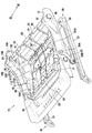
シートクッションS1の内部には、シートクッションS1のフレームを構成する、図2に示すようなクッションフレームF1が内蔵されている。シートクッションS1は、クッションフレームF1に、ウレタンフォームなどからなるパッドと、布地や皮革などからなる表皮材を被せることで構成されている。また、図示は省略するが、シートバックS2は、シートバックS2のフレームを構成するバックフレームに、パッドと、表皮材を被せることで構成されている。 Inside the seat cushion S1, a cushion frame F1 as shown in FIG. 2, which constitutes a frame of the seat cushion S1, is incorporated. The seat cushion S1 is configured by covering a pad made of urethane foam or the like and a skin material made of cloth, leather, or the like on the cushion frame F1. Although not shown, the seat back S2 is configured by covering a back frame constituting a frame of the seat back S2 with a pad and a skin material.
クッションフレームF1は、一対のサイドフレーム10と、一対の連結フレームの一例としてのフロントフレーム21およびリアフレーム22と、パンフレーム23と、カバー部材100とを備えている。
サイドフレーム10は、左右に離間して一対配置されている。
フロントフレーム21とリアフレーム22は、互いに前後に離間して配置されている。
フロントフレーム21は、円形断面の金属パイプからなり、一対のサイドフレーム10の前部同士を連結している。
リアフレーム22は、円形断面の金属パイプからなり、一対のサイドフレーム10の後部同士を連結している。
パンフレーム23は、金属板からなるフレームであり、フロントフレーム21よりも前の位置で一対のサイドフレーム10の前部同士を連結している。
The cushion frame F1 includes a pair of
The
The
The
The
The
クッションフレームF1は、スライドレール機構30に、ハイト調整機構を介して支持されている。
スライドレール機構30は、前後方向に長く延び、左右に離間して配置された一対のロアレール31と、各ロアレール31に対して前後にスライド可能に係合して設けられた一対のアッパーレール32とからなる。ロアレール31は、図示しない車両のフロアに固定される。
The cushion frame F1 is supported by the
The
ハイト調整機構は、一対のフロントリンク35と、一対のリアリンク36とを含んでなる。
フロントリンク35は、上端部がピン35Aによってサイドフレーム10の前部に回動可能に連結され、下端部がピン35Bによってアッパーレール32の前部に回動可能に連結されている。
リアリンク36は、上端部がサイドフレーム10に回動可能に連結されている。また、リアリンク36は、下端部が、アッパーレール32の後部に図示しないピンにより回動可能に連結されている。
The height adjusting mechanism includes a pair of
The
The upper end of the
フロントリンク35およびリアリンク36は、アッパーレール32およびサイドフレーム10とともに4節リンクを構成している。そして、図示しない電動または手動のアクチュエータによりフロントリンク35またはリアリンク36をサイドフレーム10に対して回動させることにより、サイドフレーム10の高さを変えることができるようになっている。
The
リアフレーム22は、円筒状のブラケット81を介してサイドフレーム10に連結されている。ブラケット81は、左右内側の端部が、リアフレーム22の外側に嵌まり、溶接部によりリアフレーム22に溶接されている。また、ブラケット81は、左右外側の端部が、サイドフレーム10から外れないように、サイドフレーム10に回動可能に支持されている。これにより、リアフレーム22は、サイドフレーム10から外れないようにサイドフレーム10に組み付けられ、サイドフレーム10によって回動可能に支持されている。
The
前記したリアリンク36は、ブラケット81に挿通されており、ブラケット81に溶接されている。これにより、リアリンク36は、ブラケット81およびリアフレーム22と一体に回動可能となっている。
The above-described
カバー部材100は、樹脂からなり、サイドフレーム10の後部を覆っている。なお、カバー部材100は、左右のサイドフレーム10それぞれに設けられているが、図2においては、右側のカバー部材100のみを図示し、左側のカバー部材100は省略している。
The
カバー部材100は、サイドフレーム10の上面を覆う上壁部110と、上壁部110から左右方向内側へ延びる傾斜部120と、傾斜部120から下方へ延びる第1内壁部130と、傾斜部120の後側で上壁部110から下方へ延びる第2内壁部140とを有している。
The
傾斜部120は、リアフレーム22より前側に設けられている。傾斜部120は、図3に示すように、左右方向内側に向かうにつれて下方に位置するように延びている。
第1内壁部130は、内壁部の一例であり、サイドフレーム10およびリアリンク36の左右方向内側に配置されている。
The
The first
図2に戻り、第2内壁部140は、サイドフレーム10のリアフレーム22が連結された部分の周囲を覆っている。第2内壁部140は、リアフレーム22に沿って左右方向内側へ延びる延出部150を有している。具体的に、延出部150は、第2内壁部140から左右方向内側へ突出する壁であり、リアリンク36の後端に沿った円弧形状を有している。
Returning to FIG. 2, the second
一対のサイドフレーム10の間には、乗員を支持する支持部材50が配置されている。支持部材50は、図示しないシートクッションS1のパッドの下に位置し、シートクッションS1のパッドを下から、つまり、乗員とは反対側から支持する。
支持部材50は、一対の連結フレームの間に配置された乗員を支持する部分である本体部51と、本体部51から延びて一対の連結フレームに掛止される掛止部として、フロントフレーム21に掛止される掛止部52とリアフレーム22に掛止される掛止部53とを有している。各掛止部52,53は、フロントフレーム21およびリアフレーム22の外形に倣った半円断面のフック形状を有している。
掛止部52がフロントフレーム21に掛止され、掛止部53がリアフレーム22に掛止されることで、支持部材50は、フロントフレーム21およびリアフレーム22に架設されている。
A
The
The
支持部材50は、複数の金属線材61と、金属線材61の少なくとも一部を被覆した樹脂部材62とを含んでなる。本実施形態においては、樹脂部材62は、金属線材61の全体を被覆している。このため、金属線材61に高い防錆処理をしなくても、樹脂部材62により金属線材61の腐食を抑制することができる。
The
リアフレーム22に掛止された掛止部53は、左右に分かれて3つ設けられている。左右の掛止部53は、延出部150等のカバー部材100の各部分から離れた位置に配置されている。
The three hooking
本体部51は、後部の左右に、左右方向外側に向かうにつれて上方へ延びる羽部51Aと、羽部51Aの下で左右方向外側へ延びる延長部51Bと、延長部51Bから上方へ延びる規制部51Cとを有している。
The
羽部51Aは、カバー部材100の傾斜部120とともに、乗員の臀部の側部を支持する。
図3に示すように、羽部51Aは、上端部が、第1内壁部130の上端に対し、左右方向内側に離れた位置に設けられている。また、羽部51Aは、傾斜部120から離れており、傾斜部120が羽部51Aの動きを規制しないようになっている。
羽部51Aと延長部51Bの間には、羽部51Aと延長部51Bを繋ぐ補強部51Dが形成されている。このように、補強部51Dが設けられていることで、羽部51Aが補強されている。
The
As shown in FIG. 3, the upper end portion of the
Between the
規制部51Cは、カバー部材100の第1内壁部130の左右方向外側に配置され、第1内壁部130に隣接している。そして、右側の規制部51Cは、支持部材50が左の方に移動しようとした場合に第1内壁部130に右側、つまり、左右方向外側から当接することで、支持部材50の左右方向の位置を規制する。規制部51Cは、樹脂部材62により構成されている。図示は省略するが、左側の規制部51Cも左のカバー部材100の第1内壁部130の左右方向外側に配置され、支持部材50が右の方に移動しようとした場合に第1内壁部130に左側、つまり、左右方向外側から当接する。
The restricting
なお、図3においては、規制部51Cが第1内壁部130に当接した状態を示しているが、支持部材50のクッションフレームF1への組付を容易にするために、通常時は規制部51Cと第1内壁部130の間に多少の遊びがあるのがよい。もっとも、規制部51Cにより支持部材50の左右方向の位置規制が可能となるように、左右の規制部51Cと第1内壁部130との遊びは小さく、例えば10mm以下に設定されている。また、規制部51Cと第1内壁部130との遊びは、カバー部材100の延出部150と支持部材50の掛止部53の距離よりも小さく、支持部材50が左右に移動しても、掛止部53が延出部150に接触しないようになっている。
FIG. 3 shows a state in which the restricting
以上のように構成された車両用シートSによれば、乗員がシートクッションS1に繰り返し座ったことや、着座中に横方向への力が繰り返し掛かったことにより支持部材50が左右方向にずれた場合、右または左の規制部51Cがカバー部材100の第1内壁部130に当接することで支持部材50がそれ以上動くことが規制される。カバー部材100は、乗物用シートに通常設けられている部材であるので、本実施形態によれば、製造コストの上昇を抑えつつ、簡易な構造で支持部材50のずれを抑制することができる。
According to the vehicle seat S configured as described above, the occupant is repeatedly seated on the seat cushion S1, and the
そして、規制部51Cが第1内壁部130に当接しているときに、支持部材50に乗員からの荷重が掛かると、第1内壁部130と規制部51Cが擦れてきしみ音が発生する可能性があるが、規制部51Cが樹脂部材62により構成され、また、第1内壁部130が樹脂からなることで、この音の発生を抑制することができる。
When a load from an occupant is applied to the
[第2実施形態]
次に、本発明の第2実施形態について説明する。第2実施形態に係る乗物用シートは、第1実施形態に対して支持部材50の構成が一部異なるだけであるので、この異なる部分のみについて説明する。
[Second embodiment]
Next, a second embodiment of the present invention will be described. The vehicle seat according to the second embodiment differs from the first embodiment only in part of the configuration of the
図4に示すように、第2実施形態においては、支持部材50の規制部51Cは、カバー部材100の第1内壁部130に、左右方向外側から当接するのではなく、左右方向内側から当接するように構成されている。具体的に、規制部51Cは、第1内壁部130の左右方向内側に配置され、第1内壁部130に隣接している。右側の規制部51Cは、支持部材50が右の方に移動しようとした場合に、第1内壁部130に左側から当接することで支持部材50の左右方向の位置を規制する。左側の規制部51Cは、支持部材50が左の方に移動しようとした場合に、第1内壁部130に右側から当接することで支持部材50の左右方向の位置を規制する。
As shown in FIG. 4, in the second embodiment, the restricting
このように構成された構成された車両用シートSによっても、第1実施形態と同様に支持部材50の位置を規制することができる。
With the vehicle seat S configured as described above, the position of the
以上に本発明の一実施形態について説明したが、本発明は前記実施形態に限定されるものではない。具体的な構成については、下記のように発明の趣旨を逸脱しない範囲で適宜変更が可能である。 Although one embodiment of the present invention has been described above, the present invention is not limited to the embodiment. The specific configuration can be appropriately changed without departing from the spirit of the invention as described below.
第2実施形態において、羽部51Aとは別に設けられた規制部51Cが第1内壁部130に左右方向内側から当接するように構成されていたが、羽部51Aを第1内壁部130に左右方向内側から当接するように構成してもよい。すなわち、羽部51Aが、カバー部材100に当接することで支持部材50の左右方向の位置を規制する規制部であってもよい。
In the second embodiment, the restricting
第1実施形態において、本体部51の左右に規制部51Cが設けられ、この規制部51Cがそれぞれカバー部材100の第1内壁部130に左右方向外側から当接する場合を説明したが、本体部51の左右の一方に、第1内壁部130を挟むように設けられた一対の規制部を設け、この一対の規制部が、第1内壁部130に左右方向内側と外側から当接する構成であってもよい。また、左右の一方のみに本発明の規制部を設け、この規制部がカバー部材100に当接する構成とし、左右の他方は、本発明とは異なる他の位置規制の構造を採用してもよい。
In the first embodiment, a case has been described in which the regulating
前記実施形態において、支持部材50がクッションフレームF1に配置される構成を説明したが、支持部材は、シートバックフレームに配置することもできる。この場合においても、シートバックフレームに対して支持部材を上下方向に架設して、支持部材の本体部を、サイドフレームを覆うカバー部材に当接させることで支持部材を位置規制することが可能である。
In the above embodiment, the configuration in which the
また、前記実施形態では、乗物用シートとして自動車に搭載される車両用シートSを例示したが、乗物用シートは、これに限定されず、自動車以外の乗物、例えば、鉄道車両や船舶、航空機などに搭載されるシートであってもよい。 Further, in the above-described embodiment, the vehicle seat S mounted on an automobile is exemplified as the vehicle seat, but the vehicle seat is not limited to this, and vehicles other than automobiles, for example, railway vehicles, ships, aircraft, etc. It may be a seat mounted on a vehicle.
また、前記した実施形態および変形例で説明した各要素を、任意に組み合わせて実施することも可能である。 Further, the components described in the above-described embodiment and modified examples may be arbitrarily combined and implemented.
10 サイドフレーム
21 フロントフレーム
22 リアフレーム
50 支持部材
51 本体部
51C 規制部
52 掛止部
53 掛止部
61 金属線材
62 樹脂部材
100 カバー部材
130 第1内壁部
150 延出部
S 車両用シート
DESCRIPTION OF
Claims (7)
互いに離間して配置され、前記一対のサイドフレームを連結する一対の連結フレームと、
前記一対の連結フレームの間に配置され、かつ前記一対の連結フレームに接触しない本体部、及び、前記本体部から延び前記一対の連結フレームに接触して掛止された掛止部を有し、前記一対の連結フレームに架設された、乗員を支持する支持部材と、
前記サイドフレームを覆うカバー部材とを備え、
前記本体部は、左右方向の端部から上方に延びる規制部を有し、
前記規制部は、前記掛止部の上端よりも下の位置で前記カバー部材に当接することで、前記支持部材の左右方向の位置を規制することを特徴とする乗物用シート。 A pair of side frames arranged left and right apart,
A pair of connecting frames arranged apart from each other and connecting the pair of side frames,
A main body portion disposed between the pair of connection frames and not in contact with the pair of connection frames, and a hook portion extending from the main body portion and being hooked in contact with the pair of connection frames, A support member erected on the pair of connection frames and supporting an occupant,
A cover member that covers the side frame,
The main body has a restricting portion extending upward from an end in the left-right direction,
The restricting portion than said upper retainers that abuts against the cover member at a position below the support vehicle seat characterized that you regulating the lateral position of the member.
前記規制部は、前記羽部よりも左右方向外側で前記カバー部材に当接することで、前記支持部材の左右方向の位置を規制することを特徴とする請求項1に記載の乗物用シート。 2. The vehicle seat according to claim 1, wherein the restricting portion restricts the position of the support member in the left-right direction by abutting the cover member on the outer side in the left-right direction with respect to the wing portion. 3.
前記規制部は、前記羽部の上端よりも下の位置で前記カバー部材に当接することで、前記支持部材の左右方向の位置を規制することを特徴とする請求項1に記載の乗物用シート。 2. The vehicle seat according to claim 1, wherein the restricting portion restricts the position of the support member in the left-right direction by contacting the cover member at a position lower than an upper end of the wing portion. 3. .
前記規制部は、前記金属線材の前記樹脂部材で被覆された部分よりも左右外側に位置することを特徴とする請求項1から請求項4のいずれか1項に記載の乗物用シート。 The vehicle seat according to any one of claims 1 to 4, wherein the restricting portion is located on the left and right outer sides of a portion of the metal wire covered with the resin member.
前記シートクッションは、シートクッションフレームを含み、 The seat cushion includes a seat cushion frame,
前記シートクッションは、 The seat cushion,
左右に離間して配置された一対のサイドフレームと、 A pair of side frames arranged left and right apart,
互いに離間して配置され、前記一対のサイドフレームを連結する一対の連結フレームと、 A pair of connecting frames arranged apart from each other and connecting the pair of side frames,
前記一対の連結フレームの間に配置され、かつ前記一対の連結フレームに接触しない本体部、及び、前記本体部から延び前記一対の連結フレームに接触して掛止された掛止部を有し、前記一対の連結フレームに架設された、乗員を支持する支持部材と、 A main body portion disposed between the pair of connection frames and not in contact with the pair of connection frames, and a hook portion extending from the main body portion and being hooked in contact with the pair of connection frames, A support member erected on the pair of connection frames and supporting an occupant,
前記サイドフレームを覆うカバー部材とを備え、 A cover member that covers the side frame,
前記連結フレームは、前記一対のサイドフレームの後部同士を連結するリアフレームと、前記一対のサイドフレームの前部同士を連結するフロントフレームとを含み、 The connection frame includes a rear frame that connects rear portions of the pair of side frames, and a front frame that connects front portions of the pair of side frames,
前記シートクッションフレームは、前記フロントフレームよりも前の位置で前記一対のサイドフレームの前部同士を連結する金属板からなるパンフレームを有し、 The seat cushion frame has a pan frame made of a metal plate that connects front portions of the pair of side frames at a position before the front frame,
前記本体部は、左右方向の端部から上方に延びる規制部を有し、 The main body has a restricting portion extending upward from an end in the left-right direction,
前記規制部は、前記掛止部の上端よりも下の位置で前記カバー部材に当接することで、前記支持部材の左右方向の位置を規制することを特徴とする乗物用シート。 The vehicle seat according to claim 1, wherein the restricting portion restricts the position of the support member in the left-right direction by abutting on the cover member at a position lower than an upper end of the hooking portion.
Priority Applications (1)
| Application Number | Priority Date | Filing Date | Title |
|---|---|---|---|
| JP2018150804A JP6627931B2 (en) | 2018-08-09 | 2018-08-09 | Vehicle seat |
Applications Claiming Priority (1)
| Application Number | Priority Date | Filing Date | Title |
|---|---|---|---|
| JP2018150804A JP6627931B2 (en) | 2018-08-09 | 2018-08-09 | Vehicle seat |
Related Parent Applications (1)
| Application Number | Title | Priority Date | Filing Date |
|---|---|---|---|
| JP2017058881A Division JP6386612B1 (en) | 2017-03-24 | 2017-03-24 | Vehicle seat |
Related Child Applications (1)
| Application Number | Title | Priority Date | Filing Date |
|---|---|---|---|
| JP2019219209A Division JP6860801B2 (en) | 2019-12-04 | 2019-12-04 | Vehicle seat |
Publications (3)
| Publication Number | Publication Date |
|---|---|
| JP2018167838A JP2018167838A (en) | 2018-11-01 |
| JP2018167838A5 JP2018167838A5 (en) | 2019-06-27 |
| JP6627931B2 true JP6627931B2 (en) | 2020-01-08 |
Family
ID=64019755
Family Applications (1)
| Application Number | Title | Priority Date | Filing Date |
|---|---|---|---|
| JP2018150804A Active JP6627931B2 (en) | 2018-08-09 | 2018-08-09 | Vehicle seat |
Country Status (1)
| Country | Link |
|---|---|
| JP (1) | JP6627931B2 (en) |
Families Citing this family (1)
| Publication number | Priority date | Publication date | Assignee | Title |
|---|---|---|---|---|
| JP7202203B2 (en) * | 2019-02-01 | 2023-01-11 | テイ・エス テック株式会社 | vehicle seat |
Family Cites Families (4)
| Publication number | Priority date | Publication date | Assignee | Title |
|---|---|---|---|---|
| JP4066359B2 (en) * | 2003-07-11 | 2008-03-26 | スズキ株式会社 | Sensor cover structure of seat |
| JP2015221599A (en) * | 2014-05-22 | 2015-12-10 | トヨタ自動車株式会社 | Vehicle seat |
| JP2016117406A (en) * | 2014-12-22 | 2016-06-30 | ダイハツ工業株式会社 | Seat cushion pad support structure |
| US9718387B2 (en) * | 2015-08-03 | 2017-08-01 | Ford Global Technologies, Llc | Seat cushion module for a vehicle seating assembly |
-
2018
- 2018-08-09 JP JP2018150804A patent/JP6627931B2/en active Active
Also Published As
| Publication number | Publication date |
|---|---|
| JP2018167838A (en) | 2018-11-01 |
Similar Documents
| Publication | Publication Date | Title |
|---|---|---|
| WO2018173336A1 (en) | Vehicle seat | |
| JP6050097B2 (en) | Vehicle seat | |
| JP6386611B1 (en) | Vehicle seat | |
| JP6386612B1 (en) | Vehicle seat | |
| JP6627931B2 (en) | Vehicle seat | |
| US9663009B2 (en) | Conveyance seat | |
| JP2023054332A (en) | vehicle seat | |
| JP6346334B1 (en) | Vehicle seat | |
| JP2014100941A (en) | Vehicle seat | |
| JP7132533B2 (en) | vehicle seat | |
| JP6495358B2 (en) | Vehicle seat | |
| JP6860801B2 (en) | Vehicle seat | |
| JP5989856B2 (en) | Vehicle seat | |
| JP6054713B2 (en) | Vehicle seat | |
| JP6053465B2 (en) | Vehicle seat | |
| JP2021183493A5 (en) | ||
| JP6551574B2 (en) | Vehicle seat | |
| JP7161099B2 (en) | vehicle seat | |
| JP2013193568A (en) | Vehicle seat | |
| JP6513726B2 (en) | Vehicle seat | |
| JP6412228B2 (en) | Vehicle seat | |
| JP6366672B2 (en) | Vehicle seat | |
| JP2017114425A (en) | Seat frame structure | |
| JP6200036B2 (en) | Vehicle seat | |
| JP2017001496A (en) | Vehicle seat |
Legal Events
| Date | Code | Title | Description |
|---|---|---|---|
| A521 | Request for written amendment filed |
Free format text: JAPANESE INTERMEDIATE CODE: A523 Effective date: 20190521 |
|
| A621 | Written request for application examination |
Free format text: JAPANESE INTERMEDIATE CODE: A621 Effective date: 20190521 |
|
| A871 | Explanation of circumstances concerning accelerated examination |
Free format text: JAPANESE INTERMEDIATE CODE: A871 Effective date: 20190613 |
|
| A975 | Report on accelerated examination |
Free format text: JAPANESE INTERMEDIATE CODE: A971005 Effective date: 20190716 |
|
| TRDD | Decision of grant or rejection written | ||
| A01 | Written decision to grant a patent or to grant a registration (utility model) |
Free format text: JAPANESE INTERMEDIATE CODE: A01 Effective date: 20191105 |
|
| A977 | Report on retrieval |
Free format text: JAPANESE INTERMEDIATE CODE: A971007 Effective date: 20191031 |
|
| A61 | First payment of annual fees (during grant procedure) |
Free format text: JAPANESE INTERMEDIATE CODE: A61 Effective date: 20191118 |
|
| R150 | Certificate of patent or registration of utility model |
Ref document number: 6627931 Country of ref document: JP Free format text: JAPANESE INTERMEDIATE CODE: R150 |
|
| R250 | Receipt of annual fees |
Free format text: JAPANESE INTERMEDIATE CODE: R250 |
|
| R250 | Receipt of annual fees |
Free format text: JAPANESE INTERMEDIATE CODE: R250 |