JP6627329B2 - Recording device - Google Patents

Recording device Download PDF

Info

Publication number
JP6627329B2
JP6627329B2 JP2015164506A JP2015164506A JP6627329B2 JP 6627329 B2 JP6627329 B2 JP 6627329B2 JP 2015164506 A JP2015164506 A JP 2015164506A JP 2015164506 A JP2015164506 A JP 2015164506A JP 6627329 B2 JP6627329 B2 JP 6627329B2
Authority
JP
Japan
Prior art keywords
end side
hole
medium
liquid ejection
recording unit
Prior art date
Legal status (The legal status is an assumption and is not a legal conclusion. Google has not performed a legal analysis and makes no representation as to the accuracy of the status listed.)
Active
Application number
JP2015164506A
Other languages
Japanese (ja)
Other versions
JP2016107622A (en
JP2016107622A5 (en
Inventor
小高 俊和
俊和 小高
亨 丹生
亨 丹生
Current Assignee (The listed assignees may be inaccurate. Google has not performed a legal analysis and makes no representation or warranty as to the accuracy of the list.)
Seiko Epson Corp
Original Assignee
Seiko Epson Corp
Priority date (The priority date is an assumption and is not a legal conclusion. Google has not performed a legal analysis and makes no representation as to the accuracy of the date listed.)
Filing date
Publication date
Application filed by Seiko Epson Corp filed Critical Seiko Epson Corp
Priority to US14/946,342 priority Critical patent/US9527695B2/en
Publication of JP2016107622A publication Critical patent/JP2016107622A/en
Priority to US15/352,179 priority patent/US9724941B2/en
Publication of JP2016107622A5 publication Critical patent/JP2016107622A5/ja
Application granted granted Critical
Publication of JP6627329B2 publication Critical patent/JP6627329B2/en
Active legal-status Critical Current
Anticipated expiration legal-status Critical

Links

Images

Description

本発明は、記録装置に関する。   The present invention relates to a recording device.

従来から、記録装置の一種として、ライン型のヘッド(記録部)から用紙等の媒体に対してインクを噴射することにより印刷(記録)を行うインクジェット式プリンターが知られている(例えば、特許文献1参照)。このようなプリンターは、排紙部を上面に有した上筐体が下筐体に対して水平方向に延びる軸線を中心として回動可能に構成された装置筐体を備えている。   2. Description of the Related Art Conventionally, as one type of recording apparatus, an ink jet printer that performs printing (recording) by ejecting ink from a line-type head (recording unit) onto a medium such as paper has been known (for example, Patent Document 1). 1). Such a printer includes an apparatus housing in which an upper housing having a paper discharge unit on the upper surface is rotatable about an axis extending in a horizontal direction with respect to a lower housing.

すなわち、上筐体は、下筐体に近接した近接位置と、下筐体から離隔した離隔位置との間で回動可能に構成されている。そして、プリンターは、上筐体にライン型のヘッドが搭載されているため、上筐体が離隔位置に回動された際に形成される正面側の開口から上筐体のヘッドにアクセスしてヘッドのメンテナンスができるようになっている。   That is, the upper housing is configured to be rotatable between a proximity position close to the lower housing and a separated position separated from the lower housing. Then, since the printer has a line-type head mounted on the upper housing, the printer accesses the head of the upper housing from an opening on the front side formed when the upper housing is rotated to the separated position. The head can be maintained.

また、このようなプリンターにおいては、用紙の搬送方向と直交する幅方向に対して記録部が傾くことによって、用紙に正しく画像が印刷されない現象が発生し、印刷された画像の品質が低下してしまうことがある。   Further, in such a printer, a phenomenon occurs in which an image is not printed correctly on a sheet due to a tilt of a recording unit with respect to a width direction orthogonal to a sheet conveying direction, and the quality of a printed image is reduced. Sometimes.

特に、用紙の搬送方向と直交する幅方向に渡って同時にインクを吐出可能なプリンターでは、記録部として、複数のノズルからなるノズル列が用紙の幅方向に沿って複数配設された液体吐出ヘッドを備える構成が採用される場合がある。この場合、液体吐出ヘッドの各ノズル列は、用紙の搬送方向においてオフセットされた所謂千鳥状に配置されることによって、記録部は、用紙の幅方向においてノズルが等間隔で連続するように構成されている。   In particular, in a printer capable of simultaneously ejecting ink in a width direction orthogonal to the sheet conveyance direction, a liquid ejection head in which a plurality of nozzle rows including a plurality of nozzles are arranged along the sheet width direction as a recording unit. May be adopted. In this case, the nozzle rows of the liquid ejection head are arranged in a so-called zigzag manner offset in the sheet conveyance direction, so that the recording unit is configured such that the nozzles are continuous at equal intervals in the sheet width direction. ing.

このような複数のノズル列を有する液体吐出ヘッドを備える記録部の場合、記録面の面方向において用紙の幅方向に対して記録部が傾くことによって、用紙の幅方向において隣り合うノズル列間の距離が、用紙の搬送方向から見て変化する。このため、用紙の幅方向におけるノズルの間隔はノズル列間において異なる間隔となる。この結果、幅方向において等間隔でない状態となったノズルから吐出されたインクによって印刷された画像は品質が低下してしまうことになる。   In the case of a recording section including a liquid ejection head having such a plurality of nozzle rows, the recording section is inclined with respect to the width direction of the sheet in the plane direction of the recording surface, so that the nozzle section adjacent to the nozzle row in the sheet width direction is formed. The distance changes when viewed from the paper transport direction. For this reason, the intervals between the nozzles in the width direction of the paper are different between the nozzle rows. As a result, the quality of an image printed with ink ejected from nozzles that are not at equal intervals in the width direction will be degraded.

そのために、搬送される用紙の幅方向に対する記録部の傾き、すなわち液体吐出ヘッドの傾きを調節することが必要である。そして、この液体吐出ヘッドの傾きの調節方法として、図25のように従来、液体吐出ヘッド1201〜1210を有し、付勢部材(引張りコイルスプリング1232)によって引っ張られているヘッド基体1002(記録部)を、カム1027(偏心カム)に接触させつつ付勢部材の付勢力に抗して基準ピン1002Pを中心に回転させる構成が提案されている。すなわち、カム1027とヘッド基体1002(記録部)の外縁とを付勢部材により当接させることによって、ヘッド基体1002(記録部)を位置決めしつつ、ヘッド基体1002(記録部)の位置ずれを相殺する角度分回転させる方法が提案されている(例えば、特許文献2参照)。   Therefore, it is necessary to adjust the inclination of the recording unit with respect to the width direction of the conveyed sheet, that is, the inclination of the liquid ejection head. As a method of adjusting the inclination of the liquid discharge head, as shown in FIG. 25, a head base 1002 (recording unit) which conventionally has liquid discharge heads 1201 to 1210 and is pulled by an urging member (tension coil spring 1232) is used. ) Is rotated around the reference pin 1002P against the urging force of the urging member while contacting the cam 1027 (eccentric cam). That is, the cam 1027 and the outer edge of the head base 1002 (recording section) are brought into contact with each other by the urging member, so that the head base 1002 (recording section) is positioned and the displacement of the head base 1002 (recording section) is offset. There has been proposed a method of rotating by an angle (see, for example, Patent Document 2).

特開2013−136242号公報JP 2013-136242 A 特開2010−228434号公報JP 2010-228434 A

しかしながら、従来技術(図25)のように、カム1027が複数の液体吐出ヘッド1201〜1210を有するヘッド基体1002(記録部)の外縁に接触しつつ、付勢部材の付勢力に抗してヘッド基体1002(記録部)を押し付けながら回転する構成とした場合、少なくともカム1027の部分を配置するためのスペースが必要となる。このため、ヘッド基体1002(記録部)として大型化してしまう虞がある。   However, as in the prior art (FIG. 25), the cam 1027 contacts the outer edge of the head base 1002 (recording unit) having the plurality of liquid ejection heads 1201 to 1210, and resists the urging force of the urging member. When the configuration is such that the base 1002 (recording unit) rotates while being pressed, a space for arranging at least the cam 1027 is required. For this reason, there is a possibility that the size of the head base 1002 (recording unit) becomes large.

加えて、カムと液体吐出ヘッドの外縁との少なくとも一方が、カムの回転によって摩耗することが付勢部材の付勢力により促進される。このために、液体吐出ヘッドをカムの回転によって位置ずれが相殺される角度分まで回転させることができなくなる虞もある。   In addition, at least one of the cam and the outer edge of the liquid ejection head is worn by the rotation of the cam, and is accelerated by the urging force of the urging member. For this reason, there is a possibility that the liquid ejection head cannot be rotated to the angle at which the displacement is offset by the rotation of the cam.

また、液体吐出ヘッドが付勢部材によって付勢されて位置決めされる構成の場合は、例えば、用紙が高速で搬送される際に生じる振動等により液体吐出ヘッドを付勢している付勢部材が振動し、液体吐出ヘッドが回転方向において振動することが起こり得る。その結果、液体吐出ヘッドの振動のために記録品質の低下を招く虞もある。   In the case of a configuration in which the liquid ejection head is biased and positioned by the biasing member, for example, the biasing member that biases the liquid discharge head by vibration or the like generated when the sheet is conveyed at a high speed is used. Vibration may cause the liquid ejection head to vibrate in the rotational direction. As a result, the recording quality may be degraded due to the vibration of the liquid ejection head.

また、上述のようなプリンターでは、ヘッドが上筐体に取り付けられている。すなわち、ヘッドによって印刷が行われる媒体が搬送される下筐体とは異なる上筐体にヘッドが設けられている。このため、印刷精度を確保するべく上筐体の下筐体に対するヒンジの精度を確保する必要があるが、ヒンジの精度を確保することは困難であるため、場合によってはヘッドの位置精度が確保できなくなってしまうという問題がある。   In the printer as described above, the head is mounted on the upper housing. That is, the head is provided in an upper housing different from the lower housing in which a medium on which printing is performed by the head is transported. For this reason, it is necessary to ensure the accuracy of the hinge with respect to the lower housing of the upper housing in order to ensure the printing accuracy, but it is difficult to ensure the accuracy of the hinge, and in some cases, the positioning accuracy of the head is ensured. There is a problem that it will not be possible.

本発明は、このような従来技術に存在する問題点に着目してなされたものである。その目的とするところは、記録部の位置精度を確保しつつ、記録部のメンテナンス作業を容易に行うことができる記録装置を提供することにある。また、記録部の傾き補正を行うための機構を配置するスペースを省スペース化して、大型化を抑制することができる記録装置を提供することにある。   The present invention has been made in view of such problems existing in the conventional technology. It is an object of the present invention to provide a recording apparatus capable of easily performing a maintenance operation on a recording unit while securing the positional accuracy of the recording unit. Another object of the present invention is to provide a recording apparatus capable of saving a space for disposing a mechanism for correcting a tilt of a recording unit and suppressing an increase in size.

以下、上記課題を解決するための手段及びその作用効果について記載する。
上記課題を解決する記録装置は、搬送経路に沿って搬送される媒体に記録を行うライン型の記録部と、前記記録部を収容する収容ユニットと、前記記録部によって記録された前記媒体を排出する排出部と、前記記録部の上方に位置し、前記排出部によって排出された前記媒体を受けて支持し、前記収容ユニットに対して開閉可能な支持部と、を備え、前記支持部を開放動作させることにより、前記記録部に対して上方からアクセス可能なアクセス経路が形成される。
Hereinafter, means for solving the above-described problems and the effects thereof will be described.
A recording apparatus that solves the above-described problem includes a line-type recording unit that performs recording on a medium that is transported along a transport path, an accommodation unit that accommodates the recording unit, and discharges the medium recorded by the recording unit. A discharge unit, which is located above the recording unit, receives and supports the medium discharged by the discharge unit, and is openable and closable with respect to the storage unit. By operating, an access path accessible from above to the recording unit is formed.

この構成によれば、支持部を開放動作させることで、記録部に対して上方からアクセス可能なアクセス経路が形成される。加えて、支持部を開放動作しても記録部が移動することはない。したがって、記録部の位置精度を確保しつつ、記録部のメンテナンス作業を容易に行うことが可能となる。   According to this configuration, an access path accessible from above to the recording unit is formed by opening the support unit. In addition, the recording unit does not move even when the support unit is opened. Therefore, it is possible to easily perform the maintenance work of the recording unit while securing the positional accuracy of the recording unit.

上記記録装置において、前記支持部は、上から見たときの前記記録部との重なり部分が、閉じた状態よりも少なくなるまで開くことが可能に構成されていることが好ましい。
この構成によれば、記録部に対して上方からアクセスし易くすることが可能となる。
In the recording apparatus, it is preferable that the support unit is configured to be able to be opened until an overlapping portion with the recording unit when viewed from above becomes smaller than a closed state.
According to this configuration, it is possible to easily access the recording unit from above.

上記課題を解決する記録装置は、搬送経路に沿って搬送される媒体に記録を行うライン型の記録部と、前記記録部を収容する収容ユニットと、前記記録部によって記録された前記媒体を排出する排出部と、前記記録部の上方に位置し、前記排出部によって排出された前記媒体を受けて支持し、前記収容ユニットに対して開閉可能な支持部と、前記支持部と前記記録部との間に配置されて前記媒体を反転させる反転経路を形成する経路形成部材と、を備え、前記支持部を開いた状態で前記経路形成部材を開放動作させることにより、前記記録部に対して上方からアクセス可能なアクセス経路が形成される。   A recording apparatus that solves the above-described problem includes a line-type recording unit that performs recording on a medium that is transported along a transport path, an accommodation unit that accommodates the recording unit, and discharges the medium recorded by the recording unit. A discharge unit that is located above the recording unit, receives and supports the medium discharged by the discharge unit, and is capable of opening and closing the storage unit; and the support unit and the recording unit. A path forming member that is disposed between the recording medium and the path forming member to form a reversing path for reversing the medium. An access route accessible from is formed.

この構成によれば、支持部を開いた状態で経路形成部材を開放動作させることで、記録部に対して上方からアクセス可能なアクセス経路が形成される。加えて、支持部及び経路形成部材を開放動作しても記録部が移動することはない。したがって、記録部の位置精度を確保しつつ、記録部のメンテナンス作業を容易に行うことが可能となる。   According to this configuration, by opening the path forming member with the support section opened, an access path accessible from above to the recording section is formed. In addition, the recording unit does not move even when the support unit and the path forming member are opened. Therefore, it is possible to easily perform the maintenance work of the recording unit while securing the positional accuracy of the recording unit.

上記記録装置において、前記経路形成部材は、前記媒体が排出される排出方向に向かうほど高さが高くなるように傾斜しており、前記経路形成部材が開閉動作する際の開閉支点は、前記排出方向の上流側に位置していることが好ましい。
この構成によれば、経路形成部材を容易に開くことが可能となる。
In the recording apparatus, the path forming member is inclined so as to increase in height in a discharge direction in which the medium is discharged. It is preferably located upstream in the direction.
According to this configuration, the path forming member can be easily opened.

上記記録装置において、前記経路形成部材は、前記収容ユニットに対して着脱可能に構成されていることが好ましい。
この構成によれば、経路形成部材を収容ユニットから取り外すことで、記録部に対してより一層上方からアクセスし易くすることが可能となる。
In the recording apparatus, it is preferable that the path forming member is configured to be detachable from the storage unit.
According to this configuration, the recording section can be more easily accessed from above by removing the path forming member from the storage unit.

上記記録装置において、前記支持部は、前記媒体が排出される排出方向に向かうほど高さが高くなるように傾斜しており、前記支持部が開閉動作する際の開閉支点は、前記排出方向の上流側に位置していることが好ましい。
この構成によれば、支持部を容易に開くことが可能となる。
In the recording apparatus, the support portion is inclined so as to increase in height in a discharge direction in which the medium is discharged, and an opening / closing fulcrum when the support portion opens and closes moves in the discharge direction. It is preferably located upstream.
According to this configuration, the support portion can be easily opened.

上記記録装置において、前記支持部は、前記収容ユニットに対して着脱可能に構成されていることが好ましい。
この構成によれば、支持部を収容ユニットから取り外すことで、記録部に対してより一層上方からアクセスし易くすることが可能となる。
In the recording apparatus, it is preferable that the support unit is configured to be detachable from the storage unit.
According to this configuration, by removing the support unit from the storage unit, it is possible to more easily access the recording unit from above.

上記記録装置において、前記記録部には、前記搬送経路における前記媒体の搬送方向及び当該媒体の記録面の法線に沿う方向の双方と交差する方向を長手方向とし、当該長手方向における一方の端部に前記法線に沿う方向に貫通する一端側貫通孔と、前記長手方向における他方の端部に前記法線に沿う方向に貫通する他端側貫通孔とが設けられ、前記収容ユニットには、前記法線に沿う方向の軸線を有し、前記一端側貫通孔に挿入される一端側挿入軸と、前記法線に沿う方向の軸線を有し、前記他端側貫通孔に挿入される他端側挿入軸と、を設けた基台部が備えられ、前記一端側貫通孔は円形孔であって、前記一端側挿入軸は、前記基台部に固定された一端側固定軸であり、前記他端側貫通孔は前記記録部の前記長手方向に沿う平行縁部を有する長孔であって、前記他端側挿入軸は、前記基台部に固定された他端側固定軸であることが好ましい。   In the recording apparatus, the recording unit may include, as a longitudinal direction, a direction intersecting both a conveying direction of the medium in the conveying path and a direction along a normal to a recording surface of the medium, and one end in the longitudinal direction. The part is provided with one end side through hole penetrating in the direction along the normal line, and the other end in the longitudinal direction is provided with another end side through hole penetrating in the direction along the normal line, and the housing unit is , Having an axis in a direction along the normal line, having one end insertion shaft inserted into the one end side through hole, and having an axis in a direction along the normal line, and inserted into the other end side through hole. A base portion provided with the other end side insertion shaft, the one end side through hole is a circular hole, and the one end side insertion shaft is one end side fixed shaft fixed to the base portion. The other end side through-hole has a parallel edge portion along the longitudinal direction of the recording portion. That a long hole, the other end side insertion axis, it is preferable that the a fixed end side fixed shaft to the base unit.

この構成によれば、記録部は、一端側挿入軸および他端側挿入軸によって搬送方向および長手方向への移動が抑制されて位置決めされる。   According to this configuration, the recording unit is positioned while being prevented from moving in the transport direction and the longitudinal direction by the one end insertion shaft and the other end insertion shaft.

上記記録装置において、前記他端側挿入軸は、前記他端側固定軸の中心軸線から偏心した軸線を中心軸とする円筒面を外面に有し、当該円筒面が前記他端側固定軸を中心に回動可能な偏心円筒部材を備えることが好ましい。   In the recording apparatus, the other end side insertion shaft has a cylindrical surface having an axis eccentric from a center axis of the other end side fixed shaft on an outer surface, and the cylindrical surface corresponds to the other end side fixed shaft. It is preferable to provide an eccentric cylindrical member rotatable at the center.

この構成によれば、偏心円筒部材を回転させることによって、搬送方向と交差する方向に対する記録部の長手方向の傾きが調節される。   According to this configuration, by rotating the eccentric cylindrical member, the inclination of the recording unit in the longitudinal direction with respect to the direction intersecting the transport direction is adjusted.

上記記録装置において、前記記録部は、前記長手方向に併設された複数の液体吐出ヘッドを含んで構成され、前記他端側貫通孔は、前記複数の液体吐出ヘッドの内、最も前記他方の端部の側にある液体吐出ヘッドと、前記記録部の前記媒体の前記搬送方向において重なるように配置されていることが好ましい。   In the above recording apparatus, the recording unit is configured to include a plurality of liquid ejection heads provided in parallel in the longitudinal direction, and the other end side through hole is the other end of the plurality of liquid ejection heads. It is preferable that the recording unit and the liquid ejection head on the side of the unit are arranged so as to overlap in the transport direction of the medium in the recording unit.

この構成によれば、記録部の外形を長手方向や短手方向へ延ばしてその形状を大きくすることなく、記録部を位置決めするための他端側貫通孔を形成することが可能である。すなわち、記録部の外形寸法を省スペース化して記録装置の大型化を抑制することができる。   According to this configuration, it is possible to form the other end side through-hole for positioning the recording unit without extending the outer shape of the recording unit in the longitudinal direction or the lateral direction and enlarging the shape. That is, it is possible to save the external dimensions of the recording unit and to suppress the enlargement of the recording apparatus.

上記記録装置において、前記一端側貫通孔は、前記複数の液体吐出ヘッドの内、最も前記一方の端部の側にある液体吐出ヘッドと、前記記録部の前記媒体の前記搬送方向において重なるように配置されていることが好ましい。   In the recording apparatus, the one end side through-hole may overlap with the liquid ejection head closest to the one end of the plurality of liquid ejection heads in the recording unit in the transport direction of the medium. Preferably, they are arranged.

この構成によれば、記録部の外形を長手方向や短手方向へ延ばしてその形状を大きくすることなく、記録部を位置決めするための一端側貫通孔を形成することが可能である。すなわち、記録部の外形寸法を省スペース化して記録装置の大型化を抑制することができる。   According to this configuration, it is possible to form the one end side through hole for positioning the recording unit without extending the outer shape of the recording unit in the longitudinal direction or the lateral direction and enlarging the shape. That is, it is possible to save the external dimensions of the recording unit and to suppress the enlargement of the recording apparatus.

上記記録装置において、前記記録部を前記媒体の前記記録面に対して相対的に移動させる移動部を備え、前記一端側挿入軸及び前記他端側挿入軸は、前記移動部が前記記録部を移動させる際に前記記録部の移動を案内する案内軸であることが好ましい。   In the recording apparatus, the recording apparatus further includes a moving unit that relatively moves the recording unit with respect to the recording surface of the medium, wherein the one end side insertion shaft and the other end side insertion shaft are configured such that the moving unit has the recording unit. It is preferable that a guide shaft guides the movement of the recording unit when moving.

この構成によれば、記録部を媒体の記録面に対して相対的に移動させる際の案内軸を別途設ける必要がないので、記録装置の構造が複雑化することを抑制することができる。   According to this configuration, there is no need to separately provide a guide shaft for moving the recording unit relative to the recording surface of the medium, so that the structure of the recording apparatus can be prevented from becoming complicated.

上記記録装置において、前記一端側挿入軸が挿入される前記一端側貫通孔を第1貫通孔としたとき、前記記録部は、前記移動部によって移動させられる移動方向において、前記第1貫通孔よりも前記媒体の前記記録面から遠い位置に設けられ、前記一端側挿入軸が挿入される第2貫通孔を備え、前記第2貫通孔は前記記録部の長手方向に沿う平行縁部を有する長孔であることが好ましい。   In the recording apparatus, when the one end side through hole into which the one end side insertion shaft is inserted is a first through hole, the recording unit is moved from the first through hole in a moving direction moved by the moving unit. A second through-hole provided at a position remote from the recording surface of the medium and into which the one-end-side insertion shaft is inserted, wherein the second through-hole has a parallel edge along a longitudinal direction of the recording unit. It is preferably a hole.

この構成によれば、記録部を媒体の記録面に対して平行となるように調節する場合、移動方向への記録部の移動量が長手方向の両端部において異なる場合であっても、一端側挿入軸が長孔の第2貫通孔において抉られることなく円滑に移動することができる。   According to this configuration, when the recording unit is adjusted so as to be parallel to the recording surface of the medium, even if the amount of movement of the recording unit in the moving direction is different at both ends in the longitudinal direction, one end side The insertion shaft can move smoothly without being dug in the second through hole of the long hole.

記録装置の斜視図。FIG. 2 is a perspective view of a recording device. 記録装置の模式構造図。FIG. 2 is a schematic structural diagram of a recording device. 記録装置における載置台とその周辺の側断面図。FIG. 4 is a side sectional view of a mounting table and its periphery in the recording apparatus. 記録装置における載置台が開放位置にあるときの状態を示す正面図。FIG. 3 is a front view illustrating a state where the mounting table in the recording apparatus is at an open position. 記録装置においてプリンター部からスキャナー部、自動給紙装置、及び操作部を取り外して載置台を開けたときの状態を示す要部拡大斜視図。FIG. 4 is an enlarged perspective view of a main part showing a state where the scanner unit, the automatic paper feeder, and the operation unit are removed from the printer unit and the mounting table is opened in the recording apparatus. 図5において経路形成部材を開けたときの状態を示す要部拡大斜視図。The principal part expansion perspective view which shows the state at the time of opening a path | route formation member in FIG. 図6において経路形成部材を取り外したときの状態を示す要部拡大斜視図。FIG. 7 is an enlarged perspective view of a main part showing a state when a path forming member is removed in FIG. 6. 図7において記録部を取り出すときの状態を示す要部拡大斜視図。FIG. 8 is an enlarged perspective view of a main part showing a state when the recording unit is taken out in FIG. 7. 記録部がプリンター部に取り付けられているときの状態を示す要部模式側面図。FIG. 4 is a schematic side view of a main part showing a state when the recording unit is attached to the printer unit. 図9においてプリンター部から締結板を取り外したときの状態を示す要部模式側面図。FIG. 10 is a schematic side view of a main part showing a state when the fastening plate is removed from the printer unit in FIG. 9. 図10においてプリンター部から記録部を取り外したときの状態を示す要部模式側面図。The principal part schematic side view which shows the state at the time of removing the recording part from the printer part in FIG. 実施形態2に係る記録装置を模式的に示す構造図。FIG. 4 is a structural diagram schematically showing a recording device according to a second embodiment. 記録部に対して支持台とキャップとを入れ替える入替機構の模式図。FIG. 4 is a schematic diagram of a replacement mechanism that replaces a support table and a cap with respect to a recording unit. 記録部を媒体の記録面に対して相対移動させる軸受移動機構の斜視図。FIG. 3 is a perspective view of a bearing moving mechanism that moves a recording unit relatively to a recording surface of a medium. キャップが記録部の臨む空間を覆う状態を示す模式図。FIG. 3 is a schematic diagram illustrating a state in which a cap covers a space facing a recording unit. キャップが記録部に対して位置決めされる構造を示す斜視構造図。FIG. 3 is a perspective view illustrating a structure in which a cap is positioned with respect to a recording unit. キャップが記録部に対して位置決めされた状態を示す側面図。FIG. 4 is a side view showing a state where the cap is positioned with respect to the recording unit. 記録部を液体吐出ヘッド側から見た斜視図。FIG. 3 is a perspective view of a recording unit as viewed from a liquid ejection head side. 媒体の搬送部と記録部を位置決めする挿入軸とが設けられた基台部の構成を示す斜視図。FIG. 3 is a perspective view showing a configuration of a base unit provided with a medium transport unit and an insertion shaft for positioning a recording unit. 偏心円筒部材の斜視図。FIG. 3 is a perspective view of an eccentric cylindrical member. 偏心円筒部材を円筒面の中心軸の軸線方向から見た平面図。The top view which looked at the eccentric cylindrical member from the axial direction of the central axis of a cylindrical surface. 記録部の傾きを調節する調節動作を模式的に示す説明図。FIG. 7 is an explanatory diagram schematically showing an adjustment operation for adjusting the inclination of the recording unit. 記録部の傾きを調節する調節動作を模式的に示す説明図。FIG. 7 is an explanatory diagram schematically showing an adjustment operation for adjusting the inclination of the recording unit. 記録部を媒体の記録面と平行に調節する調節動作を模式的に示す説明図。FIG. 4 is an explanatory diagram schematically illustrating an adjustment operation of adjusting a recording unit in parallel with a recording surface of a medium. 記録部を媒体の記録面と平行に調節する調節動作を模式的に示す説明図。FIG. 4 is an explanatory diagram schematically illustrating an adjustment operation of adjusting a recording unit in parallel with a recording surface of a medium. キャップの記録部に対する位置決め構造の変形例を模式的に示す斜視図。FIG. 9 is a perspective view schematically showing a modification of the positioning structure of the cap with respect to the recording unit. 位置決め構造を下方から見た平面図。The top view which looked at the positioning structure from the lower part. 記録部における貫通孔の配置を模式的に示す説明図。FIG. 4 is an explanatory diagram schematically showing the arrangement of through holes in a recording unit. 記録部における貫通孔の配置を模式的に示す説明図。FIG. 4 is an explanatory diagram schematically showing the arrangement of through holes in a recording unit. 記録部における貫通孔の配置を模式的に示す説明図。FIG. 4 is an explanatory diagram schematically showing the arrangement of through holes in a recording unit. 記録部における貫通孔の配置を模式的に示す説明図。FIG. 4 is an explanatory diagram schematically showing the arrangement of through holes in a recording unit. 従来の記録部における傾き補正機構の配置を模式的に示す説明図。FIG. 9 is an explanatory diagram schematically showing the arrangement of a tilt correction mechanism in a conventional recording unit. 反転経路を備えない記録装置を模式的に示す構造図。FIG. 3 is a structural diagram schematically showing a recording apparatus having no inversion path.

(実施形態1)
以下、記録装置の一実施形態を、図面に従って説明する。
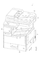
図1に示すように、記録装置11は、全体として鉛直方向Zに長い略直方体状をなしており、収容ユニットの一例としてのプリンター部12と、プリンター部12上に配置されたスキャナー部13と、スキャナー部13上に配置された自動給紙装置14とを備えている。プリンター部12上におけるスキャナー部13の隣には、記録装置11の各種の操作を行うための操作部15が設けられている。
(Embodiment 1)
Hereinafter, an embodiment of a recording apparatus will be described with reference to the drawings.
As shown in FIG. 1, the recording device 11 has a substantially rectangular parallelepiped shape that is long in the vertical direction Z as a whole, and includes a printer unit 12 as an example of an accommodation unit, and a scanner unit 13 arranged on the printer unit 12. , An automatic paper feeder 14 arranged on the scanner unit 13. An operation unit 15 for performing various operations of the recording device 11 is provided next to the scanner unit 13 on the printer unit 12.

図2に示すように、プリンター部12内には、媒体の一例としての用紙Pが搬送される搬送経路の一例としての媒体搬送路20と、複数のローラー(ローラー対)によって構成されるとともに用紙Pを媒体搬送路20に沿って搬送する搬送部21とが備えられている。また、プリンター部12内には、用紙Pを鉛直方向Zの下側から支持する支持台22と、支持台22に支持された用紙Pに画像を印刷(記録)するライン型の記録部23とが収容されている。   As shown in FIG. 2, the printer unit 12 includes a medium transport path 20 as an example of a transport path on which a sheet P as an example of a medium is transported, and a plurality of rollers (roller pairs). A transport unit 21 that transports P along the medium transport path 20 is provided. The printer unit 12 includes a support table 22 for supporting the sheet P from below the vertical direction Z, and a line-type recording unit 23 for printing (recording) an image on the sheet P supported by the support table 22. Is housed.

プリンター部12は、図2における紙面と直交する方向を用紙Pの幅方向Xとし、この幅方向Xと交差する方向を搬送方向として用紙Pを支持台22上及び媒体搬送路20に沿って搬送する。記録部23は、用紙Pの搬送方向と交差する幅方向Xの略全域に渡ってインクを同時に噴射可能な液体吐出ヘッドとしてのラインヘッドを下部に備え、支持台22上を搬送される用紙Pに対して鉛直方向Zの上側からインクを噴射して付着させることによって画像を印刷する。   The printer unit 12 transports the paper P on the support table 22 and the medium transport path 20 with the direction orthogonal to the paper surface in FIG. 2 as the width direction X of the paper P and the direction intersecting the width direction X as the transport direction. I do. The recording unit 23 includes a line head as a liquid ejection head capable of simultaneously ejecting ink over substantially the entire area in the width direction X intersecting with the conveyance direction of the paper P, and includes a line head as a liquid ejection head. An image is printed by ejecting and attaching ink from above in the vertical direction Z.

印刷された用紙Pは、排紙ローラー対24や他の複数の搬送ローラー対25によって記録部23から媒体搬送路20に搬送され、媒体搬送路20の下流側の端部に設けられた排出部の一例としての媒体排出口26から排出される。媒体排出口26から排出された用紙Pは、落下して記録部23の鉛直方向Zの上側に配置された支持部の一例としての載置台27上に、図2において二点鎖線で示すように積層状態で載置される。すなわち、載置台27は、媒体排出口26から排出されて落下する印刷済みの用紙Pを順次受けて支持する。   The printed sheet P is transported from the recording unit 23 to the medium transport path 20 by a pair of discharge rollers 24 and a plurality of pairs of other transport rollers 25, and a discharge unit provided at a downstream end of the medium transport path 20. Is discharged from the medium discharge port 26 as an example. The sheet P discharged from the medium discharge port 26 falls and is placed on a mounting table 27 as an example of a support unit disposed above the recording unit 23 in the vertical direction Z as shown by a two-dot chain line in FIG. They are placed in a stacked state. That is, the mounting table 27 sequentially receives and supports the printed sheets P discharged from the medium discharge port 26 and dropped.

図1及び図2に示すように、載置台27は、略矩形板状をなしており、用紙Pの排出方向Wに向かうほど高さが高くなるように傾斜している。載置台27の上面は、傾斜した載置面28とされ、この載置面28上に用紙Pが載置される。載置面28上における用紙Pの幅方向Xの略中央には、排出方向Wに延在する凸部29が形成されている。   As shown in FIGS. 1 and 2, the mounting table 27 has a substantially rectangular plate shape, and is inclined so that the height increases toward the discharge direction W of the sheet P. The upper surface of the mounting table 27 is an inclined mounting surface 28, and the paper P is mounted on the mounting surface 28. At a substantial center of the sheet P in the width direction X on the mounting surface 28, a convex portion 29 extending in the discharge direction W is formed.

そして、載置面28上に載置された用紙Pは、載置面28の傾斜に沿って排出方向Wとは反対の方向に滑落し、図2において二点鎖線で示すように、排出方向W側とは反対側の端部がプリンター部12における媒体排出口26の下側に設けられた縦側壁30に当接することによって位置決めされる。なお、用紙Pの排出方向Wは、水平面に対して載置面28よりも大きく傾斜している。   Then, the paper P placed on the placing surface 28 slides down in the direction opposite to the discharging direction W along the inclination of the placing surface 28, and as shown by a two-dot chain line in FIG. The end opposite to the W side is positioned by abutting on a vertical side wall 30 provided below the medium discharge port 26 in the printer unit 12. Note that the discharge direction W of the sheet P is more inclined than the mounting surface 28 with respect to the horizontal plane.

図2に示すように、本実施形態では、媒体搬送路20は、用紙Pを記録部23から媒体排出口26まで搬送する媒体排出路34と、用紙Pを記録部23に供給する媒体供給路とを有し、当該媒体供給路は、第1媒体供給路31と、第2媒体供給路32と、反転経路の一例としての第3媒体供給路33とによって構成されている。   As shown in FIG. 2, in the present embodiment, the medium conveyance path 20 includes a medium discharge path 34 that conveys the sheet P from the recording unit 23 to the medium discharge port 26, and a medium supply path that supplies the sheet P to the recording unit 23. And the medium supply path includes a first medium supply path 31, a second medium supply path 32, and a third medium supply path 33 as an example of an inversion path.

媒体排出路34は、記録部23により印刷された用紙Pが媒体排出口26まで搬送される間において、記録部23により印刷された用紙Pの記録面を内側にして湾曲する湾曲路34Aと、この湾曲路34Aから媒体排出口26へ向かって用紙Pが一方向に搬送される直線路34Bとを有している。   The medium discharge path 34 includes a curved path 34A that curves with the recording surface of the sheet P printed by the recording unit 23 inside while the sheet P printed by the recording unit 23 is conveyed to the medium discharge port 26. A straight path 34B in which the sheet P is transported in one direction from the curved path 34A toward the medium discharge port 26 is provided.

そして、媒体排出路34は、用紙Pが湾曲路34A及び直線路34Bを搬送されることによって、用紙Pの記録面が鉛直方向において上側に向く状態から下側に向く状態に用紙Pを反転させる湾曲反転経路として機能する。したがって、用紙Pは、この湾曲反転経路として機能する媒体排出路34を通ることによって、その記録面が載置台27の載置面28と対峙する状態となって、媒体排出口26から、記録部23の上方に位置する載置台27上に排出される。   Then, the medium discharge path 34 inverts the sheet P from a state in which the recording surface of the sheet P faces upward in the vertical direction to a state in which the sheet P faces downward by transporting the sheet P along the curved path 34A and the straight path 34B. Functions as a curved reversal path. Therefore, the sheet P passes through the medium discharge path 34 functioning as the curved reversing path, so that the recording surface thereof faces the mounting surface 28 of the mounting table 27, The sheet is discharged onto a mounting table 27 located above 23.

また、媒体搬送路20が有する媒体排出路34において、直線路34Bを搬送される用紙Pの搬送方向は直線路34Bが有する一方向であり、本実施形態では、この一方向は媒体排出口26に向かって上昇する先上がりの斜め方向とされている。したがって、この斜めとなった直線路34Bの方向(一方向)が媒体排出口26から排出される用紙Pの排出方向Wとなる。   In the medium discharge path 34 of the medium transport path 20, the transport direction of the sheet P transported along the linear path 34B is one direction of the linear path 34B. In the present embodiment, the one direction is the medium discharge port 26. It is a diagonal direction that rises toward the top. Therefore, the direction (one direction) of the slanted straight path 34B is the discharge direction W of the paper P discharged from the medium discharge port 26.

第1媒体供給路31では、プリンター部12の一側面に備えられたカバー35を開けることによって露出する挿入口36から挿入される用紙Pが記録部23へ搬送される。すなわち、挿入口36へ挿入された用紙Pは、ホッパー37によって第1駆動ローラー38aに押し付けられ、第1駆動ローラー38aの回転駆動によって搬送されて第1駆動ローラー38aと第1従動ローラー38bとの間に挟まれた後、第1駆動ローラー38aの回転駆動によって記録部23へ向かって搬送される。   In the first medium supply path 31, a sheet P inserted from an insertion port 36 that is exposed by opening a cover 35 provided on one side surface of the printer unit 12 is conveyed to the recording unit 23. That is, the paper P inserted into the insertion slot 36 is pressed against the first drive roller 38a by the hopper 37, is conveyed by the rotation of the first drive roller 38a, and is transported by the first drive roller 38a and the first driven roller 38b. After being interposed therebetween, the sheet is conveyed toward the recording unit 23 by the rotation of the first drive roller 38a.

第2媒体供給路32では、プリンター部12の下側となる底部に挿抜可能に備えらえた用紙カセット39に積層可能に載置される用紙Pが記録部23へ搬送される。すなわち、用紙カセット39に積層状態で載置された用紙Pは、最上位の用紙Pがピックアップローラー40で送り出され、分離ローラー対41で一枚ずつに分離された後、第2駆動ローラー42aと第2従動ローラー42bとの間に挟まれ、第2駆動ローラー42aの回転駆動によって記録部23へ向かって搬送される。   In the second medium supply path 32, the paper P that is placed in a stackable manner on a paper cassette 39 that is removably provided at the bottom below the printer unit 12 is conveyed to the recording unit 23. That is, the uppermost sheet P of the sheets P stacked on the sheet cassette 39 is sent out by the pickup roller 40 and separated by the separation roller pair 41 one by one. The recording medium is conveyed toward the recording unit 23 by being sandwiched between the second driven roller 42b and the second driving roller 42a.

第3媒体供給路33では、用紙Pに対して両側のシート面(紙面)に印刷する両面印刷を行う場合に、記録部23によって片側のシート面が印刷済みとされた用紙Pが、再び記録部23へ搬送される。すなわち、記録部23よりも用紙Pの搬送方向の下流側には、媒体排出路34の途中に設けられた分岐機構43の動作によって媒体排出路34から分岐する分岐搬送路44が設けられている。分岐搬送路44には、正転と逆転の双方の回転が可能な分岐搬送路ローラー対45が分岐機構43の下流側に設けられている。   In the third medium supply path 33, when performing double-sided printing on the sheet P on both sides of the sheet P (sheet side), the sheet P on which the sheet side has been printed by the recording unit 23 is recorded again. Transported to the unit 23. That is, a branch conveyance path 44 that branches from the medium discharge path 34 by the operation of the branch mechanism 43 provided in the middle of the medium discharge path 34 is provided downstream of the recording unit 23 in the conveyance direction of the sheet P. . In the branch transport path 44, a branch transport path roller pair 45 that can rotate in both forward and reverse directions is provided downstream of the branch mechanism 43.

そして、片側のシート面が印刷された用紙Pは、両面印刷に際して記録部23側から載置台27側に向かって一旦この分岐搬送路44へ、正転する分岐搬送路ローラー対45によって搬送される。このとき分岐搬送路44へ搬送された用紙Pはその搬送方向の先端側の一部Peが媒体排出口26から飛び出した場合、載置台27に積層状態で載置された用紙Pとは接触しないようにその飛び出し位置が設定されている。   Then, the sheet P on which the sheet surface on one side is printed is conveyed from the recording unit 23 side to the mounting table 27 side to the branch conveying path 44 by the forwardly rotating branch conveying path roller pair 45 during double-sided printing. . At this time, the sheet P conveyed to the branch conveyance path 44 does not come into contact with the sheet P stacked on the mounting table 27 when a part Pe on the leading end side in the conveying direction jumps out of the medium discharge port 26. The pop-out position is set as follows.

その後、分岐搬送路44へ搬送された用紙Pは、逆転する分岐搬送路ローラー対45によって分岐搬送路44を載置台27側から記録部23側へ逆搬送される。このとき、逆搬送される用紙Pは第3媒体供給路33へ搬送され、複数の搬送ローラー対25によって記録部23に向かって搬送される。この第3媒体供給路33への搬送によって、用紙Pは印刷されていないシート面が記録部23と対向するように反転し、第3駆動ローラー46aと第3従動ローラー46bとの間に挟まれ、第3駆動ローラー46aの回転駆動によって記録部23へ向かって搬送される。   Thereafter, the sheet P conveyed to the branch conveyance path 44 is reversely conveyed from the mounting table 27 side to the recording unit 23 side on the branch conveyance path 44 by the branch conveyance path roller pair 45 that reverses. At this time, the sheet P conveyed in the reverse direction is conveyed to the third medium supply path 33, and conveyed toward the recording unit 23 by the plurality of conveying roller pairs 25. By the conveyance to the third medium supply path 33, the sheet P is reversed so that the unprinted sheet surface faces the recording unit 23, and is sandwiched between the third drive roller 46a and the third driven roller 46b. The sheet is conveyed toward the recording unit 23 by the rotation of the third drive roller 46a.

各媒体供給路を記録部23へ向かって搬送される用紙Pは、記録部23の搬送方向の上流側に配設された整列ローラー対47まで搬送されたのち、回転が停止した整列ローラー対47にその先端が突き当たる。そして、用紙Pは、このような整列ローラー対47へ突き当たった状態によって搬送方向に対する傾きが補正(スキュー取り)される。そして傾きが補正された用紙Pは、その後の整列ローラー対47の回転駆動によって、整列状態となって記録部23側へ搬送される。   The sheet P conveyed toward the recording unit 23 through each medium supply path is conveyed to an alignment roller pair 47 disposed upstream of the recording unit 23 in the conveyance direction, and then the rotation of the alignment roller pair 47 is stopped. At the end. Then, the inclination of the sheet P with respect to the transport direction is corrected (skew removal) by the state in which the sheet P collides with the alignment roller pair 47. Then, the sheet P whose inclination has been corrected is brought into an aligned state by the subsequent rotation of the alignment roller pair 47 and is conveyed to the recording unit 23 side.

整列ローラー対47によって記録部23側に搬送された用紙Pは、記録部23に対して用紙Pの搬送方向の上流側に配設された紙送りローラー対48や搬送方向の下流側に配設された排紙ローラー対24及び搬送ローラー対25などによって、記録部23に対向しながら搬送される。この搬送される用紙Pに、対向する記録部23からインクが噴射されて印刷が行われる。   The sheet P conveyed to the recording unit 23 side by the alignment roller pair 47 is disposed on the paper feed roller pair 48 disposed upstream of the recording unit 23 in the conveyance direction of the paper P or disposed downstream of the conveyance direction. The sheet is conveyed while facing the recording unit 23 by the discharged paper roller pair 24 and the convey roller pair 25. Printing is performed on the conveyed sheet P by ejecting ink from the opposing recording unit 23.

図2に示すように、プリンター部12内には、記録部23に供給するインクを貯留する液体貯留部50が備えられている。すなわち、液体貯留部50は、チューブなどによって構成される図示しないインク供給路を介して、貯留したインクを記録部23に供給し、記録部23は供給されたインクを噴射して用紙Pに画像等を印刷する。本実施形態では、液体貯留部50は、載置台27に載置された用紙Pよりも鉛直方向Zの上側に配置されている。また、液体貯留部50は、鉛直方向Zの上側から見て媒体排出路34の少なくとも一部を覆うように配置されている。   As shown in FIG. 2, a liquid storage unit 50 that stores ink to be supplied to the recording unit 23 is provided in the printer unit 12. That is, the liquid storage unit 50 supplies the stored ink to the recording unit 23 via an ink supply path (not shown) formed of a tube or the like, and the recording unit 23 ejects the supplied ink to form an image on the paper P. Print etc. In the present embodiment, the liquid storage unit 50 is disposed above the paper P placed on the mounting table 27 in the vertical direction Z. The liquid storage section 50 is arranged so as to cover at least a part of the medium discharge path 34 when viewed from above in the vertical direction Z.

すなわち、湾曲反転経路である媒体排出路34の上側は、湾曲路34Aから続く直線路34Bによって一方向に向く斜めの形状になっている。このため、プリンター部12内には、湾曲路34Aにおける上側の部分から斜め形状となった直線路34Bの媒体排出口26までの間の上側に、空間12Sが形成される。   That is, the upper side of the medium discharge path 34, which is the curved reversal path, has an oblique shape directed in one direction by a straight path 34B that continues from the curved path 34A. Therefore, a space 12S is formed in the printer unit 12 above the curved path 34A from the upper part to the medium discharge port 26 of the oblique straight path 34B.

本実施形態では、この空間12Sは、幅方向Xにおいて、上側から見て媒体排出路34を覆うようにプリンター部12内に形成される。そして、液体貯留部50は、この空間12S内において、上側から見て媒体排出路34の少なくとも一部を覆うように配置される。なお、本実施形態では、液体貯留部50は、上側から見て媒体排出路34を幅方向Xにおいて全部を覆うように配置されている。   In the present embodiment, the space 12S is formed in the printer unit 12 so as to cover the medium discharge path 34 when viewed from above in the width direction X. The liquid storage section 50 is disposed in the space 12S so as to cover at least a part of the medium discharge path 34 when viewed from above. In the present embodiment, the liquid storage unit 50 is disposed so as to cover the entire medium discharge path 34 in the width direction X when viewed from above.

また、この空間12Sにおいて、媒体排出路34に設けられた排出ローラーとして機能する複数の搬送ローラー対25のうち媒体排出路34において用紙Pの搬送方向の最も下流側に位置する搬送ローラー対25aは、液体貯留部50と水平方向から見て重なる位置に設けられている。   In the space 12S, the transport roller pair 25a located on the most downstream side in the transport direction of the sheet P in the medium discharge path 34 among the plurality of transport roller pairs 25 functioning as the discharge rollers provided in the medium discharge path 34 The liquid storage unit 50 is provided at a position overlapping with the liquid storage unit 50 when viewed from the horizontal direction.

さらに、この空間12Sにおいて、液体貯留部50が占有する空間を除く空間内であって、媒体排出口26よりも用紙Pの排出方向Wの下流側に位置し、媒体排出口26から排出される用紙Pを載置面28側に押しつける方向に送風する送風部57が備えられている。この送風部57は回転ファン58を有して構成され、液体貯留部50と水平方向から見て重なる位置に設けられている。   Further, in the space 12 </ b> S, the space is located in a space other than the space occupied by the liquid storage unit 50 and is located downstream of the medium discharge port 26 in the discharge direction W of the paper P, and is discharged from the medium discharge port 26. An air blower 57 is provided for blowing air in a direction in which the paper P is pressed against the mounting surface 28 side. The blower unit 57 includes a rotary fan 58 and is provided at a position overlapping the liquid storage unit 50 when viewed in the horizontal direction.

なお、本実施形態では、送風部57は、その風の吹き出し口が載置面28の凸部29を中心にして用紙Pの幅方向Xの両端部と対向するように、用紙Pの幅方向Xにおいて一対設けられている。もちろん、送風部57は一つとされ、その風の吹き出し口が用紙Pの幅方向Xに連続する形状とされてもよい。   In the present embodiment, the blower 57 is arranged so that the air outlet of the wind is opposed to both ends of the sheet P in the width direction X with the convex portion 29 of the mounting surface 28 as a center. In X, a pair is provided. Needless to say, the number of the blower 57 may be one, and the outlet of the wind may be formed to be continuous in the width direction X of the paper P.

液体貯留部50は、複数種類(ここでは4つの色)のインクをそれぞれ貯留する液体貯留体としてのインクカートリッジ51,52,53,54と、各インクカートリッジ51,52,53,54が装着される枠体55を含んで構成されている。各インクカートリッジ51,52,53,54は長手方向を有する略直方体形状とされ、一面が開口する箱形状とされた枠体55に対して、その開口を介し、長手方向を挿抜方向として挿抜可能に装着される。   The liquid storage section 50 is provided with ink cartridges 51, 52, 53, and 54 as liquid storage bodies for storing a plurality of types (here, four colors) of ink, respectively, and the respective ink cartridges 51, 52, 53, and 54. Frame 55 is included. Each of the ink cartridges 51, 52, 53, and 54 has a substantially rectangular parallelepiped shape having a longitudinal direction, and can be inserted into and removed from a box-shaped frame 55 having one side opened, with the longitudinal direction being an insertion and removal direction. Attached to.

本実施形態では、各インクカートリッジ51,52,53,54の挿抜方向は幅方向Xに沿う方向とされている。このため、プリンター部12には、幅方向Xから見て枠体55の開口が露出する図示しない開口部が形成され、この開口部を開閉可能な貯留部カバー56(図1参照)が備えられている。そして、例えば、記録装置11の使用者が、貯留部カバー56(図1参照)を開けて図示しない開口部を露出させ、この露出した開口部を介して、各インクカートリッジ51,52,53,54を、幅方向Xに沿って枠体55へ挿入したり枠体55から抜出したりすることが可能とされている。   In the present embodiment, the insertion / removal direction of each of the ink cartridges 51, 52, 53, 54 is a direction along the width direction X. For this reason, the printer unit 12 is provided with an opening (not shown) that exposes the opening of the frame 55 when viewed in the width direction X, and is provided with a storage unit cover 56 (see FIG. 1) that can open and close this opening. ing. Then, for example, the user of the recording device 11 opens the storage unit cover 56 (see FIG. 1) to expose an opening (not shown), and through the exposed opening, each of the ink cartridges 51, 52, 53, 54 can be inserted into or pulled out of the frame 55 along the width direction X.

また、本実施形態では、各インクカートリッジ51,52,53,54は枠体55に装着された状態で、その短手方向が鉛直方向Z、その長手方向が幅方向Xとされるとともに、その厚さ方向が排出方向Wに沿う水平方向とされている。そして、各インクカートリッジ51,52,53,54は、それぞれ短手方向(鉛直方向Z)の長さが同じであって、厚さ方向に並んだ状態で枠体55に装着される。   In this embodiment, the ink cartridges 51, 52, 53, and 54 are attached to the frame 55, and the short direction is the vertical direction Z and the long direction is the width direction X. The thickness direction is a horizontal direction along the discharge direction W. Each of the ink cartridges 51, 52, 53, and 54 has the same length in the short direction (vertical direction Z), and is mounted on the frame 55 in a state of being arranged in the thickness direction.

また、各インクカートリッジ51,52,53,54のうちのインクカートリッジ54は、記録部23からの噴射頻度の最も高い色(例えば、黒色)のインクを貯留するインクカートリッジとされ、媒体排出口26に対して、載置台27側とは反対側へ最も離れた位置に配置されている。そして、インクカートリッジ54は、その厚さが他のインクカートリッジ51,52,53の厚さよりも厚くされ、他のインクカートリッジ51,52,53のインクの貯留量よりも多い液量のインクを貯留することが可能とされている。   The ink cartridge 54 among the ink cartridges 51, 52, 53, and 54 is an ink cartridge that stores the ink of the color (for example, black) having the highest ejection frequency from the recording unit 23, and the medium discharge port 26. , Is disposed at a position farthest away from the mounting table 27 side. The ink cartridge 54 has a thickness greater than that of the other ink cartridges 51, 52, and 53, and stores a larger amount of ink than the amount of ink stored in the other ink cartridges 51, 52, and 53. It is possible to do.

図2に示すように、プリンター部における記録部23と載置台27との間には、載置台27とで用紙Pを反転させる反転経路である第3媒体供給路33の一部を形成する矩形板状をなす経路形成部材61が配置されている。すなわち、載置台27の下面と経路形成部材61の上面とによって第3媒体供給路33が形成される。経路形成部材61は、排出方向Wに向かうほど高さが高くなるように傾斜している。   As shown in FIG. 2, a rectangle that forms a part of a third medium supply path 33 which is a reversing path for reversing the sheet P with the mounting table 27 is provided between the recording unit 23 and the mounting table 27 in the printer unit. A plate-shaped path forming member 61 is arranged. That is, the third medium supply path 33 is formed by the lower surface of the mounting table 27 and the upper surface of the path forming member 61. The path forming member 61 is inclined so that the height increases toward the discharge direction W.

図3に示すように、プリンター部12における縦側壁30の下側には幅方向Xにおいて対をなすように軸62が設けられており、これら一対の軸62は幅方向Xに延びている。載置台27の排出方向Wの上流側の端部における幅方向Xの一端部には扇形の扇歯車63が設けられ、他端部には図示しない軸受部が設けられている。扇歯車63は一方の軸62に対して一体回動可能に連結され、軸受部は他方の軸62に回動可能に支持されている。したがって、載置台27は、一対の軸62を中心として回動可能になっている。   As shown in FIG. 3, shafts 62 are provided below the vertical side walls 30 in the printer unit 12 so as to form a pair in the width direction X, and the pair of shafts 62 extend in the width direction X. A fan gear 63 having a fan shape is provided at one end in the width direction X at the upstream end of the mounting table 27 in the discharge direction W, and a bearing (not shown) is provided at the other end. The sector gear 63 is integrally rotatably connected to one shaft 62, and the bearing portion is rotatably supported by the other shaft 62. Therefore, the mounting table 27 is rotatable about the pair of shafts 62.

すなわち、載置台27は、プリンター部12に対して開閉可能に設けられており、プリンター部12を閉塞する閉塞位置(図1に示す閉じた状態の位置)と、プリンター部12を開放する開放位置(図4に示す開けた状態の位置)との間で回動(開閉動作)可能になっている。したがって、載置台27が開閉動作(回動動作)する際の開閉支点(回動中心)は、排出方向Wの上流側(図3では左側)に位置している。   That is, the mounting table 27 is provided so as to be openable and closable with respect to the printer unit 12, and includes a closed position for closing the printer unit 12 (a closed position shown in FIG. 1) and an open position for opening the printer unit 12. (Open position shown in FIG. 4). Therefore, the opening / closing fulcrum (center of rotation) when the mounting table 27 performs the opening / closing operation (rotating operation) is located on the upstream side (the left side in FIG. 3) in the discharge direction W.

この場合、載置台27は、上から見たときの記録部23との重なり部分が、閉じた状態よりも少なくなるまで開くことが可能に構成されている。すなわち、載置台27は、上から見たときの記録部23との重なり部分が、閉塞位置にあるときよりも開放位置にあるときの方が少なくなるように構成されている。   In this case, the mounting table 27 is configured to be openable until the overlapping portion with the recording unit 23 when viewed from above becomes smaller than the closed state. That is, the mounting table 27 is configured such that the overlapping portion with the recording unit 23 when viewed from above is less at the open position than at the closed position.

図3に示すように、プリンター部12内の縦側壁30における載置台27とは反対側には、トルクヒンジ64が設けられている。トルクヒンジ64は、複数の歯車を有した歯車機構65を介して扇歯車63と噛合している。この場合、トルクヒンジ64は、歯車機構65を介して、常に、載置台27に対して載置台27が開放位置側に向かって回動する方向に付勢している。   As shown in FIG. 3, a torque hinge 64 is provided on a side of the vertical side wall 30 in the printer unit 12 opposite to the mounting table 27. The torque hinge 64 meshes with the sector gear 63 via a gear mechanism 65 having a plurality of gears. In this case, the torque hinge 64 is always biased via the gear mechanism 65 in the direction in which the mounting table 27 rotates toward the open position with respect to the mounting table 27.

トルクヒンジ64の付勢力は、載置台27を閉塞位置から開放位置へ自動的に回動させる程大きくはなく、使用者が載置台27を閉塞位置から開放位置へ回動させる際にアシストする程度の大きさに設定されている。さらに、トルクヒンジ64の付勢力は、開放位置へ回動された載置台27を開放位置で保持するのに必要な力よりも若干大きくなるように設定されている。   The urging force of the torque hinge 64 is not large enough to automatically rotate the mounting table 27 from the closed position to the open position, and is of such a degree that the user assists when rotating the mounting table 27 from the closed position to the open position. Is set to the size of. Further, the urging force of the torque hinge 64 is set to be slightly larger than a force required to hold the mounting table 27 rotated to the open position at the open position.

図3及び図5に示すように、載置台27における幅方向Xの両側部には、幅方向Xに延びる軸部材68を中心に回動可能な係止レバー66がそれぞれ設けられている。2つの係止レバー66は、経路形成部材61における幅方向Xの両側部に設けられたピン67に対してそれぞれ係止可能になっている。   As shown in FIGS. 3 and 5, locking levers 66 rotatable around a shaft member 68 extending in the width direction X are provided on both sides of the mounting table 27 in the width direction X, respectively. The two locking levers 66 can be locked to pins 67 provided on both sides of the path forming member 61 in the width direction X, respectively.

すなわち、各係止レバー66は、載置台27が閉塞位置にあるときに、各ピン67に係止される係止位置(図3に二点鎖線で示す位置)と、各ピン67との係止状態が解除される解除位置(図3に実線で示す位置)との間で回動可能になっている。そして、各係止レバー66は、図示しない付勢部材によって常に係止位置に向かって軸部材68を中心に回動する方向(図3では時計回り方向)に付勢されている。したがって、載置台27は、閉塞位置にある場合、各係止レバー66が各ピン67に係止されることで、トルクヒンジ64の付勢力に抗して閉塞位置に保持される。   That is, each of the locking levers 66 engages with each of the pins 67 when the mounting table 27 is in the closed position (the position indicated by the two-dot chain line in FIG. 3). It is rotatable between a release position where the stop state is released (a position indicated by a solid line in FIG. 3). Each of the locking levers 66 is urged by an urging member (not shown) in a direction (clockwise in FIG. 3) in which the locking lever 66 is always rotated around the shaft member 68 toward the locking position. Therefore, when the mounting table 27 is in the closed position, each locking lever 66 is locked to each pin 67, so that the mounting table 27 is held in the closed position against the urging force of the torque hinge 64.

図5及び図6に示すように、経路形成部材61は、縦側壁30の端部における幅方向Xの両端部に支持アーム61aをそれぞれ有している。プリンター部12内における2つの支持アーム61aの先端部と対応する位置には、それぞれ軸部69が幅方向Xに沿って突設されている。各支持アーム61aは、先端部において、各軸部69に対して回動自在且つ着脱自在に支持されている。したがって、経路形成部材61は、各軸部69を中心として回動可能になっている。   As shown in FIGS. 5 and 6, the path forming member 61 has support arms 61 a at both ends in the width direction X at the ends of the vertical side walls 30. Shafts 69 are protruded along the width direction X at positions corresponding to the distal ends of the two support arms 61 a in the printer unit 12. Each support arm 61a is rotatably and detachably supported at its distal end with respect to each shaft 69. Therefore, the path forming member 61 is rotatable around each shaft 69.

すなわち、経路形成部材61は、プリンター部12に対して開閉可能に設けられており、プリンター部12を閉塞する閉塞位置(図5に示す閉じた状態の位置)と、プリンター部12を開放する開放位置(図6に示す開けた状態の位置)との間で回動(開閉動作)可能になっている。したがって、経路形成部材61が開閉動作(回動動作)する際の開閉支点(回動中心)は、排出方向Wの上流側(図5では左側)に位置している。   That is, the path forming member 61 is provided so as to be openable and closable with respect to the printer unit 12, and includes a closing position for closing the printer unit 12 (a closed position shown in FIG. 5) and an opening position for opening the printer unit 12. Rotation (opening / closing operation) is possible with respect to a position (a position in an opened state shown in FIG. 6). Therefore, the opening / closing fulcrum (center of rotation) when the path forming member 61 performs the opening / closing operation (rotating operation) is located on the upstream side (the left side in FIG. 5) in the discharge direction W.

この場合、経路形成部材61は、上から見たときの記録部23との重なり部分が、閉じた状態よりも少なくなるまで開くことが可能に構成されている。すなわち、経路形成部材61は、上から見たときの記録部23との重なり部分が、閉塞位置にあるときよりも開放位置にあるときの方が少なくなるように構成されている。   In this case, the path forming member 61 is configured to be openable until the overlapping portion with the recording unit 23 when viewed from above becomes smaller than the closed state. That is, the path forming member 61 is configured such that the overlapping portion with the recording unit 23 when viewed from above is smaller at the open position than at the closed position.

経路形成部材61は、通常、閉塞位置にある状態では、プリンター部12に対して図示しないねじによってねじ止めされている。したがって、経路形成部材61は、ねじを外してプリンター部12に対するねじ止め状態を解除した後、各支持アーム61aを各軸部69から外すことで、プリンター部12から取り外すことが可能とされている。すなわち、経路形成部材61は、プリンター部12に対して着脱可能に構成されている。   Normally, the path forming member 61 is screwed to the printer unit 12 with a screw (not shown) in the closed position. Therefore, the path forming member 61 can be detached from the printer unit 12 by removing the screws and removing the screwed state with respect to the printer unit 12 and then detaching each support arm 61 a from each shaft unit 69. . That is, the path forming member 61 is configured to be detachable from the printer unit 12.

次に、記録装置11における記録部23のメンテナンス作業を行う際の作用について説明する。
さて、記録部23のメンテナンス作業の一つである交換作業を行うに際し、記録装置11から記録部23を取り出す場合には、まず、図5に示すように、プリンター部12からスキャナー部13、自動給紙装置14、及び操作部15を取り外す。続いて、係止レバー66を解除位置に回動させた状態で、載置台27を開放動作させて開放位置へ回動させる。このとき、載置台27は、トルクヒンジ64の付勢力によって開放位置で保持される。
Next, the operation of the recording device 11 when performing maintenance work on the recording unit 23 will be described.
When taking out the recording unit 23 from the recording device 11 when performing the replacement operation which is one of the maintenance operations of the recording unit 23, first, as shown in FIG. The paper feed device 14 and the operation unit 15 are removed. Subsequently, with the locking lever 66 rotated to the release position, the mounting table 27 is opened to rotate to the open position. At this time, the mounting table 27 is held at the open position by the urging force of the torque hinge 64.

続いて、経路形成部材61をプリンター部12に固定しているねじを外してプリンター部12に対する経路形成部材61のねじ止め状態を解除した後、図6に示すように、経路形成部材61を開放動作させて開放位置へ回動する。これにより、記録部23が露出される。すなわち、載置台27が開いた状態で経路形成部材61を開放動作させることで、プリンター部12の外部から記録部23に対して上方からアクセス可能なアクセス経路AKが形成される。   Subsequently, after the screw fixing the path forming member 61 to the printer unit 12 is removed to release the screw state of the path forming member 61 with respect to the printer unit 12, the path forming member 61 is opened as shown in FIG. Operate and rotate to open position. Thereby, the recording unit 23 is exposed. That is, by opening the path forming member 61 in a state where the mounting table 27 is open, an access path AK that is accessible from above to the recording unit 23 from outside the printer unit 12 is formed.

続いて、経路形成部材61の各支持アーム61aを各軸部69から外すことで、図7に示すように、経路形成部材61をプリンター部12から取り外す。続いて、図8に示すように、アクセス経路AKを通して上方から記録部23にアクセスし、記録部23をプリンター部12内から取り出す。そして、この取り出した記録部23は、新しいものと交換されてプリンター部12内の所定の位置に組み付けられる。   Subsequently, by removing each support arm 61a of the path forming member 61 from each shaft section 69, the path forming member 61 is removed from the printer section 12, as shown in FIG. Subsequently, as shown in FIG. 8, the recording unit 23 is accessed from above through the access path AK, and the recording unit 23 is taken out of the printer unit 12. Then, the taken out recording unit 23 is replaced with a new one and is assembled at a predetermined position in the printer unit 12.

続いて、経路形成部材61をプリンター部12における元の位置に取り付けた後、載置台27を閉塞位置へ回動させる。その後、プリンター部12に、スキャナー部13、自動給紙装置14、及び操作部15を組み付けることで、作業が完了する。   Subsequently, after the path forming member 61 is attached to the original position in the printer section 12, the mounting table 27 is rotated to the closing position. Thereafter, the work is completed by assembling the scanner unit 13, the automatic paper feeder 14, and the operation unit 15 to the printer unit 12.

次に、プリンター部12に対する記録部23の取り付け構造について説明する。
図9に示すように、プリンター部12内の幅方向Xの両側面には記録部23を支持する板状の支持片70がそれぞれ突設されており、各支持片70上にはピン71が立設されている。記録部23における幅方向Xの両端部には、ピン71を挿通可能な挿通孔23aが鉛直方向Zに貫通するように形成されている。そして、各挿通孔23aに各ピン71を挿通することで、各支持片70によって記録部23が支持される。このとき、記録部23は、各ピン71によって鉛直方向Zと直交する水平方向の位置決めがなされる。
Next, a structure for attaching the recording unit 23 to the printer unit 12 will be described.
As shown in FIG. 9, plate-like support pieces 70 for supporting the recording unit 23 are provided on both sides of the printer unit 12 in the width direction X, and a pin 71 is provided on each support piece 70. It is erected. At both ends in the width direction X of the recording unit 23, insertion holes 23a through which the pins 71 can be inserted are formed so as to penetrate in the vertical direction Z. The recording section 23 is supported by the support pieces 70 by inserting the pins 71 into the insertion holes 23a. At this time, the recording unit 23 is positioned by the pins 71 in the horizontal direction orthogonal to the vertical direction Z.

記録部23の上面における幅方向Xの両端部は、略矩形状の締結板72によってそれぞれ上側から押さえられるように支持されている。すなわち、各締結板72は、一端部に設けられた貫通孔72aにピン71の先端部が挿通され、他端部がねじ73によってプリンター部12に固定されている。このとき、記録部23は、各締結板72によって鉛直方向Zの位置決めがなされる。   Both ends in the width direction X on the upper surface of the recording unit 23 are supported by a substantially rectangular fastening plate 72 so as to be pressed from above. That is, in each fastening plate 72, the tip of the pin 71 is inserted into a through hole 72 a provided at one end, and the other end is fixed to the printer unit 12 by the screw 73. At this time, the recording section 23 is positioned in the vertical direction Z by the respective fastening plates 72.

そして、プリンター部12から記録部23を取り出す場合には、図10に示すように、まず、各ねじ73を外して各締結板72を取り外す。その後、図11に示すように、記録部23を上方に持ち上げると、各挿通孔23aから各ピン71が抜けて、プリンター部12から記録部23が取り出される。   Then, when taking out the recording unit 23 from the printer unit 12, first, each screw 73 is removed and each fastening plate 72 is removed as shown in FIG. Thereafter, as shown in FIG. 11, when the recording unit 23 is lifted upward, each pin 71 is pulled out from each insertion hole 23a, and the recording unit 23 is taken out from the printer unit 12.

一方、プリンター部12に記録部23を取り付ける場合には、図10に示すように、まず、各挿通孔23aに各ピン71を挿通し、各支持片70によって記録部23を支持させる。その後、図9に示すように、各締結板72の貫通孔72aに各ピン71が挿通された状態で各締結板72をプリンター部12に各ねじ73によって固定することで、プリンター部12に記録部23が取り付けられる。   On the other hand, when attaching the recording unit 23 to the printer unit 12, first, as shown in FIG. 10, each pin 71 is inserted into each insertion hole 23 a, and the recording unit 23 is supported by each support piece 70. Then, as shown in FIG. 9, each fastening plate 72 is fixed to the printer unit 12 with each screw 73 in a state where each pin 71 is inserted into the through hole 72 a of each fastening plate 72, so that recording is performed on the printer unit 12. The part 23 is attached.

以上、詳述した実施形態によれば以下の効果を得ることができる。
(1)記録装置11は、プリンター部12の一部である載置台27を開放した状態で経路形成部材61を開放動作させることにより、プリンター部12の外部から記録部23に対して上方からアクセス可能なアクセス経路AKが形成される。このため、プリンター部12の外部からアクセス経路AKを通して上方から記録部23に対してアクセスできる。加えて、載置台27及び経路形成部材61を開放動作する際に記録部23が移動することはない。したがって、記録部23の位置精度を確保しつつ、記録部23の交換作業などのメンテナンス作業を容易に行うことができる。
According to the above-described embodiment, the following effects can be obtained.
(1) The recording device 11 accesses the recording unit 23 from outside the printer unit 12 by opening the path forming member 61 with the mounting table 27 that is a part of the printer unit 12 opened. A possible access path AK is formed. For this reason, the recording unit 23 can be accessed from above from outside the printer unit 12 through the access path AK. In addition, the recording unit 23 does not move when opening the mounting table 27 and the path forming member 61. Therefore, it is possible to easily perform maintenance work such as replacement work of the recording unit 23 while securing positional accuracy of the recording unit 23.

(2)記録装置11において、載置台27及び経路形成部材61は、上から見たときの記録部23との重なり部分が、それぞれ閉じた状態よりも少なくなるまで開くことが可能に構成されている。載置台27及び経路形成部材61を開けることで、記録部23に対して上方からアクセスし易くすることができる。   (2) In the recording apparatus 11, the mounting table 27 and the path forming member 61 are configured to be able to be opened until the overlapping portions with the recording section 23 when viewed from above are each smaller than the closed state. I have. By opening the mounting table 27 and the path forming member 61, the recording section 23 can be easily accessed from above.

(3)記録装置11において、載置台27は、用紙Pが排出される排出方向Wに向かうほど高さが高くなるように傾斜しており、載置台27が開閉動作する際の開閉支点は、排出方向Wの上流側に位置している。このため、載置台27を容易に開くことができる。   (3) In the recording device 11, the mounting table 27 is inclined so that the height increases toward the discharge direction W in which the paper P is discharged. It is located on the upstream side in the discharge direction W. Therefore, the mounting table 27 can be easily opened.

(4)記録装置11において、経路形成部材61は、用紙Pが排出される排出方向Wに向かうほど高さが高くなるように傾斜しており、経路形成部材61が開閉動作する際の開閉支点は、排出方向Wの上流側に位置している。このため、経路形成部材61を容易に開くことができる。   (4) In the recording device 11, the path forming member 61 is inclined so that the height increases toward the discharge direction W where the sheet P is discharged, and the opening / closing fulcrum when the path forming member 61 performs the opening / closing operation. Are located on the upstream side in the discharge direction W. Therefore, the path forming member 61 can be easily opened.

(5)記録装置11において、経路形成部材61は、プリンター部12に対して着脱可能に構成されている。このため、経路形成部材61をプリンター部12から取り外すことで、記録部23に対してより一層上方からアクセスし易くすることができる。   (5) In the recording device 11, the path forming member 61 is configured to be detachable from the printer unit 12. For this reason, by removing the path forming member 61 from the printer unit 12, it is possible to more easily access the recording unit 23 from above.

(変更例)
なお、上記実施形態は以下のように変更してもよい。
・記録装置11において、載置台27は、プリンター部12に対して着脱可能に構成してもよい。このようにすれば、載置台27をプリンター部12から取り外すことで、記録部23に対してより一層上方からアクセスし易くすることができる。
(Example of change)
The above embodiment may be modified as follows.
In the recording device 11, the mounting table 27 may be configured to be detachable from the printer unit 12. With this configuration, by removing the mounting table 27 from the printer unit 12, it is possible to more easily access the recording unit 23 from above.

・記録装置11において、経路形成部材61は、必ずしもプリンター部12に対して着脱可能に構成する必要はない。
・記録装置11において、経路形成部材61は、必ずしも用紙Pが排出される排出方向Wに向かうほど高さが高くなるように傾斜させる必要はない。また、経路形成部材61が開閉動作する際の開閉支点は、必ずしも排出方向Wの上流側に位置している必要はない。
In the recording device 11, the path forming member 61 does not necessarily need to be configured to be detachable from the printer unit 12.
In the recording apparatus 11, the path forming member 61 does not necessarily need to be inclined such that the height increases toward the discharge direction W where the paper P is discharged. Further, the opening / closing fulcrum when the path forming member 61 performs the opening / closing operation does not necessarily need to be located on the upstream side in the discharge direction W.

・記録装置11において、載置台27は、必ずしも用紙Pが排出される排出方向Wに向かうほど高さが高くなるように傾斜させる必要はない。また、載置台27が開閉動作する際の開閉支点は、必ずしも排出方向Wの上流側に位置している必要はない。   In the recording device 11, the mounting table 27 does not necessarily need to be inclined so that the height increases toward the discharge direction W in which the paper P is discharged. The opening / closing fulcrum when the mounting table 27 performs the opening / closing operation does not necessarily need to be located on the upstream side in the discharge direction W.

・記録装置11において、載置台27及び経路形成部材61は、必ずしも上から見たときの記録部23との重なり部分が、それぞれ閉じた状態よりも少なくなるまで開くことが可能に構成する必要はない。   In the recording apparatus 11, the mounting table 27 and the path forming member 61 need not necessarily be configured to be openable until the overlapping portion with the recording unit 23 when viewed from above is smaller than the closed state. Absent.

・記録装置11において、プリンター部12からスキャナー部13、自動給紙装置14、及び操作部15を取り外すことなく、記録部23の交換作業(メンテナンス作業)を行うようにしてもよい。   In the recording device 11, the replacement operation (maintenance operation) of the recording unit 23 may be performed without removing the scanner unit 13, the automatic sheet feeding device 14, and the operation unit 15 from the printer unit 12.

・記録装置11において、経路形成部材61を開放位置で保持した状態で記録部23の交換作業を行うようにしてもよい。この場合、経路形成部材61を開放位置で保持するためのフックなどを設けることが好ましい。   In the recording device 11, the replacement of the recording unit 23 may be performed while the path forming member 61 is held at the open position. In this case, it is preferable to provide a hook or the like for holding the path forming member 61 at the open position.

・記録装置11において、載置台27をプリンター部12から取り外した状態で、記録部23の交換作業を行うようにしてもよい。
・記録装置11において第3媒体供給路33を省略してもよい。すなわち、記録装置11において経路形成部材61を省略してもよい。この場合、載置台27を開放動作させるだけで、プリンター部12の外部から記録部23に対して上方からアクセス可能なアクセス経路AKが形成される。
・媒体は、用紙Pだけでなく、布やプラスチックフィルムなどであってもよい。
In the recording device 11, the work of replacing the recording unit 23 may be performed with the mounting table 27 removed from the printer unit 12.
In the recording device 11, the third medium supply path 33 may be omitted. That is, the path forming member 61 may be omitted from the recording device 11. In this case, simply by opening the mounting table 27, an access path AK that can access the recording unit 23 from above from outside the printer unit 12 is formed.
The medium may be not only the paper P but also a cloth, a plastic film, or the like.

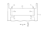
図2の記録装置11における記録部23と載置台27との間には、用紙Pを反転させる反転経路である第3媒体供給路33の一部を形成する経路形成部材61が配置されたが、本発明は、経路形成部材61を備えない記録装置にも適用する。図26の記録装置11aには、図2の経路形成部材61、分岐機構43、分岐搬送路ローラー対45、分岐搬送路44、第3駆動ローラー46a、第3従動ローラー46bが備えられない。また、記録部23の上側には、搬送ローラー対25が備えられない。   Although a path forming member 61 that forms a part of the third medium supply path 33 that is a reversing path for reversing the sheet P is disposed between the recording unit 23 and the mounting table 27 in the recording apparatus 11 in FIG. The present invention is also applied to a recording apparatus having no path forming member 61. 26 does not include the path forming member 61, the branching mechanism 43, the branch transport path roller pair 45, the branch transport path 44, the third drive roller 46a, and the third driven roller 46b in FIG. The transport roller pair 25 is not provided above the recording unit 23.

図26の記録装置11aの載置台27は、図2の記録装置11と同様に、一対の軸62を中心として回動可能に備えられる。記録装置11aにおいて、載置台27は、上から見たときの記録部23との重なり部分が、それぞれ閉じた状態よりも少なくなるまで開くことが可能に構成されている。載置台27を開けることで、記録部23に対して上方からアクセスし易くすることができる。記録装置11aのその他の構成は、記録装置11の構成と同じである。   The mounting table 27 of the recording device 11a in FIG. 26 is provided rotatably about a pair of shafts 62, similarly to the recording device 11 in FIG. In the recording device 11a, the mounting table 27 is configured to be openable until the overlapping portion with the recording unit 23 when viewed from above becomes smaller than a closed state. By opening the mounting table 27, the recording section 23 can be easily accessed from above. The other configuration of the recording device 11a is the same as the configuration of the recording device 11.

(実施形態2)
以下、記録装置の一実施形態として、液体の一例であるインクを吐出する記録部を備え、媒体の一例である用紙にインクを吐出して文字や図形などを含む画像を印刷(記録)するインクジェット式のプリンターについて、図を参照して説明する。
(Embodiment 2)
Hereinafter, as an embodiment of a recording apparatus, an ink jet that includes a recording unit that ejects ink that is an example of a liquid, and that prints (records) an image including characters and graphics by ejecting ink on paper that is an example of a medium. The formula printer will be described with reference to the drawings.

図12に示すように、本実施形態の記録装置の一例としてのプリンター111は、略直方体の筐体112と、図12に一点鎖線で示す搬送経路113に沿って用紙114を搬送する複数のローラー対を備える。さらに、搬送経路113には、用紙114を重力方向側から支持する支持台117と、搬送経路113を挟んで支持台117に対向するように配置された記録部118とを備える。   As shown in FIG. 12, a printer 111 as an example of a recording apparatus according to the present embodiment includes a substantially rectangular parallelepiped housing 112 and a plurality of rollers for transporting a sheet 114 along a transport path 113 shown by a dashed line in FIG. Have a pair. Further, the transport path 113 includes a support table 117 that supports the sheet 114 from the gravitational direction side, and a recording unit 118 that is disposed to face the support table 117 with the transport path 113 interposed therebetween.

記録部118は、搬送方向Yと交差(ここでは直交)する幅方向Xに亘ってインクを同時に吐出可能な液体吐出ヘッド170(図14参照)を有する所謂ラインヘッドであって、支持台117に支持された状態で通過する用紙114に向かってインクを吐出することにより印刷を行う。なお、以下の説明では、搬送経路113において支持台117と記録部118との間の位置を印刷位置119と呼称する。   The recording unit 118 is a so-called line head having a liquid ejection head 170 (see FIG. 14) capable of simultaneously ejecting ink in a width direction X crossing (here, orthogonal to) the conveyance direction Y. Printing is performed by discharging ink toward the paper 114 that passes while being supported. In the following description, a position between the support table 117 and the recording unit 118 on the transport path 113 is referred to as a printing position 119.

搬送経路113は、印刷位置119よりも搬送方向Yの上流側の第1供給経路121及び第2供給経路122と、印刷位置119よりも搬送方向Yの下流側の第3供給経路123、分岐経路124、及び排出経路125とにより構成されている。   The transport path 113 includes a first supply path 121 and a second supply path 122 upstream of the print position 119 in the transport direction Y, a third supply path 123 downstream of the print position 119 in the transport direction Y, and a branch path. 124 and a discharge path 125.

第1供給経路121は、筐体112の重力方向側となる底部に挿抜可能に備えられた用紙カセット127と、印刷位置119とを結ぶ経路である。そして、第1供給経路121には、用紙カセット127に積層状態で載置された用紙114のうち、最上位の用紙114を送り出すピックアップローラー128と、ピックアップローラー128により送り出された用紙114を1枚ずつ分離する分離ローラー129とが設けられている。さらに、分離ローラー129よりも搬送方向の下流側には、第1供給ローラー対131が設けられている。   The first supply path 121 is a path that connects a paper cassette 127 that can be inserted into and removed from the bottom of the housing 112 on the gravity direction side, and a printing position 119. In the first supply path 121, a pickup roller 128 for sending out the top sheet 114 among the sheets 114 stacked in the sheet cassette 127, and one sheet 114 sent out by the pickup roller 128. And a separation roller 129 that separates them one by one. Further, a first supply roller pair 131 is provided downstream of the separation roller 129 in the transport direction.

第2供給経路122は、筐体112一側面に備えられたカバー112aを開けることによって露出する挿入口112bと、印刷位置119とを結ぶ経路である。そして、第2供給経路122には、挿入口112bから挿入された用紙114を挟持して搬送する第2供給ローラー対132が設けられている。さらに、第1供給経路121と第2供給経路122と第3供給経路123とが合流した位置には、第3供給ローラー対133と第4供給ローラー対134とが設けられていると共に、第3供給経路123には、第5供給ローラー対135が設けられている。   The second supply path 122 is a path connecting the insertion position 112b exposed by opening the cover 112a provided on one side surface of the housing 112 and the printing position 119. The second supply path 122 is provided with a second supply roller pair 132 for nipping and transporting the sheet 114 inserted from the insertion port 112b. Further, at a position where the first supply path 121, the second supply path 122, and the third supply path 123 merge, a third supply roller pair 133 and a fourth supply roller pair 134 are provided. The supply path 123 is provided with a fifth supply roller pair 135.

第3供給経路123は、記録部118を囲うように設けられた経路であって、一旦印刷位置119を通過した用紙114を、再び印刷位置119よりも上流側へ戻すための経路である。すなわち、印刷位置119よりも下流側には、分岐機構136が設けられていると共に、排出経路125から分岐した分岐経路124には、正転と逆転の双方の回転が可能な分岐ローラー対137が設けられている。   The third supply path 123 is a path provided so as to surround the recording unit 118, and is a path for returning the sheet 114 that has once passed the printing position 119 to the upstream side from the printing position 119 again. That is, a branch mechanism 136 is provided downstream of the printing position 119, and a branch roller pair 137 that can rotate in both normal and reverse directions is provided in the branch path 124 branched from the discharge path 125. Is provided.

排出経路125は、印刷済みの用紙114が排出される排出口138と、印刷位置119とを結ぶ経路である。なお、排出口138から排出された用紙114は載置台139に載置される。そして、排出経路125には、少なくとも1つ(本実施形態では6個)の第1搬送ローラー対141〜第6搬送ローラー対146が設けられている。さらに、第3供給経路123にも第7搬送ローラー対147、及び第8搬送ローラー対148が設けられている。これらの第1搬送ローラー対141〜第8搬送ローラー対148は、インクが付着した用紙114を挟持して搬送する。   The discharge path 125 is a path connecting the discharge port 138 from which the printed sheet 114 is discharged and the printing position 119. The sheet 114 discharged from the discharge port 138 is placed on the placing table 139. The discharge path 125 is provided with at least one (six in this embodiment) first transport roller pairs 141 to sixth transport roller pairs 146. Further, the third supply path 123 is also provided with a seventh transport roller pair 147 and an eighth transport roller pair 148. The first transport roller pair 141 to the eighth transport roller pair 148 sandwich and transport the paper 114 to which the ink is attached.

すなわち、第1搬送ローラー対141〜第8搬送ローラー対148は、駆動源の駆動力に基づいて回転する円柱状の駆動ローラー150と、駆動ローラー150の回転に伴って従動回転する歯付きローラー149とにより構成されている。また、歯付きローラー149は、駆動ローラー150と対をなさずに単独でも設けられている。すなわち、歯付きローラー149は、第3供給経路123、分岐経路124、排出経路125において、用紙114の印刷が施された面である印刷面(すなわち、液体の一例であるインクが吐出されて付着する面)が通過する側に設けられている。また、歯付きローラー149は、搬送方向において第1搬送ローラー対141〜第8搬送ローラー対148の各搬送ローラー対の間にも設けられており、各搬送ローラー対と記録部118との間にも設けられている。一方、駆動ローラー150は、用紙114の印刷が施されていない非印刷面(非記録面)、もしくは両面印刷された用紙114では先に印刷された面が通過する側に設けられている。   That is, the first transport roller pair 141 to the eighth transport roller pair 148 include a cylindrical drive roller 150 that rotates based on the driving force of the drive source, and a toothed roller 149 that rotates following the rotation of the drive roller 150. It consists of: Further, the toothed roller 149 is provided alone without forming a pair with the drive roller 150. That is, the toothed roller 149 is attached to the third supply path 123, the branch path 124, and the discharge path 125 on the printing surface that is the surface on which the paper 114 is printed (that is, the ink that is an example of a liquid is ejected and adhered). Is provided on the side through which the surface passes. In addition, the toothed roller 149 is also provided between each pair of transport rollers of the first transport roller pair 141 to the eighth transport roller pair 148 in the transport direction, and between each transport roller pair and the recording unit 118. Is also provided. On the other hand, the drive roller 150 is provided on the non-printing surface (non-recording surface) of the paper 114 on which printing is not performed, or on the side on which the previously printed surface of the double-sided printed paper 114 passes.

本実施形態では、印刷位置119において、少なくとも第4供給ローラー対134が、記録部118に対向して、用紙114を支持台117に支持された状態で搬送する搬送部115として機能する。なお、第4供給ローラー対134は、図示しない駆動源によって回転駆動される駆動ローラー134aと、この駆動ローラー134aに従って回転する従動ローラー134bを有し、これらのローラー間に用紙114を挟持して搬送する。このため、駆動ローラー134aは用紙114が滑らないように表面が防滑処理されたローラーとされている。   In the present embodiment, at the printing position 119, at least the fourth supply roller pair 134 functions as the transport unit 115 that transports the sheet 114 while being supported by the support stand 117, facing the recording unit 118. The fourth supply roller pair 134 includes a drive roller 134a that is driven to rotate by a drive source (not shown) and a driven roller 134b that rotates according to the drive roller 134a. I do. For this reason, the drive roller 134a is a roller whose surface is subjected to anti-slip processing so that the paper 114 does not slip.

図13に示すように、記録部118には、幅方向Xにおける一端側(ここでは−X側)において、一端側貫通孔151を有する筒部153が設けられ、他端側(ここでは+X側)において他端側貫通孔152を有する平板部154が設けられている(図18参照)。一端側貫通孔151および他端側貫通孔152には、筐体112に備えられた基台部199(図16、図19参照)に設けられた一端側挿入軸191および他端側挿入軸192がそれぞれ挿入され、記録部118は、搬送方向Yにおいて位置決めされている。   As shown in FIG. 13, the recording section 118 is provided with a cylindrical section 153 having one end side through hole 151 at one end side (here, -X side) in the width direction X, and the other end side (here, + X side). ), A flat plate portion 154 having the other end side through hole 152 is provided (see FIG. 18). One end side insertion shaft 191 and the other end side insertion shaft 192 provided in the base part 199 (see FIGS. 16 and 19) provided in the housing 112 are provided in the one end side through hole 151 and the other end side through hole 152. Are inserted, and the recording unit 118 is positioned in the transport direction Y.

本実施形態では、筒部153が有する一端側貫通孔151は、軸断面が円形の一端側挿入軸191の軸線方向において間隔を設けて筒部153に装着された第1ブッシュ155と第2ブッシュ156によって形成されている。すなわち、筒部153には、挿入される一端側挿入軸191の挿入方向において、支持台117に近い側端部に第1ブッシュ155が、また支持台117から遠い側端部に第2ブッシュ156が、それぞれ打ち込みなどによって装着されている。   In the present embodiment, the first bush 155 and the second bush 155 mounted on the cylindrical portion 153 are spaced from each other in the axial direction of the one end insertion shaft 191 having a circular axial cross section. 156. That is, in the insertion direction of the one end side insertion shaft 191 to be inserted, the first bush 155 is provided on the side end near the support base 117 and the second bush 156 is provided on the side end far from the support base 117 in the cylindrical part 153. Are attached by driving or the like.

そして、第1ブッシュ155には円形孔の第1貫通孔151Aが設けられ、第2ブッシュ156には、記録部118の長手方向(幅方向X)に沿う直線状の平行縁部L3を有し、他の部分が半円縁部R3とされた、長孔の一例である長円形孔の第2貫通孔151B(図18参照)が設けられている。したがって、記録部118の長手方向の一端側には、第1貫通孔151Aと、この第1貫通孔151Aよりも用紙114の記録面114Pから遠い位置に設けられ、一端側挿入軸191が挿入される第2貫通孔151Bと、が備えられる。これらの円形の第1貫通孔151Aと長円形の第2貫通孔151Bとによって、一端側挿入軸191が挿入される一端側貫通孔151が形成されている。   The first bush 155 is provided with a first through hole 151A having a circular shape, and the second bush 156 has a linear parallel edge L3 along the longitudinal direction (width direction X) of the recording unit 118. A second through-hole 151B (see FIG. 18) of an oval hole, which is an example of an oval hole, provided with a semicircular edge portion R3 at the other portion. Therefore, the first through-hole 151A and the farther from the recording surface 114P of the paper 114 than the first through-hole 151A are provided at one end side in the longitudinal direction of the recording unit 118, and the one-end-side insertion shaft 191 is inserted. And a second through hole 151B. One end side through hole 151 into which one end side insertion shaft 191 is inserted is formed by the circular first through hole 151A and the oval second through hole 151B.

一方、平板部154に設けられた他端側貫通孔152は、記録部118の長手方向(幅方向X)に沿う直線状の平行縁部L2を有し、他の部分が半円縁部R2とされた、長孔の一例である長円形孔(図18参照)で設けられている。そして、この長円形の他端側貫通孔152に挿入される他端側挿入軸192は、基台部199に固定された軸断面が円形の他端側固定軸193と、この他端側固定軸193の中心軸線から所定の寸法だけ偏心した軸線を中心軸とする円筒面を外面に有し、その円筒面が他端側固定軸193を中心に回動可能な偏心円筒部材194とで構成されている。   On the other hand, the other end side through-hole 152 provided in the flat plate portion 154 has a linear parallel edge portion L2 along the longitudinal direction (width direction X) of the recording portion 118, and the other portion has a semicircular edge portion R2. And an oval hole (see FIG. 18) which is an example of an elongate hole. The other end side insertion shaft 192 inserted into the oval other end side through hole 152 is connected to the other end side fixed shaft 193 fixed to the base portion 199 and having a circular cross section. The outer surface has a cylindrical surface whose center axis is an axis eccentric by a predetermined dimension from the center axis of the shaft 193, and the cylindrical surface is constituted by an eccentric cylindrical member 194 rotatable around the other end side fixed shaft 193. Have been.

なお、一端側挿入軸191は基台部199の一端側に固定された一端側固定軸であり、この一端側挿入軸191には、固定された基台部199の部分から用紙114側へ突出した一端側軸突出部191Aが設けられている。また、基台部199の他端側に固定された他端側固定軸193には、同じく基台部199から用紙114側へ突出した他端側軸突出部193Aが設けられている。この一端側軸突出部191Aおよび他端側軸突出部193Aは、後述する記録部118に対するキャップ172の位置決めに際して用いられる。   The one end side insertion shaft 191 is a fixed end side fixed shaft fixed to one end side of the base portion 199. The one end side insertion shaft 191 projects from the fixed base portion 199 to the paper 114 side from the fixed base portion 199 portion. One end side shaft protrusion 191A is provided. The other end side fixed shaft 193 fixed to the other end side of the base 199 is provided with the other end side shaft protrusion 193A that also projects from the base 199 to the paper 114 side. The one end side shaft protrusion 191A and the other end side shaft protrusion 193A are used when positioning the cap 172 with respect to the recording unit 118 described later.

また、本実施形態では、記録部118の長手方向となる幅方向Xは、搬送部115による用紙114の搬送方向Y及び当該用紙114の記録面114Pの法線に沿う方向の双方と交差する方向とされている。そして、この長手方向における両端部のそれぞれに設けられた一端側貫通孔151および他端側貫通孔152は、記録面114Pの法線に沿う方向に貫通する貫通孔とされ、貫通孔に挿入される挿入軸である一端側挿入軸191と他端側挿入軸192(詳しくは他端側固定軸193)の軸線方向は、用紙114の記録面114Pの法線に沿う方向とされている。   In the present embodiment, the width direction X that is the longitudinal direction of the recording unit 118 is a direction that intersects both the transport direction Y of the sheet 114 by the transport unit 115 and the direction along the normal to the recording surface 114P of the sheet 114. It has been. One end-side through-hole 151 and the other end-side through-hole 152 provided at both ends in the longitudinal direction are through-holes penetrating in a direction along the normal line of the recording surface 114P, and are inserted into the through-holes. The axial directions of the one-end insertion shaft 191 and the other-end insertion shaft 192 (specifically, the other-end fixed shaft 193), which are insertion shafts, are directions along the normal line of the recording surface 114 </ b> P of the paper 114.

したがって、記録部118は、このように長手方向(幅方向X)の両側に設けられた一端側貫通孔151と他端側貫通孔152とが、それぞれに挿入された一端側挿入軸191と他端側挿入軸192(詳しくは偏心円筒部材194)の軸線方向に移動することによって用紙114の記録面114Pの法線方向に沿って移動する。この結果、記録部118は、用紙114(支持台117)に対して離れたり近づいたりする移動によって、搬送経路113を搬送される用紙114(あるいは支持台117)との間の隙間の大きさが調整される。   Therefore, the recording unit 118 is configured such that the one end side through-hole 151 and the other end side through-hole 152 provided on both sides in the longitudinal direction (the width direction X) are different from the one end-side insertion shaft 191 inserted into each of them. By moving in the axial direction of the end insertion shaft 192 (specifically, the eccentric cylindrical member 194), the paper 114 moves along the normal direction of the recording surface 114P of the paper 114. As a result, the size of the gap between the recording unit 118 and the sheet 114 (or the support table 117) conveyed along the conveyance path 113 by the movement of moving away from or approaching the sheet 114 (the support table 117) is reduced. Adjusted.

次に、記録部118と用紙114との間の隙間の調整構造について説明する。なお、一端側挿入軸191および他端側挿入軸192の軸線方向、つまり記録部118が移動可能な方向を、移動方向Aとして説明する。   Next, the adjustment structure of the gap between the recording unit 118 and the sheet 114 will be described. The axial direction of the one end insertion shaft 191 and the other end insertion shaft 192, that is, the direction in which the recording unit 118 can move, will be described as a movement direction A.

図13および図14に示すように、記録部118には、少なくとも1つの被係合部157と複数の従節部158とが、記録部118における搬送方向Yの上流側の側面から突出して形成されている。なお、本実施形態では、幅方向Xに隣り合う1つの被係合部157と1つの従節部158とを1組として、2組の被係合部157と従節部158とが組ごとに幅方向Xにおいて間隔を有して設けられている。   As shown in FIGS. 13 and 14, at least one engaged portion 157 and a plurality of followers 158 are formed on the recording portion 118 so as to protrude from the upstream side surface of the recording portion 118 in the transport direction Y. Have been. In the present embodiment, one engaged portion 157 and one follower portion 158 adjacent in the width direction X are regarded as one set, and two sets of the engaged portion 157 and the follower portion 158 are combined with each other. Are provided with an interval in the width direction X.

また、被係合部157と従節部158は、幅方向X及び移動方向Aにおいて位置をずらして設けられるとともに、従節部158の用紙114側となる下面が、被係合部157の用紙114とは反対側となる上面よりも、用紙114から離れた位置に位置するように形成されている。   The engaged portion 157 and the follower portion 158 are provided so as to be displaced from each other in the width direction X and the movement direction A, and the lower surface of the follower portion 158 on the paper 114 side is formed of the paper of the engaged portion 157. It is formed so as to be located at a position farther from the sheet 114 than the upper surface opposite to the side 114.

そして、記録部118の被係合部157と従節部158とが形成された側には、従節部158を介して記録部118を移動させることにより、記録部118を用紙114の表裏面のうちの少なくとも一方の面である記録面114P(印刷面)に対して相対的に移動させる移動部160が設けられている。   By moving the recording unit 118 via the follower 158 to the side of the recording unit 118 where the engaged portion 157 and the follower 158 are formed, the recording unit 118 A moving unit 160 for relatively moving the recording surface 114P (printing surface), which is at least one of the surfaces, is provided.

すなわち、移動部160は、図14に示すように、正転と逆転の双方の回転が可能な調整モーター161と、調整モーター161の駆動力を伝達するための伝達機構162と、伝達機構162に伝達された駆動力により正転と逆転の双方の方向に回動する回動軸163とを備えている。回動軸163は、幅方向Xに沿って延びるように設けられ、この回動軸163には、各従節部158と対応するように幅方向Xに間隔を有して複数(本実施形態では2つ)のカム165が設けられている。   That is, as shown in FIG. 14, the moving unit 160 includes an adjustment motor 161 capable of rotating in both forward and reverse directions, a transmission mechanism 162 for transmitting the driving force of the adjustment motor 161, and a transmission mechanism 162. A rotating shaft 163 that rotates in both forward and reverse directions by the transmitted driving force. The rotating shaft 163 is provided so as to extend along the width direction X. The rotating shaft 163 has a plurality of rotating shafts 163 at intervals in the width direction X so as to correspond to the followers 158 (this embodiment). In this case, two cams 165 are provided.

カム165は、図13,図14に示すように略円盤形状をなし、中心とは異なる位置に回動軸163が挿通された偏心カムとされている。そして、このカム165は、カムフォロアーとしての従節部158に接触しながら回動軸163と共に回動することにより、従節部158を介して記録部118を移動方向Aに沿って移動させる。すなわち、カム165は、記録部118を、用紙114(支持台117)から離れるように移動方向Aに沿って上方へ移動させたり、用紙114に近づくように移動方向Aに沿って下方へ移動させたりして、記録部118の移動方向Aにおける位置を調整する。   The cam 165 has a substantially disk shape as shown in FIGS. 13 and 14, and is an eccentric cam in which the rotation shaft 163 is inserted at a position different from the center. The cam 165 rotates along with the rotation shaft 163 while contacting the follower 158 as a cam follower, thereby moving the recording unit 118 along the movement direction A via the follower 158. That is, the cam 165 causes the recording unit 118 to move upward along the moving direction A so as to separate from the sheet 114 (the support table 117), or to move downward along the moving direction A so as to approach the sheet 114. To adjust the position of the recording unit 118 in the movement direction A.

さらに、回動軸163には、該回動軸163と共に回動して記録部118の被係合部157と係合可能な係合部166が、被係合部157と対応するように少なくとも1つ設けられている。すなわち、本実施形態では、2つの係合部166が幅方向Xにおいて間隔を有して設けられている。   Further, the rotating shaft 163 has at least an engaging portion 166 that can rotate with the rotating shaft 163 and engage with the engaged portion 157 of the recording unit 118 so as to correspond to the engaged portion 157. One is provided. That is, in the present embodiment, the two engaging portions 166 are provided with an interval in the width direction X.

係合部166は、回動軸163に支持された基端部167と、基端部167に対して折れ曲がるような形状に形成された鉤部168とにより構成されている。また、係合部166は、鉤部168の先端の厚みが他の部分の厚みよりも厚くされている。また、回動軸163の中心から被係合部157と係合する鉤部168の内側の面までの距離(内径)は、この距離(内径)と同方向におけるカム165の外径と同じ寸法とされている。   The engagement portion 166 includes a base end 167 supported by the rotation shaft 163 and a hook 168 formed to be bent with respect to the base end 167. The engaging portion 166 is formed such that the tip of the hook portion 168 is thicker than other portions. The distance (inner diameter) from the center of the rotating shaft 163 to the inner surface of the hook 168 engaging with the engaged portion 157 is the same as the outer diameter of the cam 165 in the same direction as this distance (inner diameter). It has been.

本実施形態では、被係合部157と回動軸163は、移動方向Aに沿って並んで設けられている。すなわち、被係合部157は、回動軸163の上まで延びるように形成されて、被係合部157と搬送経路113との間に回動軸163が位置している。そのため、図13に示す状態から調整モーター161が正転駆動すると、係合部166が回動軸163の回動に伴って正回動(図13では反時計回り方向に回動)する。そして、図14に示すように、移動方向Aに沿って回動軸163と被係合部157と係合部166の鉤部168とが並ぶ状態となる。したがって、係合部166は、移動方向Aにおいて、用紙114(支持台117)が位置する側とは逆の方向(図13では上側)から被係合部157に係合可能となる。   In the present embodiment, the engaged portion 157 and the rotating shaft 163 are provided side by side along the movement direction A. That is, the engaged portion 157 is formed so as to extend above the rotating shaft 163, and the rotating shaft 163 is located between the engaged portion 157 and the transport path 113. Therefore, when the adjustment motor 161 is driven to rotate forward from the state shown in FIG. 13, the engaging portion 166 rotates forward (rotates counterclockwise in FIG. 13) with the rotation of the rotation shaft 163. Then, as shown in FIG. 14, the rotating shaft 163, the engaged portion 157, and the hook 168 of the engaging portion 166 are aligned along the moving direction A. Accordingly, the engaging portion 166 can be engaged with the engaged portion 157 in the moving direction A from the direction opposite to the side where the sheet 114 (the support base 117) is located (the upper side in FIG. 13).

さらに、本実施形態では、回動軸163の両側を回動自在に支持する軸受のうち少なくとも一方の軸受が記録部118の移動方向Aに沿って移動可能とされている。すなわち、図14に示すように、幅方向Xにおける一端側(−X側)の軸受169が、調節ねじ169Aの回転によって移動方向Aに沿って移動する軸受移動機構が構成されている。   Further, in the present embodiment, at least one of the bearings rotatably supporting both sides of the rotating shaft 163 is movable along the moving direction A of the recording unit 118. That is, as shown in FIG. 14, a bearing moving mechanism in which the bearing 169 on one end side (−X side) in the width direction X moves along the moving direction A by the rotation of the adjusting screw 169A.

このように構成された軸受移動機構により、調節ねじ169Aを回転させることによって一端側の軸受169が移動方向Aにおいて上下移動し、この一端側の軸受169に軸支された回動軸163の一端側を他端側に対して相対的に上下移動させる。この回動軸163の一端側の上下移動に伴って一端側のカム165が従節部158を介して記録部118の一端側を移動方向Aに沿って上下移動させることになる。これにより、記録部118は幅方向Xにおいて用紙114(支持台117)と平行になるように調節される。   By rotating the adjustment screw 169A by the bearing moving mechanism configured as described above, the bearing 169 on one end moves up and down in the moving direction A, and one end of the rotating shaft 163 supported by the bearing 169 on one end. Is moved up and down relatively to the other end. As the one end of the rotation shaft 163 moves up and down, the cam 165 at one end moves the one end of the recording unit 118 up and down along the movement direction A via the follower 158. Accordingly, the recording unit 118 is adjusted so as to be parallel to the sheet 114 (the support table 117) in the width direction X.

また、図13に示すように、記録部118の支持台117側となる下面には、インクを吐出するノズルNが複数(図13では1つのみ図示)形成された液体吐出ヘッド170が設けられている。そして、プリンター111は、支持台117側となる下面側から記録部118に接触してノズルNが臨む空間を密閉可能なキャップ172と、キャップ172及び支持台117を記録部118に対して相対移動させて入れ替える入替機構171と、を備えている。   As shown in FIG. 13, a liquid ejection head 170 having a plurality of nozzles N for ejecting ink (only one is shown in FIG. 13) is provided on the lower surface of the recording unit 118 on the support table 117 side. ing. Then, the printer 111 contacts the recording unit 118 from the lower surface side, which is the support table 117 side, and moves the cap 172 capable of sealing the space facing the nozzle N, and moves the cap 172 and the support table 117 relative to the recording unit 118. And a replacement mechanism 171 for performing the replacement.

キャップ172は、記録部118側となる上端が開口した有底矩形箱状のキャップホルダー173と、キャップホルダー173内に少なくとも1つのばねを介して配置された有底箱状のキャップ形成部材173Aとを備えている。キャップホルダー173には、その幅方向Xの両側に、移動方向Aに沿って上方へ延設された一端側延設部174と他端側延設部175とがそれぞれ形成されているとともに、一端側延設部174には一端側穴部174Aが設けられ、他端側延設部175には他端側穴部175Aが設けられている(図16参照)。   The cap 172 includes a bottomed rectangular box-shaped cap holder 173 having an open upper end on the recording unit 118 side, and a bottomed box-shaped cap forming member 173A disposed in the cap holder 173 via at least one spring. It has. One end extending portion 174 and the other end extending portion 175 extending upward along the moving direction A are formed on both sides of the cap holder 173 in the width direction X, respectively. The side extension 174 is provided with one end side hole 174A, and the other end side extension 175 is provided with another end side hole 175A (see FIG. 16).

入替機構171は、正転と逆転の双方の回転が可能な移動モーターMと、移動モーターMの回転に伴って正方向と逆方向の双方の方向に回転するスクリュー軸176と、スクリュー軸176と螺合したキャップ側スライダー178及び支持台側スライダー179と、を備えている。そして、キャップ側スライダー178は、対をなして設けられた第1外側リンク部材181aと第1内側リンク部材181bとによりキャップ172と接続されている。また、支持台側スライダー179は、対をなして設けられた第2外側リンク部材182aと第2内側リンク部材182bとにより支持台117と接続されている。   The exchange mechanism 171 includes a moving motor M that can rotate in both forward and reverse directions, a screw shaft 176 that rotates in both forward and reverse directions with the rotation of the moving motor M, and a screw shaft 176. A cap-side slider 178 and a support base-side slider 179 that are screwed together are provided. The cap-side slider 178 is connected to the cap 172 by a first outer link member 181a and a first inner link member 181b provided as a pair. The support-side slider 179 is connected to the support 117 via a second outer link member 182a and a second inner link member 182b provided as a pair.

また、壁部材183には、キャップ側ガイドレール184と支持台側ガイドレール185とが、直線部分となだらかなS字の曲線部分とを描くように設けられた長孔で形成されている。なお、キャップ側ガイドレール184と支持台側ガイドレール185は、搬送方向Yにおいて記録部118が設けられた位置を基準として、移動方向Aに延びる基準線(図示略)に対して線対称となるように形成されている。すなわち、キャップ側ガイドレール184と支持台側ガイドレール185は、基準線側となる中央側の各端部が移動方向Aにおいて記録部118に近い上側に位置し、基準線から離れた外側の各端部が移動方向Aにおいて記録部118から離れた下側に位置するように形成されている。   In the wall member 183, a cap side guide rail 184 and a support base side guide rail 185 are formed by long holes provided so as to draw a straight line portion and a gentle S-shaped curved portion. Note that the cap-side guide rail 184 and the support base-side guide rail 185 are symmetric with respect to a reference line (not shown) extending in the movement direction A with respect to the position where the recording unit 118 is provided in the transport direction Y. It is formed as follows. That is, the cap-side guide rail 184 and the support base-side guide rail 185 are such that each end on the center side, which is the reference line side, is located on the upper side close to the recording unit 118 in the movement direction A, and each of the outer sides separated from the reference line The end is formed so as to be located on the lower side away from the recording unit 118 in the moving direction A.

そして、キャップ側ガイドレール184には、キャップ172に接続された第1外側リンク部材181aに設けられたキャップ側ガイド部186がキャップ側ガイドレール184に沿って移動可能に挿入されている。一方、支持台側ガイドレール185には、支持台117に接続された第2外側リンク部材182aに設けられた支持台側ガイド部187が支持台側ガイドレール185に沿って移動可能に挿入されている。   The cap-side guide portion 186 provided on the first outer link member 181 a connected to the cap 172 is movably inserted into the cap-side guide rail 184 along the cap-side guide rail 184. On the other hand, a support-side guide portion 187 provided on the second outer link member 182a connected to the support 117 is movably inserted into the support-side guide rail 185 along the support-side guide rail 185. I have.

図15および図16に示すように、キャップ172は、入替機構171の動作によって記録部118に対する支持台117との位置の入れ替えが行われる。すなわち、図13に示す状態において移動モーターMが逆転駆動すると、キャップ側スライダー178及び支持台側スライダー179は、移動モーターMから離れるようにスクリュー軸176の軸方向に沿って移動する。   As shown in FIGS. 15 and 16, the position of the cap 172 is exchanged with the support stand 117 with respect to the recording unit 118 by the operation of the exchange mechanism 171. That is, when the moving motor M is driven to rotate in the reverse direction in the state shown in FIG. 13, the cap-side slider 178 and the support-side slider 179 move along the axial direction of the screw shaft 176 so as to move away from the moving motor M.

すると、図15において二点鎖線で示すように、非密閉位置Dに位置したキャップ172はまずキャップ側ガイド部186がキャップ側ガイドレール184の直線部分に沿って移動することによって搬送方向Yに沿って搬送方向Yとは逆方向の中間位置Gへ移動する。次に、キャップ側ガイド部186がキャップ側ガイドレール184の曲線部分に沿って移動することによって、キャップ172は中間位置Gから移動方向Aに沿って上昇し、記録部118に対してその下面側に当接する密閉位置Bへ移動する。このとき、図13の支持位置Eに位置した支持台117は、支持台側スライダー179の移動によって、キャップ172の中間位置Gへの移動に先んじて図15の非支持位置Cへ移動する。   Then, as shown by a two-dot chain line in FIG. 15, the cap 172 located at the non-sealing position D first moves along the straight portion of the cap-side guide rail 184 by the cap-side guide portion 186 to move in the transport direction Y. To the intermediate position G in the direction opposite to the transport direction Y. Next, when the cap-side guide portion 186 moves along the curved portion of the cap-side guide rail 184, the cap 172 rises from the intermediate position G in the moving direction A, and the lower side of the recording portion 118 with respect to the recording portion 118. To the closed position B in contact with. At this time, the support table 117 located at the support position E in FIG. 13 moves to the non-support position C in FIG. 15 before the cap 172 moves to the intermediate position G by the movement of the support table slider 179.

また、この状態から移動モーターMが正転駆動すると、キャップ側スライダー178及び支持台側スライダー179は、移動モーターMの回転に伴って移動モーターMに近づくようにスクリュー軸176の軸方向に沿って移動する。すると、図13に示すように、キャップ172は記録部118から離れるように移動して密閉位置Bとは異なる非密閉位置Dまで中間位置Gを経由して移動する。一方、支持台117は、記録部118に近づくように移動して用紙114を支持する支持位置Eまで移動する。したがって、入替機構171は、キャップ172を密閉位置Bと非密閉位置Dとの間で移動させると共に、支持台117を非支持位置Cと支持位置Eとの間で移動させる。   When the moving motor M is driven to rotate forward from this state, the cap-side slider 178 and the support base-side slider 179 move along the axial direction of the screw shaft 176 so as to approach the moving motor M with the rotation of the moving motor M. Moving. Then, as shown in FIG. 13, the cap 172 moves away from the recording unit 118 and moves to the non-sealing position D different from the sealing position B via the intermediate position G. On the other hand, the support stand 117 moves closer to the recording unit 118 and moves to a support position E where the paper 114 is supported. Therefore, the replacement mechanism 171 moves the cap 172 between the closed position B and the non-sealed position D, and moves the support table 117 between the non-supported position C and the supported position E.

そして、図15、図16および図17に示すように、本実施形態では、キャップ172が中間位置Gから密閉位置Bへ、移動方向Aに沿って上昇移動する際に、記録部118に対して位置決めされる。すなわち、基台部199に固定された一端側挿入軸191の一端側軸突出部191Aが、キャップ172の一端側延設部174に設けられた一端側穴部174Aに挿入され、他端側挿入軸192に設けられた他端側軸突出部193Aが、キャップ172の他端側延設部175に設けられた他端側穴部175Aに挿入される。この結果、キャップ172は基台部199に固定された一端側挿入軸191および他端側挿入軸192(詳しくは他端側固定軸193)によって、搬送方向Yおよび幅方向Xにおいて位置決めされる。   Then, as shown in FIGS. 15, 16 and 17, in the present embodiment, when the cap 172 moves upward from the intermediate position G to the closed position B along the moving direction A, the cap 172 moves with respect to the recording unit 118. Positioned. That is, the one end side shaft protrusion 191A of the one end side insertion shaft 191 fixed to the base 199 is inserted into the one end side hole 174A provided in the one end side extension 174 of the cap 172, and the other end side insertion is performed. The other end side shaft projection 193A provided on the shaft 192 is inserted into the other end side hole 175A provided on the other end side extension 175 of the cap 172. As a result, the cap 172 is positioned in the transport direction Y and the width direction X by the one-end insertion shaft 191 and the other-end insertion shaft 192 (specifically, the other-end fixed shaft 193) fixed to the base 199.

一方、図17および図18に示すように、記録部118は一端側挿入軸191および他端側挿入軸192(詳しくは偏心円筒部材194)によって位置決めされる。すなわち、図18において符号S1で示す矩形領域内に拡大図示するように、記録部118の一端側の第1貫通孔151Aの外形寸法H1は、この第1貫通孔151A内に位置する一端側挿入軸191の外形寸法J1との差が、例えば製造誤差に起因する最少寸法差とされる。この結果、記録部118の一端側は、この第1ブッシュ155の第1貫通孔151Aに挿入される一端側挿入軸191によって、搬送方向Yおよび幅方向Xの双方への移動が抑制されて位置決めされる。   On the other hand, as shown in FIGS. 17 and 18, the recording section 118 is positioned by the one-end insertion shaft 191 and the other-end insertion shaft 192 (specifically, the eccentric cylindrical member 194). That is, as shown in an enlarged manner in a rectangular area indicated by reference numeral S1 in FIG. 18, the outer dimension H1 of the first through-hole 151A at one end of the recording unit 118 is different from that of the first through-hole 151A located within the first through-hole 151A. The difference between the outer dimension J1 of the shaft 191 and the outer dimension J1 is the minimum dimensional difference due to, for example, a manufacturing error. As a result, one end side of the recording section 118 is positioned by the one end side insertion shaft 191 inserted into the first through hole 151A of the first bush 155 so that movement in both the transport direction Y and the width direction X is suppressed. Is done.

また、図18において符号S2で示す矩形領域内に拡大して図示するように、記録部118の他端側貫通孔152の平行縁部間の寸法H2は、この他端側貫通孔152内に位置する偏心円筒部材194の外形寸法J2との差が、例えば製造誤差に起因する最少寸法差とされる。この結果、記録部118の他端側は、この他端側貫通孔152に挿入される他端側挿入軸192の偏心円筒部材194によって搬送方向Yへの移動が抑制されて位置決めされる。   As shown in FIG. 18 in an enlarged manner in a rectangular area indicated by reference numeral S2, a dimension H2 between the parallel edge portions of the other end side through hole 152 of the recording unit 118 is set in the other end side through hole 152. The difference from the outer dimension J2 of the eccentric cylindrical member 194 located is, for example, the minimum dimensional difference due to a manufacturing error. As a result, the other end side of the recording unit 118 is positioned by the eccentric cylindrical member 194 of the other end side insertion shaft 192 inserted into the other end side through hole 152 with the movement in the transport direction Y being suppressed.

さらに、図18において符号S3で示す領域内に拡大して図示するように、記録部118の一端側の第2貫通孔151Bは、他端側貫通孔152と同様に、その平行縁部間の寸法H3は、第2貫通孔151B内に位置する一端側挿入軸191の外形寸法J3との差が、例えば製造誤差に起因する最少寸法差とされている。この結果、記録部118の一端側は、この第2ブッシュ156の第2貫通孔151Bに挿入される一端側挿入軸191によっても、搬送方向Yへの移動が抑制されて位置決めされる。このため、記録部118は搬送方向Yから見て異なる3つの位置にそれぞれ配設された第1貫通孔151A、第2貫通孔151B、および他端側貫通孔152において搬送方向Yへの移動が抑制され、幅方向Xに沿う軸線を中心とする回転(傾き)が抑制される。   18, the second through-hole 151B at one end of the recording unit 118 is disposed between the parallel edges of the recording unit 118 in the same manner as the through-hole 152 at the other end. The difference between the dimension H3 and the outer dimension J3 of the one end side insertion shaft 191 located in the second through hole 151B is a minimum dimension difference due to, for example, a manufacturing error. As a result, one end side of the recording section 118 is positioned while being prevented from moving in the transport direction Y by the one end insertion shaft 191 inserted into the second through hole 151B of the second bush 156. Therefore, the recording unit 118 moves in the transport direction Y at the first through-hole 151A, the second through-hole 151B, and the other end-side through-hole 152 provided at three different positions when viewed from the transport direction Y. The rotation (tilt) about the axis along the width direction X is suppressed.

従って、図17に示すように、搬送方向Yおよび幅方向Xの双方において、記録部118は、基台部199に固定された一端側挿入軸191と他端側挿入軸192とによって位置決めされ、キャップ172は、基台部199に固定された一端側挿入軸191と他端側挿入軸192とによって位置決めされる。換言すれば、キャップ172は、基台部199に固定された一端側挿入軸191と他端側挿入軸192とを介して、記録部118に対して位置決めされる。このようにキャップ172が記録部118に対して位置決めされることで、記録部118の下面に設けられた液体吐出ヘッド170に対して、キャップ172が密閉位置Bにおいて位置ずれが抑制された適切な状態で接触して、記録部118が臨む空間を覆う。   Therefore, as shown in FIG. 17, in both the transport direction Y and the width direction X, the recording unit 118 is positioned by the one-end insertion shaft 191 and the other-end insertion shaft 192 fixed to the base unit 199, and The cap 172 is positioned by one end side insertion shaft 191 and the other end side insertion shaft 192 fixed to the base 199. In other words, the cap 172 is positioned with respect to the recording unit 118 via the one-end insertion shaft 191 and the other-end insertion shaft 192 fixed to the base 199. By positioning the cap 172 with respect to the recording unit 118 in this manner, the cap 172 is appropriately positioned in the closed position B with respect to the liquid ejection head 170 provided on the lower surface of the recording unit 118 so as to suppress displacement. In this state, it covers the space where the recording unit 118 faces.

なお、キャップ172が密閉位置Bに位置する際、記録部118はキャップホルダー173内に少なくとも1つのばね(不図示)を介して配置された有底箱状のキャップ形成部材173Aによって移動方向Aに沿って下方から押し上げられる。そこで、本実施形態では、図15に示すように、係合部166を回動軸163の回動に伴って正回動させ、移動方向Aに沿って回動軸163と被係合部157と係合部166の鉤部168とが並ぶ状態にさせる。こうすることによって、係合部166は、移動方向Aにおいて、用紙114(支持台117)が位置する側とは逆の方向から被係合部157に係合する。この係合部166の被係合部157への上方からの係合によって、記録部118がキャップ形成部材173Aによって用紙114側の下方側から押し上げられた際に、移動方向Aにおける記録部118の上方への移動を抑制する。   When the cap 172 is located at the closed position B, the recording unit 118 is moved in the moving direction A by a bottomed box-shaped cap forming member 173A disposed in the cap holder 173 via at least one spring (not shown). It is pushed up from below along. Therefore, in the present embodiment, as shown in FIG. 15, the engaging portion 166 is positively rotated along with the rotation of the rotation shaft 163, and the rotation shaft 163 and the engaged portion 157 are moved along the movement direction A. And the hook 168 of the engaging portion 166 are aligned. By doing so, the engaging portion 166 engages with the engaged portion 157 in the movement direction A from the direction opposite to the side where the sheet 114 (the support stand 117) is located. When the recording unit 118 is pushed up from below by the cap forming member 173A by the cap forming member 173A due to the engagement of the engaging unit 166 with the engaged unit 157 from above, the recording unit 118 in the moving direction A is displaced. Suppress upward movement.

さて、図18に示すように、記録部118が備える液体吐出ヘッド170は、その長手方向(幅方向X)の両端が、長手方向と直交する方向から傾いた斜辺を有する略平行四辺形の外形形状とされ、記録部118の長手方向に沿って併設された複数(ここでは6つ)の個別ヘッドを含んで構成されている。この液体吐出ヘッド170には、複数のノズルNが液体吐出ヘッド170の平行四辺形の斜辺170Rと平行に並んで配列されたノズル列NRが、記録部118の長手方向に所定の間隔をあけて複数並んで設けられている。したがって、キャップ172は、この略平行四辺形とされた液体吐出ヘッド170に応じて、キャップホルダー173内のキャップ形成部材173Aが、外形が略平行四辺形の複数の有底箱状の個別キャップで形成されるとともに、複数の個別ヘッドを含んで構成される液体吐出ヘッド170に対して複数の個別キャップが接触する構成とされている(図16参照)。   As shown in FIG. 18, the liquid ejection head 170 provided in the recording unit 118 has a substantially parallelogram-shaped outer shape having oblique sides whose both ends in the longitudinal direction (width direction X) are inclined from a direction perpendicular to the longitudinal direction. The recording unit 118 includes a plurality of (in this case, six) individual heads provided along the longitudinal direction of the recording unit 118. In the liquid ejection head 170, a nozzle row NR in which a plurality of nozzles N are arranged in parallel with the oblique side 170R of the parallelogram of the liquid ejection head 170 is arranged at predetermined intervals in the longitudinal direction of the recording unit 118. A plurality is provided side by side. Therefore, according to the liquid ejection head 170 having a substantially parallelogram shape, the cap forming member 173A in the cap holder 173 is formed of a plurality of bottomed box-shaped individual caps having a substantially parallelogram outer shape. The plurality of individual caps are formed and are in contact with the liquid ejection head 170 including the plurality of individual heads (see FIG. 16).

また、図18に示すように、記録部118は、移動方向Aから見て略矩形形状の外形を有し、この矩形形状内に略平行四辺形とされた液体吐出ヘッド170が設けられている。このため、記録部118における平板部154の長手方向の両端には、この長手方向と直交する短手方向(搬送方向Y)において互いにずれた位置に、液体吐出ヘッド170が設けられていない略三角形領域Rがそれぞれ形成される。そこで、本実施形態では、この長手方向の両側の略三角形領域Rにおいて、一方側に一端側貫通孔151を、他方側に他端側貫通孔152を、それぞれ形成する。こうすることによって、一端側貫通孔151および他端側貫通孔152は、液体吐出ヘッド170の内の、最も記録部118の長手方向における一方の端部の側および他方の端部の側に近い液体吐出ヘッド170(個別ヘッド)と、記録部118の搬送方向Yにおいて重なるように配置される。この結果、記録部118の外形を長手方向や短手方向へ延ばしてその形状を大きくすることなく、記録部118を位置決めするための貫通孔を形成することが可能であり、記録部118の傾き補正を行うための機構を配置するスペースを省スペース化して、プリンター111の外形サイズが大きくならないように抑制することができる。   As shown in FIG. 18, the recording unit 118 has a substantially rectangular outer shape when viewed from the movement direction A, and a liquid ejection head 170 having a substantially parallelogram shape is provided in the rectangular shape. . For this reason, a substantially triangular shape in which the liquid ejection head 170 is not provided at both ends in the longitudinal direction of the flat plate portion 154 in the recording unit 118 at positions shifted from each other in a short direction (transport direction Y) orthogonal to the longitudinal direction. Regions R are respectively formed. Therefore, in the present embodiment, in the substantially triangular regions R on both sides in the longitudinal direction, one end side through hole 151 is formed on one side, and the other end side through hole 152 is formed on the other side. By doing so, the one end side through hole 151 and the other end side through hole 152 are closest to the one end side and the other end side in the longitudinal direction of the recording unit 118 in the liquid ejection head 170. The liquid ejection head 170 (individual head) is arranged so as to overlap in the transport direction Y of the recording unit 118. As a result, it is possible to form a through hole for positioning the recording unit 118 without extending the outer shape of the recording unit 118 in the longitudinal direction or the lateral direction, and to increase the shape thereof. The space for disposing the mechanism for performing the correction can be saved, and the external size of the printer 111 can be suppressed from increasing.

図19に示すように、本実施形態の基台部199は、一端側挿入軸191が固定された一端側基台199Aと、他端側挿入軸192が固定された他端側基台199Bと、一端側基台199Aと他端側基台199Bとを連結する連結基台199Cとを有し、搬送方向Yから見てU字状に構成されている。また、一端側基台199Aと他端側基台199Bは金属材料の射出成形加工(例えばアルミダイキャスト)によって形成され、基台部199は例えば撓みや捩じり変形が生じ難い高い剛性を有している。   As shown in FIG. 19, the base portion 199 of the present embodiment includes one end side base 199A to which one end side insertion shaft 191 is fixed, and another end side base 199B to which the other end side insertion shaft 192 is fixed. And a connecting base 199C for connecting the one end side base 199A and the other end side base 199B, and is formed in a U-shape when viewed from the transport direction Y. Further, the one end side base 199A and the other end side base 199B are formed by injection molding of a metal material (for example, aluminum die casting), and the base part 199 has a high rigidity in which, for example, bending or torsional deformation hardly occurs. are doing.

この基台部199には、記録部118に対して用紙114を搬送する搬送部115となる第4供給ローラー対134の駆動ローラー134aが回転自在に軸支される軸受部199Jが設けられている。したがって、高い剛性を有する基台部199の軸受部199Jに軸支された駆動ローラー134aによって搬送方向Yへ搬送される用紙114に対して、基台部199に固定された一端側挿入軸191と他端側挿入軸192(詳しくは他端側固定軸193)の相対位置は、変化せず安定した位置が維持される。なお、本実施形態では、記録部118に対して搬送方向Yの直ぐ下流側に位置する第1搬送ローラー対141の駆動ローラーを軸支する軸受部も基台部199に設けられ、記録部118の前後に位置する2つの駆動ローラー間の位置ずれが抑制され、用紙114が安定して搬送方向Yに搬送される構成とされている。   The base section 199 is provided with a bearing section 199J in which a driving roller 134a of a fourth supply roller pair 134 serving as a transport section 115 that transports the sheet 114 to the recording section 118 is rotatably supported. . Therefore, the one end side insertion shaft 191 fixed to the base 199 and the paper 114 conveyed in the conveyance direction Y by the drive roller 134a supported by the bearing 199J of the base 199 having high rigidity are provided. The relative position of the other end side insertion shaft 192 (specifically, the other end side fixed shaft 193) does not change and is maintained at a stable position. In the present embodiment, a bearing portion that supports the driving roller of the first transport roller pair 141 located immediately downstream of the recording unit 118 in the transport direction Y is also provided on the base unit 199, and the recording unit 118 , The positional deviation between the two drive rollers located before and after is suppressed, and the sheet 114 is stably transported in the transport direction Y.

そこで、本実施形態では、第4供給ローラー対134の駆動ローラー134aによって搬送される用紙114に対する記録部118の位置、詳しくは用紙114の搬送方向Yと直交する幅方向Xからの記録部118の長手方向の傾きを、基台部199に固定された一端側挿入軸191と他端側挿入軸192とを用いて調節する。すなわち、移動部160によって記録部118を用紙114の記録面114Pに対して移動方向Aに沿って移動させる際の案内軸としての一端側挿入軸191および他端側挿入軸192を、幅方向Xに対する記録部118の長手方向の傾き調節のための軸として用いる。   Therefore, in the present embodiment, the position of the recording unit 118 with respect to the sheet 114 conveyed by the driving roller 134 a of the fourth supply roller pair 134, specifically, the position of the recording unit 118 from the width direction X orthogonal to the conveying direction Y of the sheet 114. The inclination in the longitudinal direction is adjusted using the one end side insertion shaft 191 and the other end side insertion shaft 192 fixed to the base 199. That is, one end side insertion shaft 191 and the other end side insertion shaft 192 as guide shafts when the recording unit 118 is moved along the moving direction A with respect to the recording surface 114P of the paper 114 by the moving unit 160 are moved in the width direction X. Is used as an axis for adjusting the inclination of the recording unit 118 in the longitudinal direction with respect to.

次に、本実施形態の作用、すなわち記録部118の幅方向Xに対する傾き調節の動作について説明する。以下の説明では、まず他端側挿入軸192が有する偏心円筒部材194について説明し、そのあと記録部118の傾き調節動作について説明する。   Next, the operation of the present embodiment, that is, the operation of adjusting the inclination of the recording unit 118 in the width direction X will be described. In the following description, first, the eccentric cylindrical member 194 of the other end side insertion shaft 192 will be described, and then, the operation of adjusting the inclination of the recording unit 118 will be described.

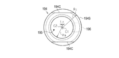
図20A、図20Bに示すように、偏心円筒部材194は、外面として有する半径Rcの円筒面194Sの中心軸C1から所定寸法Lcだけその軸線が平行にずれた中心軸C2を有する半径Raの円形の孔部195を有し、この孔部195に他端側固定軸193が挿通される。そして、円筒面194Sの中心軸C1の軸線方向における2か所に、例えば所謂「イモネジ」などの固定ねじ196が固定部材として取り付けられる。   As shown in FIGS. 20A and 20B, the eccentric cylindrical member 194 has a circular shape with a radius Ra having a central axis C2 whose axis is shifted in parallel by a predetermined dimension Lc from a central axis C1 of a cylindrical surface 194S having a radius Rc as an outer surface. The other end side fixed shaft 193 is inserted into the hole 195. Then, a fixing screw 196 such as a so-called “immo screw” is attached as a fixing member at two positions in the axial direction of the central axis C1 of the cylindrical surface 194S.

固定ねじ196は、本実施形態では、偏心円筒部材194において、円筒面194Sの中心軸C1の軸線に対して、他端側固定軸193が挿入される孔部195の中心軸C2の軸線の位置とは反対の位置に取り付けられる。この結果、固定ねじ196は、偏心円筒部材194において、円筒面194Sの中心軸C1の軸線と交差する面で切断した断面における部材厚が最大となる位置に取り付けられる。また、固定ねじ196は、偏心円筒部材194に回転して取り付けられることによって、孔部195に挿入された他端側固定軸193を、円筒面194Sの中心軸C1の軸線から離れるように孔部195において締め付ける。   In the present embodiment, in the eccentric cylindrical member 194, the fixing screw 196 is located at the position of the axis of the center axis C2 of the hole 195 into which the other end side fixed shaft 193 is inserted with respect to the axis of the center axis C1 of the cylindrical surface 194S. It is attached to the opposite position. As a result, the fixing screw 196 is attached to the eccentric cylindrical member 194 at a position where the member thickness in the cross section cut along a plane intersecting the axis of the central axis C1 of the cylindrical surface 194S is maximized. The fixing screw 196 is rotatably attached to the eccentric cylindrical member 194, so that the other end side fixed shaft 193 inserted into the hole 195 is separated from the axis of the central axis C1 of the cylindrical surface 194S. Tighten at 195.

したがって、孔部195に挿入された他端側固定軸193と孔部195との間に隙間が生じても、偏心円筒部材194に取り付けられる固定ねじ196が他端側固定軸193を締め付けることによって、その隙間は、他端側固定軸193の中心軸に対する偏心円筒部材194の円筒面194Sの中心軸C1のずれ量を多くする。すなわち、固定ねじ196の締め付けは、偏心円筒部材194の他端側固定軸193に対する偏心量を多くするように作用する。   Therefore, even if a gap is formed between the other end side fixed shaft 193 inserted into the hole 195 and the hole 195, the fixing screw 196 attached to the eccentric cylindrical member 194 tightens the other end side fixed shaft 193. The gap increases the amount of deviation of the central axis C1 of the cylindrical surface 194S of the eccentric cylindrical member 194 from the central axis of the other end side fixed shaft 193. That is, the tightening of the fixing screw 196 acts to increase the amount of eccentricity of the eccentric cylindrical member 194 with respect to the other end side fixed shaft 193.

また、本実施形態では、偏心円筒部材194は、この偏心円筒部材194の孔部195に他端側固定軸193が挿入された状態で固定ねじ196が回転され、孔部195において他端側固定軸193が締め付けられることによって、他端側固定軸193に対する円筒面194Sの回動が拘束された状態で固定される。すなわち、本実施形態では、偏心円筒部材194は、他端側固定軸193を中心とする回転トルクが所定のトルク値以上とされた、回動が拘束された状態で、固定ねじ196によって他端側固定軸193に対して取り付けられる。   In the present embodiment, the fixing screw 196 is rotated in a state where the other end side fixing shaft 193 is inserted into the hole 195 of the eccentric cylindrical member 194, and the other end side fixing is performed in the hole 195. By tightening the shaft 193, the rotation of the cylindrical surface 194S with respect to the other end side fixed shaft 193 is fixed and fixed. That is, in the present embodiment, the eccentric cylindrical member 194 is connected to the other end by the fixing screw 196 in a state where the rotation torque about the other end side fixed shaft 193 is set to a predetermined torque value or more and the rotation is restricted. It is attached to the side fixed shaft 193.

したがって、所定のトルク値以上の回転トルクによって他端側固定軸193を中心に強制的に偏心円筒部材194を回転させることが可能であり、回転を停止させた状態において偏心円筒部材194は他端側固定軸193に対して容易に回転しない回転が拘束された状態に維持される。換言すれば、固定ねじ196は、偏心円筒部材194が他端側固定軸193に対して強制的に回転されても、その回転後において回転が拘束された状態が維持されるように、偏心円筒部材194を他端側固定軸193に対して取り付ける。   Therefore, it is possible to forcibly rotate the eccentric cylindrical member 194 about the other end side fixed shaft 193 by a rotation torque equal to or more than a predetermined torque value, and in the state where the rotation is stopped, the eccentric cylindrical member 194 is connected to the other end. The rotation that does not easily rotate with respect to the side fixed shaft 193 is maintained in a restricted state. In other words, even if the eccentric cylindrical member 194 is forcibly rotated with respect to the other end side fixed shaft 193, the fixing screw 196 is configured to maintain the rotation-restricted state after the rotation. The member 194 is attached to the other end side fixed shaft 193.

そして、本実施形態では、偏心円筒部材194が他端側固定軸193に取り付けられた状態で、偏心円筒部材194を回転させるため、偏心円筒部材194には、円筒面194Sの少なくとも一部に、円筒面194Sの中心軸C1の軸線と平行なカット面194Cが少なくとも一つ設けられている。具体的に、本実施形態では、カット面194Cは、円筒面194Sにおいて、固定ねじ196を挟んだ両側であって、移動方向Aの上側端部において、互いに平行となるように一対設けられている。したがって、このカット面194Cをスパナなどの工具で挟んで偏心円筒部材194を強制的に回転させることが可能であり、この偏心円筒部材194を強制的に回転させることによって、記録部118の傾き調節が行われる。   In the present embodiment, the eccentric cylindrical member 194 is rotated in a state where the eccentric cylindrical member 194 is attached to the other end side fixed shaft 193. Therefore, the eccentric cylindrical member 194 has at least a part of the cylindrical surface 194S. At least one cut surface 194C parallel to the axis of the central axis C1 of the cylindrical surface 194S is provided. Specifically, in the present embodiment, a pair of cut surfaces 194C is provided on both sides of the cylindrical surface 194S with the fixing screw 196 interposed therebetween and at the upper end in the movement direction A so as to be parallel to each other. . Therefore, it is possible to forcibly rotate the eccentric cylindrical member 194 by sandwiching the cut surface 194C with a tool such as a wrench. By forcibly rotating the eccentric cylindrical member 194, the inclination of the recording unit 118 can be adjusted. Is performed.

次に、図21A、図21Bを参照して、記録部118の傾き調節について説明する。なお、ここで参照する図21A、図21Bは、説明を解りやすくするため、符号を付した各構成部材について模式化されて図示されている。   Next, the tilt adjustment of the recording unit 118 will be described with reference to FIGS. 21A and 21B. 21A and 21B that are referred to here are schematically illustrated with respect to each of the component members that are denoted by reference numerals for easy understanding.

図21Aに示すように、記録部118が、駆動ローラー134aによって搬送される用紙114の搬送方向Yと交差(ここでは直交)する幅方向Xから、他端側(+X側)が一端側(−X側)に対して搬送方向Yの上流側に位置する斜め状態に傾いている場合であるとする。このような場合、液体吐出ヘッド170に形成されたノズルNの幅方向Xにおける間隔が不揃いになる状態が生じる。   As shown in FIG. 21A, the other end (+ X side) is one end side (−X side) from the width direction X where the recording unit 118 crosses (here, orthogonal to) the conveyance direction Y of the paper 114 conveyed by the drive roller 134a. It is assumed that the case is inclined to an oblique state located on the upstream side in the transport direction Y with respect to the (X side). In such a case, there occurs a state where the intervals in the width direction X of the nozzles N formed in the liquid ejection head 170 are not uniform.

すなわち、搬送方向Yから見た各ノズルNの幅方向Xにおける間隔は均一ではなく、例えば図21AにおいてノズルNaとノズルNbに示すように、ノズル列NR間に位置する2つのノズルNの間隔が、ノズル列NR内でのノズルNの間隔よりも狭くなってしまう。あるいは、ここでは図示を省略するが、記録部118が、幅方向Xから、他端側(+X側)が一端側(−X側)に対して搬送方向Yの下流側に位置する斜め状態に傾いている場合は、ノズル列NR間に位置する2つのノズルNの間隔が、ノズル列NR内でのノズルNの間隔よりも広くなってしまう。このため、例えば記録部118によって用紙114に記録された画像に黒スジ(あるいは白スジ)などが発生し、記録品質の低下を招く虞がある。   That is, the interval between the nozzles N in the width direction X viewed from the transport direction Y is not uniform. For example, as shown in the nozzles Na and the nozzles Nb in FIG. , Becomes smaller than the interval between the nozzles N in the nozzle row NR. Alternatively, although not shown here, the recording unit 118 is in an oblique state in which the other end (+ X side) is positioned downstream of the one end (−X side) in the transport direction Y from the width direction X. When the nozzles are inclined, the interval between the two nozzles N located between the nozzle rows NR becomes wider than the interval between the nozzles N in the nozzle row NR. For this reason, for example, black streaks (or white streaks) may occur in the image recorded on the sheet 114 by the recording unit 118, which may cause a decrease in recording quality.

そこで、図21Bに示すように、記録部118の長手方向が、駆動ローラー134aによって搬送される用紙114の搬送方向Yに対して直交する幅方向Xとなるように、記録部118の傾きを補正する。   Therefore, as shown in FIG. 21B, the inclination of the recording unit 118 is corrected so that the longitudinal direction of the recording unit 118 is in the width direction X orthogonal to the transport direction Y of the paper 114 transported by the drive roller 134a. I do.

すなわち、他端側貫通孔152に挿入された他端側挿入軸192において、他端側固定軸193に対して偏心円筒部材194を回転させる。一例として、偏心円筒部材194を、図21Aにおいて網掛けで示す位置から、白抜き矢印で示すように紙面の表側から見て時計回り方向へ回転させる。この回転により偏心円筒部材194は、図21Bにおいて網掛けで示す位置へ移動し、記録部118の他端側(+X側)を、他端側固定軸193を基準として、最大で、他端側固定軸193の中心軸からの偏心量分、搬送方向Yの下流側へ移動させる。   That is, the eccentric cylindrical member 194 is rotated with respect to the other end side fixed shaft 193 in the other end side insertion shaft 192 inserted into the other end side through hole 152. As an example, the eccentric cylindrical member 194 is rotated clockwise as viewed from the front side of the paper as indicated by a white arrow from the hatched position in FIG. 21A. By this rotation, the eccentric cylindrical member 194 moves to a position shown by hatching in FIG. 21B, and the other end (+ X side) of the recording unit 118 is moved up to the other end with respect to the other end fixed shaft 193. The fixed shaft 193 is moved to the downstream side in the transport direction Y by the amount of eccentricity from the central axis.

このとき、記録部118の一端側(−X側)は、一端側貫通孔151に挿入された一端側挿入軸191によって搬送方向Yおよび幅方向Xの双方において位置決めされている。このため、記録部118は、一端側挿入軸191を回転の中心軸(基準軸)として回転(揺動)する。したがって、偏心円筒部材194の回転量を調節することによって、記録部118の他端側(+X側)の搬送方向Yに沿う移動量を調節することができる。この調節された移動量に応じて、記録部118は一端側挿入軸191を中心に回転(揺動)し、用紙114の搬送方向Yと直交する幅方向Xに対する記録部118の長手方向の傾きが調節される。   At this time, one end (−X side) of the recording unit 118 is positioned in both the transport direction Y and the width direction X by the one end insertion shaft 191 inserted into the one end through hole 151. For this reason, the recording unit 118 rotates (oscillates) with the one end side insertion shaft 191 as a rotation center axis (reference axis). Therefore, by adjusting the amount of rotation of the eccentric cylindrical member 194, it is possible to adjust the amount of movement of the other end side (+ X side) of the recording unit 118 along the transport direction Y. In accordance with the adjusted amount of movement, the recording unit 118 rotates (oscillates) about the one end insertion shaft 191, and tilts in the longitudinal direction of the recording unit 118 with respect to the width direction X orthogonal to the transport direction Y of the paper 114. Is adjusted.

このように記録部118の長手方向の傾きを調節することができるので、偏心円筒部材194を記録部118の外縁と当接させる構成を採用する必要はなく、偏心円筒部材194を配置するスペースを省スペース化することができる。そして、記録部118の長手方向が搬送方向Yと直交する幅方向Xと一致した場合、液体吐出ヘッド170に形成されたノズルNの幅方向Xにおける間隔が均一になる。例えば、図21BにおいてノズルNaとノズルNbに示すように、搬送方向Yから見た各ノズルNの幅方向Xにおける各間隔において、ノズル列NR間に位置する2つのノズルNの間隔と、ノズル列NR内での各ノズルNの間隔とが等しくなる。このため、例えば記録部118によって用紙114に記録された画像において白スジや黒スジなどの発生を抑制する。   Since the inclination of the recording unit 118 in the longitudinal direction can be adjusted in this manner, there is no need to employ a configuration in which the eccentric cylindrical member 194 is in contact with the outer edge of the recording unit 118, and the space for disposing the eccentric cylindrical member 194 is reduced. Space can be saved. When the longitudinal direction of the recording unit 118 coincides with the width direction X orthogonal to the transport direction Y, the intervals in the width direction X of the nozzles N formed on the liquid ejection head 170 become uniform. For example, as shown by the nozzle Na and the nozzle Nb in FIG. 21B, at each interval in the width direction X of each nozzle N viewed from the transport direction Y, an interval between two nozzles N located between the nozzle rows NR, The interval between the nozzles N in NR becomes equal. For this reason, for example, the occurrence of white stripes or black stripes in the image recorded on the sheet 114 by the recording unit 118 is suppressed.

なお、液体吐出ヘッド170に形成されたノズルNの幅方向Xにおける間隔が均一になるように、記録部118の傾きを調節した状態において、必ずしも記録部118の長手方向が搬送方向Yと直交する幅方向Xと一致していなくても差し支えない。   Note that, in a state where the inclination of the recording unit 118 is adjusted such that the intervals in the width direction X of the nozzles N formed in the liquid ejection head 170 are uniform, the longitudinal direction of the recording unit 118 is necessarily perpendicular to the transport direction Y. It does not matter if it does not coincide with the width direction X.

また、本実施形態の他の作用として、支持台117上を搬送される用紙114の記録面114Pと記録部118の液体吐出ヘッド170との間の距離(隙間)が、軸受移動機構によって幅方向Xに沿って均一な状態、すなわち平行状態に調節される際に、記録部118を円滑に移動させる移動作用を有している。   Further, as another operation of the present embodiment, the distance (gap) between the recording surface 114P of the sheet 114 conveyed on the support stand 117 and the liquid ejection head 170 of the recording unit 118 is changed by the bearing moving mechanism in the width direction. When adjusted to a uniform state, that is, a parallel state along X, the recording unit 118 has a movement function of smoothly moving the recording unit 118.

図22A、図22Bを参照して、この移動作用について説明する。なお、ここで参照する図22A、図22Bは、説明を解りやすくするため、符号を付した各構成部材は模式化されて図示されている。   This moving operation will be described with reference to FIGS. 22A and 22B. In FIG. 22A and FIG. 22B to which reference is made herein, for the sake of easy understanding, the constituent members given reference numerals are schematically illustrated.

図22Aに示すように、記録部118が、支持台117上を搬送される用紙114の記録面114Pに対して、搬送方向Yと交差(直交)する幅方向Xにおいて、一端側(−X側)が他端側(+X側)よりも下がって記録面114P側に近づいた斜め状態で傾いている場合であるとする。このような場合、液体吐出ヘッド170から吐出されたインク(不図示)は、一端側(−X側)の方が他端側(+X側)よりも早く記録面114Pに到達するため、この記録面114Pへの到達までの時間差に起因して記録面114Pに印刷される画像に歪が生じる虞がある。そこで、図22A、図22Bに示すように、記録部118の一端側(−X側)の調節ねじ169Aを回して一端側の軸受169を基台部199に対して上昇させ、一端側の軸受169に軸支された回動軸163の一端側を上昇させる。   As shown in FIG. 22A, the recording unit 118 is positioned on one end side (−X side) in the width direction X that intersects (perpendicularly) with the conveyance direction Y with respect to the recording surface 114 </ b> P of the sheet 114 conveyed on the support stand 117. ) Is lower than the other end (+ X side) and is inclined in an oblique state approaching the recording surface 114P side. In such a case, the ink (not shown) ejected from the liquid ejection head 170 reaches the recording surface 114P at one end (−X side) earlier than at the other end (+ X side). There is a possibility that an image printed on the recording surface 114P may be distorted due to a time difference until the image reaches the surface 114P. Therefore, as shown in FIGS. 22A and 22B, the adjustment screw 169A on one end side (−X side) of the recording unit 118 is turned to raise the bearing 169 on one end side with respect to the base 199, and the bearing on one end side is rotated. The one end of the rotation shaft 163 supported by the shaft 169 is raised.

この結果、図22Bに示すように、回動軸163が上昇することによって、回動軸163に設けられた一端側のカム165が従節部158を介して記録部118の一端側を移動方向Aに沿って上方へ移動させる。この一端側が上昇することによって、記録部118は用紙114(支持台117)と幅方向Xにおいて平行となるように調節される。   As a result, as shown in FIG. 22B, when the rotating shaft 163 is raised, the cam 165 on one end provided on the rotating shaft 163 moves one end of the recording unit 118 via the follower 158 in the moving direction. Move upward along A. By raising this one end side, the recording unit 118 is adjusted so as to be parallel to the sheet 114 (the support table 117) in the width direction X.

このとき、記録部118は筒部153に設けられた第1ブッシュ155の円形の第1貫通孔151Aと、この第1貫通孔に対して僅かな隙間を有して挿入された一端側挿入軸191と、によって搬送方向Y及び幅方向Xの双方が位置決めされた状態で、記録部118の一端側の上方へ移動する。このために、記録部118は、相対的に、第1ブッシュ155を中心にして、搬送方向Yの上流側から見て時計回り方向へ回転することになる。この記録部118の第1ブッシュ155を中心とする時計回り方向への回転に伴って、筒部153に設けられた第2ブッシュ156は記録部118の長手方向における他端側(+X側)の方向へ向かって移動するとともに、平板部154に設けられた他端側貫通孔152も記録部118の長手方向における他端側(+X側)の方向へ向かって移動する。   At this time, the recording unit 118 has a circular first through hole 151A of the first bush 155 provided in the cylindrical portion 153, and one end side insertion shaft inserted with a slight gap with respect to the first through hole. 191, the recording unit 118 is moved upward at one end side in a state where both the conveying direction Y and the width direction X are positioned. Therefore, the recording unit 118 relatively rotates clockwise around the first bush 155 as viewed from the upstream side in the transport direction Y. With the clockwise rotation of the recording section 118 around the first bush 155, the second bush 156 provided on the cylindrical section 153 is located at the other end (+ X side) in the longitudinal direction of the recording section 118. Along with the other direction, the other end side through hole 152 provided in the flat plate portion 154 also moves toward the other end side (+ X side) in the longitudinal direction of the recording section 118.

このとき、第2ブッシュ156の第2貫通孔151Bが記録部118の長手方向(幅方向X)に沿う平行縁部L3を有する長円形孔とされているので、第2ブッシュ156は、第2貫通孔151Bと、この第2貫通孔151Bに挿入されている一端側挿入軸191との間での抉りが発生することなく、円滑に移動する。また、他端側貫通孔152も記録部118の長手方向(幅方向X)に沿う平行縁部L2を有する長円形孔とされているので、他端側貫通孔152が設けられた記録部118の平板部154は、他端側貫通孔152と、この他端側貫通孔152に挿入されている他端側挿入軸192との間での抉りが発生することなく、円滑に移動する。   At this time, since the second through-hole 151B of the second bush 156 is an elliptical hole having a parallel edge L3 along the longitudinal direction (the width direction X) of the recording unit 118, the second bush 156 has the second shape. The hole 151B smoothly moves without a gouge between the through hole 151B and the one end side insertion shaft 191 inserted into the second through hole 151B. Further, since the other end side through hole 152 is also an oval hole having a parallel edge portion L2 along the longitudinal direction (width direction X) of the recording unit 118, the recording unit 118 provided with the other end side through hole 152 is provided. The flat plate portion 154 moves smoothly without a gouge between the other end side through hole 152 and the other end side insertion shaft 192 inserted into the other end side through hole 152.

なお、第2貫通孔151Bおよび他端側貫通孔152のそれぞれの長手方向(幅方向X)に沿う平行縁部の長さは、軸受移動機構によって幅方向Xに沿って均一な状態(平行状態)に調節される際に、記録部118を円滑に移動させることができる長さに設定される。   The length of the parallel edge portion along the longitudinal direction (width direction X) of each of the second through-hole 151B and the other end side through-hole 152 is uniform (parallel state) along the width direction X by the bearing moving mechanism. The length is set to a length that allows the recording unit 118 to move smoothly when the adjustment is made to ()).

上記実施形態によれば、以下に示す効果を得ることができる。
(1)記録部118の長手方向の両側の略三角形領域R(図18参照)において、一端側貫通孔151および他端側貫通孔152を、それぞれ形成するようにしたので、記録部118の外形を長手方向や短手方向へ延ばしてその形状を大きくすることなく、記録部118の長手方向の傾きを調節する機構を配置することができる。
According to the above embodiment, the following effects can be obtained.
(1) One end side through-hole 151 and the other end side through-hole 152 are formed in the substantially triangular regions R (see FIG. 18) on both sides in the longitudinal direction of the recording unit 118. A mechanism that adjusts the inclination of the recording unit 118 in the longitudinal direction can be provided without extending the shape of the recording unit 118 in the longitudinal direction or the lateral direction.

また、記録部118を付勢部材によって付勢することなく、貫通孔と、その貫通孔に挿入された挿入軸(例えば偏心円筒部材194)とによって、搬送部115により搬送される用紙114の搬送方向Yと直交する幅方向Xに対する記録部118の傾きを補正する。この結果、貫通孔および挿入軸の摩耗が抑制され、記録部118の傾き補正を適切に行うことができるので、記録品質(例えば画質)の低下を抑制することができる。また、付勢部材に起因する記録部118の振動が生じないので、記録品質の低下を抑制することができる。   Also, the paper 114 conveyed by the conveyance unit 115 is conveyed by the through hole and the insertion shaft (for example, the eccentric cylindrical member 194) inserted into the through hole without urging the recording unit 118 with the urging member. The inclination of the recording unit 118 with respect to the width direction X orthogonal to the direction Y is corrected. As a result, abrasion of the through-hole and the insertion shaft is suppressed, and the inclination of the recording unit 118 can be properly corrected, so that a decrease in recording quality (for example, image quality) can be suppressed. Further, since the recording section 118 does not vibrate due to the urging member, it is possible to suppress a decrease in recording quality.

(2)固定ねじ196によって他端側固定軸193に偏心円筒部材194を固定する際に、その偏心量が小さくならないように抑制することができるので、記録部118の傾き補正を適切に行うことができる。   (2) When the eccentric cylindrical member 194 is fixed to the other end side fixed shaft 193 by the fixing screw 196, the amount of eccentricity can be suppressed so as not to be small, so that the inclination correction of the recording unit 118 is appropriately performed. Can be.

(3)設けられたカット面194Cによって、他端側固定軸193に偏心円筒部材194を固定する際に、偏心円筒部材194の他端側固定軸193に対する回転位置を容易に判別することができるので、記録部118の傾き補正を適切に行うことができる。また、カット面194Cを用いることによって偏心円筒部材194を他端側固定軸193回りに容易に回転させることができる。   (3) When the eccentric cylindrical member 194 is fixed to the other end fixed shaft 193 by the provided cut surface 194C, the rotational position of the eccentric cylindrical member 194 with respect to the other end fixed shaft 193 can be easily determined. Therefore, the inclination correction of the recording unit 118 can be appropriately performed. Further, by using the cut surface 194C, the eccentric cylindrical member 194 can be easily rotated around the other end side fixed shaft 193.

(4)一端側挿入軸191および他端側挿入軸192は記録部118を移動方向Aに沿って移動させる際に記録部118の移動を案内するので、記録部118を用紙114の記録面114Pに対して相対的に移動させる際の案内軸を別途設ける必要がない。したがって、プリンター111の構造が複雑化することを抑制することができる。   (4) The one end side insertion shaft 191 and the other end side insertion shaft 192 guide the movement of the recording unit 118 when moving the recording unit 118 along the movement direction A. There is no need to separately provide a guide shaft for moving the guide shaft relative to. Therefore, the structure of the printer 111 can be prevented from becoming complicated.

(5)記録部118を用紙114の記録面114Pに対して平行となるように調節する場合、移動方向Aへの記録部118の移動量が長手方向の両端部において異なる場合であっても、一端側挿入軸191が長円形孔の第2貫通孔151Bにおいて抉られることなく円滑に移動することができる。   (5) When the recording unit 118 is adjusted so as to be parallel to the recording surface 114P of the sheet 114, even if the moving amount of the recording unit 118 in the moving direction A is different at both ends in the longitudinal direction, The one end side insertion shaft 191 can smoothly move without being dug out in the second through hole 151B of the oval hole.

(6)一端側挿入軸191および他端側固定軸193が固定された基台部199の部分と、軸受部199Jが設けられた基台部199の部分とは一体であるので、駆動ローラー134aによる用紙114の搬送方向Yに対して、一端側挿入軸191および他端側挿入軸192(他端側固定軸193)の位置ずれが抑制される。したがって、駆動ローラー134aにより搬送される用紙114に対して、搬送方向Yと直交する幅方向Xに対する傾きを精度良く調節することができる。   (6) The part of the base part 199 to which the one end side insertion shaft 191 and the other end side fixed shaft 193 are fixed and the part of the base part 199 provided with the bearing part 199J are integral with each other. , The displacement of the one-end insertion shaft 191 and the other-end insertion shaft 192 (the other-end fixed shaft 193) with respect to the transport direction Y of the paper 114 is suppressed. Therefore, the inclination of the sheet 114 conveyed by the drive roller 134a with respect to the width direction X orthogonal to the conveyance direction Y can be adjusted with high accuracy.

(7)一端側挿入軸191および他端側挿入軸192は、キャップ172を記録部118に対して位置決めするので、キャップ172が記録部118を覆う際の記録部118に対する位置決め部材を別途設ける必要がない。したがって、プリンター111の構造が複雑化することを抑制することができる。   (7) Since the one end side insertion shaft 191 and the other end side insertion shaft 192 position the cap 172 with respect to the recording unit 118, it is necessary to separately provide a positioning member for the recording unit 118 when the cap 172 covers the recording unit 118. There is no. Therefore, the structure of the printer 111 can be prevented from becoming complicated.

なお、上記実施形態は、以下のような別の実施形態に変更してもよい。
・上記実施形態において、他端側挿入軸192は、キャップ172が記録部118を覆う際に、偏心円筒部材194によって、キャップ172を記録部118に対して位置決めすることが好ましい。このキャップ172の位置決め構造の変形例について図を参照して説明する。
The above embodiment may be changed to another embodiment as described below.
In the above embodiment, when the cap 172 covers the recording unit 118, the other end side insertion shaft 192 preferably positions the cap 172 with respect to the recording unit 118 by the eccentric cylindrical member 194. A modification of the positioning structure of the cap 172 will be described with reference to the drawings.

図23A、図23Bに示すように、本変形例の偏心円筒部材194は、外面の円筒面194Sの中心軸と同じ中心軸を有し、基台部199の用紙114側となる下側に位置するように設けられた円柱部材198が、略C字形の連結部197によって偏心円筒部材194の円筒面194Sと繋がれている。そして、偏心円筒部材194の孔部195に挿入された他端側固定軸193は、上記実施形態における他端側軸突出部193A(図13参照)が設けられることなく、基台部199に設けられた略半円形の庇部199Hに固定されている。   As shown in FIGS. 23A and 23B, the eccentric cylindrical member 194 of this modification has the same central axis as the central axis of the outer cylindrical surface 194S, and is located on the lower side of the base portion 199 on the paper 114 side. The cylindrical member 198 provided so as to be connected to the cylindrical surface 194S of the eccentric cylindrical member 194 by a substantially C-shaped connecting portion 197. The other end side fixed shaft 193 inserted into the hole 195 of the eccentric cylindrical member 194 is provided on the base 199 without providing the other end side shaft protrusion 193A (see FIG. 13) in the above embodiment. Is fixed to the substantially semicircular eave portion 199H.

また、偏心円筒部材194の連結部197は、偏心円筒部材194がカット面194Cを用いて回転させられたとき、図23Bにおいて二点鎖線で示すように、基台部199に設けられた庇部199Hの略半円形の外周に沿って約半周分、回転可能に形成されている。この結果、この連結部197によって繋がれた円柱部材198は、記録部118の傾き調節において偏心円筒部材194が回転させられる際、偏心円筒部材194と一緒に他端側固定軸193を中心に回転する。この結果、円柱部材198は、図23Bにおいて二点鎖線で示すように、搬送方向Yにおいて移動する。   Further, when the eccentric cylindrical member 194 is rotated using the cut surface 194C, the connecting portion 197 of the eccentric cylindrical member 194 is provided with an eave portion provided on the base 199 as shown by a two-dot chain line in FIG. 23B. It is formed to be rotatable by about a half circumference along the substantially semicircular outer circumference of 199H. As a result, the cylindrical member 198 connected by the connecting portion 197 rotates together with the eccentric cylindrical member 194 about the other end side fixed shaft 193 when the eccentric cylindrical member 194 is rotated in adjusting the inclination of the recording unit 118. I do. As a result, the cylindrical member 198 moves in the transport direction Y as shown by a two-dot chain line in FIG. 23B.

そこで、本変形例では、記録部118に対するキャップ172の位置決めを、他端側軸突出部193Aに替えて、偏心円筒部材194の円筒面の中心軸と同一の中心軸を有する円柱部材198によって行うようにする。すなわち、キャップ172が記録部118を覆う際に、キャップ172の他端側延設部175に設けられた他端側穴部175Aに円柱部材198が挿入することによって、偏心円筒部材194の回転によって搬送方向Yにおける傾きが調節された記録部118に対して、その回転後の偏心円筒部材194の円筒面194Sの中心に合わせてキャップ172が位置決めされる。   Therefore, in this modification, the positioning of the cap 172 with respect to the recording unit 118 is performed by the cylindrical member 198 having the same central axis as the central axis of the cylindrical surface of the eccentric cylindrical member 194 instead of the other end side shaft projection 193A. To do. That is, when the cap 172 covers the recording section 118, the cylindrical member 198 is inserted into the other end side hole 175 </ b> A provided in the other end side extension 175 of the cap 172, whereby the eccentric cylindrical member 194 rotates. The cap 172 is positioned with respect to the center of the cylindrical surface 194S of the rotated eccentric cylindrical member 194 with respect to the recording unit 118 whose inclination in the transport direction Y is adjusted.

なお、円柱部材198は、図23Bにおいて二点鎖線で示すように、搬送方向Yにおいて移動するとともに、幅方向Xにおいても移動する。したがって、円柱部材198が挿入する他端側延設部175に設けられる他端側穴部175Aは、他端側貫通孔152と同様に、キャップ172の長手方向(幅方向X)に沿う直線状の平行縁部を有する長孔とされることが好ましい。   Note that the cylindrical member 198 moves in the transport direction Y and also moves in the width direction X, as indicated by the two-dot chain line in FIG. 23B. Therefore, like the other end side through hole 152, the other end side hole 175A provided in the other end side extension 175 into which the cylindrical member 198 is inserted has a linear shape along the longitudinal direction (width direction X) of the cap 172. It is preferable to form a long hole having a parallel edge portion.

この変形例によれば、上記実施形態の効果(1)〜(7)に加えて次の効果を奏する。
(8)キャップ172が記録部118を覆う際の記録部118に対する位置決めを、傾きが調節された記録部118の位置に合わせて行うことができるので、キャップ172は記録部118に対する位置ずれが抑制された状態で記録部118を覆うことができる。
According to this modification, the following effects are obtained in addition to the effects (1) to (7) of the above-described embodiment.
(8) Since the positioning of the cap 172 with respect to the recording unit 118 when covering the recording unit 118 can be performed in accordance with the position of the recording unit 118 whose inclination has been adjusted, the displacement of the cap 172 with respect to the recording unit 118 is suppressed. In this state, the recording unit 118 can be covered.

・上記実施形態において、必ずしも一端側挿入軸191および他端側挿入軸192は、キャップ172が記録部118を覆う際に、当該キャップ172を記録部118に対して位置決めしなくてもよい。例えば、キャップ172の位置決めは別途設けられた位置決め部材によって行われるようにしてもよい。もとより、キャップ172が備えられていない場合は、キャップ172の位置決めは不要である。   In the above embodiment, when the cap 172 covers the recording unit 118, the one-end insertion shaft 191 and the other-end insertion shaft 192 do not necessarily need to position the cap 172 relative to the recording unit 118. For example, the positioning of the cap 172 may be performed by a separately provided positioning member. Of course, when the cap 172 is not provided, the positioning of the cap 172 is unnecessary.

・上記実施形態では、記録部118が備える液体吐出ヘッド170は、その長手方向(幅方向X)の両端が、長手方向と直交する方向から傾いた斜辺を有する略平行四辺形の外形形状とされた複数(ここでは6つ)の個別ヘッドを記録部118の長手方向に沿って併設した構成としたが、これに限るものではない。   In the above-described embodiment, the liquid discharge head 170 provided in the recording unit 118 has a substantially parallelogram outer shape having oblique sides inclined at both ends in the longitudinal direction (width direction X) from a direction orthogonal to the longitudinal direction. Although a plurality of (six in this case) individual heads are arranged along the longitudinal direction of the recording unit 118, the present invention is not limited to this.

図24A〜図24Dに示す模式図を参照して、本変形例を説明する。
図24Aに示した上記実施形態の液体吐出ヘッド170、一端側貫通孔151、他端側貫通孔152に対して、図24Bに示すように、記録部118が備える液体吐出ヘッド170は、各液体吐出ヘッド170が千鳥に配置される千鳥配置であっても良い。この場合には、三角形領域Rではなく、記録部118の長手方向の両側の図24Bに示す矩形領域Kにおいて、一端側貫通孔151および他端側貫通孔152を、それぞれ形成するようにする。
これにより、同様に記録部118の傾き補正を行うための機構を配置するスペースを省スペース化して、プリンター111の大型化を抑制することができる。
This modification will be described with reference to the schematic diagrams shown in FIGS. 24A to 24D.
As shown in FIG. 24B, the liquid ejection head 170 provided in the recording unit 118 is different from the liquid ejection head 170, the one end through-hole 151, and the other end through-hole 152 of the embodiment shown in FIG. A staggered arrangement in which the ejection heads 170 are staggered may be used. In this case, one end side through hole 151 and the other end side through hole 152 are formed not in the triangular region R but in the rectangular region K shown in FIG. 24B on both sides in the longitudinal direction of the recording unit 118.
As a result, the space for disposing the mechanism for correcting the inclination of the recording unit 118 can be saved, and the printer 111 can be prevented from being enlarged.

また、図24C、図24Dに示すように、他端側貫通孔152のみを三角形領域Rもしくは矩形領域Kに形成するようにしても良い。さらに、一端側貫通孔151のみを三角形領域Rもしくは矩形領域Kに形成するようにしても良いことは言うまでもない。これにより、同様にプリンター111が大型化することを抑制するという効果を得ることができる。   Further, as shown in FIGS. 24C and 24D, only the other end side through hole 152 may be formed in the triangular region R or the rectangular region K. Further, it goes without saying that only the one end side through hole 151 may be formed in the triangular region R or the rectangular region K. Thus, the effect of suppressing the printer 111 from increasing in size can be obtained.

・上記実施形態において、一端側固定軸である一端側挿入軸191、および他端側固定軸193がそれぞれ固定された基台部199の部分と、駆動ローラー134aの軸受部199Jが設けられた基台部199の部分とは、必ずしも一体でなくてもよい。例えば、駆動ローラー134aによって搬送される用紙114に対する位置ズレが抑制された状態で一端側挿入軸191および他端側固定軸193が固定される構造であれば、一端側挿入軸191および他端側固定軸193が固定された基台部199の部分と、駆動ローラー134aの軸受部199Jが設けられた基台部199の部分とは別体であってもよい。   In the above-described embodiment, the base provided with the base portion 199 to which the one end side insertion shaft 191 and the other end side fixed shaft 193 are fixed, and the bearing portion 199J of the drive roller 134a are provided. The portion of the base 199 does not necessarily have to be integrated. For example, if the one end side insertion shaft 191 and the other end side fixed shaft 193 are fixed in a state where the positional deviation with respect to the sheet 114 conveyed by the driving roller 134a is suppressed, the one end side insertion shaft 191 and the other end side The portion of the base portion 199 to which the fixed shaft 193 is fixed may be separate from the portion of the base portion 199 provided with the bearing portion 199J of the drive roller 134a.

・上記実施形態において、一端側挿入軸191が挿入される一端側貫通孔151は、第1貫通孔151Aのみとし、第2貫通孔151Bを備えない構成であってもよい。例えば、第1貫通孔151Aの記録部118の移動方向Aにおける長さを長くすることによって記録部118を移動方向Aに沿って安定して移動させる構成としてもよい。あるいは、例えば記録部118を搬送方向Yの両側において挟むように支持する支持部材を別途設けて、記録部118が移動方向Aに沿って円滑に移動できる構成としてもよい。   In the above embodiment, the one end side through hole 151 into which the one end side insertion shaft 191 is inserted may be configured to include only the first through hole 151A and not include the second through hole 151B. For example, the recording unit 118 may be stably moved in the moving direction A by increasing the length of the first through hole 151A in the moving direction A of the recording unit 118. Alternatively, for example, a support member that supports the recording unit 118 so as to sandwich the recording unit 118 on both sides in the transport direction Y may be separately provided, so that the recording unit 118 can move smoothly along the movement direction A.

・上記実施形態において、一端側挿入軸191および他端側挿入軸192は、必ずしも、移動部160が記録部118を移動方向Aに沿って移動させる際に記録部118の移動を案内する案内軸でなくてもよい。すなわち、記録部118の移動を案内する案内軸は、一端側挿入軸191および他端側挿入軸192とは別に設けてもよい。   In the above embodiment, the one end side insertion shaft 191 and the other end side insertion shaft 192 are not necessarily guide shafts for guiding the movement of the recording unit 118 when the moving unit 160 moves the recording unit 118 along the movement direction A. It does not have to be. That is, the guide shaft for guiding the movement of the recording unit 118 may be provided separately from the one-end insertion shaft 191 and the other-end insertion shaft 192.

・上記実施形態において、偏心円筒部材194は、必ずしも、円筒面194Sの少なくとも一部に、円筒面194Sの中心軸線と平行なカット面194Cが設けられなくてもよい。例えば、円筒面194Sが、工具によって挟んで回すことによって偏心円筒部材194を回転させることが可能な面であれば、カット面は不要である。例えば、円筒面194Sの少なくとも一部において凹凸面を形成して工具との間の摩擦係数を大きくすることによって、工具によって挟まれる部分がすべり難くなるようにしてもよい。   -In the said embodiment, the eccentric cylindrical member 194 does not necessarily need to provide the cut surface 194C parallel to the central axis of the cylindrical surface 194S in at least one part of the cylindrical surface 194S. For example, if the cylindrical surface 194S is a surface that can rotate the eccentric cylindrical member 194 by being pinched and rotated by a tool, a cut surface is unnecessary. For example, an uneven surface may be formed on at least a part of the cylindrical surface 194S to increase the coefficient of friction between the tool and the tool, so that the portion sandwiched by the tool is less likely to slip.

・上記実施形態において、偏心円筒部材194の固定部材となる固定ねじ196は、偏心円筒部材194において、必ずしも円筒面194Sの中心軸C1の軸線に対して他端側固定軸193の中心軸線の位置とは反対の位置に取り付けられなくてもよい。偏心円筒部材194の他端側固定軸193に対する回転が拘束される位置であれば、固定ねじ196は、どのような位置に取り付けられてもよい。また、固定ねじ196の本数も必ずしも2本に限らず、1本でもよいし、2本より多くてもよい。   In the above embodiment, the fixing screw 196 serving as the fixing member of the eccentric cylindrical member 194 is not necessarily the position of the center axis of the other end side fixed shaft 193 with respect to the axis of the center axis C1 of the cylindrical surface 194S in the eccentric cylindrical member 194. It does not need to be attached to the opposite position. The fixing screw 196 may be attached to any position as long as the rotation of the eccentric cylindrical member 194 with respect to the other end side fixed shaft 193 is restricted. The number of fixing screws 196 is not necessarily limited to two, and may be one or more than two.

・上記実施形態において、一端側貫通孔151である第2貫通孔151B、および他端側貫通孔152は、必ずしも、一対の平行縁部とその両端が半円縁部の長円形状の長孔でなくてもよい。例えば、記録部118の長手方向に沿って、その長手方向を有する矩形の長孔であってもよい。要は、記録部118の長手方向と交差(直交)する短手方向において、貫通孔に挿入される挿入軸の外径(直径)寸法と略同じ大きさの幅寸法を有する部分が、記録部118の長手方向において、傾き調節時や平行状態の調節時などにおいて軸が抉られない所定長さを有する形状であればよい。   In the above embodiment, the second through-hole 151B, which is one end-side through-hole 151, and the other end-side through-hole 152 are not necessarily a pair of parallel edges and both ends of which are semi-circular ellipses. It does not have to be. For example, a rectangular slot having the longitudinal direction along the longitudinal direction of the recording unit 118 may be used. In short, a portion having a width substantially the same as the outer diameter (diameter) of the insertion shaft inserted into the through hole in the short direction crossing (perpendicular to) the longitudinal direction of the recording unit 118 is formed by In the longitudinal direction of 118, any shape may be used as long as the shaft has a predetermined length so that the shaft is not dug when adjusting the tilt or adjusting the parallel state.

・上記実施形態において、一端側貫通孔151は、必ずしも、液体吐出ヘッド170の内の、最も記録部118の長手方向における一方の端部の側に近い液体吐出ヘッド170(個別ヘッド)と、記録部118の搬送方向Yにおいて重なるように配置しなくてもよい。例えば、一端側貫通孔151は、記録部118の傾き補正を行う際の記録部118の回転の中心軸(基準軸)であるので、軸を細くして省スペース化を図るようにしてもよい。   In the above-described embodiment, the one end side through-hole 151 is not necessarily the liquid ejection head 170 (individual head) closest to one end of the liquid ejection head 170 in the longitudinal direction of the recording unit 118. It is not necessary to arrange them so as to overlap in the transport direction Y of the section 118. For example, the one end side through hole 151 is a central axis (reference axis) of the rotation of the recording unit 118 when the inclination of the recording unit 118 is corrected, so that the axis may be narrowed to save space. .

・上記実施形態において、記録部118から吐出する記録液であるインクの供給元は、例えばプリンター111の筐体112の内部に設けられるインク収容体であってもよい。あるいは、筐体112の外部に設けられる所謂外付けタイプのインク収容体であってもよい。特に外付けタイプのインク収容体の場合はインクの容量を大きくできるので、記録部118からより多くのインクの吐出を行うことが可能である。   In the above embodiment, the supply source of the ink that is the recording liquid ejected from the recording unit 118 may be, for example, an ink container provided inside the housing 112 of the printer 111. Alternatively, a so-called external type ink container provided outside the housing 112 may be used. In particular, in the case of an external type ink container, the capacity of the ink can be increased, so that more ink can be ejected from the recording unit 118.

なお、筐体112の外部に設けられたインク収容体から記録部118にインクを供給する場合には、インクを供給するためのインク供給チューブを筐体112の外部から内部へ引き回す必要がある。よって、この場合には、筐体112にインク供給チューブを挿通可能な孔や切り欠きなどを設けることが好ましい。あるいは筐体112に隙間を設け、この隙間を通してインク供給チューブを筐体112の外部から内部へ引き回しても良い。このようにすれば、インク供給チューブのインク流路を用いた記録部118に対するインクの供給を容易に行うことができる。   When ink is supplied to the recording unit 118 from an ink container provided outside the housing 112, it is necessary to route an ink supply tube for supplying ink from the outside of the housing 112 to the inside. Therefore, in this case, it is preferable to provide the housing 112 with a hole or a notch through which the ink supply tube can be inserted. Alternatively, a gap may be provided in the housing 112, and the ink supply tube may be routed from the outside to the inside of the housing 112 through the gap. In this way, ink can be easily supplied to the recording unit 118 using the ink flow path of the ink supply tube.

・上記実施形態において、記録装置11,11a、プリンター111は、インク以外の他の流体(液体や、機能材料の粒子が液体に分散又は混合されてなる液状体、ゲルのような流状体、流体として流して吐出できる固体を含む)を吐出したり噴射したりして記録を行う流体吐出装置であってもよい。例えば、液晶ディスプレイ、EL(エレクトロルミネッセンス)ディスプレイ及び面発光ディスプレイの製造などに用いられる電極材や色材(画素材料)などの材料を分散または溶解のかたちで含む液状体を吐出して印刷を行う液状体吐出装置であってもよい。また、ゲル(例えば物理ゲル)などの流状体を吐出する流状体吐出装置、トナーなどの粉体(粉粒体)を例とする固体を吐出する粉粒体吐出装置(例えばトナージェット式印刷装置)であってもよい。そして、これらのうちいずれか一種の流体吐出装置に本発明を適用することができる。なお、本明細書において「流体」とは、気体のみからなる流体を含まない概念であり、流体には、例えば液体(無機溶剤、有機溶剤、溶液、液状樹脂、液状金属(金属融液)等を含む)、液状体、流状体、粉粒体(粒体、粉体を含む)などが含まれる。   In the above embodiment, the recording devices 11 and 11a and the printer 111 are provided with a fluid other than ink (a liquid, a liquid in which particles of a functional material are dispersed or mixed in a liquid, a fluid such as a gel, It may be a fluid ejecting apparatus that performs recording by ejecting or ejecting a solid (including a solid that can be ejected by flowing as a fluid). For example, printing is performed by discharging a liquid material containing a material such as an electrode material or a color material (pixel material) used in the manufacture of a liquid crystal display, an EL (electroluminescence) display, a surface-emitting display, or the like in a dispersed or dissolved form. It may be a liquid discharge device. Also, a fluid discharge device that discharges a fluid such as a gel (for example, a physical gel) or a powder discharge device (for example, a toner jet type) that discharges a solid such as a powder (a powder) such as a toner. Printing device). The present invention can be applied to any one of these fluid discharge devices. In this specification, the term “fluid” is a concept that does not include a fluid composed of only a gas. Examples of the fluid include liquids (inorganic solvents, organic solvents, solutions, liquid resins, liquid metals (metal melts), and the like). ), Liquids, fluids, powders (including granules and powders), and the like.

11,11a…記録装置、12…プリンター部、20…媒体搬送路、23,118…記録部、26…媒体排出口、27…載置台、33…第3媒体供給路、61…経路形成部材、111…プリンター、114…用紙、114P…記録面、115…搬送部、151…一端側貫通孔、151A…第1貫通孔、151B…第2貫通孔、152…他端側貫通孔、160…移動部、170…液体吐出ヘッド、191…一端側挿入軸、192…他端側挿入軸、193…他端側固定軸、194…偏心円筒部材、194S…円筒面、199…基台部、A…移動方向、AK…アクセス経路、C1,C2…中心軸、L2,L3…平行縁部、P…用紙、W…排出方向、X…幅方向、Y…搬送方向、Z…鉛直方向。   11, 11a recording apparatus, 12 printer section, 20 medium transport path, 23, 118 recording section, 26 medium outlet, 27 mounting table, 33 third medium supply path, 61 path forming member, 111 printer, 114 paper, 114P recording surface, 115 transport section, 151 one end through hole, 151A first through hole, 151B second through hole, 152 other end through hole, 160 movement Part, 170: liquid ejection head, 191: one end insertion shaft, 192: other end insertion shaft, 193: other end fixed shaft, 194: eccentric cylindrical member, 194S: cylindrical surface, 199: base portion, A ... Moving direction, AK: access path, C1, C2: central axis, L2, L3: parallel edge, P: paper, W: discharge direction, X: width direction, Y: transport direction, Z: vertical direction.

Claims (17)

搬送経路に沿って搬送される媒体に液体を吐出して記録を行うライン型の液体吐出ヘッドと、
前記液体吐出ヘッドを収容する収容ユニットと、
前記液体吐出ヘッドによって記録された前記媒体を排出する排出部と、
前記液体吐出ヘッドの上方に位置し、前記排出部によって排出された前記媒体を受けて支持し、前記収容ユニットに対して開閉可能な支持部と、を備え、
前記支持部を開放動作させることにより、前記液体吐出ヘッドに対して上方からアクセス可能なアクセス経路が形成され
前記液体吐出ヘッドには、前記搬送経路における前記媒体の搬送方向及び当該媒体の記録面の法線に沿う方向の双方と交差する方向を長手方向とし、当該長手方向における一方の端部に前記法線に沿う方向に貫通する一端側貫通孔と、前記長手方向における他方の端部に前記法線に沿う方向に貫通する他端側貫通孔とが設けられ、
前記収容ユニットには、前記法線に沿う方向の軸線を有し、前記一端側貫通孔に挿入される一端側挿入軸と、前記法線に沿う方向の軸線を有し、前記他端側貫通孔に挿入される他端側挿入軸と、を設けた基台部が備えられ、
前記一端側貫通孔は円形孔であって、前記一端側挿入軸は、前記基台部に固定された一端側固定軸であり、
前記他端側貫通孔は前記液体吐出ヘッドの前記長手方向に沿う平行縁部を有する長孔であって、
前記他端側挿入軸は、前記基台部に固定された他端側固定軸であり、当該他端側固定軸の中心軸線から偏心した軸線を中心軸とする円筒面を外面に有し、当該円筒面が前記他端側固定軸を中心に回動可能な偏心円筒部材を備えることを特徴とする記録装置。
A liquid discharge head of the line type that performs recording by discharging liquid to a medium conveyed along the conveying path,
A housing unit for housing the liquid ejection head ,
A discharge unit for discharging the medium recorded by the liquid discharge head ,
A support portion that is located above the liquid ejection head , receives and supports the medium discharged by the discharge portion, and is capable of opening and closing with respect to the storage unit.
By performing the opening operation of the support portion, an access path accessible from above to the liquid ejection head is formed ,
The liquid discharge head has a longitudinal direction that is a direction that intersects both a direction in which the medium is transported in the transport path and a direction that is along a normal to a recording surface of the medium. One end side through-hole penetrating in the direction along the line, and the other end side through-hole penetrating in the direction along the normal line is provided at the other end in the longitudinal direction,
The housing unit has an axis in a direction along the normal line, has one end insertion shaft inserted into the one end side through hole, and an axis in a direction along the normal line, and has the other end side penetrating. A base portion provided with the other end side insertion shaft inserted into the hole,
The one end side through hole is a circular hole, the one end side insertion shaft is one end side fixed shaft fixed to the base portion,
The other end side through-hole is a long hole having a parallel edge along the longitudinal direction of the liquid ejection head ,
The other end insertion axis, Ri fixed end side fixed shaft der to said base portion, having an axis eccentric from the central axis of the other end side fixed shaft a cylindrical surface whose central axis coincides with the outer surface A recording device comprising: an eccentric cylindrical member whose cylindrical surface is rotatable around the other end side fixed shaft ;
搬送経路に沿って搬送される媒体に液体を吐出して記録を行うライン型の液体吐出ヘッドと、
前記液体吐出ヘッドを収容する収容ユニットと、
前記液体吐出ヘッドによって記録された前記媒体を排出する排出部と、
前記液体吐出ヘッドの上方に位置し、前記排出部によって排出された前記媒体を受けて支持し、前記収容ユニットに対して開閉可能な支持部と、
前記支持部と前記液体吐出ヘッドとの間に配置されて前記媒体を反転させる反転経路を形成する経路形成部材と、を備え、
前記支持部を開いた状態で前記経路形成部材を開放動作させることにより、前記液体吐出ヘッドに対して上方からアクセス可能なアクセス経路が形成され、
前記液体吐出ヘッドには、前記搬送経路における前記媒体の搬送方向及び当該媒体の記録面の法線に沿う方向の双方と交差する方向を長手方向とし、当該長手方向における一方の端部に前記法線に沿う方向に貫通する一端側貫通孔と、前記長手方向における他方の端部に前記法線に沿う方向に貫通する他端側貫通孔とが設けられ、
前記収容ユニットには、前記法線に沿う方向の軸線を有し、前記一端側貫通孔に挿入される一端側挿入軸と、前記法線に沿う方向の軸線を有し、前記他端側貫通孔に挿入される他端側挿入軸と、を設けた基台部が備えられ、
前記一端側貫通孔は円形孔であって、前記一端側挿入軸は、前記基台部に固定された一端側固定軸であり、
前記他端側貫通孔は前記液体吐出ヘッドの前記長手方向に沿う平行縁部を有する長孔であって、
前記他端側挿入軸は、前記基台部に固定された他端側固定軸であることを特徴とする記録装置。
A liquid discharge head of the line type that performs recording by discharging liquid to a medium conveyed along the conveying path,
A housing unit for housing the liquid ejection head ,
A discharge unit for discharging the medium recorded by the liquid discharge head ,
A support unit that is located above the liquid ejection head , receives and supports the medium discharged by the discharge unit, and is openable and closable with respect to the storage unit;
A path forming member disposed between the support portion and the liquid ejection head to form a reversal path for reversing the medium,
By performing the opening operation of the path forming member with the support portion opened, an access path accessible from above to the liquid ejection head is formed,
The liquid discharge head has a longitudinal direction that is a direction that intersects both a direction in which the medium is transported in the transport path and a direction that is along a normal to a recording surface of the medium. One end side through-hole penetrating in the direction along the line, and the other end side through-hole penetrating in the direction along the normal line is provided at the other end in the longitudinal direction,
The housing unit has an axis in a direction along the normal line, has one end insertion shaft inserted into the one end side through hole, and an axis in a direction along the normal line, and has the other end side penetrating. A base portion provided with the other end side insertion shaft inserted into the hole,
The one end side through hole is a circular hole, the one end side insertion shaft is one end side fixed shaft fixed to the base portion,
The other end side through-hole is a long hole having a parallel edge along the longitudinal direction of the liquid ejection head ,
The recording apparatus according to claim 1, wherein the other end side insertion shaft is a second end side fixed shaft fixed to the base portion.
搬送経路に沿って搬送される媒体に液体を吐出して記録を行うライン型の液体吐出ヘッドと、
前記液体吐出ヘッドを収容する収容ユニットと、
前記液体吐出ヘッドによって記録された前記媒体を排出する排出部と、
前記液体吐出ヘッドの上方に位置し、前記排出部によって排出された前記媒体を受けて支持し、前記収容ユニットに対して開閉可能な支持部と、
前記支持部と前記液体吐出ヘッドとの間に配置されて前記媒体を反転させる反転経路を形成する経路形成部材と、を備え、
前記支持部を開いた状態で前記経路形成部材を開放動作させることにより、前記液体吐出ヘッドに対して上方からアクセス可能なアクセス経路が形成され、
前記経路形成部材は、前記媒体が排出される排出方向に向かうほど高さが高くなるように傾斜しており、
前記経路形成部材が開閉動作する際の開閉支点は、前記排出方向の上流側に位置していることを特徴とする記録装置。
A liquid discharge head of the line type that performs recording by discharging liquid to a medium conveyed along the conveying path,
A housing unit for housing the liquid ejection head ,
A discharge unit for discharging the medium recorded by the liquid discharge head ,
A support unit that is located above the liquid ejection head , receives and supports the medium discharged by the discharge unit, and is openable and closable with respect to the storage unit;
A path forming member disposed between the support portion and the liquid ejection head to form a reversal path for reversing the medium,
By performing the opening operation of the path forming member with the support portion opened, an access path accessible from above to the liquid ejection head is formed,
The path forming member is inclined such that the height increases toward the discharge direction in which the medium is discharged,
A recording apparatus, wherein an opening / closing fulcrum when the path forming member performs an opening / closing operation is located on an upstream side in the discharge direction.
搬送経路に沿って搬送される媒体に液体を吐出して記録を行うライン型の液体吐出ヘッドと、
前記液体吐出ヘッドを収容する収容ユニットと、
前記液体吐出ヘッドによって記録された前記媒体を排出する排出部と、
前記液体吐出ヘッドの上方に位置し、前記排出部によって排出された前記媒体を受けて支持し、前記収容ユニットに対して開閉可能な支持部と、
前記支持部と前記液体吐出ヘッドとの間に配置されて前記媒体を反転させる反転経路を形成する経路形成部材と、
前記液体吐出ヘッドの下方に設けられた媒体収容部と、を備え、
前記支持部を開いた状態で前記経路形成部材を開放動作させることにより、前記液体吐出ヘッドに対して上方からアクセス可能なアクセス経路が形成され、
前記支持部、前記反転経路、前記液体吐出ヘッド、前記媒体収容部は、鉛直方向上方からこの順に重なる位置に配置されることを特徴とする記録装置。
A liquid discharge head of the line type that performs recording by discharging liquid to a medium conveyed along the conveying path,
A housing unit for housing the liquid ejection head ,
A discharge unit for discharging the medium recorded by the liquid discharge head ,
A support unit that is located above the liquid ejection head , receives and supports the medium discharged by the discharge unit, and is openable and closable with respect to the storage unit;
A path forming member that is disposed between the support section and the liquid ejection head and that forms a reversal path that reverses the medium;
A medium storage portion provided below the liquid ejection head ,
By performing the opening operation of the path forming member with the support portion opened, an access path accessible from above to the liquid ejection head is formed,
The recording apparatus according to claim 1, wherein the support portion, the reversing path, the liquid ejection head , and the medium storage portion are arranged in a vertically overlapping position in this order from above.
前記経路形成部材は、前記媒体が排出される排出方向に向かうほど高さが高くなるように傾斜しており、
前記経路形成部材が開閉動作する際の開閉支点は、前記排出方向の上流側に位置していることを特徴とする請求項または請求項に記載の記録装置。
The path forming member is inclined such that the height increases toward the discharge direction in which the medium is discharged,
Closing supporting point when the path forming member is opened and closed, the recording apparatus according to claim 2 or claim 4, characterized in that located on the upstream side of the discharge direction.
前記経路形成部材は、前記収容ユニットに対して着脱可能に構成されていることを特徴とする請求項から請求項のいずれか一項に記載の記録装置。 The path forming member, a recording apparatus according to any one of the preceding claims 2, characterized in that is configured to be detachable from the housing unit. 前記支持部は、前記媒体が排出される排出方向に向かうほど高さが高くなるように傾斜しており、
前記支持部が開閉動作する際の開閉支点は、前記排出方向の上流側に位置していることを特徴とする請求項1から請求項のいずれか一項に記載の記録装置。
The support portion is inclined such that the height increases toward the discharge direction in which the medium is discharged,
The open-close fulcrum when the support portion is opened and closed, the recording apparatus according to any one of claims 1 to 6, characterized in that located on the upstream side of the discharge direction.
前記支持部、前記反転経路及び前記液体吐出ヘッドは、鉛直方向上方からこの順に重なる位置に配置されることを特徴とする請求項2または請求項3に記載の記録装置。 Said support portion, said inverting path and the liquid discharge head, a recording apparatus according to claim 2 or claim 3 characterized in that it is disposed at a position overlapping in this order from the upper side in the vertical direction. 前記支持部は、前記収容ユニットに対して着脱可能に構成されていることを特徴とする請求項1から請求項のうちいずれか一項に記載の記録装置。 The support portion is a recording apparatus as claimed in any one of claims 1 to 8, characterized in that it is detachably attached to the housing unit. 前記支持部は、上から見たときの前記液体吐出ヘッドとの重なり部分が、閉じた状態よりも少なくなるまで開くことが可能に構成されていることを特徴とする請求項1から請求項9のいずれか一項に記載の記録装置。 The support portion is overlap between the liquid ejection head when viewed from above, according claim 1, characterized in that it is configured to be able to open up to less than closed section 9 The recording device according to claim 1. 前記液体吐出ヘッドには、前記搬送経路における前記媒体の搬送方向及び当該媒体の記録面の法線に沿う方向の双方と交差する方向を長手方向とし、当該長手方向における一方の端部に前記法線に沿う方向に貫通する一端側貫通孔と、前記長手方向における他方の端部に前記法線に沿う方向に貫通する他端側貫通孔とが設けられ、
前記収容ユニットには、前記法線に沿う方向の軸線を有し、前記一端側貫通孔に挿入される一端側挿入軸と、前記法線に沿う方向の軸線を有し、前記他端側貫通孔に挿入される他端側挿入軸と、を設けた基台部が備えられ、
前記一端側貫通孔は円形孔であって、前記一端側挿入軸は、前記基台部に固定された一端側固定軸であり、
前記他端側貫通孔は前記液体吐出ヘッドの前記長手方向に沿う平行縁部を有する長孔であって、
前記他端側挿入軸は、前記基台部に固定された他端側固定軸であることを特徴とする請求項3または請求項4に記載の記録装置。
The liquid discharge head has a longitudinal direction that is a direction that intersects both a direction in which the medium is transported in the transport path and a direction that is along a normal to a recording surface of the medium. One end side through-hole penetrating in the direction along the line, and the other end side through-hole penetrating in the direction along the normal line is provided at the other end in the longitudinal direction,
The housing unit has an axis in a direction along the normal line, has one end insertion shaft inserted into the one end side through hole, and an axis in a direction along the normal line, and has the other end side penetrating. A base portion provided with the other end side insertion shaft inserted into the hole,
The one end side through hole is a circular hole, the one end side insertion shaft is one end side fixed shaft fixed to the base portion,
The other end side through-hole is a long hole having a parallel edge along the longitudinal direction of the liquid ejection head ,
The recording apparatus according to claim 3, wherein the other end side insertion shaft is a second end side fixed shaft fixed to the base portion.
前記他端側挿入軸は、前記他端側固定軸の中心軸線から偏心した軸線を中心軸とする円筒面を外面に有し、当該円筒面が前記他端側固定軸を中心に回動可能な偏心円筒部材を備えることを特徴とする請求項2または請求項11に記載の記録装置。 The other end side insertion shaft has, on its outer surface, a cylindrical surface whose center axis is an axis eccentric from the center axis of the other end side fixed shaft, and the cylindrical surface is rotatable around the other end side fixed shaft. The recording apparatus according to claim 2, further comprising: an eccentric cylindrical member. 前記液体吐出ヘッドは、前記長手方向に併設された複数の液体吐出ヘッドを含んで構成され、
前記他端側貫通孔は、前記複数の液体吐出ヘッドの内、最も前記他方の端部の側にある液体吐出ヘッドと、前記液体吐出ヘッドの前記媒体の前記搬送方向において重なるように配置されていることを特徴とする請求項12に記載の記録装置。
The liquid ejection head is configured to include a plurality of liquid ejection heads provided in the longitudinal direction,
The other end side through-hole is disposed so as to overlap with the liquid ejection head closest to the other end of the plurality of liquid ejection heads in the transport direction of the medium of the liquid ejection head. 13. The recording apparatus according to claim 12 , wherein:
前記一端側貫通孔は、前記複数の液体吐出ヘッドの内、最も前記一方の端部の側にある液体吐出ヘッドと、前記液体吐出ヘッドの前記媒体の前記搬送方向において重なるように配置されていることを特徴とする請求項13に記載の記録装置。 The one end side through-hole is disposed so as to overlap with the liquid ejection head closest to the one end of the plurality of liquid ejection heads in the medium transport direction of the liquid ejection head . 14. The recording apparatus according to claim 13 , wherein: 前記液体吐出ヘッドを前記媒体の前記記録面に対して相対的に移動させる移動部を備え、
前記一端側挿入軸及び前記他端側挿入軸は、前記移動部が前記液体吐出ヘッドを移動させる際に前記液体吐出ヘッドの移動を案内する案内軸であることを特徴とする請求項14に記載の記録装置。
A moving unit that relatively moves the liquid ejection head with respect to the recording surface of the medium,
The said one end side insertion axis | shaft and the said other end side insertion axis | shaft are guide shafts which guide the movement of the said liquid discharge head when the said moving part moves the said liquid discharge head , The claim 14 characterized by the above-mentioned. Recording device.
前記一端側挿入軸が挿入される前記一端側貫通孔を第1貫通孔としたとき、
前記液体吐出ヘッドは、前記移動部によって移動させられる移動方向において、前記第1貫通孔よりも前記媒体の前記記録面から遠い位置に設けられ、前記一端側挿入軸が挿入される第2貫通孔を備え、
前記第2貫通孔は前記液体吐出ヘッドの長手方向に沿う平行縁部を有する長孔であることを特徴とする請求項15に記載の記録装置。
When the one end side through hole into which the one end side insertion shaft is inserted is a first through hole,
The liquid ejection head is provided at a position farther from the recording surface of the medium than the first through hole in a movement direction moved by the movement unit, and a second through hole into which the one end side insertion shaft is inserted. With
16. The recording apparatus according to claim 15 , wherein the second through-hole is a long hole having a parallel edge along a longitudinal direction of the liquid ejection head .
前記支持部が開いた状態において、前記液体吐出ヘッドの少なくとも一部は前記支持部の媒体排出方向下流側の端部よりも媒体排出方向下流側に位置していることを特徴とする請求項1から請求項16のいずれか一項に記載の記録装置。 2. The liquid ejecting head according to claim 1, wherein at least a part of the liquid ejection head is located on a downstream side in a medium discharging direction from an end of the supporting section on a downstream side in a medium discharging direction in a state where the supporting section is opened. The recording apparatus according to any one of claims 1 to 16 .
JP2015164506A 2014-11-25 2015-08-24 Recording device Active JP6627329B2 (en)

Priority Applications (2)

Application Number Priority Date Filing Date Title
US14/946,342 US9527695B2 (en) 2014-11-25 2015-11-19 Recording apparatus having access path to recording unit
US15/352,179 US9724941B2 (en) 2014-11-25 2016-11-15 Recording apparatus having access path to recording unit

Applications Claiming Priority (4)

Application Number Priority Date Filing Date Title
JP2014238088 2014-11-25
JP2014248117 2014-12-08

Publications (3)

Publication Number Publication Date
JP2016107622A JP2016107622A (en) 2016-06-20
JP2016107622A5 JP2016107622A5 (en) 2018-09-06
JP6627329B2 true JP6627329B2 (en) 2020-01-08

Family

ID=56122857

Family Applications (1)

Application Number Title Priority Date Filing Date
JP2015164506A Active JP6627329B2 (en) 2014-11-25 2015-08-24 Recording device

Country Status (1)

Country Link
JP (1) JP6627329B2 (en)

Families Citing this family (4)

* Cited by examiner, † Cited by third party
Publication number Priority date Publication date Assignee Title
JP6903957B2 (en) * 2017-03-09 2021-07-14 セイコーエプソン株式会社 Liquid injection device and capping method
JP7352128B2 (en) * 2019-01-31 2023-09-28 京セラドキュメントソリューションズ株式会社 inkjet recording device
JP7009566B2 (en) * 2020-07-16 2022-01-25 キヤノン株式会社 Inkjet recording device
JP2022153984A (en) * 2021-03-30 2022-10-13 セイコーエプソン株式会社 Complex machine, complex machine maintenance method and complex machine manufacturing method

Family Cites Families (10)

* Cited by examiner, † Cited by third party
Publication number Priority date Publication date Assignee Title
JP3398064B2 (en) * 1998-08-21 2003-04-21 シャープ株式会社 Image forming device
JP4473079B2 (en) * 2003-09-19 2010-06-02 株式会社リコー Image forming apparatus
JP2006243085A (en) * 2005-03-01 2006-09-14 Oki Data Corp Image forming apparatus and development apparatus
JP4475179B2 (en) * 2005-06-21 2010-06-09 ブラザー工業株式会社 Belt cleaning device and image forming apparatus
JP4940611B2 (en) * 2005-09-29 2012-05-30 コニカミノルタホールディングス株式会社 Line head and inkjet printing apparatus
JP4680050B2 (en) * 2005-10-04 2011-05-11 株式会社リコー Image forming apparatus
JP2008211399A (en) * 2007-02-23 2008-09-11 Funai Electric Co Ltd Image forming apparatus
US7967290B2 (en) * 2007-09-14 2011-06-28 Kabushiki Kaisha Toshiba Image forming apparatus and operation method of image forming apparatus
JP5968632B2 (en) * 2012-02-06 2016-08-10 株式会社Screenホールディングス Inkjet head position adjustment method
JP6094263B2 (en) * 2013-02-28 2017-03-15 セイコーエプソン株式会社 Liquid ejector

Also Published As

Publication number Publication date
JP2016107622A (en) 2016-06-20

Similar Documents

Publication Publication Date Title
JP6627329B2 (en) Recording device
JP5136503B2 (en) Tape cassette
US9724941B2 (en) Recording apparatus having access path to recording unit
JP5935638B2 (en) Conveying apparatus and recording apparatus provided with the same
US10773911B2 (en) Conveyor and recording apparatus including same
JP4600504B2 (en) Sheet guidance device
JP6010959B2 (en) Sheet conveying apparatus and image recording apparatus
JP4265671B2 (en) Image recording device
JP2016060595A (en) Decurling unit and liquid injection device
US9114946B2 (en) Recording apparatus
JP2009067569A (en) Image forming device
US9132989B2 (en) Recording apparatus
JP6149551B2 (en) Recording device
JP2009107225A (en) Ink channel, platen for inkjet recorder and inkjet recorder
JP2019214176A (en) Printer
JP6318896B2 (en) Recording device
CN114940022B (en) recording device
JP5310592B2 (en) Recording device
JP2016172610A (en) Transport device and printer
JP6743413B2 (en) Recording device
JP2017164907A (en) Printer
JP2023066535A (en) recording device
JP2020019575A (en) Recording device
JP2023067762A (en) recording device
JP5914970B2 (en) Feeding device, recording device

Legal Events

Date Code Title Description
A521 Written amendment

Free format text: JAPANESE INTERMEDIATE CODE: A523

Effective date: 20180727

A621 Written request for application examination

Free format text: JAPANESE INTERMEDIATE CODE: A621

Effective date: 20180727

RD05 Notification of revocation of power of attorney

Free format text: JAPANESE INTERMEDIATE CODE: A7425

Effective date: 20180905

RD03 Notification of appointment of power of attorney

Free format text: JAPANESE INTERMEDIATE CODE: A7423

Effective date: 20181107

A977 Report on retrieval

Free format text: JAPANESE INTERMEDIATE CODE: A971007

Effective date: 20190423

A131 Notification of reasons for refusal

Free format text: JAPANESE INTERMEDIATE CODE: A131

Effective date: 20190507

A521 Written amendment

Free format text: JAPANESE INTERMEDIATE CODE: A523

Effective date: 20190610

A521 Written amendment

Free format text: JAPANESE INTERMEDIATE CODE: A523

Effective date: 20190704

A131 Notification of reasons for refusal

Free format text: JAPANESE INTERMEDIATE CODE: A131

Effective date: 20190806

A521 Written amendment

Free format text: JAPANESE INTERMEDIATE CODE: A523

Effective date: 20190930

TRDD Decision of grant or rejection written
A01 Written decision to grant a patent or to grant a registration (utility model)

Free format text: JAPANESE INTERMEDIATE CODE: A01

Effective date: 20191105

A61 First payment of annual fees (during grant procedure)

Free format text: JAPANESE INTERMEDIATE CODE: A61

Effective date: 20191118

R150 Certificate of patent or registration of utility model

Ref document number: 6627329

Country of ref document: JP

Free format text: JAPANESE INTERMEDIATE CODE: R150