JP6626301B2 - Radiation imaging apparatus, radiation imaging system, control method of radiation imaging apparatus, and program - Google Patents
Radiation imaging apparatus, radiation imaging system, control method of radiation imaging apparatus, and program Download PDFInfo
- Publication number
- JP6626301B2 JP6626301B2 JP2015190335A JP2015190335A JP6626301B2 JP 6626301 B2 JP6626301 B2 JP 6626301B2 JP 2015190335 A JP2015190335 A JP 2015190335A JP 2015190335 A JP2015190335 A JP 2015190335A JP 6626301 B2 JP6626301 B2 JP 6626301B2
- Authority
- JP
- Japan
- Prior art keywords
- radiation
- irradiation
- pixel
- control unit
- information
- Prior art date
- Legal status (The legal status is an assumption and is not a legal conclusion. Google has not performed a legal analysis and makes no representation as to the accuracy of the status listed.)
- Active
Links
- 230000005855 radiation Effects 0.000 title claims description 465
- 238000003384 imaging method Methods 0.000 title claims description 158
- 238000000034 method Methods 0.000 title claims description 17
- 238000001514 detection method Methods 0.000 claims description 187
- 238000006243 chemical reaction Methods 0.000 claims description 41
- 238000012545 processing Methods 0.000 claims description 17
- 230000001186 cumulative effect Effects 0.000 claims description 13
- 230000008569 process Effects 0.000 claims description 4
- 238000010521 absorption reaction Methods 0.000 claims description 3
- 230000004044 response Effects 0.000 claims description 3
- 230000005540 biological transmission Effects 0.000 claims description 2
- 238000005286 illumination Methods 0.000 claims 1
- ORQBXQOJMQIAOY-UHFFFAOYSA-N nobelium Chemical compound [No] ORQBXQOJMQIAOY-UHFFFAOYSA-N 0.000 description 23
- CNQCVBJFEGMYDW-UHFFFAOYSA-N lawrencium atom Chemical compound [Lr] CNQCVBJFEGMYDW-UHFFFAOYSA-N 0.000 description 13
- 239000010408 film Substances 0.000 description 9
- 239000000758 substrate Substances 0.000 description 7
- 238000010586 diagram Methods 0.000 description 6
- 238000012937 correction Methods 0.000 description 5
- 230000000875 corresponding effect Effects 0.000 description 5
- 230000006870 function Effects 0.000 description 5
- 230000001678 irradiating effect Effects 0.000 description 5
- 238000005070 sampling Methods 0.000 description 5
- 239000010410 layer Substances 0.000 description 4
- 230000001681 protective effect Effects 0.000 description 4
- 238000012546 transfer Methods 0.000 description 4
- 238000002834 transmittance Methods 0.000 description 4
- 230000008859 change Effects 0.000 description 3
- 230000007423 decrease Effects 0.000 description 3
- 239000011229 interlayer Substances 0.000 description 3
- 239000004065 semiconductor Substances 0.000 description 3
- 238000012935 Averaging Methods 0.000 description 2
- 238000009825 accumulation Methods 0.000 description 2
- 230000001276 controlling effect Effects 0.000 description 2
- 230000000694 effects Effects 0.000 description 2
- 239000000463 material Substances 0.000 description 2
- 238000012986 modification Methods 0.000 description 2
- 230000004048 modification Effects 0.000 description 2
- 239000002245 particle Substances 0.000 description 2
- 229910021420 polycrystalline silicon Inorganic materials 0.000 description 2
- 239000010409 thin film Substances 0.000 description 2
- 229910021417 amorphous silicon Inorganic materials 0.000 description 1
- 238000013459 approach Methods 0.000 description 1
- 239000003990 capacitor Substances 0.000 description 1
- JJWKPURADFRFRB-UHFFFAOYSA-N carbonyl sulfide Chemical compound O=C=S JJWKPURADFRFRB-UHFFFAOYSA-N 0.000 description 1
- 150000001875 compounds Chemical class 0.000 description 1
- 230000002596 correlated effect Effects 0.000 description 1
- 238000003745 diagnosis Methods 0.000 description 1
- 229910052732 germanium Inorganic materials 0.000 description 1
- GNPVGFCGXDBREM-UHFFFAOYSA-N germanium atom Chemical compound [Ge] GNPVGFCGXDBREM-UHFFFAOYSA-N 0.000 description 1
- 239000011521 glass Substances 0.000 description 1
- AMGQUBHHOARCQH-UHFFFAOYSA-N indium;oxotin Chemical compound [In].[Sn]=O AMGQUBHHOARCQH-UHFFFAOYSA-N 0.000 description 1
- 238000012423 maintenance Methods 0.000 description 1
- 239000011159 matrix material Substances 0.000 description 1
- 230000007246 mechanism Effects 0.000 description 1
- 230000003287 optical effect Effects 0.000 description 1
- 229920006395 saturated elastomer Polymers 0.000 description 1
- 229910052710 silicon Inorganic materials 0.000 description 1
- 239000010703 silicon Substances 0.000 description 1
Images


Classifications
-
- H—ELECTRICITY
- H04—ELECTRIC COMMUNICATION TECHNIQUE
- H04N—PICTORIAL COMMUNICATION, e.g. TELEVISION
- H04N5/00—Details of television systems
- H04N5/30—Transforming light or analogous information into electric information
- H04N5/32—Transforming X-rays
-
- G—PHYSICS
- G01—MEASURING; TESTING
- G01T—MEASUREMENT OF NUCLEAR OR X-RADIATION
- G01T1/00—Measuring X-radiation, gamma radiation, corpuscular radiation, or cosmic radiation
- G01T1/16—Measuring radiation intensity
- G01T1/17—Circuit arrangements not adapted to a particular type of detector
-
- G—PHYSICS
- G01—MEASURING; TESTING
- G01T—MEASUREMENT OF NUCLEAR OR X-RADIATION
- G01T1/00—Measuring X-radiation, gamma radiation, corpuscular radiation, or cosmic radiation
- G01T1/02—Dosimeters
- G01T1/023—Scintillation dose-rate meters
-
- G—PHYSICS
- G01—MEASURING; TESTING
- G01T—MEASUREMENT OF NUCLEAR OR X-RADIATION
- G01T1/00—Measuring X-radiation, gamma radiation, corpuscular radiation, or cosmic radiation
- G01T1/16—Measuring radiation intensity
- G01T1/20—Measuring radiation intensity with scintillation detectors
- G01T1/2018—Scintillation-photodiode combinations
- G01T1/20184—Detector read-out circuitry, e.g. for clearing of traps, compensating for traps or compensating for direct hits
Description
本発明は、放射線撮像装置、放射線撮像システム、放射線撮像装置の制御方法及びプログラムに関する。 The present invention relates to a radiation imaging apparatus, a radiation imaging system, a control method of a radiation imaging apparatus, and a program.
放射線を電荷に変換する変換素子と薄膜トランジスタ(TFT)などのスイッチ素子とを組み合わせた画素が2次元アレイ状に配された画素アレイを含む放射線撮像装置が、広く利用されている。こうした放射線撮像装置において、自動露出制御(AEC)機能が知られている。AEC機能は、放射線の照射中、放射線撮像装置に入射する放射線量の検出を行う。特許文献1には、放射線の照射中、入射する放射線量に応じて検出周期を変化させることが示されている。
2. Description of the Related Art A radiation imaging apparatus including a pixel array in which pixels in which a conversion element that converts radiation into electric charges and a switching element such as a thin film transistor (TFT) are arranged in a two-dimensional array is widely used. In such a radiation imaging apparatus, an automatic exposure control (AEC) function is known. The AEC function detects the amount of radiation incident on the radiation imaging apparatus during radiation irradiation.
放射線撮像装置に入射する放射線量が少ない場合、入射した放射線から変換される信号量も減少する。信号量の減少によって、放射線量検出のSN比が低下し、放射線量を検出するための画素から出力されるノイズの影響が大きくなる可能性がある。特許文献1は、放射線量を検出するための画素から出力されるノイズの影響について開示していない。
When the amount of radiation incident on the radiation imaging apparatus is small, the amount of signal converted from the incident radiation also decreases. Due to the decrease in the signal amount, the S / N ratio of the radiation amount detection may decrease, and the influence of noise output from the pixel for detecting the radiation amount may increase.
本発明は、放射線撮像装置に入射する放射線量を、より高い精度で検出する技術を提供することを目的とする。 An object of the present invention is to provide a technique for detecting a radiation dose incident on a radiation imaging apparatus with higher accuracy.
上記課題に鑑みて、本発明の一部の実施形態に係る放射線撮像装置は、放射線画像を取得するために撮像領域に配された複数の第1の画素と、入射する放射線量を放射線の照射中に取得するための第2の画素と、複数の第1の画素及び第2の画素を制御する制御部と、を含み、制御部は、複数の第1の画素に放射線量に応じた電荷を蓄積させるとともに、放射線の照射情報に含まれる、放射線の照射時間の情報、及び、放射線の照射量に関わる情報のうち少なくとも一方に基づいて放射線の照射前に決定した放射線の検出周期で第2の画素を動作させながら、入射した放射線量を検出周期ごとに取得し、検出周期で動作する第2の画素が出力するノイズの、放射線の照射の前に検出周期に応じて決定したノイズ量に従って、取得した放射線量を補正することを特徴とする。 In view of the above problems, a radiation imaging apparatus according to some embodiments of the present invention includes a plurality of first pixels arranged in an imaging region for acquiring a radiation image, and irradiating an incident radiation dose with radiation. A control unit that controls the plurality of first pixels and the second pixels, wherein the control unit charges the plurality of first pixels according to the radiation dose. together to accumulate, are included in the irradiation information radiological, information of the irradiation time of the radiation, and, second detection period of the radiation determined before irradiation based on at least one of information related to the dose of radiation The amount of incident radiation is acquired for each detection cycle while operating the second pixel, and the amount of noise output by the second pixel operating in the detection cycle, which is determined in accordance with the detection cycle before irradiation of radiation Radiation dose obtained according to And correcting.
上記手段により、放射線撮像装置に入射する放射線量を、より高い精度で検出する技術が提供される。 According to the above-described means, there is provided a technique for detecting the radiation dose incident on the radiation imaging apparatus with higher accuracy.
以下、本発明に係る放射線撮像装置の具体的な実施形態を、添付図面を参照して説明する。なお、以下の説明及び図面において、複数の図面に渡って共通の構成については共通の符号を付している。そのため、複数の図面を相互に参照して共通する構成を説明し、共通の符号を付した構成については適宜説明を省略する。なお、本発明における放射線には、放射線崩壊によって放出される粒子(光子を含む)の作るビームであるα線、β線、γ線などの他に、同程度以上のエネルギーを有するビーム、例えばX線や粒子線、宇宙線なども含みうる。 Hereinafter, specific embodiments of a radiation imaging apparatus according to the present invention will be described with reference to the accompanying drawings. In the following description and drawings, common reference numerals are given to common components in a plurality of drawings. Therefore, a common configuration will be described with reference to a plurality of drawings, and a description of a configuration with a common reference numeral will be appropriately omitted. The radiation in the present invention includes, in addition to α-rays, β-rays, and γ-rays, which are beams generated by particles (including photons) emitted by radiation decay, beams having the same or higher energy, for example, X-rays. It may include rays, particle beams, cosmic rays, and the like.
第1の実施形態
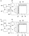
図1〜6を参照して、本発明の一部の実施形態による放射線撮像装置について説明する。図1(a)に、本発明の第1の実施形態における放射線撮像装置200の構成例を示す。放射線撮像装置200は、検出部223、信号処理部224、制御部225、電源回路226を含む。制御部225は、検出部223、信号処理部224及び電源回路226のそれぞれに制御信号を供給し、放射線撮像装置200の各構成要素を制御する。検出部223は、支持基板100、画素アレイ228、駆動回路221、読出回路222を含む。画素アレイ228は支持基板100上に配される。画素アレイ228は、支持基板100の上の撮像領域に配され、放射線画像を取得するための複数の変換素子を含む複数の第1の画素と、入射する放射線量の総量を放射線の照射中に取得するための検出素子を含む第2の画素とを含む。駆動回路221は、画素アレイ228を駆動する。読出回路222は、画素アレイ228の各変換素子及び検出素子に入射した放射線によって生成された信号を電気信号として読み出す。信号処理部224は、読出回路222から読み出された検出素子の電気信号を制御部225に転送する。制御部225は、この検出素子からの電気信号に応じて、検出部223での放射線のサンプリング動作や、放射線源227の放射線の照射を制御するための信号を出力する。また、信号処理部224は、制御部225から供給される制御信号に応じて、読出回路222から読み出された電気信号を放射線撮像装置200の外部に配された画像処理部(不図示)に供給する。電気信号の供給を受けた画像処理部(不図示)は、電気信号から画像を生成しディスプレイ(不図示)などに出力してもよい。これによって、放射線撮像装置200のユーザーは、撮像した放射線画像を観察することができる。また、電気信号の画像化処理は、信号処理部224で行ってもよい。電源回路226は、放射線撮像装置200の各構成要素にバイアス電圧を供給する。本実施形態において、信号処理部224及び制御部225は、それぞれ別の構成になっているが、例えば制御部225が信号処理部224の処理を行う一体の構成になっていてもよい。
First Embodiment A radiation imaging apparatus according to some embodiments of the present invention will be described with reference to FIGS. FIG. 1A shows a configuration example of a
放射線撮像装置200には、放射線を照射する放射線源227と放射線源227を制御する放射線制御部229とが接続される。放射線制御部229は、制御部225から供給される制御信号に応じて放射線源227を制御する。本実施形態において、放射線制御部229によって放射線源227が制御されているが、制御部225が、放射線制御部229を介さずに放射線源227に制御信号を直接、供給してもよい。また例えば、本実施形態において、放射線撮像装置200と放射線制御部229とは、それぞれ別個に配される構成となっているが、放射線撮像装置200が、次に述べる放射線制御部229の機能の少なくとも一部を含んでいてもよい。また、放射線撮像装置200と放射線制御部229とが、一体で構成されていてもよい。
The
放射線撮像の際、撮像条件である管電流や管電圧などの条件は、放射線制御部229に外部から入力されうる。また放射線の照射時間などの条件も、放射線制御部229に外部から入力され、放射線源227の制御に用いられうる。管電流、管電圧、照射時間などの撮像条件は、ユーザーによって放射線制御部229に値を直接入力されてもよい。また、撮像条件は撮像モードごとに予め設定され、例えば放射線制御部229に保存された撮像条件のレシピからユーザーによって選択されてもよい。放射線制御部229は、ユーザーから撮像の条件などの情報の入力を受け付けるユーザーインターフェースを有し、構成の一部に例えばパソコンを用いてもよいし、また、放射線源を含む放射線発生装置に付属の制御卓を含んでいてもよい。
At the time of radiation imaging, conditions such as tube current and tube voltage, which are imaging conditions, can be input to the
次に、図2を用いて検出部223について説明する。検出部223は、上述したように画素アレイ228の配された支持基板100、駆動回路221、読出回路222を含む。画素アレイ228は、行列状に配された複数の画素を含む。複数の画素は、第1の画素101と第2の画素121とを含む。
Next, the
第1の画素101は、放射線画像を取得するために、入射した放射線又は光を入射した量に応じた電荷に変換する変換素子102と、変換素子102で生成された電荷を信号線に出力するスイッチ素子103とを含む。変換素子102は、例えば放射線を光に変換するシンチレータと、シンチレータで変換された光を電荷に変換する光電変換素子とを用いた間接型の変換素子であってもよい。また、変換素子102として、例えば放射線を直接電荷に変換する直接型の変換素子を用いてもよい。スイッチ素子103として、例えば非晶質シリコン又は多結晶シリコンを用いた薄膜トランジスタ(TFT)を用いることができる。例えば、TFTに求められる特性に応じて、多結晶シリコンを用いてもよい。また、TFTに用いる半導体材料は、シリコンに限られるものではなく、ゲルマニウムや化合物半導体などの他の半導体材料を用いてもよい。
The
変換素子102の第1電極には、スイッチ素子103の第1主電極が電気的に接続され、変換素子102の第2電極には、バイアス線108が電気的に接続される。バイアス線108は、列に沿って配された複数の変換素子102の第2電極に共通して接続される。各列に配されたバイアス線108には、共通のバイアス電圧が供給される。バイアス線108は、図1に示す電源回路226よりバイアス電圧の供給を受ける。
The first electrode of the
スイッチ素子103の第2主電極には、信号線106が電気的に接続される。信号線106には、列に沿って配された画素のスイッチ素子103の第2主電極が共通に接続される。信号線106は、画素の列ごとに配される。各信号線106は、読出回路222に電気的に接続される。スイッチ素子103の制御電極には、駆動線104が電気的に接続される。駆動線104は、行に沿って配された複数の第1の画素101のスイッチ素子103の制御電極に共通に接続され、駆動線104には、駆動回路221からゲート制御電圧Vg1〜Vgnが印加される。
The
第2の画素121は、入射する放射線量の総量を放射線の照射中に取得するために、入射した放射線又は光を入射した量に応じた電荷に変換する検出素子122と、検出素子122で生成された電荷を信号線に出力するスイッチ素子123とを含む。また、第2の画素121は、変換素子102とスイッチ素子103とを含んでいてもよい。検出素子122は変換素子102と、スイッチ素子123はスイッチ素子103と、それぞれ同様の構成を有していてよい。
The
検出素子122の第1電極には、スイッチ素子123の第1主電極が電気的に接続され、検出素子122の第2電極には、列ごとに配されたバイアス線108が電気的に接続される。検出線110には、列に沿って配されたスイッチ素子123の第2主電極が接続される。各検出線110は、読出回路222に電気的に接続される。スイッチ素子123の制御電極には、行ごとに配された駆動線124が接続される。各駆動線124には、駆動回路221からゲート制御電圧Vd1〜Vdnが印加される。
A first main electrode of the
第2の画素121は、図2に示すように撮像領域に複数配されていてもよいし、例えば1つだけ配されていてもよい。複数配されている場合、入射する放射線量の検出は、複数配されている第2の画素121の検出素子122のうち1つだけで行われてもよいし、複数の検出素子によって行われてもよい。
A plurality of
読出回路222では、信号線106及び検出線110が、それぞれオペアンプ150の反転入力端子に接続される。またオペアンプ150の反転入力端子は、帰還容量を介し出力端子に接続され、非反転入力端子は、任意の固定電位に接続される。オペアンプ150は、電荷電圧変換回路として機能する。オペアンプ150の後段に、サンプルホールド回路151、マルチプレクサ152を介してADコンバータ153が接続される。読出回路222は、信号線106及び検出線110を介して第1の画素101、第2の画素121それぞれの変換素子102及び検出素子122から転送される電荷をデジタル信号の電気信号に変換するデジタル変換回路を構成する。読出回路222は、各回路を集積化してもよいし、回路ごとに個別に配置してもよい。
In the
次に、図3を用いて本実施形態の第1の画素101及び第2の画素121の構造について説明する。図3(a)は第1の画素101の平面図、図3(b)は第2の画素121の平面図、図3(c)は図3(b)のA−A’間の第2の画素121の断面図をそれぞれ示す。本実施形態において、放射線を光に変換するシンチレータと、シンチレータで変換された光を電荷に変換する光電変換素子とを用いた間接型の変換素子を用いる。図3(a)に示すように第1の画素101には、変換素子102とスイッチ素子103とが配される。また、図3(b)に示すように第2の画素121には、変換素子102及びスイッチ素子103と、検出素子122及びスイッチ素子123とが配される。図3(c)に示すように変換素子102には、PIN型のフォトダイオード134を用いてもよい。また、検出素子122にも、変換素子102と同様にPIN型のフォトダイオード135を用いてもよい。変換素子102は、ガラス基板などの絶縁性の支持基板100の上に設けられたTFTを用いたスイッチ素子103の上に、層間絶縁層130を挟んで積層される。同様に検出素子122は、支持基板100の上に設けられたTFTを用いたスイッチ素子123の上に、層間絶縁層130を挟んで積層される。
Next, the structure of the
変換素子102と検出素子122とは、互いに隣接する変換素子102の第1電極131と検出素子122の第1電極132とが導通しないように絶縁され、第1電極131と第1電極132との間に設置された素子間絶縁膜133が絶縁性を高めている。第1電極131、132及び素子間絶縁膜133上には、それぞれPIN型のフォトダイオード134、135がn層−i層−p層の順で積層される。フォトダイオード134、135上には、それぞれの第2電極136、137が配置される。更にフォトダイオード134、135を覆うように保護膜138、第2層間絶縁層139、バイアス線108、保護膜140が配される。保護膜140上には、平坦化膜(不図示)及びシンチレータ(不図示)が配される。第2電極136、137は、共にバイアス線108に接続される。本実施形態において、第2電極136、137には、例えば酸化インジウムスズ(ITO)などの光透過性を有する電極が用いられる。第2電極136、137は、保護膜140上のシンチレータ(不図示)で放射線から変換された光がフォトダイオード134、135に透過可能な構成となっている。
The
図3(a)及び図3(b)に示すように、第1の画素101と第2の画素121とでは、変換素子102の大きさが異なる。このため、第1の画素101と第2の画素121とに入射する放射線の入射量が同一であった場合においても、それぞれの変換素子102から出力される電荷量が異なる。第2の画素121の変換素子102から出力された電荷から読出回路222で読み出された電気信号を放射線画像に用いる場合は、白補正(ゲイン補正)など、適宜必要な補正を行なうとよい。また、例えば、第2の画素121に変換素子102を配置せず、検出素子122のみを配置してもよい。この場合、放射線画像を形成するための電気信号を出力しない画素が生じるが、第2の画素121の周囲に配された第1の画素101から出力される電気信号を用いて放射線画像を補正してもよい。また、検出素子122において、入射する放射線量の検出に用いた電気信号を放射線画像の形成に用いてもよい。
As shown in FIGS. 3A and 3B, the size of the
次いで、放射線画像撮像における各構成要素の動作フローについて、図4を用いて説明する。図4(a)は、本実施形態における撮像時のフローチャートである。まずユーザーが放射線制御部229のユーザーインターフェース上で、撮像情報の入力を行う。撮像情報には、例えば放射線源の管電圧及び管電流、照射時間、目標放射線量などが含まれる。また、検出素子122が画素アレイ228に複数配されている場合、複数の検出素子122のうち入射する放射線量を取得する検出素子122、換言すると入射する放射線量を取得する位置の情報が含まれていてもよい。また例えば、放射線画像の1つの画素を、複数の第1の画素101や第2の画素121の変換素子102の出力を用いて形成する場合のビニング数や、読出回路222におけるゲインの設定などが含まれていてもよい。また、撮像情報をユーザーが1つ1つ入力するのではなく、例えば、予め設定された撮像情報の組み合わせを、放射線制御部229に保存されたレシピからユーザーが選択してもよい。また、例えばユーザーが撮像部位や被写体の年齢、体格などを入力することで、撮像情報の組み合わせを放射線制御部229が自動的に決定してもよい。放射線制御部229は、撮像情報のうち照射時間、目標放射線量などの放射線の照射情報を、放射線撮像装置200の制御部225に供給する。
Next, an operation flow of each component in radiographic image capturing will be described with reference to FIG. FIG. 4A is a flowchart at the time of imaging in the present embodiment. First, the user inputs imaging information on the user interface of the
本実施形態において、制御部225は、放射線制御部229から入力された放射線の照射情報のうち照射時間の情報に基づき、放射線画像を取得する放射線照射期間中に検出素子122に入射する放射線量の検出する検出周期を決定する。検出周期は、例えば照射時間に対してサンプリング回数が一定となるように決定してもよい。この場合、例えば制御部225に搭載されたFPGAなどの演算素子を用いて、検出周期を演算によって決定してもよい。また例えば、検出周期は、照射時間と検出周期との関係をルックアップテーブル(LUT)として制御部225のメモリ内に格納しておき、放射線制御部229から入力された照射時間に対してLUTの情報から決定してもよい。
In the present embodiment, the
例えば、制御部225は、放射線制御部229から入力された照射時間に対して、サンプリング回数が100回となるように照射時間を分割し、分割された時間を検出周期として用いる。この場合、例えば照射時間が300msであれば検出周期を3msに決定し、また、照射時間が100msであれば検出周期を1msに決定する。
For example, the
また、放射線画像の1つの画素を、放射線撮像装置200に含まれる複数の第1の画素101や第2の画素121に含まれる複数の変換素子102の出力を用いて形成する場合、ビニング数に基づいて検出周期を決定してもよい。例えば、1つの照射時間の情報に対して、ビニング数が多い場合、サンプリング回数を増やし検出周期を短くしてもよいし、ビニング数が少ない場合、サンプリング回数を減らし検出周期を長くしてもよい。
When one pixel of the radiation image is formed using the outputs of the plurality of
検出周期を決定した後、放射線が照射される前に、決定した検出周期に基づいて、制御部225は、決定した検出周期で動作する第2の画素121が出力するノイズのノイズ量を決定する。例えば、制御部225は、決定した検出周期で放射線の照射前に放射線照射時と同じ動作を第2の画素121に行わせ、第2の画素121から出力された電気信号の信号値をノイズ量として用いてもよい。ノイズ量は、決定した検出周期で1度だけ動作させて取得した信号値を用いてもよいし、複数回動作させて取得した信号値を用いてもよい。複数回動作させて信号値を複数取得した場合、例えば各信号値の平均値をノイズ量として用いてもよい。信号値を複数取得し、平均化することによって、第2の画素121から出力されるノイズのうち、ランダムな成分の影響を抑制することが可能となる。ノイズ量は、放射線の照射中に第2の画素121で取得された放射線量を補正するために使用される。
After the detection cycle is determined and before radiation is applied, the
検出周期及びノイズ量を決定した後、ユーザーが放射線制御部229に設けられた曝射スイッチをONにすると、曝射命令が、放射線制御部229から放射線源227及び放射線撮像装置200の制御部225に出力される。放射線源227は、曝射命令に従って放射線の照射を開始する。また、制御部225は、曝射命令に従って検出部223を動作させ、放射線画像の取得を開始する。具体的には、検出部223の画素アレイ228に配された第1の画素101の変換素子102のそれぞれに入射した放射線量に応じた電荷を蓄積させる。また同時に、第2の画素121の検出素子122に入射する放射線量を先に決定した検出周期で取得する検出動作を開始させる。ここで、曝射スイッチが、放射線源227の放射線管球のアイドリングを開始させるスイッチと、放射線の被写体への照射を行うスイッチの2段スイッチになっていてもよい。この場合、放射線管球のアイドリングを開始させるスイッチがONした段階で、制御部225は、放射線の照射情報から先に決定した検出周期で検出素子を動作させ、ノイズ量を決定してもよい。検出周期に基づいてノイズ量を決定した後、放射線の被写体への照射を行い、放射線画像の取得を開始する。
After the detection cycle and the noise amount are determined, when the user turns on the exposure switch provided in the
次に制御部225は、第2の画素121の検出素子122によって検出周期ごとに取得された放射線量を放射線の照射前に決定したノイズ量に従って補正し、補正後の放射線量の累計値を取得する。次いで取得した放射線量の累計値を放射線制御部229から供給された照射情報のうち目標放射線量の情報と比較する。制御部225は、補正後の放射線量の累計値を目標放射線量と比較した結果に基づいて、放射線の照射を継続させるか又は停止させるかを判定する曝射停止判定を行う。第2の画素121の検出素子122で検出された放射線量の累計値が、目標放射線量に達していない場合、制御部225は、放射線の照射の継続が必要と判定し、放射線画像の取得及び検出動作を継続する。第2の画素121の検出素子122で検出された放射線量の累計値が、照射される放射線の目標放射線量に達した場合、又は、前記目標放射線量に達すると予想した場合、放射線の照射を停止させるための停止判定信号を放射線制御部229に出力する。放射線制御部229は、制御部225から出力される停止判定信号に基づいて曝射停止命令を放射線源227に対して出力する。曝射停止命令に従い、放射線源227は放射線の照射を停止する。放射線の照射の停止は、曝射停止命令を出力するのではなく、例えば放射線制御部229から放射線源227に出力していた曝射命令を停止することによって、照射を停止してもよい。また曝射停止命令の出力に応じて、検出部223は、検出動作を停止してもよい。
Next, the
本実施形態において、曝射停止判定は、放射線撮像装置200の制御部225で行うが、これに限られるものではない。例えば、図4(b)に示すように、制御部225が、第2の画素121の検出素子122で検出された放射線量をノイズ量に従って補正した放射線量の累計値を放射線制御部229に出力する。この補正した放射線量の累計値に基づいて放射線制御部229が、停止判定を行い曝射停止命令を出力してもよい。この場合、放射線の照射前に、放射線制御部229は、撮像情報のうち照射時間の情報を照射情報として制御部225に供給し、目標放射線量の情報を制御部225に送らなくてもよい。また、放射線画像の取得及び放射線量の検出動作は、放射線制御部229が曝射停止判定を行い曝射停止命令を出力したことに応じて停止してもよい。
In the present embodiment, the emission stop determination is performed by the
また、制御部225は、放射線源227による放射線の被写体に対する照射時間が、放射線の照射前に放射線制御部229から供給された照射時間の情報のうち照射時間の上限に到達した場合、曝射停止信号を出力してもよい。曝射停止信号に従って放射線制御部229は、曝射停止命令を放射線源227に出力し、放射線源227は、放射線の照射を停止する。検出素子122に入射した放射線量の累計値が、目標放射線量に達する前、又は、目標放射線量に達すると予想する前であっても照射時間の上限に従って放射線の照射を停止する。これによって、例えば、第2の画素121の検出素子122に入射する放射線量の検出が正常にできていない場合であっても、被写体への過剰な放射線照射を避けることができる。
The
次いで、本実施形態において、放射線画像撮像における各構成要素の動作タイミングについて、図2、4、5を用いて説明する。図5は、放射線撮像装置200の各構成要素の動作タイミングを示すタイミングチャートである。図4、5に示す期間T1は、待機中のアイドリング期間を表す。この期間T1において、図5に示すように駆動回路221から印加される信号によって画素アレイ228は、アイドリング動作を繰り返す。アイドリング動作は、例えば検出部223の電源投入後、撮像が開始されるまで行われてもよい。図4において、期間T1は、ユーザーが撮像情報の入力をしている時間や、ユーザーが曝射スイッチを押すまでの時間、放射線撮像装置200の制御部225が検出周期を決定する時間である。
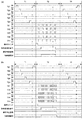
Next, in the present embodiment, the operation timing of each component in radiographic imaging will be described with reference to FIGS. FIG. 5 is a timing chart showing the operation timing of each component of the
期間T1の間、変換素子102から発生するダーク電流を定期的に除去するために、ゲート制御電圧Vg1〜Vgnに定期的にHi信号が印加され、第1の画素101のスイッチ素子103が走査される。同様に、第2の画素121の検出素子122から発生するダーク電流を除去するために、ゲート制御電圧Vd1〜Vdnには常にHi信号が印加され、第2の画素121のスイッチ素子123が導通した状態となる。ここでHi信号は、各スイッチ素子103、123がONとなる電圧であり、Lo信号は、各スイッチ素子103、123がOFFとなる電圧(例えば、0V)である。また、図5に示す本実施形態のタイミングチャートにおいて、検出素子122を複数用いて入射する放射線量を検出する例が示されている。この場合、それぞれの検出素子122には、同じ目標放射線量が設定されていてもよいし、それぞれ異なる目標放射線量が設定されていてもよい。また、制御部225は、複数の第2の画素121の検出素子122のうち1つが目標放射線量に達したときに停止判定信号を出力してもよいし、すべての検出素子122が目標放射線量に達したときに停止判定信号を出力してもよい。これらの設定は、被写体や撮像条件、検出素子122の画素アレイ228内での位置などによって、適宜設定すればよい。
During the period T1, a Hi signal is periodically applied to the gate control voltages Vg1 to Vgn to periodically remove a dark current generated from the
次に、曝射スイッチ、又は、放射線源227の放射線管球のアイドリングを開始させるスイッチが押されると期間T2に移行する。期間T2は、第2の画素121のノイズのノイズ量を決定し、その後、放射線を照射し放射線画像を取得する期間である。図5は、曝射スイッチをONすることで、撮像が開始される場合のタイミングチャートを示す。期間T2において、スイッチ素子103を駆動するゲート制御電圧Vg1〜VgnにLo信号が印加され、変換素子102のそれぞれは、入射した放射線量に応じた電荷を蓄積する。また、スイッチ素子123を駆動するゲート制御電圧Vd1〜VdnにHi信号が期間T1で決定された検出周期で印加され、検出素子122で検出された電荷が、検出線110を介して読出回路222に送られる。読出回路222は、検出された電荷に基づいた電気信号を、信号処理部224を介して制御部225に供給し、制御部225は検出素子122に入射する放射線量を検出周期ごとに取得する。
Next, when the exposure switch or the switch for starting the idling of the radiation tube of the
まず、曝射スイッチが押され、放射線の照射される前に読出回路222に読み出された電気信号によって、制御部225は、第2の画素121のノイズ量を取得する。図5(a)と図5(b)は、事前に放射線制御部229から制御部225に転送された照射情報のうち照射時間の異なる場合のタイミングチャートを示している。図5(b)は、図5(a)よりも短い照射時間が入力されており、そのためゲート制御電圧Vd1〜VdnがHi信号となる周期も短くなっている。図5(a)に示すタイミングチャートの場合、放射線の照射前に第2の画素121から1回、出力された信号値をノイズ量として用いる。また、図5(b)に示すタイミングチャートの場合、検出周期が短いため、放射線の照射前に第2の画素121から出力された信号値の2回分の信号値を平均化してノイズ量として用いる。複数取得した信号値を平均化することによって、検出周期が短く信号量が少ない場合でも、ランダムノイズの影響を抑制したノイズを取得することができる。これによって、放射線照射中に入射する放射線量の累計値を求める際に、より正確に補正を行うことが可能となる。検出素子122のノイズ量を決定した後、放射線が照射され、変換素子102のそれぞれは、入射した放射線量に応じた電荷を蓄積し、放射線画像が撮像される。
First, the
また、図5では、スイッチ素子123の制御電極に印加されるゲート制御電圧Vd1〜Vdnが、同時にHi信号となるが、期間T2における動作は、これに限られるものではない。例えば図6に示すように、同じ検出線110に接続された検出素子122用のスイッチ素子123に対応するゲート制御電圧Vd1〜VdnのHi信号のタイミングを分けても良い。この場合、一度に読み出し可能な信号量が減るものの検出領域の空間解像度を上げることが可能となる。
In FIG. 5, the gate control voltages Vd1 to Vdn applied to the control electrode of the
検出素子122から読出回路222に送られた電荷は、オペアンプ150で電圧情報に変換される。次いで、サンプルホールド回路151によって検出周期に基づきサンプリングされ、マルチプレクサ152を介してADコンバータ153でデジタルデータの電気信号に変換される。
The charge sent from the
制御部225は、検出素子122で検出し電荷から電気信号に変換された放射線量をノイズ量に従って補正する。その後、補正した放射線量の累計値と、事前に放射線制御部229から制御部225に転送された目標放射線量の情報とに基づいて、放射線の曝射停止判定を行う。制御部225は、照射された放射線の累計値が目標放射線量に達した場合、又は、前記目標放射線量に達すると予想した場合、放射線の照射を停止させる停止判定信号を放射線制御部229に出力し、放射線制御部229は放射線源227に放射線の照射を停止させる。また、期間T2は、撮像モードや事前に入力された照射時間ごとに、期間の長さが予め決められていてよい。例えば、上述のように目標放射線量に達しない場合でも、照射情報として入力された照射時間の上限になった場合、放射線の照射を停止させる。検出素子122で検出された放射線量の累計値が目標放射線量に達した後、又は、所定の時間が経過した後、期間T2から期間T3に移行する。
The
期間T3は、放射線の照射後に、撮像した放射線画像を取得する期間である。期間T3の間、制御部225は、変換素子102に蓄積された信号電荷を読み出すための制御信号を駆動回路221に出力する。駆動回路221は、制御信号に応じてゲート制御電圧Vg1〜Vgnに順次Hi信号を印加し、第1の画素101及び第2の画素121のスイッチ素子103を順次走査する。変換素子102に蓄積された電荷は、オペアンプ150で電圧情報に変換され、サンプルホールド回路151によってサンプリングされ、マルチプレクサ152を介してADコンバータ153でデジタルデータの電気信号に変換される。変換素子102によって取得され、読み出された電気信号に基づいて、放射線画像が形成される。
The period T3 is a period in which a captured radiation image is acquired after irradiation with radiation. During the period T3, the
ここで、本実施形態の効果について説明する。図5に示す期間T2において、事前に入力された照射時間に基づき、適切な検出周期で第2の画素121から検出信号がサンプリングされる。このため、放射線の照射時間が長く、単位時間あたりの放射線の入射量が少ないエネルギーの弱い放射線の入射の場合、検出周期を長く設定することによって信号の蓄積時間が長くなり、検出信号がノイズに埋もれる可能性が抑制される。また、放射線の照射時間が短く、単位時間あたりの放射線の入射量が多いエネルギーの強い放射線の入射の場合、検出周期を短く設定することによって検出素子122の電荷を蓄積する容量を飽和させることなく、検出信号を取得することができる。
Here, effects of the present embodiment will be described. In a period T2 shown in FIG. 5, a detection signal is sampled from the
また、第2の画素121が出力するノイズのノイズ量は、検出素子122やスイッチ素子123の動作条件によって変化しうる。例えば、検出周期や撮像時の温度などによって、検出素子122の暗電流やスイッチ素子123のオフセットレベルが変化する可能性がある。これらの影響によって第2の画素121から出力されるノイズのノイズ量が変化しうる。そこで、本実施形態において、放射線の照射前に、放射線を検出する際と同じ検出周期で第2の画素が出力するノイズのノイズ量を取得する。このため、第2の画素121の検出周期や撮像環境に合わせたノイズ量を取得することができる。
Further, the noise amount of the noise output from the
ユーザーによって事前に入力された撮像情報のうち放射線の照射情報に基づき、適切な検出周期で第2の画素121を動作させる。また、同じ検出周期で第2の画素121のノイズ量を事前に取得する。その後、放射線を照射し、放射線照射中に第2の画素121で取得した放射線量をノイズ量に従って補正することによって、実際に放射線撮像装置200に入射した放射線量をより高い精度で取得することが可能となる。これによって、撮像する際の露光量をより適切な量とすることができ、撮像画像の画質が向上しうる。
The
第2の実施形態
図7(a)を参照して、本発明の第2の実施形態による放射線撮像装置について説明する。図7(a)は、本実施形態における放射線画像撮像における各構成要素の動作フローについて説明する撮像時のフローチャートである。放射線撮像装置200、放射線制御部229及び放射線源227の構成は、上述した第1の実施形態の図1に示す構成と同じであってよい。第1の実施形態において、放射線量を検出するための検出周期は、撮像情報のうち、放射線の照射情報として照射時間の情報を用いて決定した。一方、本実施形態では、照射情報として放射線源の管電圧及び管電流、放射線源と被写体との距離、グリット露出倍数、被写体厚、被写体関心領域の放射線透過率、Alなどの付加フィルターの放射線吸収率を含む情報のうち少なくとも1つの情報を利用する。これらの情報を用い照射される放射線の照射量に関わる単位時間当たりの入射する放射線の推定放射線量、又は、入射する放射線量に相関のある物理量を推定することによって、適切な検出周期を決定する。
Second Embodiment A radiation imaging apparatus according to a second embodiment of the present invention will be described with reference to FIG. FIG. 7A is a flowchart at the time of imaging for explaining the operation flow of each component in radiographic image imaging in the present embodiment. The configurations of the
放射線源の管電圧及び管電流、放射線源と被写体との距離、グリット露出倍数、被写体厚、被写体関心領域の放射線透過率、付加フィルターの放射線吸収率などの撮像情報は、放射線制御部229のユーザーインターフェースから入力してもよい。また、放射線撮像装置200、放射線制御部229及び放射線源227の各部にセンサーを設け、自動で撮像情報の何れかを取得してもよい。例えば、放射線源227に取り付けた赤外線センサーによって、放射線源227と被写体との間の距離を測ってもよい。また例えば、放射線制御部229に接続されたカメラによって、被写体厚を推定してもよいし、関心領域となる被写体の部位を特定し、被写体関心領域の放射線透過率を推定してもよい。また例えば、事前のキャリブレーションによって、放射線源と被写体との距離、グリット露出倍数、付加フィルターの放射線吸収率などを取得しておいてもよい。また例えば、放射線撮像装置200がユーザーインターフェースを有し、そこに撮像情報を入力してもよい。
The imaging information such as the tube voltage and tube current of the radiation source, the distance between the radiation source and the subject, the multiple grit exposure, the subject thickness, the radiation transmittance of the subject region of interest, the radiation absorption of the additional filter, and the like, It may be input from the interface. In addition, a sensor may be provided in each unit of the
本実施形態において、放射線制御部229から放射線撮像装置200に撮像情報のうち、放射線撮像装置200に照射される放射線の照射量に関わる照射情報を送る。この照射情報に対して以下に示す式(1)を用いて、単位時間あたりに入射する放射線の推定放射線量を、放射線撮像装置200の制御部225が演算することによって求める。
In the present embodiment, the

ここで、V:管電圧、n:管電圧指数、I:管電流、SID:被写体距離、B:グリット露出倍数、d:被写体厚、μ:被写体関心領域の放射線透過率、Al(V):付加フィルターの放射線吸収率、E(t):単位時間あたりに入射する放射線の推定放射線量である。単位時間あたりに入射する放射線量の推定値E(t)は、単位時間あたりの検出信号の量と比例するため、検出周期は、この値に比例するように決定される。 Here, V: tube voltage, n: tube voltage index, I: tube current, SID: subject distance, B: grid exposure multiple, d: subject thickness, μ: radiation transmittance of the region of interest of the subject, Al (V): Radiation absorptivity of the additional filter, E (t): Estimated radiation dose of radiation incident per unit time. Since the estimated value E (t) of the radiation amount incident per unit time is proportional to the amount of the detection signal per unit time, the detection cycle is determined to be proportional to this value.
また、式(1)に示すすべて照射情報が得られない場合、情報が得られなかったパラメータに関しては、例えば標準的な値を入力すればよい。少なくとも1つの照射情報を入力することによって、検出周期が最適値に近付き、入射する放射線量をより精度よく取得することが可能となる。 When all the irradiation information shown in the equation (1) cannot be obtained, for example, a standard value may be input for a parameter for which information was not obtained. By inputting at least one irradiation information, the detection cycle approaches the optimum value, and it becomes possible to acquire the incident radiation dose with higher accuracy.
検出素子122が出力するノイズのノイズ量は、上述の第1の実施形態と同様に、期間T2において、放射線の照射前に第2の画素121を動作させ取得してもよい。また、事前に放射線の照射をせずに第2の画素121を複数の検出周期で動作させ、このとき第2の画素121から出力された各信号値を、例えば図1(a)に示すように制御部225にノイズ量記録部231を設け記録しておく。この各信号値を用いて、決定された検出周期に応じて例えば制御部225が演算を行い、ノイズ量を決定してもよい。例えば、第2の画素121において、事前に検出周期Aで取得したノイズ量aと、検出周期Bで取得したノイズ量bとを取得しておく。ここで検出周期が検出周期Cと決定した場合、補正に用いるノイズ量cは、次に示す式(2)を用いて算出してもよい。
The noise amount of the noise output from the
複数の検出周期での各信号値の取得は、例えば、放射線撮像装置200の電源投入時や、期間T1の間に行ってもよい。また例えば、工場出荷時に複数の検出周期での信号値の取得を行い、各信号値をノイズ量記録部231に保存しておいてもよい。
The acquisition of each signal value in a plurality of detection cycles may be performed, for example, when the
また例えば、検出周期とノイズ量との関係をLUTとしてノイズ量記録部231に格納しておき、決定した検出周期に対して制御部225がLUTの情報からノイズ量を決定してもよい。ノイズ量の決定を上述の演算やLUTの情報を用いて行う場合、ノイズ量の決定は、図7(a)に示すように期間T1の間に行ってもよい。
Alternatively, for example, the relationship between the detection cycle and the noise amount may be stored in the noise
本実施形態において、検出周期を決定するために、放射線源の管電圧、管電流など、放射線の入射量に関わる情報を用いることによって、単位時間あたりに放射線撮像装置200に入射する放射線量を推定する。したがって、単位時間あたりの入射する放射線量が少ない場合、検出周期が長く設定され、信号の蓄積時間が長くなるため、検出信号がノイズに埋もれる可能性が抑制される。一方、単位時間あたりの入射する放射線量が多い場合、検出周期が短く設定され、検出素子122の電荷を蓄積できる容量に対して適切な信号量の検出信号取得することができる。また、決定した検出周期に応じて、検出素子122の出力するノイズのノイズ量を決定する。これによって、上述の第1の実施形態と同様に、放射線撮像装置200に入射した放射線量をより高い精度で取得することが可能となり、撮像画像の画質が向上しうる。
In the present embodiment, in order to determine the detection cycle, the amount of radiation incident on the
第3の実施形態
図1(b)及び図7(b)を参照して、本発明の第3の実施形態による放射線撮像装置について説明する。図1(b)は、本実施形態における放射線撮像装置200aの構成例を示す。図1(a)に示す第1の実施形態と比較して、放射線撮像装置200aに接続された放射線源227を制御する放射線制御部229がデータベース230と接続される。これ以外の点は、上述した図1(a)に示す放射線撮像装置200と同様であってよい。
Third Embodiment A radiation imaging apparatus according to a third embodiment of the present invention will be described with reference to FIGS. 1B and 7B. FIG. 1B illustrates a configuration example of the radiation imaging apparatus 200a according to the present embodiment. Compared to the first embodiment shown in FIG. 1A, a
データベース230には、照射時間の情報を含む過去の撮像条件に関わる撮像情報が保存されている。第1の実施形態において、放射線量を検出するための検出周期は、撮像情報のうち照射時間の情報を用いて決定した。一方、本実施形態において検出周期は、図7(b)のフローチャートに示すように、まず、ユーザーが放射線制御部229のユーザーインターフェースに入力した撮像情報を、放射線制御部229がデータベース230に保存された情報と比較する。例えば、ユーザーが放射線制御部229に、例えば放射線の管電圧及び管電流、撮像部位、被写体厚などに関わる撮像情報を入力する。放射線制御部229は、入力された撮像情報に類似する撮像情報を有する過去の撮像条件をデータベース230から検索し、検索された撮像時に実際に放射線を照射した照射時間の実績値を調査する。次いで放射線制御部229は、照射時間の実績値を制御部225に転送し、この実績に基づいて制御部225は、検出周期を決定する。また、データベース230に検出周期が記録されていてもよい。次いで、決定した検出周期に基づいて、制御部225は第2の画素121の出力するノイズのノイズ量を決定する。ノイズ量の決定は、上述の第1及び第2の実施形態の方法の何れかを用いてもよい。
The database 230 stores imaging information relating to past imaging conditions including irradiation time information. In the first embodiment, the detection cycle for detecting the radiation dose is determined using the irradiation time information in the imaging information. On the other hand, in the present embodiment, as shown in the flowchart of FIG. 7B, the
本実施形態では、ユーザーによって入力された撮像情報に対して、放射線制御部229がデータベース230の撮像条件を検索するが、これに限られるものではない。例えば、放射線制御部229は、ユーザーによって入力された撮像条件のうち、放射線の照射情報を制御部225に転送し、制御部225が、データベース230の撮像条件を検索してもよい。
In the present embodiment, the
また、データベース230を用いた検出周期の決定方法は、上述の方法に限られるものではない。例えば、経過観察などで同一患者、同一部位の撮像を行う場合、放射線制御部229に患者名や患者識別IDなどを入力することによって、放射線制御部229は、データベース230より過去の撮像時の放射線の照射条件や照射時間などの撮像情報を取得する。この撮像情報に基づき、放射線制御部229から放射線撮像装置200の制御部225に、放射線撮像装置200に照射される放射線の照射時間や照射量に関わる照射情報を転送する。制御部225は、この照射情報に基づいて検出周期を決定してもよい。
Further, the method for determining the detection cycle using the database 230 is not limited to the above-described method. For example, when imaging the same patient and the same site in follow-up observation or the like, by inputting a patient name, a patient identification ID, and the like to the
データベース230に保存される過去の撮像条件に関わる撮像情報は、実際に撮像を行った被写体の撮像ごとに蓄積してもよい。また例えば、データベース230の工場出荷時やメンテナンス時に人為的に作成した撮像情報を保存してもよい。 The imaging information related to the past imaging conditions stored in the database 230 may be accumulated for each image of the subject that actually took the image. Further, for example, imaging information artificially created at the time of factory shipment or maintenance of the database 230 may be stored.
本実施形態では、検出周期を決定するために、例えば放射線の照射時間などの過去の撮像情報を利用する。これによって、放射線の入射量をより精度よく取得することが可能となる。被写体が類似する撮像において、検出周期が一定になるため、類似する撮像条件において、同条件で自動露出制御(AEC)の管理が可能となる。また、決定した検出周期に応じて、検出素子122の出力するノイズのノイズ量を決定する。これによって、上述の第1及び第2の実施形態と同様に、放射線撮像装置200に入射した放射線量をより高い精度で取得することが可能となり、撮像画像の画質が向上しうる。
In the present embodiment, past imaging information such as radiation irradiation time is used to determine the detection cycle. This makes it possible to acquire the amount of incident radiation with higher accuracy. Since the detection cycle is constant in imaging with similar subjects, automatic exposure control (AEC) can be managed under similar imaging conditions under the same conditions. Further, the amount of noise output from the
以上、本発明に係る実施形態を3形態示したが、上述した各実施形態は、適宜変更、組み合わせが可能である。 As described above, three embodiments according to the present invention have been described. However, the embodiments described above can be appropriately changed and combined.
また、制御部225が、放射線の照射情報に対して、検出周期とノイズ量との少なくとも一方を決定できない場合、放射線撮像装置200は、放射線の照射を行わなくてもよい。例えば、入力された撮像条件が、被写体の撮像部位、性別、年齢などによって決まるおおよその推奨値から大きく離れている場合、制御部225は、インターロックなどの機構によって検出周期やノイズ量の決定をできなくてもよい。検出周期やノイズ量の決定をできない場合、例えば制御部225は、放射線制御部229や放射線源227に放射線の照射の開始を許可しなくてもよい。また例えば、照射時間の実績値がデータベース230に保存されていない場合や、放射線の照射時間が短く検出周期の決定ができない場合も、制御部225は放射線の照射の開始を許可しなくてもよい。
When the
以下、図8を参照しながら本発明の放射線撮像装置200が組み込まれた放射線撮像システムを例示的に説明する。放射線源であるX線チューブ6050で発生したX線6060は、患者又は被験者6061の胸部6062を透過し、本発明の放射線撮像装置200に入射する。この入射したX線に患者又は被験者6061の体内部の情報が含まれる。放射線撮像装置200において、X線6060の入射に対応してシンチレータが発光し、これが光電変換素子で光電変換され、電気的情報を得る。この情報は、デジタルに変換され信号処理部としてのイメージプロセッサ6070によって画像処理され、制御室の表示部としてのディスプレイ6080で観察できる。また、この情報は、電話回線6090などの伝送処理部によって遠隔地へ転送できる。これによって別の場所のドクタールームなどの表示部であるディスプレイ6081に表示し、遠隔地の医師が診断することも可能である。また、この情報は、光ディスクなどの記録媒体に記録することができ、またフィルムプロセッサ6100によって記録媒体となるフィルム6110に記録することもできる。
Hereinafter, a radiation imaging system incorporating the
また、本発明は、以下の処理を実行することによっても実現される。即ち、上述した実施形態の機能を実現するソフトウェア(プログラム)を、ネットワーク又は各種記憶媒体を介してシステム或いは装置に供給し、そのシステム或いは装置のコンピュータ(またはCPUやMPU等)がプログラムを読み出して実行する処理である。 The present invention is also realized by executing the following processing. That is, software (program) that realizes the functions of the above-described embodiments is supplied to a system or an apparatus via a network or various storage media, and a computer (or a CPU or an MPU or the like) of the system or the apparatus reads out the program. This is the process to be performed.
101:第1の画素、121:第2の画素、200:放射線撮像装置、225:制御部 101: first pixel, 121: second pixel, 200: radiation imaging apparatus, 225: control unit
Claims (21)
入射する放射線量を放射線の照射中に取得するための第2の画素と、
前記複数の第1の画素及び前記第2の画素を制御する制御部と、を含み、
前記制御部は、
前記複数の第1の画素に放射線量に応じた電荷を蓄積させるとともに、
放射線の照射情報に含まれる、放射線の照射時間の情報、及び、放射線の照射量に関わる情報のうち少なくとも一方に基づいて放射線の照射前に決定した放射線の検出周期で前記第2の画素を動作させながら、入射した放射線量を前記検出周期ごとに取得し、
前記検出周期で動作する前記第2の画素が出力するノイズの、放射線の照射の前に前記検出周期に応じて決定したノイズ量に従って、取得した放射線量を補正する
ことを特徴とする放射線撮像装置。 A plurality of first pixels arranged in an imaging region to acquire a radiation image;
A second pixel for acquiring an incident radiation dose during irradiation of radiation;
A control unit that controls the plurality of first pixels and the second pixels,
The control unit includes:
While accumulating charges corresponding to the radiation dose in the plurality of first pixels,
Included in the irradiation information radiological, information of the irradiation time of the radiation, and, the second pixel in the detection period of the radiation determined before irradiation based on at least one of information related to the dose of radiation While operating, acquire the incident radiation dose for each detection cycle,
A radiation imaging apparatus that corrects an acquired radiation dose according to a noise amount of the noise output by the second pixel that operates in the detection cycle and that is determined according to the detection cycle before radiation irradiation. .
入射する放射線量を放射線の照射中に取得するための第2の画素と、 A second pixel for acquiring an incident radiation dose during irradiation of radiation;
前記複数の第1の画素及び前記第2の画素を制御する制御部と、を含み、 A control unit that controls the plurality of first pixels and the second pixels,
前記制御部は、 The control unit includes:
前記複数の第1の画素に放射線量に応じた電荷を蓄積させるとともに、 While accumulating charges corresponding to the radiation dose in the plurality of first pixels,
放射線の照射前に放射線の照射情報に基づいて決定した放射線の検出周期で前記第2の画素を動作させながら、入射した放射線量を前記検出周期ごとに取得し、 While operating the second pixel in the radiation detection cycle determined based on the radiation irradiation information before the radiation irradiation, to acquire the amount of incident radiation for each detection cycle,
前記検出周期で動作する前記第2の画素が出力するノイズのノイズ量に従って、取得した放射線量を補正し、 According to the noise amount of the noise output by the second pixel operating in the detection cycle, the acquired radiation dose is corrected,
前記照射情報が、前記複数の第1の画素のうち、前記放射線画像の1つの画素を形成するための第1の画素の数の情報を含み、 The irradiation information includes information on the number of first pixels for forming one pixel of the radiation image among the plurality of first pixels,
前記制御部が、前記第1の画素の数に基づいて前記検出周期を決定することを特徴とする放射線撮像装置。 The radiation imaging apparatus, wherein the control unit determines the detection cycle based on the number of the first pixels.
入射する放射線量を放射線の照射中に取得するための第2の画素と、 A second pixel for acquiring an incident radiation dose during irradiation of radiation;
前記複数の第1の画素及び前記第2の画素を制御する制御部と、を含み、 A control unit that controls the plurality of first pixels and the second pixels,
前記制御部は、 The control unit includes:
前記複数の第1の画素に放射線量に応じた電荷を蓄積させるとともに、 While accumulating charges corresponding to the radiation dose in the plurality of first pixels,
放射線の照射前に放射線の照射情報に基づいて決定した放射線の検出周期で前記第2の画素を動作させながら、入射した放射線量を前記検出周期ごとに取得し、 While operating the second pixel in the radiation detection cycle determined based on the radiation irradiation information before the radiation irradiation, to acquire the amount of incident radiation for each detection cycle,
前記検出周期で動作する前記第2の画素が出力するノイズのノイズ量に従って、取得した放射線量を補正し、 According to the noise amount of the noise output by the second pixel operating in the detection cycle, the acquired radiation dose is corrected,
前記制御部が、前記検出周期と前記ノイズ量との少なくとも一方を決定できない場合、放射線の照射を行わないことを特徴とする放射線撮像装置。 If the control unit cannot determine at least one of the detection cycle and the noise amount, the control unit does not irradiate the radiation.
補正後の放射線量に基づいて放射線の照射を停止させ、
放射線の照射後に、前記複数の第1の画素に蓄積された電荷を読み出す
ことを特徴とする請求項1乃至3の何れか1項に記載の放射線撮像装置。 The control unit includes:
Stop irradiation of radiation based on the corrected radiation dose,
The radiation imaging apparatus according to any one of claims 1 to 3 , wherein the charge accumulated in the plurality of first pixels is read after the irradiation of the radiation.
前記照射情報のうち放射線の照射量に関わる情報が、放射線源の管電圧及び管電流、放射線源と被写体との距離の情報、グリット露出倍数の情報、被写体厚の情報、被写体関心領域の放射線透過率の情報、付加フィルターの放射線吸収率の情報のうち少なくとも1つの情報を含み、
前記制御部が、前記照射情報のうち放射線の照射量に関わる情報に従って所定の期間に前記検出素子に入射する放射線の推定放射線量を決定し、前記推定放射線量に基づいて前記検出周期を決定することを特徴とする請求項1乃至4の何れか1項に記載の放射線撮像装置。 The second pixel includes a detection element for acquiring an incident radiation dose during irradiation of the radiation,
Among the irradiation information , information related to the dose of radiation includes a tube voltage and a tube current of a radiation source, information on a distance between the radiation source and a subject, information on a multiple exposure factor, information on a subject thickness, information on a subject's region of interest and radiation transmission. Information on the rate, including at least one of information on the radiation absorption rate of the additional filter ,
The control unit determines an estimated radiation dose of radiation incident on the detection element for a predetermined period according to information on the radiation dose of the radiation information, and determines the detection cycle based on the estimated radiation dose. The radiation imaging apparatus according to claim 1, wherein:
前記制御部が、前記照射情報と前記撮像条件とを比較し、前記照射情報を含む前記撮像条件に基づいて前記検出周期を決定することを特徴とする請求項1乃至4の何れか1項に記載の放射線撮像装置。 The radiation imaging apparatus further includes a recording unit that records imaging conditions,
Wherein the control unit, comparing the image capturing conditions as the irradiation information, to any one of claims 1 to 4, characterized in that determining the detection period based on the imaging condition including the illumination information A radiation imaging apparatus according to claim 1.
前記制御部が、前記検出周期に応じて、前記各信号値を用いて前記ノイズ量を決定することを特徴とする請求項1乃至9の何れか1項に記載の放射線撮像装置。 The radiation imaging apparatus includes a noise amount recording unit in which each signal value output from the second pixel is recorded when the second pixel is operated in a plurality of detection cycles without irradiation of radiation. In addition,
Wherein the control unit is pre-SL in response to the detection period, the radiation imaging apparatus according to any one of claims 1 to 9, wherein determining the noise amount using the signal values.
前記制御部は、補正後の放射線量の累計値が前記目標放射線量に達した場合、又は、前記目標放射線量に達すると予想した場合、前記放射線撮像装置に放射線を照射する放射線源に、放射線の照射を停止させるための停止判定信号を出力することを特徴とする請求項1乃至12の何れか1項に記載の放射線撮像装置。 The irradiation information includes a target radiation dose of radiation incident on the second pixel,
When the cumulative value of the corrected radiation dose reaches the target radiation dose, or when the control unit predicts that the corrected radiation dose will reach the target radiation dose, the radiation source that irradiates the radiation to the radiation imaging apparatus includes radiation. The radiation imaging apparatus according to claim 1, wherein the radiation imaging apparatus outputs a stop determination signal for stopping irradiation of the image.
前記制御部は、前記累計値が前記目標放射線量に達する前、又は、前記目標放射線量に達すると予想する前に放射線の照射時間が前記上限に達した場合、前記放射線源に、放射線の照射を停止させるための停止判定信号を出力することを特徴とする請求項13に記載の放射線撮像装置。 The irradiation information includes an upper limit of the irradiation time of the radiation,
The control unit is configured to irradiate the radiation source before the cumulative value reaches the target radiation dose, or when the irradiation time of the radiation reaches the upper limit before it is expected to reach the target radiation dose. The radiation imaging apparatus according to claim 13, wherein a stop determination signal for stopping the operation is output.
前記第2の画素が前記撮像領域に配されていることを特徴とする請求項1乃至15の何れか1項に記載の放射線撮像装置。 The plurality of first pixels include a plurality of conversion elements arranged in an imaging region to acquire a radiation image,
The radiation imaging apparatus according to any one of claims 1 to 15, wherein the second pixel is arranged in the imaging region.
前記放射線撮像装置からの信号を処理する信号処理部と、を備えることを特徴とする放射線撮像システム。 A radiation imaging apparatus according to claim 1,
A signal processing unit that processes a signal from the radiation imaging apparatus.
入射する放射線の線量を放射線の照射中に取得するための第2の画素と、を含む放射線撮像装置の制御方法であって、
前記複数の第1の画素に放射線量に応じた電荷を蓄積させる工程と、
放射線の照射情報に含まれる、放射線の照射時間の情報、及び、放射線の照射量に関わる情報のうち少なくとも一方に基づいて放射線の照射前に決定した放射線の検出周期で前記第2の画素を動作させながら、入射した放射線量を前記検出周期ごとに取得する工程と、
前記検出周期で動作する前記第2の画素が出力するノイズの、放射線の照射の前に前記検出周期に応じて決定したノイズ量に従って、取得した放射線量を補正する工程と、
を含むことを特徴とする制御方法。 A plurality of first pixels arranged in an imaging region to acquire a radiation image;
A second pixel for acquiring a dose of incident radiation during irradiation of radiation, and a control method of a radiation imaging apparatus including:
Accumulating charges corresponding to the radiation dose in the plurality of first pixels;
Included in the irradiation information radiological, information of the irradiation time of the radiation, and, the second pixel in the detection period of the radiation determined before irradiation based on at least one of information related to the dose of radiation While operating, acquiring the incident radiation dose for each of the detection cycles,
Correcting the acquired radiation dose according to the noise amount determined according to the detection period before the irradiation of the radiation, of the noise output by the second pixel operating in the detection period ,
A control method comprising:
入射する放射線の線量を放射線の照射中に取得するための第2の画素と、を含む放射線撮像装置の制御方法であって、 A second pixel for acquiring a dose of incident radiation during irradiation of radiation, and a control method of a radiation imaging apparatus including:
前記複数の第1の画素に放射線量に応じた電荷を蓄積させる工程と、 Accumulating charges corresponding to the radiation dose in the plurality of first pixels;
放射線の照射前に放射線の照射情報に基づいて決定した放射線の検出周期で前記第2の画素を動作させながら、入射した放射線量を前記検出周期ごとに取得する工程と、 A step of acquiring the amount of incident radiation for each of the detection cycles while operating the second pixel at a radiation detection cycle determined based on radiation irradiation information before irradiation of radiation,
前記検出周期で動作する前記第2の画素が出力するノイズのノイズ量に従って、取得した放射線量を補正する工程と、 Correcting the acquired radiation dose according to the noise amount of the noise output by the second pixel operating in the detection cycle;
を含み、Including
前記照射情報が、前記複数の第1の画素のうち、前記放射線画像の1つの画素を形成するための第1の画素の数の情報を含み、 The irradiation information includes information on the number of first pixels for forming one pixel of the radiation image among the plurality of first pixels,
前記第1の画素の数に基づいて前記検出周期を決定することを特徴とする制御方法。 A control method, wherein the detection cycle is determined based on the number of the first pixels.
入射する放射線の線量を放射線の照射中に取得するための第2の画素と、を含む放射線撮像装置の制御方法であって、 A second pixel for acquiring a dose of incident radiation during irradiation of radiation, and a control method of a radiation imaging apparatus including:
前記複数の第1の画素に放射線量に応じた電荷を蓄積させる工程と、 Accumulating charges corresponding to the radiation dose in the plurality of first pixels;
放射線の照射前に放射線の照射情報に基づいて決定した放射線の検出周期で前記第2の画素を動作させながら、入射した放射線量を前記検出周期ごとに取得する工程と、 A step of acquiring the amount of incident radiation for each of the detection cycles while operating the second pixel at a radiation detection cycle determined based on radiation irradiation information before irradiation of radiation,
前記検出周期で動作する前記第2の画素が出力するノイズのノイズ量に従って、取得した放射線量を補正する工程と、 Correcting the acquired radiation dose according to the noise amount of the noise output by the second pixel operating in the detection cycle;
を含み、Including
前記検出周期と前記ノイズ量との少なくとも一方を決定できない場合、放射線の照射を行わないことを特徴とする制御方法。 When at least one of the detection cycle and the noise amount cannot be determined, the control unit does not perform radiation irradiation.
Priority Applications (2)
| Application Number | Priority Date | Filing Date | Title |
|---|---|---|---|
| JP2015190335A JP6626301B2 (en) | 2015-09-28 | 2015-09-28 | Radiation imaging apparatus, radiation imaging system, control method of radiation imaging apparatus, and program |
| US15/262,102 US9625585B1 (en) | 2015-09-28 | 2016-09-12 | Radiation imaging apparatus and method of controlling radiation imaging apparatus |
Applications Claiming Priority (1)
| Application Number | Priority Date | Filing Date | Title |
|---|---|---|---|
| JP2015190335A JP6626301B2 (en) | 2015-09-28 | 2015-09-28 | Radiation imaging apparatus, radiation imaging system, control method of radiation imaging apparatus, and program |
Related Child Applications (1)
| Application Number | Title | Priority Date | Filing Date |
|---|---|---|---|
| JP2019218345A Division JP2020038228A (en) | 2019-12-02 | 2019-12-02 | Radioactive ray imaging device, radioactive ray imaging system, control method of radioactive ray imaging device and program thereof |
Publications (3)
| Publication Number | Publication Date |
|---|---|
| JP2017067501A JP2017067501A (en) | 2017-04-06 |
| JP2017067501A5 JP2017067501A5 (en) | 2018-10-04 |
| JP6626301B2 true JP6626301B2 (en) | 2019-12-25 |
Family
ID=58407034
Family Applications (1)
| Application Number | Title | Priority Date | Filing Date |
|---|---|---|---|
| JP2015190335A Active JP6626301B2 (en) | 2015-09-28 | 2015-09-28 | Radiation imaging apparatus, radiation imaging system, control method of radiation imaging apparatus, and program |
Country Status (2)
| Country | Link |
|---|---|
| US (1) | US9625585B1 (en) |
| JP (1) | JP6626301B2 (en) |
Families Citing this family (25)
| Publication number | Priority date | Publication date | Assignee | Title |
|---|---|---|---|---|
| JP6570315B2 (en) | 2015-05-22 | 2019-09-04 | キヤノン株式会社 | Radiation imaging apparatus and radiation imaging system |
| WO2017083026A1 (en) | 2015-11-13 | 2017-05-18 | Flir Detection, Inc. | Dose rate measurement systems and methods |
| JP6649775B2 (en) | 2016-01-13 | 2020-02-19 | キヤノン株式会社 | Radiation imaging apparatus, driving method thereof, and radiation imaging system |
| JP6929104B2 (en) | 2017-04-05 | 2021-09-01 | キヤノン株式会社 | Radiation imaging device, radiation imaging system, control method and program of radiation imaging device |
| JP6990986B2 (en) * | 2017-04-27 | 2022-01-12 | キヤノン株式会社 | Radiation imaging device, radiation imaging system, control method and program of radiation imaging device |
| JP6853729B2 (en) | 2017-05-08 | 2021-03-31 | キヤノン株式会社 | Radiation imaging device, radiation imaging system, control method and program of radiation imaging device |
| JP6788547B2 (en) | 2017-05-09 | 2020-11-25 | キヤノン株式会社 | Radiation imaging device, its control method, control device, and radiation imaging system |
| WO2019012846A1 (en) | 2017-07-10 | 2019-01-17 | キヤノン株式会社 | Radiation imaging device and radiation imaging system |
| CN111095471B (en) | 2017-09-18 | 2023-01-24 | Asml荷兰有限公司 | Field programmable detector array |
| CN111095472B (en) * | 2017-09-18 | 2023-05-02 | Asml荷兰有限公司 | Switch matrix design for beam image systems |
| JP7045834B2 (en) | 2017-11-10 | 2022-04-01 | キヤノン株式会社 | Radiation imaging system |
| JP7079113B2 (en) | 2018-02-21 | 2022-06-01 | キヤノン株式会社 | Radiation imaging device and radiation imaging system |
| JP7198003B2 (en) | 2018-06-22 | 2022-12-28 | キヤノン株式会社 | Radiation Imaging Apparatus, Radiation Imaging System, Radiation Imaging Apparatus Control Method and Program |
| JP6788648B2 (en) * | 2018-10-24 | 2020-11-25 | キヤノン株式会社 | Radiography equipment, radiography methods and programs |
| JP7373338B2 (en) | 2018-11-27 | 2023-11-02 | キヤノン株式会社 | Radiation imaging device and radiation imaging system |
| EP3661190A1 (en) | 2018-11-27 | 2020-06-03 | Canon Kabushiki Kaisha | Radiation imaging apparatus and radiation imaging system |
| JP7190913B2 (en) * | 2019-01-15 | 2022-12-16 | キヤノン株式会社 | Radiation imaging device and radiation imaging system |
| JP7271209B2 (en) * | 2019-02-06 | 2023-05-11 | キヤノン株式会社 | Radiation imaging apparatus, radiation imaging system, and radiation imaging apparatus control method |
| JP7157699B2 (en) | 2019-05-29 | 2022-10-20 | キヤノン株式会社 | Radiation imaging apparatus, radiation imaging system, method for controlling radiation imaging apparatus, and program for executing the method |
| JP7410678B2 (en) | 2019-09-19 | 2024-01-10 | キヤノン株式会社 | Radiation imaging devices and radiation imaging systems |
| JP7438720B2 (en) * | 2019-11-13 | 2024-02-27 | キヤノン株式会社 | Radiation imaging device and radiation imaging system |
| JP7344769B2 (en) * | 2019-11-22 | 2023-09-14 | キヤノン株式会社 | Radiation detection device and output method |
| JP7397635B2 (en) | 2019-11-22 | 2023-12-13 | キヤノン株式会社 | Radiation detection device, radiation detection system, control method and program |
| JP2022022844A (en) | 2020-07-08 | 2022-02-07 | キヤノン株式会社 | Radiation imaging device |
| JP2022164433A (en) | 2021-04-16 | 2022-10-27 | キヤノン株式会社 | Radiation imaging apparatus and radiation imaging system |
Family Cites Families (24)
| Publication number | Priority date | Publication date | Assignee | Title |
|---|---|---|---|---|
| GB0514998D0 (en) * | 2005-07-21 | 2005-08-31 | E2V Tech Uk Ltd | Sensor with trigger pixels for imaging of pulsed radiation |
| JP4965931B2 (en) | 2005-08-17 | 2012-07-04 | キヤノン株式会社 | Radiation imaging apparatus, radiation imaging system, control method thereof, and control program |
| JP2007151761A (en) | 2005-12-02 | 2007-06-21 | Canon Inc | Apparatus, system, method, and program for radiation imaging |
| JP5043448B2 (en) | 2006-03-10 | 2012-10-10 | キヤノン株式会社 | Radiation imaging apparatus and radiation imaging system |
| JP4907232B2 (en) * | 2006-06-12 | 2012-03-28 | 株式会社日立メディコ | X-ray equipment |
| JP2008042478A (en) | 2006-08-04 | 2008-02-21 | Canon Inc | Imaging device, radiation ray imaging device and its driving method |
| JP2008212644A (en) | 2007-02-06 | 2008-09-18 | Canon Inc | Radiation imaging apparatus and method of driving the same, and radiation imaging system |
| US7869568B2 (en) | 2007-03-13 | 2011-01-11 | Canon Kabushiki Kaisha | Radiation imaging apparatus, and method and program for controlling radiation imaging apparatus |
| JP5792923B2 (en) | 2009-04-20 | 2015-10-14 | キヤノン株式会社 | Radiation imaging apparatus, radiation imaging system, control method thereof, and program thereof |
| JP5517484B2 (en) | 2009-05-01 | 2014-06-11 | キヤノン株式会社 | Imaging apparatus and imaging system, control method thereof, and program thereof |
| JP5428751B2 (en) * | 2009-10-23 | 2014-02-26 | コニカミノルタ株式会社 | Image processing apparatus and image processing system |
| JP2011212427A (en) * | 2010-03-15 | 2011-10-27 | Fujifilm Corp | Radiation imaging system |
| JP2012130406A (en) * | 2010-12-20 | 2012-07-12 | Shimadzu Corp | Two-dimensional image imaging apparatus |
| JP5628103B2 (en) * | 2011-06-30 | 2014-11-19 | 富士フイルム株式会社 | Radiation detector, radiographic imaging system, disconnection detection program, and disconnection detection method |
| US9513382B2 (en) * | 2012-09-26 | 2016-12-06 | Sony Semiconductor Solutions Corporation | Image-capturing device and electronic device |
| JP5797630B2 (en) * | 2012-09-27 | 2015-10-21 | 富士フイルム株式会社 | Radiation image capturing apparatus, pixel value acquisition method, and program |
| KR20140103757A (en) * | 2013-02-19 | 2014-08-27 | 삼성디스플레이 주식회사 | Image processing method and display apparatus using the same |
| JP2014219248A (en) * | 2013-05-07 | 2014-11-20 | 富士フイルム株式会社 | Radiation image detection device and operation method of the same |
| JP6480670B2 (en) | 2014-05-01 | 2019-03-13 | キヤノン株式会社 | Radiation imaging apparatus and radiation imaging system |
| JP6585910B2 (en) | 2014-05-01 | 2019-10-02 | キヤノン株式会社 | Radiation imaging apparatus and radiation imaging system |
| JP6595803B2 (en) | 2014-06-13 | 2019-10-23 | キヤノン株式会社 | Radiation imaging apparatus, radiation imaging system and control method thereof |
| US9948871B2 (en) | 2014-07-25 | 2018-04-17 | Canon Kabushiki Kaisha | Radiation imaging apparatus and radiation imaging system |
| JP6378573B2 (en) | 2014-08-06 | 2018-08-22 | キヤノン株式会社 | Radiation imaging apparatus and radiation imaging system |
| JP6491434B2 (en) | 2014-08-12 | 2019-03-27 | キヤノン株式会社 | Radiation imaging apparatus and radiation detection system |
-
2015
- 2015-09-28 JP JP2015190335A patent/JP6626301B2/en active Active
-
2016
- 2016-09-12 US US15/262,102 patent/US9625585B1/en active Active
Also Published As
| Publication number | Publication date |
|---|---|
| US9625585B1 (en) | 2017-04-18 |
| US20170090041A1 (en) | 2017-03-30 |
| JP2017067501A (en) | 2017-04-06 |
Similar Documents
| Publication | Publication Date | Title |
|---|---|---|
| JP6626301B2 (en) | Radiation imaging apparatus, radiation imaging system, control method of radiation imaging apparatus, and program | |
| JP6990986B2 (en) | Radiation imaging device, radiation imaging system, control method and program of radiation imaging device | |
| JP5592962B2 (en) | Radiation imaging apparatus, control method therefor, and radiation imaging system | |
| JP6853729B2 (en) | Radiation imaging device, radiation imaging system, control method and program of radiation imaging device | |
| JP6555909B2 (en) | Radiation imaging apparatus and radiation imaging system | |
| JP6929104B2 (en) | Radiation imaging device, radiation imaging system, control method and program of radiation imaging device | |
| JP5399444B2 (en) | Radiation image detection apparatus and radiation image detection method | |
| US20150192684A1 (en) | Radiographic image capturing device, method for acquiring correction data, and computer readable storage medium | |
| US8431905B2 (en) | Radiation image detector | |
| JP5797630B2 (en) | Radiation image capturing apparatus, pixel value acquisition method, and program | |
| US11294078B2 (en) | Radiation imaging apparatus and radiation imaging system | |
| JPWO2007037121A1 (en) | Radiation image capturing apparatus and imaging method of radiation image capturing apparatus | |
| JP7361516B2 (en) | Radiography device, radiography system, radiography device control method, and program | |
| JP2010112866A (en) | Portable type radiographic image photographing apparatus, and radiographic image photographing system | |
| JP2014219248A (en) | Radiation image detection device and operation method of the same | |
| WO2014129443A1 (en) | Radiation image analysis device and method, and radiation imaging device | |
| US10274618B2 (en) | Radiography apparatus, radiography method, and radiography program | |
| JP6887812B2 (en) | Radiation imaging device and radiation imaging system | |
| JP5496063B2 (en) | Radiation imaging apparatus, drive control method thereof, and radiation imaging system | |
| JP6808458B2 (en) | Radiation imaging device and radiation imaging system | |
| JP7190360B2 (en) | Radiation imaging device and radiation imaging system | |
| JP7438720B2 (en) | Radiation imaging device and radiation imaging system | |
| JP2020038228A (en) | Radioactive ray imaging device, radioactive ray imaging system, control method of radioactive ray imaging device and program thereof | |
| JP7262237B2 (en) | Radiation imaging device and radiation imaging system | |
| JP6494387B2 (en) | Radiation imaging apparatus and radiation imaging system |
Legal Events
| Date | Code | Title | Description |
|---|---|---|---|
| A521 | Request for written amendment filed |
Free format text: JAPANESE INTERMEDIATE CODE: A523 Effective date: 20180824 |
|
| A621 | Written request for application examination |
Free format text: JAPANESE INTERMEDIATE CODE: A621 Effective date: 20180824 |
|
| A977 | Report on retrieval |
Free format text: JAPANESE INTERMEDIATE CODE: A971007 Effective date: 20190515 |
|
| A131 | Notification of reasons for refusal |
Free format text: JAPANESE INTERMEDIATE CODE: A131 Effective date: 20190607 |
|
| A521 | Request for written amendment filed |
Free format text: JAPANESE INTERMEDIATE CODE: A523 Effective date: 20190725 |
|
| TRDD | Decision of grant or rejection written | ||
| A01 | Written decision to grant a patent or to grant a registration (utility model) |
Free format text: JAPANESE INTERMEDIATE CODE: A01 Effective date: 20191101 |
|
| A61 | First payment of annual fees (during grant procedure) |
Free format text: JAPANESE INTERMEDIATE CODE: A61 Effective date: 20191129 |
|
| R151 | Written notification of patent or utility model registration |
Ref document number: 6626301 Country of ref document: JP Free format text: JAPANESE INTERMEDIATE CODE: R151 |