JP6620522B2 - Hot rolled steel strip for non-oriented electrical steel sheet and method for producing non-oriented electrical steel sheet - Google Patents
Hot rolled steel strip for non-oriented electrical steel sheet and method for producing non-oriented electrical steel sheet Download PDFInfo
- Publication number
- JP6620522B2 JP6620522B2 JP2015217687A JP2015217687A JP6620522B2 JP 6620522 B2 JP6620522 B2 JP 6620522B2 JP 2015217687 A JP2015217687 A JP 2015217687A JP 2015217687 A JP2015217687 A JP 2015217687A JP 6620522 B2 JP6620522 B2 JP 6620522B2
- Authority
- JP
- Japan
- Prior art keywords
- hot
- steel strip
- temperature
- rolled
- annealing
- Prior art date
- Legal status (The legal status is an assumption and is not a legal conclusion. Google has not performed a legal analysis and makes no representation as to the accuracy of the status listed.)
- Active
Links
Images


Landscapes
- Manufacturing Of Steel Electrode Plates (AREA)
Description
本発明は、無方向性電磁鋼板の中間製品である通板性に優れた無方向性電磁鋼板用の熱延鋼帯および磁気特性に優れた無方向性電磁鋼板の製造方法に関する。 The present invention relates to a hot-rolled steel strip for a non-oriented electrical steel sheet excellent in plateability, which is an intermediate product of a non-oriented electrical steel sheet, and a method for producing a non-oriented electrical steel sheet excellent in magnetic properties.
無方向性電磁鋼板において磁気特性を向上させるために、冷延前の鋼帯(熱延鋼帯)の結晶粒径を大きくすることが有効であることはよく知られている(特許文献1)。 It is well known that it is effective to increase the crystal grain size of a steel strip before cold rolling (hot rolled steel strip) in order to improve magnetic properties in a non-oriented electrical steel sheet (Patent Document 1). .
冷延前の鋼帯の結晶粒を成長させるためには、熱延板焼鈍が有効であるが、熱延後の鋼帯を焼鈍ラインに通板させることは、製造コストの上昇に繋がるため課題となっている。これに対し、熱間圧延時の仕上圧延温度を高めて、巻取りのための冷却開始までの短時間の間に粒成長させる技術や(特許文献2)、熱間圧延終了後の鋼帯をそのまま高温で巻取り、その保持熱でコイルのまま自己焼鈍を行う技術(特許文献3)が開発されている。 Hot-rolled sheet annealing is effective for growing the crystal grains of the steel strip before cold rolling, but passing the steel strip after hot-rolling through the annealing line leads to an increase in manufacturing costs, which is a problem. It has become. On the other hand, a technique for increasing the finish rolling temperature during hot rolling and growing grains during a short time until the start of cooling for winding (Patent Document 2), a steel strip after hot rolling is completed. A technique (Patent Document 3) has been developed in which a coil is wound at a high temperature as it is and self-annealing is performed with the holding heat as it is in a coil.
特許文献2において、仕上圧延後に、一定時間冷却水の注水を停止してからROT(Run Out Table)で冷却を始めるプロセスでは、短時間の無注水時間中に熱延鋼帯の結晶粒成長を行わせるため、熱延仕上温度を上昇させる必要がある。このため、スラブの加熱温度を通常の無方向性電磁鋼板の仕上圧延時の加熱温度よりも高くする必要がある。しかしながら、加熱温度を高めるとスラブ加熱時に析出物が再固溶し、この再固溶した析出物が仕上圧延中およびROT冷却の際に微細に再析出するので、磁気特性の改善が不十分となる課題がある。また、スラブ加熱温度を上昇させるため、加熱に要するコストも上昇し、熱延スケジュールも組みにくくなる課題がある。
In
また特許文献3において、熱間圧延工程において高温仕上を実施する自己焼鈍では、熱延仕上温度が高いためにコイル内で部分的に異常粒成長が発生しやすいという課題がある。 Moreover, in patent document 3, in self-annealing which implements high temperature finishing in a hot rolling process, since hot-rolling finishing temperature is high, there exists a subject that abnormal grain growth will generate | occur | produce partially in a coil.
これら特許文献2、3に記載の方法は、基本的には正常粒成長による粒径増大を狙ったものではあるが、実用においては異常粒成長が発生しやすいことが指摘されている。異常粒成長が発生した場合でも、平均粒径が大きくなっていれば磁気特性は向上するため実用化が進展している。しかし、異常粒成長が発生すると熱延鋼板の酸洗ライン等の通板時に、特定の粒界への応力集中が大きくなり板破断が発生することが課題となっている。このような異常成長粒に起因する破断は、特性付与のため高合金化させることで高硬度した無方向性電磁鋼板において発生し、また、Siなどの合金添加量が比較的低い鋼材においてすら発生する場合があり、大きな課題となっている。
These methods described in
また異常粒成長が発生した熱延鋼帯を冷延、焼鈍して得られる無方向性電磁鋼板(最終製品)は、鋼板表面に凹凸を伴うオレンジピールが生じて外観がよくないだけでなく、電機部材を形成するため鋼板を積層した際の占積率が大きく低下し、部材効率が劣化する原因ともなる。 In addition, the non-oriented electrical steel sheet (final product) obtained by cold-rolling and annealing a hot-rolled steel strip with abnormal grain growth not only has a poor appearance due to the occurrence of orange peel with irregularities on the steel sheet surface. In order to form the electrical member, the space factor when the steel plates are laminated is greatly reduced, and the member efficiency is deteriorated.
本発明は上記事情に鑑みてなされたものであり、異常粒成長が抑制され、かつ、結晶の平均粒径が大きな無方向性電磁鋼板の中間製品である通板性に優れた無方向性電磁鋼板用の熱延鋼帯および磁気特性の優れた無方向性電磁鋼板の製造方法を提供することを課題とする。 The present invention has been made in view of the above circumstances, and is directed to a non-directional electromagnetic wave that is excellent in sheet passing, which is an intermediate product of a non-directional electromagnetic steel sheet that suppresses abnormal grain growth and has a large average crystal grain size. It is an object of the present invention to provide a method for producing a hot-rolled steel strip for a steel sheet and a non-oriented electrical steel sheet having excellent magnetic properties.
上記課題を解決する本発明の要旨は以下の通りである。
(1) 質量%で、
C:0.003%以下、
Si:0.1%〜4.5%、
Mn:0.1%〜1.5%、
N:0.003%以下、
S:0.004%以下を含有し、残部がFe及び不純物よりなる成分を有する熱延鋼帯であり、
前記熱延鋼帯の圧延方向と熱延鋼帯の板面垂直方向を含む断面における結晶粒の円相当粒径(μm)を測定し、これを常用対数で表示した結晶粒度分布において、最大粒度と最小粒度の中間値mと、結晶粒数の個数率が最大となる粒度nの間に、以下の関係式(1)が成り立つとともに、前記中間値mは1.287以上であることを特徴とする無方向性電磁鋼板用の熱延鋼帯。
n<m …(1)
(2) 更に、質量%で、Al:0.1〜2.5%を含有することを特徴とする(1)記載の無方向性電磁鋼板用の熱延鋼帯。
(3) 更に、質量%で、Sn:0.05〜0.2%を含有することを特徴とする(1)または(2)記載の無方向性電磁鋼板用の熱延鋼帯。
(4) (1)乃至(3)の何れか一項に記載の化学成分を有する鋼を、850〜950℃の熱延仕上げ温度で熱間仕上圧延し、400〜950℃の巻取温度で巻取って(1)乃至(3)の何れか一項に記載の熱延鋼帯からなる熱延コイルとし、
この際、熱延鋼帯全長にわたる熱延仕上温度の平均値FT(℃)と熱延鋼帯全長における熱延仕上温度の変動ΔFT(℃)が(2)式を満足させるとともに、
熱延鋼帯全長にわたる巻取温度の平均値CT(℃)と熱延鋼帯全長における巻取温度の変動ΔCT(℃)が(3)式を満足させることを特徴とする無方向性電磁鋼板の製造方法。
ΔFT≦−0.589×FT+707 …(2)
ΔCT≦−0.259×(FT−CT)+91 …(3)
(5) 前記巻取り温度が700〜950℃である(4)に記載の無方向性電磁鋼板の製造方法。
(6) 前記熱延コイルに対して、加熱速度30℃/s以下、焼鈍温度800℃以上900℃以下、加熱時間を含めた焼鈍時間1分以上10分未満の条件で熱延板焼鈍を行い、その後、冷却速度20℃/s以下で400℃以下まで冷却することを特徴とする(4)または(5)に記載の無方向性電磁鋼板の製造方法。
(7) 前記熱延コイルにその保有熱により、焼鈍温度800℃以上900℃以下、焼鈍時間5分以上15分未満の条件で自己焼鈍を行い、その後、冷却速度5℃/s以上で400℃以下まで冷却することを特徴とする(4)または(5)に記載の無方向性電磁鋼板の製造方法。
The gist of the present invention for solving the above problems is as follows.
(1) In mass%,
C: 0.003% or less,
Si: 0.1% to 4.5%,
Mn: 0.1% to 1.5%,
N: 0.003% or less
S: A hot-rolled steel strip containing 0.004% or less, with the balance being composed of Fe and impurities,
In the grain size distribution in which the equivalent grain size (μm) of the crystal grains in the cross section including the rolling direction of the hot-rolled steel strip and the direction perpendicular to the plate surface of the hot-rolled steel strip is measured, The following relational expression (1) holds between the intermediate value m of the minimum particle size and the particle size n that maximizes the number ratio of the number of crystal grains , and the intermediate value m is 1.287 or more. A hot-rolled steel strip for non-oriented electrical steel sheets.
n <m (1)
(2) The hot-rolled steel strip for non-oriented electrical steel sheets according to (1), further comprising Al: 0.1 to 2.5% by mass.
(3) The hot-rolled steel strip for non-oriented electrical steel sheets according to (1) or (2), further containing Sn: 0.05 to 0.2% by mass.
(4) The steel having the chemical component according to any one of (1) to (3) is hot-finished and rolled at a hot rolling finish temperature of 850 to 950 ° C., and is wound at a winding temperature of 400 to 950 ° C. Winding a hot-rolled coil comprising the hot-rolled steel strip according to any one of (1) to (3) ,
At this time, the average value FT (° C) of the hot rolling finishing temperature over the entire length of the hot-rolled steel strip and the variation ΔFT (° C) of the hot-rolling finishing temperature over the entire length of the hot-rolled steel strip satisfy the formula (2),
Non-oriented electrical steel sheet, characterized in that the mean value CT (° C) of the coiling temperature over the entire length of the hot-rolled steel strip and the variation ΔCT (° C) of the coiling temperature over the entire length of the hot-rolled steel strip satisfy the formula (3) Manufacturing method.
ΔFT ≦ −0.589 × FT + 707 (2)
ΔCT ≦ −0.259 × (FT−CT) +91 (3)
(5) The method for producing a non-oriented electrical steel sheet according to (4), wherein the winding temperature is 700 to 950 ° C.
(6) Hot-rolled sheet annealing is performed on the hot-rolled coil under conditions of a heating rate of 30 ° C./s or less, an annealing temperature of 800 ° C. or more and 900 ° C. or less, and an annealing time including a heating time of 1 minute or more and less than 10 minutes. Then, the method for producing a non-oriented electrical steel sheet according to (4) or (5), wherein cooling is performed to 400 ° C. or less at a cooling rate of 20 ° C./s or less.
(7) The hot-rolled coil is self-annealed under the conditions of an annealing temperature of 800 ° C. or more and 900 ° C. or less and an annealing time of 5 minutes or more and less than 15 minutes, and then 400 ° C. at a cooling rate of 5 ° C./s or more. The method for producing a non-oriented electrical steel sheet according to (4) or (5), wherein cooling is performed to the following.
本発明によれば、異常粒成長が抑制され、かつ、結晶の平均粒径が大きな無方向性電磁鋼板の中間製品である通板性に優れた熱延鋼帯および磁気特性の優れた無方向性電磁鋼板の製造法を提供できる。 According to the present invention, an abnormal grain growth is suppressed, and a hot-rolled steel strip excellent in threadability, which is an intermediate product of a non-oriented electrical steel sheet having a large average grain size, and non-oriented excellent in magnetic properties. A method for producing a conductive electrical steel sheet can be provided.
本発明者らは、熱延温度が高い場合に異常粒成長が発生する原因を検討した。その結果、熱延中の鋼帯の温度バラつきが大きくなると、局所的に高温となった部位で異常粒成長が発生するとの知見を得た。この現象は熱延温度が高いと顕著に現れる。 The present inventors examined the cause of abnormal grain growth when the hot rolling temperature is high. As a result, it has been found that when the temperature variation of the steel strip during hot rolling increases, abnormal grain growth occurs at a region where the temperature is locally high. This phenomenon becomes prominent when the hot rolling temperature is high.
つまり、熱延高温仕上げにより熱延板の粒成長を促進する従来技術では、スラブ加熱温度を高く設定する必要があるため、スラブ加熱中の析出物の固溶量が多くなり、これが熱延中およびその後の熱延板焼鈍または自己焼鈍で一気に析出するため、熱延中のわずかな温度の変動が、析出物の析出分布にも大きな影響を及ぼすことが原因になっていると考えられる。 In other words, in the conventional technique that promotes the grain growth of hot-rolled sheet by hot rolling high-temperature finishing, it is necessary to set the slab heating temperature high, so the amount of solid solution of precipitates during slab heating increases, which is during hot rolling. And since it precipitates at a stretch by subsequent hot-rolled sheet annealing or self-annealing, it is considered that a slight temperature change during hot-rolling has a great influence on the precipitate distribution.
この推定は、熱延板焼鈍のような熱処理を別工程で行う場合には、熱延高温仕上げによるものよりも異常粒成長に関連する課題が発生しにくいこととも合致する。 This estimation also coincides with the fact that when heat treatment such as hot-rolled sheet annealing is performed in a separate process, problems related to abnormal grain growth are less likely to occur than those caused by hot-rolling high-temperature finishing.
このため、平均粒径を大きくしつつ異常粒成長を抑制するには単に仕上げ圧延温度の平均温度を上げるだけでなく、仕上熱延中の各段階における圧延開始温度FT0、熱延仕上温度FT、コイル巻取温度CTのコイル内の変動を制御することが重要であることを知見した。これにより、本発明では、従来技術で得られなかった特殊な粒度分布が得られることにより、熱延以降の後工程での通板性の優れた熱延鋼帯が得られることを発明者らは新規に知見した。以下、本発明の実施形態について説明する。 For this reason, in order to suppress abnormal grain growth while increasing the average grain size, not only simply raising the average temperature of the finish rolling temperature, but also the rolling start temperature FT0, hot rolling finishing temperature FT at each stage during finish hot rolling, It has been found that it is important to control fluctuations in the coil winding temperature CT in the coil. Thereby, in the present invention, by obtaining a special particle size distribution that could not be obtained by the prior art, it is possible to obtain a hot-rolled steel strip having excellent plateability in a post-process after hot rolling. Has newly found out. Hereinafter, embodiments of the present invention will be described.
本実施形態の無方向性電磁鋼板用の熱延鋼帯の化学成分について説明する。本実施形態における鋼成分は、質量%で、C:0.003%以下、Si:0.1%〜4.5%、Mn:0.1%〜1.5%、N:0.003%以下、S:0.004%以下を含有し、残部がFe及び不純物よりなる。また、質量%でAl:0.1〜2.5%を含有してもよい。
更に、質量%でSn:0.05%〜0.2%を含有してもよい。
The chemical composition of the hot-rolled steel strip for the non-oriented electrical steel sheet of this embodiment will be described. The steel component in this embodiment is mass%, C: 0.003% or less, Si: 0.1% to 4.5%, Mn: 0.1% to 1.5%, N: 0.003% Hereinafter, S: 0.004% or less is contained, and the balance consists of Fe and impurities . Moreover, you may contain Al: 0.1-2.5% by the mass%.
Furthermore, you may contain Sn: 0.05%-0.2% by the mass%.
C:0.003%以下
Cの含有量が0.003%を超えると微細な炭化物が析出して磁気特性が劣化するので、上限を0.003%以下とする。C量の下限は0.0001%である。
C: 0.003% or less If the C content exceeds 0.003%, fine carbides precipitate and the magnetic properties deteriorate, so the upper limit is made 0.003% or less. The lower limit of the C amount is 0.0001%.
Si:0.1〜4.5%
Siは、電気抵抗を増加させる作用を有しているので、鉄損低減のために0.1%以上含有させる。しかしながら、過剰に含有させると磁束密度の低下が著しくなり、また、圧延作業性の劣化、仕上げ焼鈍温度の上昇を招き、さらにはコスト高ともなるので4.5%以下とする。
Si: 0.1 to 4.5%
Since Si has an action of increasing electric resistance, 0.1% or more is contained in order to reduce iron loss. However, if it is contained excessively, the magnetic flux density is remarkably lowered, the rolling workability is deteriorated, the finish annealing temperature is increased, and the cost is increased.
Mn:0.1〜1.5%
Mnは、電気抵抗を増加させる作用を有しているので、鉄損低減のために含有させる。そのためには、0.1%以上含有させることが必要である。しかしながら、過剰に含有させると磁束密度の低下が著しくなるので、1.5%以下とする。
Mn: 0.1 to 1.5%
Since Mn has an action of increasing electric resistance, it is contained for reducing iron loss. For that purpose, it is necessary to contain 0.1% or more. However, if excessively contained, the magnetic flux density is remarkably lowered.
N:0.003%以下
Nは、不純物として含有され、多量に含有すると窒化物の増加により磁気特性が劣化する。そのため上限値を0.003%とすることが望ましい。N量を少なくするほど製造コストが増大するため、下限値は0.0001%以上とするとよい。
N: 0.003% or less N is contained as an impurity, and when it is contained in a large amount, the magnetic properties deteriorate due to an increase in nitride. Therefore, it is desirable that the upper limit value be 0.003%. Since the manufacturing cost increases as the amount of N decreases, the lower limit value should be 0.0001% or more.
S:0.004%以下
Sは、多量に含有すると硫化物が多数析出し磁気特性が劣化する。そのため上限値を0.004%とすることが望ましい。S量を少なくするほど製造コストが増大するため、下限値は0.0001%以上とするとよい。
S: 0.004% or less When S is contained in a large amount, a large amount of sulfide precipitates and the magnetic properties deteriorate. Therefore, it is desirable that the upper limit value be 0.004%. Since the manufacturing cost increases as the amount of S decreases, the lower limit value should be 0.0001% or more.
残部はFeおよび不純物である。不純物には製造過程で不可避的に混入する各種元素が含まれる。 The balance is Fe and impurities. Impurities include various elements inevitably mixed during the manufacturing process.
Al:0.1〜2.5%
Alの含有は任意であり、必要に応じて含有させる。Alは、電気抵抗を増加させて鉄損を低減する作用を有し、そのためには0.1%以上含有することが好ましい。しかしながら、過剰に含有させると磁束密度の低下が著しくなるので、2.5%以下とする。
Al: 0.1 to 2.5%
Al is optionally contained, and is contained as necessary. Al has the effect | action which increases an electrical resistance and reduces an iron loss, For that purpose, containing 0.1% or more is preferable. However, if excessively contained, the magnetic flux density is remarkably lowered, so the content is made 2.5% or less.
磁気特性を改善し、本発明の効果を向上させるため、0.05%≦Sn≦0.2%の範囲で添加しても良い。0.05%未満では添加効果が不十分であり、0.2%超ではその効果が飽和する。Sn添加量はさらに好ましくは、0.05%以上0.015%以下である。 In order to improve the magnetic characteristics and improve the effect of the present invention, it may be added in the range of 0.05% ≦ Sn ≦ 0.2%. If it is less than 0.05%, the effect of addition is insufficient, and if it exceeds 0.2%, the effect is saturated. The Sn addition amount is more preferably 0.05% or more and 0.015% or less.
また、本実施形態の熱延鋼帯は、圧延方向と鋼板垂直方向を含む断面における結晶粒の粒径(単位:μm)を常用対数で表示した結晶粒度分布において、最大粒度と最小粒度の中間値mと、結晶粒数の個数率が最大となる粒度nの間に、以下の関係式(1)が成り立つものとなる。結晶粒径については後ほど詳細に説明する。 Further, the hot-rolled steel strip of the present embodiment has a crystal grain size distribution in which the grain size (unit: μm) in a cross section including the rolling direction and the steel sheet vertical direction is expressed in a common logarithm, and is intermediate between the maximum grain size and the minimum grain size. The following relational expression (1) is established between the value m and the particle size n that maximizes the number ratio of the number of crystal grains. The crystal grain size will be described in detail later.
n<m …(1) n <m (1)
次に、本実施形態の熱延鋼帯の製造方法及び無方向性電磁鋼板の製造方法を説明する。 Next, the manufacturing method of the hot-rolled steel strip and the manufacturing method of the non-oriented electrical steel sheet according to this embodiment will be described.
本実施形態では、上述した鋼組成を備える鋼塊または鋼片を熱間圧延および必要に応じて熱延板焼鈍または自己焼鈍することにより、熱延鋼帯とする。更に、この熱延鋼帯に対して、冷間圧延および仕上焼鈍を実施することにより、無方向性電磁鋼板を製造する。 In the present embodiment, a steel ingot or steel slab having the above-described steel composition is hot-rolled and hot-rolled sheet annealed or self-annealed as necessary to form a hot-rolled steel strip. Furthermore, a non-oriented electrical steel sheet is manufactured by implementing cold rolling and finish annealing with respect to this hot-rolled steel strip.
先ず上述した組成を有する鋼を、連続鋳造法あるいは鋼塊を分塊圧延する方法など一般的な方法によりスラブとし、加熱炉に装入して熱間圧延を施す。この際、スラブ温度が高い場合には加熱炉に装入しないで熱間圧延を行ってもよい。スラブ加熱温度は特に限定されるものではないが、コストおよび熱間圧延性の観点から1000〜1300℃とすることが好ましい。より好ましくは1050〜1250℃である。 First, the steel having the above-mentioned composition is made into a slab by a general method such as a continuous casting method or a method of rolling a steel ingot, and is charged in a heating furnace and hot-rolled. At this time, when the slab temperature is high, hot rolling may be performed without charging the heating furnace. The slab heating temperature is not particularly limited, but is preferably 1000 to 1300 ° C. from the viewpoint of cost and hot rolling properties. More preferably, it is 1050-1250 degreeC.
また、熱間圧延の各種条件は、仕上げ温度が850〜950℃、巻き取り温度が400〜950℃の範囲がよい。巻き取り温度は、さらに好ましくは700℃〜950℃がよい。 Moreover, as for various conditions of hot rolling, the range whose finishing temperature is 850-950 degreeC and coiling temperature is 400-950 degreeC is good. The winding temperature is more preferably 700 ° C to 950 ° C.
この際、熱延鋼帯全長にわたる熱延仕上温度の平均値FT(℃)と熱延鋼帯全長における熱延仕上温度の変動ΔFT(℃)が(2)式を満足させるとともに、熱延鋼帯全長にわたる巻取温度の平均値CT(℃)と熱延鋼帯全長における巻取温度の変動ΔCT(℃)が(3)式を満足させるようにする。 At this time, the average value FT (° C) of the hot rolling finishing temperature over the entire length of the hot-rolled steel strip and the variation ΔFT (° C) of the hot-rolling finishing temperature over the entire length of the hot-rolled steel strip satisfy the formula (2), and The average value CT (° C.) of the coiling temperature over the entire length of the strip and the variation ΔCT (° C.) of the winding temperature over the entire length of the hot-rolled steel strip satisfy the expression (3).
ΔFT≦−0.589×FT+707 …(2)
ΔCT≦−0.259×(FT−CT)+91 …(3)
ΔFT ≦ −0.589 × FT + 707 (2)
ΔCT ≦ −0.259 × (FT−CT) +91 (3)
上記(2)式及び上記(3)式において、熱延仕上げ温度の平均値FT(℃)は、熱間仕上圧延直後の鋼帯の長手方向の温度分布の平均値である。また、熱延仕上温度の変動ΔFT(℃)は、熱間仕上圧延直後の鋼帯の長手方向の温度分布の最大値と最小値の差である。鋼帯の長手方向の温度分布は、例えば、仕上げ圧延直後の鋼帯の幅方向中央において測定すればよい。 In the above formula (2) and the above formula (3), the average value FT (° C.) of the hot rolling finish temperature is the average value of the temperature distribution in the longitudinal direction of the steel strip immediately after hot finish rolling. Further, the variation ΔFT (° C.) in the hot rolling finishing temperature is the difference between the maximum value and the minimum value of the temperature distribution in the longitudinal direction of the steel strip immediately after the hot finish rolling. The temperature distribution in the longitudinal direction of the steel strip may be measured, for example, at the center in the width direction of the steel strip immediately after finish rolling.
また、上記(3)式において、巻取り温度の平均値CT(℃)は、巻取り直前の鋼帯の長手方向の温度分布の平均値である。また、巻取り温度の変動ΔCT(℃)は、巻取り直前の鋼帯の長手方向の温度分布の最大値と最小値の差である。鋼帯の長手方向の温度分布は、例えば、巻取り直前の鋼帯の幅方向中央において測定すればよい。 In the above formula (3), the average value CT (° C.) of the coiling temperature is the average value of the temperature distribution in the longitudinal direction of the steel strip immediately before winding. Further, the winding temperature variation ΔCT (° C.) is the difference between the maximum value and the minimum value of the temperature distribution in the longitudinal direction of the steel strip immediately before winding. The temperature distribution in the longitudinal direction of the steel strip may be measured, for example, at the center in the width direction of the steel strip immediately before winding.
本発明で定めたΔFTが(2)式で定めた範囲を超えるか、あるいは、ΔCTが(3)式で定めた範囲を超えると、熱延仕上温度およびコイル巻取り温度の熱延鋼帯の長手方向および幅方向の変動が大きくなる。その結果、熱延鋼帯の長手方向、幅方向全体にわたり、安定した結晶組織と析出物の分布が得られなくなる。 If ΔFT defined in the present invention exceeds the range defined by equation (2), or if ΔCT exceeds the range defined by equation (3), the hot rolled steel strip at the hot rolling finish temperature and coil winding temperature Variations in the longitudinal direction and the width direction become large. As a result, a stable crystal structure and precipitate distribution cannot be obtained over the entire length and width of the hot-rolled steel strip.
その結果、仕上熱延における熱延鋼帯中の結晶組織と析出物の分布が不均一となり、結晶粒成長の駆動力が熱延鋼帯全体において均一とならず、本発明が目的とする異常粒成長を抑制しつつ適正な結晶粒度分布を得ることが困難となる。 As a result, the distribution of crystal structure and precipitates in the hot-rolled steel strip in the finish hot rolling becomes non-uniform, and the driving force for crystal grain growth is not uniform throughout the hot-rolled steel strip. It becomes difficult to obtain an appropriate crystal grain size distribution while suppressing grain growth.
異常粒成長の抑制が不十分であれば、熱延後の熱延鋼帯の後工程の通板性に大きな課題が生じ、本発明が目的とする通板性に優れた熱延鋼帯を得ることができない。 If the suppression of abnormal grain growth is insufficient, a great problem arises in the plate-passability in the post-process of the hot-rolled steel strip after hot rolling, and the hot-rolled steel strip excellent in the plate-passability targeted by the present invention is produced. Can't get.
このため(2)式と(3)式を同時に満たす条件で仕上熱延を行う必要がある。
また、(2)式と(3)式を同時に満たすことが出来ない場合は、析出物のサイズと分布が熱延鋼帯の長手方向、幅方向において不均一であるので、製品の鉄損がコイル内において大きく変動する。
よって、熱延鋼帯の通板性を確保しつつ、製品において良好な磁束密度と鉄損を両立する優れた磁気特性を達成する熱延鋼帯を得ることが困難となる。
For this reason, it is necessary to perform finish hot rolling on the conditions which satisfy | fill simultaneously (2) Formula and (3) Formula.
In addition, when the equations (2) and (3) cannot be satisfied at the same time, the size and distribution of the precipitates are not uniform in the longitudinal direction and the width direction of the hot-rolled steel strip. Fluctuates greatly in the coil.
Therefore, it is difficult to obtain a hot-rolled steel strip that achieves excellent magnetic properties that achieve both good magnetic flux density and iron loss in the product while ensuring the plate-passability of the hot-rolled steel strip.
(2)式と(3)式を満足するための具体的手段としては、例えば、仕上熱延機に低速でシートバーを噛み込ませる段階から、圧延速度を増速するに従い、従来よりもスタンド間の冷却を従来よりもより細かく制御すればよい。これには、鋼帯幅方向、鋼帯の表裏の冷却量を個別に制御する技術を適用すればよい。そのほか、通板速度に応じて各スタンドの圧下率を1スラブの圧延中に可変とし、熱間圧延の歪速度を鋼板全長にわたり可能な限り均一とし、注水制御と合わせて加工発熱を利用して鋼帯長手方向および幅方向全体にわたり均熱化する技術を適用してもよい。 Specific means for satisfying the formulas (2) and (3) include, for example, a stand-alone unit as compared with the conventional method in which the rolling speed is increased from the stage where the finishing hot rolling machine is engaged with the sheet bar at a low speed. The cooling between them may be controlled more finely than in the past. For this purpose, a technique for individually controlling the steel strip width direction and the cooling amount of the front and back of the steel strip may be applied. In addition, the reduction rate of each stand can be changed during rolling of one slab according to the plate feed speed, the strain rate of hot rolling is made as uniform as possible over the entire length of the steel sheet, and the heat generation is used in combination with water injection control. You may apply the technique of soaking | uniform-heating over the steel strip longitudinal direction and the whole width direction.
また、最終スタンド後面のROT(Run Out Table)を熱延鋼帯が通過する際にも、従来技術のように区間ごとに全幅の注水量を均一に変化させるだけにとどまらず、最終スタンドからROT(Run Out Table)に至るまで、もしくはROT(Run Out Table)内において鋼帯の幅方向および長手方向の温度を二次元的にきめ細かく測定し、鋼板の長手方向ばかりでなく、幅方向の注水量を1本のスラブを圧延する間にきめ細かくフィードバック制御する技術を適用すればよい。 Moreover, when the hot-rolled steel strip passes through the ROT (Run Out Table) on the rear surface of the final stand, the water injection amount of the entire width is not only changed uniformly for each section as in the prior art, but also from the final stand to the ROT. (Rout Out Table) or in the ROT (Run Out Table), the temperature in the width direction and the longitudinal direction of the steel strip is measured two-dimensionally, and not only the longitudinal direction of the steel sheet but also the amount of water injection in the width direction A technique of finely controlling feedback while rolling a single slab may be applied.
加えて、異なる冷却方法を同一の1本のスラブから圧延されるコイルに対して1本のROT(Run Out Table)において混在させてΔCTを可能な限り抑制すればよい。
さらに、表面温度を二次元的に測定した結果から、フィードバック制御により計算機により伝熱方程式を解くことによりオンラインでフィードバック冷却を行い、ΔCTを出来るだけ小さくしてもよい。
In addition, ΔCT may be suppressed as much as possible by mixing different cooling methods in one ROT (Run Out Table) for coils rolled from the same single slab.
Furthermore, from the result of two-dimensional measurement of the surface temperature, feedback cooling may be performed online by solving a heat transfer equation by a computer by feedback control, and ΔCT may be made as small as possible.
次に、上記熱間圧延により得られた熱延鋼帯に必要に応じて熱延板焼鈍または自己焼鈍を施す。熱延板焼鈍または自己焼鈍を行うことにより、無方向性電磁鋼板の磁気特性が向上する。 Next, hot-rolled sheet annealing or self-annealing is performed on the hot-rolled steel strip obtained by the hot rolling as necessary. By performing hot-rolled sheet annealing or self-annealing, the magnetic properties of the non-oriented electrical steel sheet are improved.
自己焼鈍は、高温で巻き取った熱延コイルをその保有熱により、焼鈍温度800℃以上900℃以下、焼鈍時間5分以上15分未満の条件で自己焼鈍を行う。その後、冷却速度5℃/s以上で400℃以下まで冷却する。 In the self-annealing, a hot-rolled coil wound at a high temperature is subjected to self-annealing under the conditions of an annealing temperature of 800 ° C. or more and 900 ° C. or less and an annealing time of 5 minutes or more and less than 15 minutes. Then, it cools to 400 degrees C or less with a cooling rate of 5 degrees C / s or more.
自己焼鈍温度が800℃未満であると本発明が目的とする自己焼鈍中の結晶粒成長が十分に得られなくなるので800℃以上に定める。また、自己焼鈍温度が900℃超であると、鋼板表面の酸化が過度に進行しやすくなり酸洗性に課題が生じるので900℃以下に定める。 If the self-annealing temperature is less than 800 ° C., crystal grain growth during self-annealing which is the object of the present invention cannot be obtained sufficiently, so the temperature is set to 800 ° C. or higher. Further, if the self-annealing temperature is higher than 900 ° C., oxidation of the steel sheet surface tends to proceed excessively and a problem arises in pickling properties.
自己焼鈍時間は精密な制御熱延と組み合わせて行うので従来の自己焼鈍よりも短時間でよい。発明者らの検討によれば、本発明の粒度分布を維持しながら自己焼鈍を行うのであれば、その焼鈍時間は最低5分は必要であり、15分以上となると、その磁気特性に対する効果が飽和するので5分以上15分未満が好ましい。さらに、本発明の条件を適切に管理することでより好ましい自己焼鈍時間は5分以上10分未満がより好ましい。 The self-annealing time is shorter than the conventional self-annealing because it is performed in combination with precise control hot rolling. According to the studies by the inventors, if self-annealing is performed while maintaining the particle size distribution of the present invention, the annealing time is required to be at least 5 minutes, and if it is 15 minutes or more, the effect on the magnetic properties is increased. Since it saturates, 5 minutes or more and less than 15 minutes are preferable. Furthermore, a more preferable self-annealing time by appropriately managing the conditions of the present invention is more preferably 5 minutes or more and less than 10 minutes.
自己焼鈍後の熱延コイルは、鋼板表面の酸化を防止するために速やかに冷却を施す。その冷却速度はコイル内のどの部位においても自己焼鈍保定温度から、鋼板表面の酸化がほとんど発生しない400℃までの平均冷却速度を5℃/s以上とする。 The hot-rolled coil after self-annealing is quickly cooled to prevent oxidation of the steel sheet surface. As for the cooling rate, the average cooling rate from the self-annealing holding temperature to 400 ° C. at which almost no oxidation of the steel sheet surface occurs at any part in the coil is 5 ° C./s or more.
一方、熱延板焼鈍は、一旦巻き取った熱延コイルに対して、加熱速度30℃/s以下で焼鈍温度800℃以上900℃以下まで加熱し、加熱時間を含めた焼鈍時間1分以上10分未満の条件で焼鈍を行う。その後、冷却速度20℃/s以下で400℃以下まで冷却する。 On the other hand, in the hot-rolled sheet annealing, the hot-rolled coil once wound is heated at a heating rate of 30 ° C./s or less to an annealing temperature of 800 ° C. or more and 900 ° C. or less, and the annealing time including the heating time is 1 minute or more 10 Annealing is performed under conditions of less than a minute. Then, it cools to 400 degrees C or less with a cooling rate of 20 degrees C / s or less.
熱延板焼鈍温度が800℃未満であると本発明が目的とする熱延板焼鈍中の結晶粒成長が十分に得られなくなるので800℃以上に定める。また、熱延板焼鈍温度が900℃超であると、鋼板表面の酸化が過度に進行しやすくなり酸洗性に課題が生じるので900℃以下に定める。 If the hot-rolled sheet annealing temperature is less than 800 ° C., crystal grain growth during the hot-rolled sheet annealing which is the object of the present invention cannot be obtained sufficiently, so the temperature is set to 800 ° C. or higher. Further, if the hot-rolled sheet annealing temperature is higher than 900 ° C., oxidation of the steel sheet surface tends to proceed excessively and a problem arises in pickling properties.
熱延板焼鈍時間は精密な制御熱延と組み合わせて行うので従来の熱延板焼鈍よりも短時間でよい。発明者らの検討によれば、本発明の粒度分布を維持しながら熱延板焼鈍を行うのであれば、その焼鈍時間は最低1分は必要であり、10分以上となると、その磁気特性に対する効果が飽和するので1分以上10分未満が好ましい。さらに、本発明の条件を適切に管理することでより好ましい熱延板焼鈍時間は5分以上10分未満がより好ましい。 Since the hot-rolled sheet annealing time is performed in combination with precise control hot-rolling, it may be shorter than the conventional hot-rolled sheet annealing. According to the study by the inventors, if the hot-rolled sheet annealing is performed while maintaining the particle size distribution of the present invention, the annealing time is required to be at least 1 minute. Since an effect is saturated, 1 minute or more and less than 10 minutes are preferable. Furthermore, the more preferable hot-rolled sheet annealing time is more preferably 5 minutes or more and less than 10 minutes by appropriately managing the conditions of the present invention.
熱延板焼鈍後の熱延コイルは、鋼板表面の酸化を防止するために速やかに冷却を施す。その冷却速度はコイル内のどの部位においても自己焼鈍保定温度から、鋼板表面の酸化がほとんど発生しない400℃までの平均冷却速度を20℃/s以下とする。 The hot-rolled coil after hot-rolled sheet annealing is quickly cooled to prevent oxidation of the steel sheet surface. The cooling rate is 20 ° C./s or less from the self-annealing holding temperature to 400 ° C. at which no oxidation of the steel sheet surface occurs at any part in the coil.
次に、冷間圧延を施し、鋼板を所定の板厚に仕上げる。冷間圧延を実施することで、圧延方向に伸びた繊維状のα相を有する組織とすることができる。冷間圧延までは特段の制限を設けない。 Next, cold rolling is performed to finish the steel plate to a predetermined thickness. By carrying out cold rolling, it can be set as the structure | tissue which has the fibrous alpha phase extended in the rolling direction. There are no special restrictions until cold rolling.
そして、冷間圧延により得られた冷間圧延鋼板を所定の温度域まで昇温させ、仕上焼鈍を行う。この仕上焼鈍の昇温時に、700℃から最高温度までの平均加熱速度を20℃/s以上、1000℃/s以下、さらに好ましくは100℃/s以上、1000℃/s以下とし、最高温度での保定時間を1秒以上60秒以下とする。1秒以下では焼鈍効果が十分に得られず、60秒以上となると、生産性が劣りコスト増となるため、1秒以上60秒以下、さらに好ましくは15秒以上30秒以上である。本発明の仕上焼鈍においては、最高温度は700℃以上必要である。700℃未満であると、再結晶が十分に進行せず、目的とする優れた磁気特性が得られないからである。 And the cold rolled steel plate obtained by cold rolling is heated up to a predetermined temperature range, and finish annealing is performed. The average heating rate from 700 ° C. to the maximum temperature is set to 20 ° C./s or more and 1000 ° C./s or less, more preferably 100 ° C./s or more and 1000 ° C./s or less at the time of temperature increase in the finish annealing. The holding time of 1 to 60 seconds. If it is 1 second or less, the annealing effect is not sufficiently obtained, and if it is 60 seconds or more, the productivity is inferior and the cost increases. Therefore, it is 1 second or more and 60 seconds or less, more preferably 15 seconds or more and 30 seconds or more. In the finish annealing of the present invention, the maximum temperature needs to be 700 ° C. or higher. This is because if it is lower than 700 ° C., recrystallization does not proceed sufficiently and the desired excellent magnetic properties cannot be obtained.
最高温度は、αγ変態を有する成分の鋼の場合は、Ac1点以下かつ1050℃以下とする。Ac1点超となると、最高温度で存在するγ相が降温時にα相へ変態する際に、結晶組織が細粒となり、鉄損が増加するため磁気特性が劣るからである。また、1050℃超であると、加熱コスト増および鋼板表面の過度の酸化で鉄損が悪化する。以上の理由から、αγ変態を有する成分の鋼は最高温度はAc1点以下かつ1050℃以下とする。 In the case of steel having a component having αγ transformation, the maximum temperature is set to Ac1 point or less and 1050 ° C or less. This is because when the temperature exceeds the Ac1 point, when the γ phase existing at the maximum temperature is transformed into the α phase when the temperature is lowered, the crystal structure becomes fine and the iron loss increases, resulting in poor magnetic properties. On the other hand, if it exceeds 1050 ° C., the iron loss deteriorates due to increased heating costs and excessive oxidation of the steel sheet surface. For the above reasons, the maximum temperature of the component steel having the αγ transformation is set to Ac1 point or less and 1050 ° C or less.
一方、αγ変態を有しない成分の鋼の場合は、仕上焼鈍の最高温度は1050℃以下とする。1050℃超となると、温度上昇の効果が飽和するとともに、加熱に必要とする熱エネルギーのコストが増加し、焼鈍時に鋼板表面の酸化が過度に進行して鉄損が増大し、磁気特性が劣るからである。このため、αγ変態を有しない成分の鋼においては仕上焼鈍の上限を1050℃以下とする。また、室温から700℃までの平均加熱速度は、例えば50℃/s以下とすることが加熱時の鋼板の変形を防止し、鋼板の形状を良好とするために好ましい。 On the other hand, in the case of steel having a component that does not have αγ transformation, the maximum temperature of finish annealing is set to 1050 ° C. or less. If it exceeds 1050 ° C., the effect of temperature rise is saturated, the cost of heat energy required for heating increases, the oxidation of the steel sheet surface proceeds excessively during annealing, the iron loss increases, and the magnetic properties are inferior. Because. For this reason, the upper limit of the finish annealing is set to 1050 ° C. or less in the steel having a component not having the αγ transformation. The average heating rate from room temperature to 700 ° C. is preferably 50 ° C./s or less, for example, in order to prevent deformation of the steel plate during heating and to improve the shape of the steel plate.
上記の製造範囲で得られた熱延鋼帯の特徴を調査した結果、結晶個数の結晶粒度との関係において特徴的な分布を示すことが判明した。 As a result of investigating the characteristics of the hot-rolled steel strip obtained in the above production range, it was found that a characteristic distribution was exhibited in relation to the crystal grain size of the number of crystals.
熱間圧延の仕上圧延温度および巻取温度の変動を抑制することは仕上圧延中の析出物の形成挙動を制御する効果があり、鋼板全体にわたり均一なサイズと個数の析出物分布を得ることが可能となる。これはとりもなおさず、仕上圧延中から冷却過程を経てコイルに巻取り、自己焼鈍または熱延板焼鈍を施すまでの一連のプロセスにおける再結晶および粒成長に影響を与え、結晶粒度個数率分布が変化する。 Suppressing fluctuations in hot rolling finish rolling temperature and coiling temperature has the effect of controlling the formation behavior of precipitates during finish rolling, and it is possible to obtain a uniform size and number of precipitate distributions throughout the steel sheet. It becomes possible. Of course, this affects the recrystallization and grain growth in the series of processes from finish rolling through the cooling process to coiling, self-annealing or hot-rolled sheet annealing, and the grain size distribution. Changes.
すなわち、連続鋳片もしくは分塊した鋼塊を粗圧延したシートバーを仕上熱延機に噛み込む時点から最終スタンド通過までの各パス及びパス間の温度制御を精密に行うことによって、板全体にわたり温度履歴の管理が精密になる。あわせて、仕上圧延温度を低めることで金属組織内の各種元素の拡散速度を抑制することで、析出物および結晶粒の成長を統合的に制御する。 In other words, by precisely controlling each pass and the temperature between passes from the time when a sheet bar obtained by roughly rolling a continuous slab or a slab of ingot into a finishing hot rolling machine and passing through the final stand is performed over the entire plate. Management of temperature history becomes precise. In addition, the growth of precipitates and crystal grains is integratedly controlled by suppressing the diffusion rate of various elements in the metal structure by lowering the finish rolling temperature.
これにより、圧延時の加工により導入された転移等の格子欠陥の形成と圧延中のその消滅を従来利術よりも精密に制御できる。結果として、本発明では、格子欠陥に選択的に析出しやすい固溶元素が鋼板内で均一に析出するようになる。 This makes it possible to control the formation of lattice defects such as transition introduced by processing during rolling and the disappearance thereof during rolling more precisely than in the conventional art. As a result, in the present invention, solid solution elements that are likely to be selectively deposited on lattice defects are uniformly deposited in the steel sheet.
また、仕上圧延から自己焼鈍までの温度履歴管理が精密となるので、析出物においては、その様々な機構の拡散現象に基づく析出物自身のオストワルド成長や複合析出の速度を鋼板全体で均一化でき、母相組織の金属組織においては結晶粒成長の速度を鋼板全体にわたって均一化できる。 In addition, since the temperature history management from finish rolling to self-annealing becomes precise, in the precipitates, the Ostwald growth of the precipitates themselves and the rate of compound precipitation based on the diffusion phenomenon of various mechanisms can be made uniform throughout the steel sheet. In the metal structure of the matrix structure, the rate of crystal grain growth can be made uniform throughout the steel sheet.
結晶粒成長においては、結晶粒の表面エネルギーを減少させる結晶粒成長と、粒界をピニングしてその粒成長を妨げる析出物や介在物との相互作用により最終的な自己焼鈍(または熱延板焼鈍)後の熱延鋼板の結晶粒の形態が決まるのであるが、本発明に定める規定により従来の技術よりも精密に制御が可能となる。結果として、鋼板全体において異常粒成長を抑制し、均一な正常粒成長を行わせることが可能となる。 In grain growth, the final self-annealing (or hot-rolled sheet) is achieved by the interaction between the grain growth that reduces the surface energy of the grain and the precipitates and inclusions that pin the grain boundary and prevent the grain growth. The form of the crystal grains of the hot-rolled steel sheet after annealing) is determined, but it becomes possible to control it more precisely than the conventional technique by the provisions defined in the present invention. As a result, abnormal grain growth can be suppressed and uniform normal grain growth can be performed throughout the steel sheet.
これにより、熱延鋼帯の圧延方向と鋼帯の板面垂直方向を含む断面における結晶粒径の粒度分布のグラフを、粒径をμmにて測定して10を基底値とする対数表示とする片対数グラフで表すと、結晶粒の円相当直径は、粒度分布の個数率が結晶粒度の小さい側に偏る結果、図1(a)のように、本発明の粒度分布のグラフが、片対数グラフにおける分布の中心値よりも左よりとなる。 Thereby, a graph of the grain size distribution of the crystal grain size in the cross section including the rolling direction of the hot-rolled steel strip and the direction perpendicular to the plate surface of the steel strip, logarithmic display with the grain size measured in μm and 10 as a base value In the semi-logarithmic graph, the equivalent circle diameter of the crystal grains is a result of the number ratio of the grain size distribution being biased toward the smaller grain size. As a result, as shown in FIG. From the left of the central value of the distribution in the logarithmic graph.
これに対して、従来の高温仕上げ高温巻取りの思想に基づく自己焼鈍技術においては、仕上圧延プロセスから冷却、巻取り、自己焼鈍または熱延板焼鈍に至る一連の過程の温度を高めた結果、熱延仕上げ温度および巻取り温度の変動が大きくなる傾向があり、自己焼鈍または熱延板焼鈍中に異常粒成長が発生しやすくなる課題がある。 On the other hand, in the self-annealing technology based on the concept of conventional high-temperature finishing high-temperature winding, as a result of increasing the temperature of a series of processes from finish rolling process to cooling, winding, self-annealing or hot-rolled sheet annealing, There is a tendency for fluctuations in the hot rolling finishing temperature and the coiling temperature to increase, and there is a problem that abnormal grain growth tends to occur during self-annealing or hot-rolled sheet annealing.
その理由は、温度管理が精密でない結果、析出物の鋼板内でのサイズや個数の存在形態および自己焼鈍開始時の結晶粒径が鋼板内において大きくばらつくこととなり、自己焼鈍または熱延板焼鈍中に析出物が急成長した箇所では結晶粒成長を抑制するドラッグ効果が急速に低下するため、当該箇所で異常粒成長が発生する。 The reason for this is that the temperature control is not precise, the size and number of precipitates in the steel sheet, and the crystal grain size at the start of self-annealing vary widely within the steel sheet, during self-annealing or hot-rolled sheet annealing. In addition, since the drag effect that suppresses the growth of crystal grains rapidly decreases at the places where the precipitates grow rapidly, abnormal grain growth occurs at those places.
異常粒成長が発生すると、μm単位で測定した円相当直径を対数で横軸に取った粒径の個数分布は、粗大な結晶粒が増加し、著しい場合は結晶組織全体が異常粒に覆われる結果、図1(b)に示すように、グラフのピークは右寄りとなる。 When abnormal grain growth occurs, the number distribution of grain diameters with the logarithm of the equivalent circle diameter measured in μm on the horizontal axis increases in coarse crystal grains, and in the case of remarkable, the entire crystal structure is covered with abnormal grains. As a result, as shown in FIG. 1B, the peak of the graph is to the right.
また、粒度分布をμm単位の円相当平均粒径で計算し、これを対数としてグラフとした際に、グラフの最大値が右寄りになる場合に特徴的な結晶分布が生じる。これは、グラフ右よりの最大値付近に粒度分布が集まり、粒度分布はグラフの最大値を越えると急激に減少する挙動を示すものとなる。 In addition, when the particle size distribution is calculated by a circle-equivalent average particle size in μm and graphed as a logarithm, a characteristic crystal distribution occurs when the maximum value of the graph is to the right. This is because the particle size distribution gathers around the maximum value from the right side of the graph, and the particle size distribution shows a behavior that decreases rapidly when the graph exceeds the maximum value.
これは、横軸が対数であるので横軸の絶対値が大きくなるほど横軸が示す結晶粒の円相当平均粒径は指数関数的に増加し、粒度が指数関数的に増大した部分に結晶粒度分布が集中することを意味している。 This is because the horizontal axis is logarithmic, and as the absolute value of the horizontal axis increases, the circle equivalent average particle size of the crystal grains indicated by the horizontal axis increases exponentially, and the grain size increases in the portion where the particle size increases exponentially. This means that the distribution is concentrated.
これを実際の金属組織の観察結果と対比させて説明すると、粗大に異常粒成長した結晶粒の個数分布が結晶粒全体に占める割合が高いことを示し、異常粒成長が発生したことを意味している。 Explaining this in comparison with the observation results of the actual metal structure, the number distribution of coarsely grown abnormal grains showed a high proportion of the total grains, meaning that abnormal grain growth occurred. ing.
逆に、グラフが左寄りになる本発明の場合の特徴は、個数分布が存在する横軸の最大値がグラフが右寄りになる場合よりも小さいという特徴がある。 Conversely, the feature of the present invention in which the graph is shifted to the left is characterized in that the maximum value on the horizontal axis where the number distribution exists is smaller than that in the case where the graph is shifted to the right.
すなわち、結晶組織において粗大な結晶粒そのものが左よりのグラフよりも少ないことになる。これは、異常粒成長と判断される粗大粒が少なく、円相当直径の個数率が結晶粒の小さい側に集中していることを示す。
このような場合の金属組織においては、熱延板の結晶粒成長において異常粒成長が発生しておらず、正常粒成長が進行したことを示すものとなる。
That is, there are fewer coarse crystal grains in the crystal structure than in the graph from the left. This indicates that there are few coarse grains judged to be abnormal grain growth, and the number ratio of equivalent circle diameters is concentrated on the smaller side of the crystal grains.
In the metal structure in such a case, abnormal grain growth does not occur during crystal grain growth of the hot-rolled sheet, indicating that normal grain growth has progressed.
本発明によれば、磁気特性を向上させるために、コイルを巻き取って自己焼鈍または熱延板焼鈍を施す制御熱延により冷延前に結晶粒を粗大化させた場合でも、異常粒成長が発生しないので、焼鈍後の酸洗ラインおよび冷間圧延ラインの通板性を改善できる。また、最終製品となる電磁鋼板の表面の性状を改善し、積層して使用した場合の占積率を向上させ、電機部材の磁気効率を向上させることが可能となる。 According to the present invention, in order to improve the magnetic characteristics, even when the crystal grains are coarsened before cold rolling by controlled hot rolling in which a coil is wound and self-annealing or hot-rolled sheet annealing is performed, abnormal grain growth occurs. Since it does not occur, the sheet passability of the pickling line and the cold rolling line after annealing can be improved. In addition, it is possible to improve the surface properties of the electrical steel sheet, which is the final product, to improve the space factor when used by being laminated, and to improve the magnetic efficiency of the electric member.
また、異常粒成長は鋼帯全長のごく局所でしか発生しないため、従来は熱延鋼帯中に異常成長粒が存在しているかどうかは鋼帯全長にわたり多くのサンプルを採取して組織観察を実施する必要があった。本発明では、熱延鋼帯の結晶組織制御技術の向上により、焼鈍後の熱延鋼板の結晶粒度分布を測定することにより、熱延鋼板の通板性を評価することが可能であるため、生産管理上のメリットも大きい。 In addition, abnormal grain growth occurs only very locally along the entire length of the steel strip. Conventionally, whether or not abnormally grown grains exist in the hot-rolled steel strip has been examined by collecting many samples over the entire length of the steel strip and observing the structure. It was necessary to carry out. In the present invention, by improving the crystal structure control technology of the hot-rolled steel strip, by measuring the crystal grain size distribution of the hot-rolled steel sheet after annealing, it is possible to evaluate the plateability of the hot-rolled steel sheet. There are also significant advantages in production management.
さらに、熱延鋼帯全長にわたり析出物の分布が均一化するため、冷延及び仕上焼鈍後の最終製品においても結晶粒径は比較的均等に成長して整粒組織となり、鋼帯全長にわたって安定した磁気特性を得ることができる。 In addition, because the distribution of precipitates is uniform over the entire length of the hot-rolled steel strip, the grain size grows relatively evenly in the final product after cold rolling and finish annealing, resulting in a sized structure and stable over the entire length of the steel strip. Magnetic properties can be obtained.
また焼鈍を行うにあたり、好ましからざる局所的な温度変動に起因する異常粒成長の懸念がなくなるため、仕上熱延温度の平均値を高めて従来の自己焼鈍または熱延板焼鈍よりも短時間の焼鈍条件で同等の磁気特性を得ることや、長時間かつ高温の自己焼鈍または熱延板焼鈍を行うことで粒成長を促進させて、顕著に優れた磁気特性を得ることが可能となる。 In addition, since there is no concern about abnormal grain growth due to undesired local temperature fluctuations during annealing, the average value of the finish hot rolling temperature is increased to perform annealing in a shorter time than conventional self-annealing or hot-rolled sheet annealing. Grain growth can be promoted by obtaining equivalent magnetic characteristics under conditions, or by performing self-annealing or hot-rolled sheet annealing for a long time and at a high temperature, so that remarkably excellent magnetic characteristics can be obtained.
(実施例1)
本発明と比較例の冷間圧延前の結晶粒度分布を測定した。
表1に示す成分の鋼からなるスラブを、1250℃で1時間加熱し、表2に示す熱間仕上温度(FT)で板厚2.3mmまで熱間仕上圧延を行い、その後、表2に示す巻取温度(CT)で巻き取った。
なお、熱延板6は仕上げ温度が高かったため、ROT(Run out Table)における注水を強化したが、巻取り温度CTは890℃となった。
(Example 1)
The grain size distribution before cold rolling of the present invention and the comparative example was measured.
A slab made of steel having the components shown in Table 1 is heated at 1250 ° C. for 1 hour, hot-finished to a thickness of 2.3 mm at the hot finishing temperature (FT) shown in Table 2, and then in Table 2. Winding was performed at the winding temperature (CT) shown.
In addition, since hot-rolled
熱間仕上温度の平均値(FT)及び巻取温度の平均値(CT)と、熱間仕上温度及び巻取温度のぞれぞれの変動幅ΔFTおよびΔCTを表2にあわせて示した。 Table 2 shows the average value (FT) of the hot finishing temperature and the average value (CT) of the coiling temperature, and the fluctuation ranges ΔFT and ΔCT of the hot finishing temperature and the coiling temperature, respectively.
熱間仕上温度の平均値FT(℃)は、熱間仕上圧延直後の鋼帯の長手方向の温度分布の平均値とした。また、熱間仕上温度の変動ΔFT(℃)は、熱間仕上圧延直後の鋼帯の長手方向の温度分布の最大値と最小値の差とした。鋼帯の長手方向の温度分布は、仕上げ圧延直後の鋼帯の幅方向中央において測定した。 The average value FT (° C.) of the hot finishing temperature was the average value of the temperature distribution in the longitudinal direction of the steel strip immediately after the hot finishing rolling. Further, the variation ΔFT (° C.) in the hot finishing temperature was defined as the difference between the maximum value and the minimum value of the temperature distribution in the longitudinal direction of the steel strip immediately after the hot finish rolling. The temperature distribution in the longitudinal direction of the steel strip was measured at the center in the width direction of the steel strip immediately after finish rolling.
また、巻取温度の平均値CT(℃)は、巻取り直前の鋼帯の長手方向の温度分布の平均値とした。また、巻取温度の変動ΔCT(℃)は、巻取り直前の鋼帯の長手方向の温度分布の最大値と最小値の差とした。鋼帯の長手方向の温度分布は、巻取り直前の鋼帯の幅方向中央において測定した。 Moreover, average value CT (degreeC) of winding temperature was made into the average value of the temperature distribution of the longitudinal direction of the steel strip immediately before winding. The variation ΔCT (° C.) of the coiling temperature was the difference between the maximum value and the minimum value of the temperature distribution in the longitudinal direction of the steel strip immediately before winding. The temperature distribution in the longitudinal direction of the steel strip was measured at the center in the width direction of the steel strip immediately before winding.
その後、熱延コイルをその保有熱により、焼鈍温度830℃、焼鈍時間(自己焼鈍時間(SA時間))を5、10、60分とする条件で自己焼鈍を行い、その後、冷却速度20℃/s以上で100℃以下まで冷却した。 Thereafter, the hot-rolled coil is self-annealed under the conditions of an annealing temperature of 830 ° C. and an annealing time (self-annealing time (SA time)) of 5, 10, 60 minutes, and then a cooling rate of 20 ° C. / It cooled to 100 degrees C or less by more than s.

そして、JIS C2550にて規定された方法で繰返し曲げ試験を行った。往復5回以上においてリバース圧延可能、往復10回以上でタンデム圧延可能と判定した。結果を表2に示す。なお、表2に示されたΔFTおよびΔCTはいずれも式2および式3を満たしている。
Then, a repeated bending test was performed by a method defined in JIS C2550. It was determined that reverse rolling was possible in 5 or more round trips and tandem rolling was possible in 10 or more round trips. The results are shown in Table 2. Note that ΔFT and ΔCT shown in Table 2 both satisfy
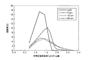
また、表2に示す本発明例と比較例の冷間圧延前の結晶粒度分布を、本発明で定めた方法で円相当直径の個数率を測定し、ヒストグラムを作成し、円相当直径のμmの値を底を10とするlogの値を横軸に取り、縦軸に個数率を取りプロットして得た。その結果を図2および図3に示す。また、図2及び図3におけるデータを表3に示し、発明例及び比較例の磁気特性を表4に示す。 Further, the grain size distribution before cold rolling of the present invention example and the comparative example shown in Table 2 was measured by measuring the number ratio of the equivalent circle diameter by the method defined in the present invention, and a histogram was prepared. The log value with the base value of 10 is taken on the horizontal axis, and the number ratio is plotted on the vertical axis. The results are shown in FIG. 2 and FIG. The data in FIGS. 2 and 3 are shown in Table 3, and the magnetic characteristics of the inventive examples and the comparative examples are shown in Table 4.
なお、測定個数は最低400個以上を測定することとした。これは、結晶粒が粗大であるため、観察視野の偏りによる測定誤差を防ぐためである。さらに好ましくは、700個以上、さらに好ましくは1000個以上の個数を測定して円相当直径の平均値を求めることがより好ましい。 It should be noted that the number of measurement was 400 at least. This is because the crystal grains are coarse so as to prevent measurement errors due to the deviation of the observation field. More preferably, the average value of equivalent circle diameters is determined by measuring 700 or more, more preferably 1000 or more.
図2に示すように、本発明例では、個数率が分布するのに対応した横軸の範囲の中間値よりも、個数率の最大値のピークの横軸の値が小さかったのに対し、繰返し曲げ試験結果の劣った比較例では個数率の最大値のピークの横軸の値が中間値よりも大きいことが判明した。 As shown in FIG. 2, in the example of the present invention, the value of the horizontal axis of the peak of the maximum value of the number ratio was smaller than the intermediate value of the range of the horizontal axis corresponding to the distribution of the number ratio, In the comparative example inferior in the repeated bending test results, it was found that the value on the horizontal axis of the peak of the maximum number ratio was larger than the intermediate value.
この機構については、粒度分布の広がりを表す横軸の広がりが大きくなり、相対的に個数率が分布する範囲が広がり、鋼板の結晶粒に異常粒が混粒していることが原因ではないかと推察している。 About this mechanism, the spread of the horizontal axis representing the spread of the particle size distribution is increased, the range in which the number ratio is relatively distributed is widened, and it may be because abnormal grains are mixed in the crystal grains of the steel sheet. I guess.
(実施例2)
本発明と比較例の冷間圧延前の結晶粒度分布を測定した。
表5に示す成分の鋼からなるスラブを、1100℃で1時間加熱し、熱間仕上温度の平均値FTと巻取温度の平均値CTを変化させ、10分間の自己焼鈍を行った。表6に仕上熱延の際のFT、CT、ΔFT、ΔCTと、JIS C2550により行った繰返し曲げ試験の結果を示す。
(Example 2)
The grain size distribution before cold rolling of the present invention and the comparative example was measured.
A slab made of steel having the components shown in Table 5 was heated at 1100 ° C. for 1 hour, and the average value FT of the hot finishing temperature and the average value CT of the coiling temperature were changed, and self-annealing was performed for 10 minutes. Table 6 shows the results of FT, CT, ΔFT, and ΔCT during finish hot rolling and the results of repeated bending tests performed according to JIS C2550.
リバース圧延機での通板には往復5回以上の繰り返し曲げに耐えることが必要であり、タンデム圧延機での通板には往復10回以上の繰返し曲げに合格することが必要である。表6より、ΔFTとΔCTの範囲が本発明で定めた条件を満たす場合に、繰返し曲げ試験の結果が優れており、冷延の通板が可能であることがわかる。 It is necessary to withstand repeated bending of 5 times or more for reciprocating plates in a reverse rolling mill, and it is necessary to pass repeated bending of 10 or more reciprocations for passing plates in a tandem rolling mill. From Table 6, it can be seen that when the range of ΔFT and ΔCT satisfies the conditions defined in the present invention, the result of the repeated bending test is excellent, and cold-rolling sheet passing is possible.
(実施例3)
本発明と比較例の冷間圧延前の結晶粒度分布を測定した。
表7に示す成分の鋼からなるスラブを、1200℃で1時間加熱し、熱間圧延仕上温度(FT)を950℃にて板厚2.3mmまで熱間仕上圧延を行い、その後、巻取温度(CT)830℃で巻き取った。
Example 3
The grain size distribution before cold rolling of the present invention and the comparative example was measured.
A slab made of steel having the components shown in Table 7 is heated at 1200 ° C. for 1 hour, hot-finished at a hot rolling finish temperature (FT) of 950 ° C. to a thickness of 2.3 mm, and then wound. Winding was performed at a temperature (CT) of 830 ° C.
熱間仕上温度の平均値(FT)及び巻取温度の平均値(CT)と、熱間仕上温度及び巻取温度のぞれぞれの変動幅ΔFTおよびΔCTはそれぞれ98℃、55℃であった。この仕上熱延条件の場合、式2および式3より求まるΔFTおよびΔCTの上限はそれぞれ147℃、60℃であり、式2及び式3の条件を満たした。
The average value of the hot finishing temperature (FT) and the average value of the coiling temperature (CT), and the fluctuation ranges ΔFT and ΔCT of the hot finishing temperature and the coiling temperature were 98 ° C. and 55 ° C., respectively. It was. In the case of this finish hot rolling condition, the upper limits of ΔFT and ΔCT obtained from
比較例として、熱間仕上温度の平均値(FT)1030℃にて板厚2.3mmまで熱間仕上圧延を行い、その後、巻取温度の平均値(CT)830℃で巻き取った。比較例の場合、熱間仕上げ温度及び巻取温度のそれぞれの変動幅ΔFTおよびΔCTは120℃、50℃であり、この仕上焼鈍条件の場合、式2および式3より求まるΔFTおよびΔCTの上限である100℃および39℃を超えており、発明の範囲外であった。
As a comparative example, hot finish rolling was performed up to a plate thickness of 2.3 mm at an average value (FT) of hot finish temperature (FT) of 1030 ° C., and then winding was performed at an average value (CT) of 830 ° C. of coiling temperature. In the case of the comparative example, the variation widths ΔFT and ΔCT of the hot finishing temperature and the coiling temperature are 120 ° C. and 50 ° C., and in the case of this finish annealing condition, the upper limits of ΔFT and ΔCT obtained from
さらに比較例として、同じ成分で自己焼鈍を行わない、熱延仕上温度の平均値FT860℃、巻取温度の平均値CT700℃の非自己焼鈍材を仕上熱延で製造した。非自己焼鈍材の熱間仕上温度及び巻取温度のそれぞれの変動幅ΔFTおよびΔCTは110℃、60℃であり、ΔFTおよびΔCTの上限は式2および式3よりそれぞれの200℃、50℃と導出されるので、非自己焼鈍材のΔCTが本発明の範囲外であり、非自己焼鈍材の仕上熱延条件は本発明の定める仕上熱延条件を満たさない。
Further, as a comparative example, a non-self-annealed material having an average value FT860 ° C. of hot rolling finishing temperature and an average value CT 700 ° C. of coiling temperature without self-annealing with the same components was manufactured by finishing hot rolling. The variation widths ΔFT and ΔCT of the hot finishing temperature and the coiling temperature of the non-self-annealed material are 110 ° C. and 60 ° C., respectively, and the upper limits of ΔFT and ΔCT are 200 ° C. and 50 ° C. from
その後、自己焼鈍材は熱延コイルをその保有熱により、焼鈍温度830℃、焼鈍時間(自己焼鈍時間)を5、10、60分とする条件で自己焼鈍を行い、その後、冷却速度10℃/s以上で200℃以下まで冷却した。非自己焼鈍材は自己焼鈍を行わず後工程を施した。 Thereafter, the self-annealing material is self-annealed under the conditions that the annealing temperature is 830 ° C. and the annealing time (self-annealing time) is 5, 10, 60 minutes by the retained heat of the hot-rolled coil, and then the cooling rate is 10 ° C. / It cooled to 200 degrees C or less by more than s. The non-self-annealed material was subjected to a post-process without performing self-annealing.
その後、酸洗してから板厚0.5mmになるまで冷間圧延を行い、窒素90%、水素10%、露点−40℃の条件で仕上焼鈍温度800℃で30秒均熱し、歪取焼鈍を水素100%露点−40℃の雰囲気中で温度750℃、保持時間2時間の条件で行った。 Thereafter, the steel sheet is pickled and then cold-rolled to a thickness of 0.5 mm, soaked at a finish annealing temperature of 800 ° C. for 30 seconds under the conditions of 90% nitrogen, 10% hydrogen, and dew point of −40 ° C. Was conducted in an atmosphere of hydrogen 100% dew point −40 ° C. under conditions of a temperature of 750 ° C. and a holding time of 2 hours.
なお、通板性を改善するため、熱延仕上温度1030℃材は冷間圧延前に熱延コイルを90℃の熱水中に60分以上つけてコイル全体を70℃以上に暖めた後、ワークロール径110mmのリバース圧延機で冷間圧延を行った。このようにして無方向性電磁鋼板を製造した。 In order to improve the sheet-passability, the hot-rolled finishing temperature of 1030 ° C. was applied to the hot-rolled coil in 90 ° C. hot water for 60 minutes or more before cold rolling, and the entire coil was heated to 70 ° C. or higher. Cold rolling was performed with a reverse rolling mill having a work roll diameter of 110 mm. In this way, a non-oriented electrical steel sheet was produced.
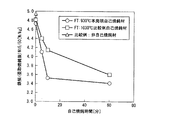
得られた電磁鋼板について、磁束密度と鉄損を測定した。結果を図4及び図5に示す。 About the obtained electromagnetic steel sheet, magnetic flux density and iron loss were measured. The results are shown in FIGS.
図4および図5に示すように、本発明では自己焼鈍時間が15分未満である10分の短時間で磁束密度の向上および鉄損低減が60分の自己焼鈍を施した場合と同じ効果が得られることがわかる。また、本発明の規定する範囲を外れた仕上熱延条件であった自己焼鈍材および、非自己焼鈍材と比較しても磁束密度B50が高く、鉄損W15/50が低く、より優れた磁気特性を示していることがわかる。 As shown in FIGS. 4 and 5, in the present invention, the self-annealing time is less than 15 minutes, the magnetic flux density is improved in a short time of 10 minutes, and the iron loss is reduced by 60 minutes of self-annealing. It turns out that it is obtained. Further, even when compared with the self-annealed material and the non-self-annealed material, which are finish hot-rolling conditions outside the range defined by the present invention, the magnetic flux density B50 is high, the iron loss W15 / 50 is low, and a more excellent magnetic property. It turns out that the characteristic is shown.
(実施例4)
本発明による熱延鋼帯と比較材を出発材とする無方向性電磁鋼板について磁気特性を比較した。
表8に示す成分の鋼A〜Sのスラブを1100℃1時間加熱し、熱延は925℃にて仕上げ、巻取り温度800℃で巻取り、これを1時間自己焼鈍に供した。ΔFTおよびΔCTは式2および式3を満たす95℃(上限162℃)、51℃(上限59℃)に制御して仕上熱延を行った。
JIS C2550に定められた方法で測定したエプスタイン試料の磁気測定結果を表8に示す。
本発明で規定した範囲に成分がおさまる鋼は、比較例よりも優れた磁気特性を示していることがわかる。
(Example 4)
The magnetic properties of the non-oriented electrical steel sheets starting from the hot-rolled steel strip according to the present invention and a comparative material were compared.
Slabs of steels A to S having the components shown in Table 8 were heated at 1100 ° C. for 1 hour, finished with hot rolling at 925 ° C., wound at a winding temperature of 800 ° C., and subjected to self-annealing for 1 hour. ΔFT and ΔCT were controlled to 95 ° C. (upper limit 162 ° C.) and 51 ° C. (upper limit 59 ° C.) satisfying the
Table 8 shows the magnetic measurement results of the Epstein sample measured by the method defined in JIS C2550.
It can be seen that the steel whose components fall within the range defined by the present invention exhibits magnetic properties superior to those of the comparative example.
Claims (7)
C:0.003%以下、
Si:0.1%〜4.5%、
Mn:0.1%〜1.5%、
N:0.003%以下、
S:0.004%以下を含有し、残部がFe及び不純物よりなる成分を有する熱延鋼帯であり、
前記熱延鋼帯の圧延方向と熱延鋼帯の板面垂直方向を含む断面における結晶粒の円相当粒径(μm)を測定し、これを常用対数で表示した結晶粒度分布において、最大粒度と最小粒度の中間値mと、結晶粒数の個数率が最大となる粒度nの間に、以下の関係式(1)が成り立つとともに、前記中間値mは1.287以上であることを特徴とする無方向性電磁鋼板用の熱延鋼帯。
n<m …(1) % By mass
C: 0.003% or less,
Si: 0.1% to 4.5%,
Mn: 0.1% to 1.5%,
N: 0.003% or less
S: A hot-rolled steel strip containing 0.004% or less, with the balance being composed of Fe and impurities ,
In the grain size distribution in which the equivalent grain size (μm) of the crystal grains in the cross section including the rolling direction of the hot-rolled steel strip and the direction perpendicular to the plate surface of the hot-rolled steel strip is measured, The following relational expression (1) holds between the intermediate value m of the minimum particle size and the particle size n that maximizes the number ratio of the number of crystal grains , and the intermediate value m is 1.287 or more. A hot-rolled steel strip for non-oriented electrical steel sheets.
n <m (1)
この際、熱延鋼帯全長にわたる熱延仕上温度の平均値FT(℃)と熱延鋼帯全長における熱延仕上温度の変動ΔFT(℃)が(2)式を満足させるとともに、
熱延鋼帯全長にわたる巻取温度の平均値CT(℃)と熱延鋼帯全長における巻取温度の変動ΔCT(℃)が(3)式を満足させることを特徴とする無方向性電磁鋼板の製造方法。
ΔFT≦−0.589×FT+707 …(2)
ΔCT≦−0.259×(FT−CT)+91 …(3) A steel having the chemical composition according to any one of claims 1 to 3 is hot-finished and rolled at a hot rolling finish temperature of 850 to 950 ° C and wound at a winding temperature of 400 to 950 ° C. A hot-rolled coil comprising the hot-rolled steel strip according to any one of claims 1 to 3 ,
At this time, the average value FT (° C) of the hot rolling finishing temperature over the entire length of the hot-rolled steel strip and the variation ΔFT (° C) of the hot-rolling finishing temperature over the entire length of the hot-rolled steel strip satisfy the formula (2),
Non-oriented electrical steel sheet, characterized in that the mean value CT (° C) of the coiling temperature over the entire length of the hot-rolled steel strip and the variation ΔCT (° C) of the coiling temperature over the entire length of the hot-rolled steel strip satisfy the formula (3) Manufacturing method.
ΔFT ≦ −0.589 × FT + 707 (2)
ΔCT ≦ −0.259 × (FT−CT) +91 (3)
Priority Applications (1)
| Application Number | Priority Date | Filing Date | Title |
|---|---|---|---|
| JP2015217687A JP6620522B2 (en) | 2015-11-05 | 2015-11-05 | Hot rolled steel strip for non-oriented electrical steel sheet and method for producing non-oriented electrical steel sheet |
Applications Claiming Priority (1)
| Application Number | Priority Date | Filing Date | Title |
|---|---|---|---|
| JP2015217687A JP6620522B2 (en) | 2015-11-05 | 2015-11-05 | Hot rolled steel strip for non-oriented electrical steel sheet and method for producing non-oriented electrical steel sheet |
Publications (2)
| Publication Number | Publication Date |
|---|---|
| JP2017088930A JP2017088930A (en) | 2017-05-25 |
| JP6620522B2 true JP6620522B2 (en) | 2019-12-18 |
Family
ID=58768199
Family Applications (1)
| Application Number | Title | Priority Date | Filing Date |
|---|---|---|---|
| JP2015217687A Active JP6620522B2 (en) | 2015-11-05 | 2015-11-05 | Hot rolled steel strip for non-oriented electrical steel sheet and method for producing non-oriented electrical steel sheet |
Country Status (1)
| Country | Link |
|---|---|
| JP (1) | JP6620522B2 (en) |
Cited By (1)
| Publication number | Priority date | Publication date | Assignee | Title |
|---|---|---|---|---|
| EP4296380A4 (en) * | 2021-02-19 | 2024-06-12 | Nippon Steel Corporation | HOT-ROLLED STEEL SHEET FOR NON-ORIENTED ELECTROMAGNETIC STEEL SHEET AS WELL AS METHOD FOR MANUFACTURING THE SAME |
Families Citing this family (7)
| Publication number | Priority date | Publication date | Assignee | Title |
|---|---|---|---|---|
| CN114008224A (en) * | 2019-06-28 | 2022-02-01 | 杰富意钢铁株式会社 | Method for manufacturing non-oriented electromagnetic steel sheet, method for manufacturing motor core, and motor core |
| KR102749424B1 (en) * | 2019-11-15 | 2025-01-03 | 닛폰세이테츠 가부시키가이샤 | Non-oriented electrical steel sheet |
| JP7678363B2 (en) * | 2021-02-19 | 2025-05-16 | 日本製鉄株式会社 | Hot-rolled steel sheet for non-oriented electrical steel sheet, manufacturing method for hot-rolled steel sheet for non-oriented electrical steel sheet, and manufacturing method for non-oriented electrical steel sheet |
| CN117098617A (en) * | 2021-03-31 | 2023-11-21 | 日本制铁株式会社 | Non-oriented electromagnetic steel plate, punching method of non-oriented electromagnetic steel plate and die for blanking non-oriented electromagnetic steel plate |
| CN114427023B (en) * | 2022-01-13 | 2023-08-25 | 武汉钢铁有限公司 | Method for improving performance uniformity of low-grade non-oriented silicon steel in conventional process |
| TWI817398B (en) * | 2022-03-18 | 2023-10-01 | 中國鋼鐵股份有限公司 | Electrical steel sheet and method for producing the same |
| KR102811640B1 (en) * | 2022-07-27 | 2025-05-26 | 현대제철 주식회사 | Non-oriented electrical steel sheet and method for manufacturing the same |
Family Cites Families (8)
| Publication number | Priority date | Publication date | Assignee | Title |
|---|---|---|---|---|
| JPS5476422A (en) * | 1977-11-30 | 1979-06-19 | Nippon Steel Corp | Manufacture of non-oriented electrical sheet with superior magnetism by self annealing of hot rolled sheet |
| JPS62222022A (en) * | 1986-03-20 | 1987-09-30 | Nippon Steel Corp | Manufacture of nonoriented electrical sheet having good brittleness resistance and magnetic characteristic after stress relief annealing |
| IT1237481B (en) * | 1989-12-22 | 1993-06-07 | Sviluppo Materiali Spa | PROCEDURE FOR THE PRODUCTION OF SEMI-FINISHED NON-ORIENTED WHEAT MAGNETIC SHEET. |
| JP3399726B2 (en) * | 1995-11-07 | 2003-04-21 | 新日本製鐵株式会社 | Manufacturing method of non-oriented electrical steel sheet with high magnetic flux density and low iron loss |
| JP4337159B2 (en) * | 1999-02-02 | 2009-09-30 | Jfeスチール株式会社 | Manufacturing method of silicon steel sheet and hot rolled steel strip material for silicon steel sheet |
| JP2005200756A (en) * | 2004-01-19 | 2005-07-28 | Sumitomo Metal Ind Ltd | Method for producing non-oriented electrical steel sheet |
| JP5375149B2 (en) * | 2008-09-11 | 2013-12-25 | Jfeスチール株式会社 | Non-oriented electrical steel sheet and manufacturing method thereof |
| PL2778244T3 (en) * | 2011-11-11 | 2020-08-10 | Nippon Steel Corporation | Manufacturing method of non-oriented electrical steel sheet |
-
2015
- 2015-11-05 JP JP2015217687A patent/JP6620522B2/en active Active
Cited By (2)
| Publication number | Priority date | Publication date | Assignee | Title |
|---|---|---|---|---|
| EP4296380A4 (en) * | 2021-02-19 | 2024-06-12 | Nippon Steel Corporation | HOT-ROLLED STEEL SHEET FOR NON-ORIENTED ELECTROMAGNETIC STEEL SHEET AS WELL AS METHOD FOR MANUFACTURING THE SAME |
| US12529118B2 (en) | 2021-02-19 | 2026-01-20 | Nippon Steel Corporation | Hot rolled steel sheet for non oriented electrical steel sheet and producing method thereof |
Also Published As
| Publication number | Publication date |
|---|---|
| JP2017088930A (en) | 2017-05-25 |
Similar Documents
| Publication | Publication Date | Title |
|---|---|---|
| JP6620522B2 (en) | Hot rolled steel strip for non-oriented electrical steel sheet and method for producing non-oriented electrical steel sheet | |
| JP5262012B2 (en) | High carbon hot rolled steel sheet and manufacturing method thereof | |
| JP5712863B2 (en) | Method for producing non-oriented electrical steel sheet | |
| JP5050433B2 (en) | Method for producing extremely soft high carbon hot-rolled steel sheet | |
| JP7010418B1 (en) | High-strength hot-rolled steel sheet and its manufacturing method | |
| JP6082451B2 (en) | Steel sheet for hot pressing and manufacturing method thereof | |
| WO2017170611A1 (en) | Nb-containing ferritic stainless steel sheet and manufacturing method therefor | |
| JP6119928B1 (en) | Cold rolled steel sheet and method for producing the same | |
| CN103562425A (en) | High carbon thin steel sheet and method for producing same | |
| JP5093029B2 (en) | Cold rolled steel sheet and method for producing the same | |
| JP6070616B2 (en) | Manufacturing method of hot-rolled steel sheet | |
| JP2020033640A (en) | Production method of non-oriented electromagnetic steel sheet | |
| JPWO2020067236A1 (en) | Manufacturing method of grain-oriented electrical steel sheet and cold rolling equipment | |
| JP6950723B2 (en) | Manufacturing method of grain-oriented electrical steel sheet | |
| CN114651079A (en) | Non-oriented electromagnetic steel sheet | |
| JP5381690B2 (en) | Manufacturing method of high carbon hot rolled steel sheet | |
| JP6519012B2 (en) | Low carbon steel sheet excellent in cold formability and toughness after heat treatment and manufacturing method | |
| JP3800902B2 (en) | High carbon steel sheet for processing with small in-plane anisotropy and method for producing the same | |
| JP7636703B2 (en) | Non-oriented electrical steel sheet | |
| JP2015137422A (en) | Hot-rolled steel sheet and manufacturing method thereof | |
| JP7284392B2 (en) | Manufacturing method of grain-oriented electrical steel sheet | |
| JP5716760B2 (en) | Cold rolled steel sheet manufacturing method | |
| CN119895065A (en) | Non-oriented electromagnetic steel sheet | |
| JP6524716B2 (en) | Method of manufacturing hot rolled steel sheet excellent in workability | |
| JP7284367B2 (en) | Non-oriented electrical steel sheet coil and its manufacturing method |
Legal Events
| Date | Code | Title | Description |
|---|---|---|---|
| A621 | Written request for application examination |
Free format text: JAPANESE INTERMEDIATE CODE: A621 Effective date: 20180704 |
|
| RD03 | Notification of appointment of power of attorney |
Free format text: JAPANESE INTERMEDIATE CODE: A7423 Effective date: 20181019 |
|
| A977 | Report on retrieval |
Free format text: JAPANESE INTERMEDIATE CODE: A971007 Effective date: 20190514 |
|
| A131 | Notification of reasons for refusal |
Free format text: JAPANESE INTERMEDIATE CODE: A131 Effective date: 20190618 |
|
| A521 | Written amendment |
Free format text: JAPANESE INTERMEDIATE CODE: A523 Effective date: 20190809 |
|
| TRDD | Decision of grant or rejection written | ||
| A01 | Written decision to grant a patent or to grant a registration (utility model) |
Free format text: JAPANESE INTERMEDIATE CODE: A01 Effective date: 20191023 |
|
| A61 | First payment of annual fees (during grant procedure) |
Free format text: JAPANESE INTERMEDIATE CODE: A61 Effective date: 20191105 |
|
| R151 | Written notification of patent or utility model registration |
Ref document number: 6620522 Country of ref document: JP Free format text: JAPANESE INTERMEDIATE CODE: R151 |