JP6618467B2 - Integrated galleryless piston and its construction method - Google Patents
Integrated galleryless piston and its construction method Download PDFInfo
- Publication number
- JP6618467B2 JP6618467B2 JP2016528166A JP2016528166A JP6618467B2 JP 6618467 B2 JP6618467 B2 JP 6618467B2 JP 2016528166 A JP2016528166 A JP 2016528166A JP 2016528166 A JP2016528166 A JP 2016528166A JP 6618467 B2 JP6618467 B2 JP 6618467B2
- Authority
- JP
- Japan
- Prior art keywords
- piston
- area
- lower crown
- percent
- dimensional
- Prior art date
- Legal status (The legal status is an assumption and is not a legal conclusion. Google has not performed a legal analysis and makes no representation as to the accuracy of the status listed.)
- Expired - Fee Related
Links
Images


Classifications
-
- F—MECHANICAL ENGINEERING; LIGHTING; HEATING; WEAPONS; BLASTING
- F02—COMBUSTION ENGINES; HOT-GAS OR COMBUSTION-PRODUCT ENGINE PLANTS
- F02F—CYLINDERS, PISTONS OR CASINGS, FOR COMBUSTION ENGINES; ARRANGEMENTS OF SEALINGS IN COMBUSTION ENGINES
- F02F3/00—Pistons
- F02F3/0084—Pistons the pistons being constructed from specific materials
- F02F3/0092—Pistons the pistons being constructed from specific materials the material being steel-plate
-
- F—MECHANICAL ENGINEERING; LIGHTING; HEATING; WEAPONS; BLASTING
- F02—COMBUSTION ENGINES; HOT-GAS OR COMBUSTION-PRODUCT ENGINE PLANTS
- F02F—CYLINDERS, PISTONS OR CASINGS, FOR COMBUSTION ENGINES; ARRANGEMENTS OF SEALINGS IN COMBUSTION ENGINES
- F02F3/00—Pistons
- F02F3/16—Pistons having cooling means
-
- B—PERFORMING OPERATIONS; TRANSPORTING
- B23—MACHINE TOOLS; METAL-WORKING NOT OTHERWISE PROVIDED FOR
- B23P—METAL-WORKING NOT OTHERWISE PROVIDED FOR; COMBINED OPERATIONS; UNIVERSAL MACHINE TOOLS
- B23P15/00—Making specific metal objects by operations not covered by a single other subclass or a group in this subclass
- B23P15/10—Making specific metal objects by operations not covered by a single other subclass or a group in this subclass pistons
-
- F—MECHANICAL ENGINEERING; LIGHTING; HEATING; WEAPONS; BLASTING
- F02—COMBUSTION ENGINES; HOT-GAS OR COMBUSTION-PRODUCT ENGINE PLANTS
- F02F—CYLINDERS, PISTONS OR CASINGS, FOR COMBUSTION ENGINES; ARRANGEMENTS OF SEALINGS IN COMBUSTION ENGINES
- F02F3/00—Pistons
-
- F—MECHANICAL ENGINEERING; LIGHTING; HEATING; WEAPONS; BLASTING
- F02—COMBUSTION ENGINES; HOT-GAS OR COMBUSTION-PRODUCT ENGINE PLANTS
- F02F—CYLINDERS, PISTONS OR CASINGS, FOR COMBUSTION ENGINES; ARRANGEMENTS OF SEALINGS IN COMBUSTION ENGINES
- F02F3/00—Pistons
- F02F3/0015—Multi-part pistons
- F02F3/0069—Multi-part pistons the crown and skirt being interconnected by the gudgeon pin
-
- F—MECHANICAL ENGINEERING; LIGHTING; HEATING; WEAPONS; BLASTING
- F02—COMBUSTION ENGINES; HOT-GAS OR COMBUSTION-PRODUCT ENGINE PLANTS
- F02F—CYLINDERS, PISTONS OR CASINGS, FOR COMBUSTION ENGINES; ARRANGEMENTS OF SEALINGS IN COMBUSTION ENGINES
- F02F3/00—Pistons
- F02F2003/0007—Monolithic pistons; One piece constructions; Casting of pistons
-
- Y—GENERAL TAGGING OF NEW TECHNOLOGICAL DEVELOPMENTS; GENERAL TAGGING OF CROSS-SECTIONAL TECHNOLOGIES SPANNING OVER SEVERAL SECTIONS OF THE IPC; TECHNICAL SUBJECTS COVERED BY FORMER USPC CROSS-REFERENCE ART COLLECTIONS [XRACs] AND DIGESTS
- Y10—TECHNICAL SUBJECTS COVERED BY FORMER USPC
- Y10T—TECHNICAL SUBJECTS COVERED BY FORMER US CLASSIFICATION
- Y10T29/00—Metal working
- Y10T29/49—Method of mechanical manufacture
- Y10T29/49229—Prime mover or fluid pump making
- Y10T29/49249—Piston making
- Y10T29/49265—Ring groove forming or finishing
Landscapes
- Engineering & Computer Science (AREA)
- Mechanical Engineering (AREA)
- Chemical & Material Sciences (AREA)
- Combustion & Propulsion (AREA)
- General Engineering & Computer Science (AREA)
- Pistons, Piston Rings, And Cylinders (AREA)
Description
関連出願の相互参照
本願は、2013年11月7日に提出された米国仮出願連続番号第61/901,287号の利点と、2014年6月13日に提出された米国仮出願連続番号第62/011,876号の利点と、2014年11月7日に提出された米国実用新案連続番号第14/535,839号の利点とを主張するものであり、それら全体が引用によりこの明細書中に援用されている。
CROSS REFERENCE TO RELATED APPLICATIONS This application is based on the advantages of US Provisional Application Serial No. 61 / 901,287, filed November 7, 2013, and US Provisional Application Serial Number, filed June 13, 2014. No. 62 / 011,876 and the advantages of US Utility Model Serial No. 14 / 535,839 filed Nov. 7, 2014, all of which are incorporated herein by reference. Incorporated inside.
発明の背景
1.技術分野
この発明は概して内燃機関に関し、より特定的には、そのためのピストンに関する。
BACKGROUND OF THE INVENTION TECHNICAL FIELD This invention relates generally to internal combustion engines, and more particularly to pistons therefor.
2.関連技術
エンジン製造業者は、エンジン効率および性能を向上せよとの要求の高まりに直面している。エンジン効率および性能の向上は、製造に関する費用の削減と同時に、燃費向上、オイル消費の削減、燃料系統の向上、シリンダボア内の圧縮負荷および動作温度の上昇、ピストンによる熱損失の低減、構成部品同士の潤滑の向上、エンジン軽量化、ならびにエンジン小型化を含むが、これらに限定されない。燃焼室内の圧縮負荷および動作温度を上昇させることが所望されている一方で、実行可能な限度内でピストンの温度を維持することが依然として必要とされている。したがって、燃焼室内の圧縮負荷および動作温度を上昇させることが所望されているが、この目的を達成するには何らかの妥協が付随してくる。すなわち、これらの望ましい「上昇」によって、ピストンの圧縮高さと、これにより全体的なピストンの大きさおよび質量とを低減させることのできる度合いが制限されてしまう。このような制限は、ピストンの動作温度を下げるのに必要と見なされる閉鎖型または部分閉鎖型の冷却ギャラリを有する典型的なピストン構造の場合に特に問題となる。さらに、閉鎖型または部分的閉鎖型の冷却ギャラリを形成するのに上方部分と下方部分とが接合継手に沿って接合されているピストンを製造するためのコストは、一般に、上方部分と下方部分とを接着するのに用いられる接合プロセスのせいで、高くなってしまう。さらに、ピストンに加えられる機械的負荷および熱負荷の増大に耐えることができるようにするために、上述の「冷却ギャラリ付きの」ピストンを鋼から製造する必要があるので、エンジンを軽量化することのできる度合いが影響を受けることとなる。
2. Related Art Engine manufacturers are facing increasing demands to improve engine efficiency and performance. Improvements in engine efficiency and performance can be achieved by reducing manufacturing costs as well as improving fuel economy, reducing oil consumption, improving fuel system, increasing compression load and operating temperature in the cylinder bore, reducing heat loss due to pistons, This includes, but is not limited to, improved lubrication, engine weight reduction, and engine size reduction. While it is desirable to increase the compression load and operating temperature in the combustion chamber, there is still a need to maintain the temperature of the piston within feasible limits. Therefore, it is desirable to increase the compression load and operating temperature in the combustion chamber, but some compromise is associated with achieving this goal. That is, these desirable “rises” limit the degree to which the compression height of the piston and thereby the overall piston size and mass can be reduced. Such limitations are particularly problematic in the case of typical piston structures having a closed or partially closed cooling gallery that is deemed necessary to reduce the operating temperature of the piston. Further, the cost of producing a piston in which the upper and lower portions are joined along a joint joint to form a closed or partially closed cooling gallery is generally between the upper and lower portions. Due to the bonding process used to bond the material, it becomes expensive. In addition, to make it possible to withstand the increased mechanical and thermal loads applied to the piston, it is necessary to make the aforementioned "cooled gallery" piston out of steel, thus reducing the weight of the engine The degree of ability to be affected will be affected.
この発明に従って構築されるピストンは、この明細書中における開示を理解し、添付の図面を観察することで当業者にとって明らかになるように、公知のピストン構造が持つ上述の不利点および他の不利点を克服するものである。 Pistons constructed in accordance with the present invention have the aforementioned disadvantages and other disadvantages of known piston structures, as will be apparent to those skilled in the art upon understanding the disclosure herein and observing the accompanying drawings. It overcomes the advantages.
発明の概要
この発明に従って構築されるピストンは一塊りの鋼から構成され、これにより、現代の高性能エンジンにおいて見られるような負荷および温度などの、シリンダボア内における圧縮負荷および温度の上昇に耐えるように、強度および耐久性の高いピストンが提供される。さらに、ピストンが新しい単一部品構成であることにより、ピストンの製造に伴う費用が低減される。なぜなら、ピストンの上方部分と下方部分とを接合するのに用いられてきた典型的なプロセスが採用されていないからである。さらに、本発明に従って構築されるピストンにおいては、閉鎖型または部分的閉鎖型の冷却ギャラリを含むピストンと比べて、ピストンのコンプレッションハイト(CH:compression height)および重量を著しく小さくすることができる。これは特に、冷却ギャラリを形成するために一般に用いられる床の存在がピストンから省かれており、これにより、ピストンが内部に配置されているエンジンをより小型、より軽量かつより低燃費に構成することが可能になるからである。
SUMMARY OF THE INVENTION A piston constructed in accordance with the present invention is constructed of a lump of steel so that it can withstand compression loads and temperature increases in a cylinder bore, such as loads and temperatures found in modern high performance engines. In addition, a piston having high strength and durability is provided. In addition, the new single piece construction of the piston reduces the costs associated with manufacturing the piston. This is because the typical process that has been used to join the upper and lower portions of the piston is not employed. Furthermore, pistons constructed in accordance with the present invention can have a significantly reduced compression height (CH) and weight of the piston as compared to a piston that includes a closed or partially closed cooling gallery. In particular, the presence of a floor commonly used to form a cooling gallery is omitted from the piston, thereby making the engine in which the piston is located smaller, lighter and more fuel efficient. Because it becomes possible.
本発明の一態様に従うと、内燃機関のためのギャラリなしピストンが提供される。ピストンは一体型のピストン本体を有する。この一体型のピストン本体は中心の長手方向軸に沿って延在する。この中心の長手方向軸に沿って、ピストンが内燃機関のシリンダボア内で往復運動する。ピストン本体は、上部燃焼面を形成する上方壁を有し、環状リングベルト領域が、少なくとも1つのピストンリングを収容するために上部燃焼面から垂下している。ピストン本体はさらに、リングベルト領域から垂下してシリンダボア内においてピストンを案内し易くするための1対のスカート部分と、横方向に間隔を空けて配置された1対のピンボアを備える1対のピンボスとを含む。1対のピンボアは、ピンボア軸に沿って位置合わせされてリストピンを収容するためのものである。上部燃焼面は第1の部分および第2の部分を有する。第1の部分は、上方壁の外周に沿って環状に延在する。第2の部分は、第1の部分から径方向内側に垂下する燃焼ボウルを形成する。上方壁は、上部燃焼面の第2の部分の正反対側において燃焼ボウルの下側に形成された下クラウン面を有する。下クラウン面は、中心の長手方向軸に沿って見たときに、開放的に露出された突出型の2次元表面積を有し、突出型の2次元表面積は、ピストン本体の最大外径によって規定される面積の約35パーセント〜約60パーセントであり、これにより、跳ねかかってくるオイルまたは吹きかけられるオイルが自由に接触できる面積を広くして、使用中のピストンの冷却を向上させる。 According to one aspect of the invention, a galleryless piston for an internal combustion engine is provided. The piston has an integral piston body. The integral piston body extends along a central longitudinal axis. A piston reciprocates within the cylinder bore of the internal combustion engine along this central longitudinal axis. The piston body has an upper wall that forms an upper combustion surface and an annular ring belt region depends from the upper combustion surface to accommodate at least one piston ring. The piston body further includes a pair of pin bosses that includes a pair of skirt portions depending from the ring belt region to facilitate guiding the piston within the cylinder bore and a pair of pin bores spaced laterally. Including. The pair of pin bores are aligned along the pin bore axis to accommodate the wrist pins. The upper combustion surface has a first portion and a second portion. The first portion extends annularly along the outer periphery of the upper wall. The second part forms a combustion bowl that hangs radially inward from the first part. The upper wall has a lower crown surface formed on the underside of the combustion bowl on the opposite side of the second portion of the upper combustion surface. The lower crown surface, when viewed along the central longitudinal axis, has a protruding two-dimensional surface area exposed openly, which is defined by the maximum outer diameter of the piston body. About 35 percent to about 60 percent of the area taken up, thereby increasing the area that the splashing or sprayed oil can freely contact to improve the cooling of the piston in use.
本発明の別の態様に従うと、下クラウン面は、ピストン本体の面積の40パーセントよりも広い総3次元表面積を有する。 According to another aspect of the invention, the lower crown surface has a total three-dimensional surface area that is greater than 40 percent of the area of the piston body.
本発明の別の態様に従うと、下クラウン面は、ピストン本体の面積の約40パーセント〜約90パーセントであり得る総3次元表面積を有する。 In accordance with another aspect of the present invention, the lower crown surface has a total three-dimensional surface area that can be about 40 percent to about 90 percent of the area of the piston body.
本発明の別の態様に従うと、下クラウン面は、ピストン本体の最大外径の約75パーセント〜約90パーセントの直径を有する。 According to another aspect of the invention, the lower crown surface has a diameter of about 75 percent to about 90 percent of the maximum outer diameter of the piston body.
本発明の別の態様に従うと、燃焼ボウルは最大燃焼ボウル直径を有し、下クラウン面は、最大燃焼ボウル直径の少なくとも85パーセントの直径を有する。 According to another aspect of the invention, the combustion bowl has a maximum combustion bowl diameter and the lower crown surface has a diameter of at least 85 percent of the maximum combustion bowl diameter.
本発明の別の態様に従うと、下クラウン面は、最大燃焼ボウル直径の100パーセント〜140パーセントの直径を有し得る。 In accordance with another aspect of the present invention, the lower crown surface can have a diameter of 100 percent to 140 percent of the maximum combustion bowl diameter.
本発明の別の態様に従うと、ピストン本体は、ピンボスからピンボア軸に沿ってリングベルト領域にまで径方向外側に延在する1対のポケットを有する。1対のポケットは、少なくとも下クラウン面の一部、第1の部分の下側の一部、および環状リングベルト領域の内面の一部を規定する。ポケットは、ピストン本体の最大2次元面積の約45パーセント〜約85パーセントの総3次元表面積を有し得る。 According to another aspect of the invention, the piston body has a pair of pockets extending radially outward from the pin boss along the pin bore axis to the ring belt region. The pair of pockets defines at least a portion of the lower crown surface, a portion of the lower portion of the first portion, and a portion of the inner surface of the annular ring belt region. The pocket may have a total three-dimensional surface area of about 45 percent to about 85 percent of the maximum two-dimensional area of the piston body.
本発明の別の態様に従うと、ポケットは、ピストン本体の最大2次元面積の60パーセントよりも広い総3次元表面積を有し得る。 According to another aspect of the present invention, the pocket may have a total three-dimensional surface area that is greater than 60 percent of the maximum two-dimensional area of the piston body.
本発明の別の態様に従うと、ポケットは、ピストン本体の最大2次元面積の70パーセントよりも広い総3次元表面積を有し得る。 In accordance with another aspect of the present invention, the pocket may have a total three-dimensional surface area that is greater than 70 percent of the maximum two-dimensional area of the piston body.
本発明の別の態様に従うと、ピンボスは、ピストン本体の最大外径の60パーセント未満である第1の距離だけ、ピンボア軸に沿って互いから間隔を空けて配置された径方向最外面を有し得る。 In accordance with another aspect of the invention, the pin boss has a radially outermost surface spaced from each other along the pin bore axis by a first distance that is less than 60 percent of the maximum outer diameter of the piston body. Can do.
本発明の別の態様に従うと、内燃機関のためのギャラリなしピストンを構築する方法が提供される。当該方法は、機械加工プロセス、鍛造プロセスまたは鋳造プロセスのうちの1つのプロセスにおいて一体型のピストン本体を形成するステップを含む。ピストン本体は、上部燃焼面を備えた上方壁と、上部燃焼面から垂下する環状リングベルト領域とを有する。第1の部分および第2の部分を有する上部燃焼面が形成される。第1の部分は、上方壁の外周に沿って環状に延在する。第2の部分は、第1の部分から径方向内側に垂下する燃焼ボウルを形成する。第2の部分の正反対側において燃焼ボウルの下側に下クラウン面を有する上方壁が形成される。環状リングベルト領域から垂下する1対のスカート部分と、横方向に間隔を空けて配置された1対のピンボアとを有するピストン本体がさらに形成される。横方向に間隔を空けて配置された1対のピンボアは、ピンボア軸に沿って位置合わせされてリストピンを収容するためのものである。中心の長手方向軸に沿って見たときに、開放的に視認可能な突出型の2次元表面積を有する下クラウン面が形成される。突出型の2次元表面積は、ピストン本体の最大外径によって規定される面積の約35パーセント〜約60パーセントである。 According to another aspect of the present invention, a method for constructing a galleryless piston for an internal combustion engine is provided. The method includes forming an integral piston body in one of a machining process, a forging process or a casting process. The piston body has an upper wall with an upper combustion surface and an annular ring belt region depending from the upper combustion surface. An upper combustion surface having a first portion and a second portion is formed. The first portion extends annularly along the outer periphery of the upper wall. The second part forms a combustion bowl that hangs radially inward from the first part. An upper wall having a lower crown surface on the underside of the combustion bowl is formed on the opposite side of the second portion. A piston body is further formed having a pair of skirt portions depending from the annular ring belt region and a pair of pin bores spaced laterally. A pair of pin bores spaced apart in the transverse direction are aligned along the pin bore axis to accommodate the wrist pins. A lower crown surface is formed having a projecting two-dimensional surface area that is openly visible when viewed along the central longitudinal axis. The protruding two-dimensional surface area is about 35 percent to about 60 percent of the area defined by the maximum outer diameter of the piston body.
本発明の別の態様に従うと、当該方法は、ピストン本体の面積の40パーセントよりも広い総3次元表面積を有する下クラウン面を形成するステップを含む。 According to another aspect of the invention, the method includes forming a lower crown surface having a total three-dimensional surface area greater than 40 percent of the area of the piston body.
本発明の別の態様に従うと、当該方法は、ピストン本体の面積の約40パーセント〜約90パーセントである総3次元表面積を有する下クラウン面を形成するステップを含む。 In accordance with another aspect of the invention, the method includes forming a lower crown surface having a total three-dimensional surface area that is about 40 percent to about 90 percent of the area of the piston body.
本発明の別の態様に従うと、当該方法はさらに、ピストン本体の面積の50パーセントよりも広い総3次元表面積を有する下クラウン面を形成するステップを含み得る。 According to another aspect of the invention, the method may further include forming a lower crown surface having a total three-dimensional surface area greater than 50 percent of the area of the piston body.
本発明の別の態様に従うと、当該方法は、ピストン本体の最大外径の約75パーセント〜約90パーセントの直径を有する下クラウン面を形成するステップを含む。 According to another aspect of the invention, the method includes forming a lower crown surface having a diameter of about 75 percent to about 90 percent of the maximum outer diameter of the piston body.
本発明の別の態様に従うと、当該方法はさらに、燃焼ボウルの最大径の少なくとも85パーセントである直径を有する下クラウン面を形成するステップを含み得る。 In accordance with another aspect of the present invention, the method may further include forming a lower crown surface having a diameter that is at least 85 percent of the maximum diameter of the combustion bowl.
本発明の別の態様に従うと、当該方法はさらに、最大燃焼ボウル直径の100パーセント〜140パーセントである直径を有する下クラウン面を形成するステップを含み得る。 According to another aspect of the invention, the method may further include forming a lower crown surface having a diameter that is between 100 percent and 140 percent of the maximum combustion bowl diameter.
本発明の別の態様に従うと、当該方法は、機械加工プロセス、鍛造プロセスまたは鋳造プロセスにおいて1対のポケットを形成するステップをさらに含み得る。ポケットは、ピンボスからピンボア軸に沿ってリングベルト領域にまで径方向外側に延在する。ポケットは、少なくとも下クラウン面の一部、第1の部分の下側の一部、および環状リングベルト領域の内面の一部を規定する。ポケットは、ピストン本体の最大2次元面積の約45パーセント〜約85パーセントの総3次元表面積を有する。 According to another aspect of the invention, the method may further include forming a pair of pockets in a machining process, a forging process or a casting process. The pocket extends radially outward from the pin boss along the pin bore axis to the ring belt region. The pocket defines at least a portion of the lower crown surface, a portion of the lower portion of the first portion, and a portion of the inner surface of the annular ring belt region. The pocket has a total three-dimensional surface area of about 45 percent to about 85 percent of the maximum two-dimensional area of the piston body.
本発明の別の態様に従うと、当該方法はさらに、ピストン本体の最大外径の60パーセント未満である第1の距離だけ、ピンボア軸に沿って互いから間隔を空けて配置された径方向最外面を有するピンボスを形成するステップを含み得る。 According to another aspect of the invention, the method further includes radially outermost surfaces spaced from each other along the pin bore axis by a first distance that is less than 60 percent of the maximum outer diameter of the piston body. Forming a pin boss having:
図面の簡単な説明
本発明のこれらおよび他の局面、特徴および利点は、現在好ましい実施例および最良モードについての以下の詳細な説明、添付の特許請求の範囲および添付の図面に関連付けて検討されると、より容易に認識されるだろう。
BRIEF DESCRIPTION OF THE DRAWINGS These and other aspects, features and advantages of the present invention will be discussed in connection with the following detailed description of the presently preferred embodiments and best mode, the appended claims and the accompanying drawings. Will be more easily recognized.
現在好ましい実施例の詳細な説明
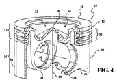
図面をより詳細に参照すると、図1〜図4は、本発明の現在好ましい一実施例に従って構築されたピストン10を示しており、このピストン10は、たとえば、最新のコンパクトで高性能な車両エンジンなどの内燃機関のシリンダボアまたはチャンバ(図示せず)において往復運動させられる。機械加工、鍛造または鋳造などによって一体型材料から形成される一体型本体12を有するピストン10が構築される。その後、場合によっては、必要に応じて仕上げ加工が実行されて、構築を完了させる。したがって、冷却ギャラリ床によって囲まれているかまたは部分的に囲まれている密閉型または部分的密閉型の冷却ギャラリを備えたピストンの場合には一般的である、互いに連結された上方部分および下方部分などの複数の連結された部品が、ピストン10には備わっていない。逆に、ピストン10は、冷却ギャラリを囲むかもしくは部分的に囲む冷却ギャラリ床または他の特徴を持たない点で「ギャラリなし(galleryless)」である。鋼でできたピストン本体12は、現在の高性能な内燃機関の高性能要求(すなわち高い温度および高い圧縮負荷)を満たすために強固で耐久性がある。本体を構築するのに用いられる鋼(すなわち鋼合金)は、特定のエンジン応用例におけるピストン10の要件に応じて、SAE4140等級などであってもよい。本体12の新しい構成は、ピストン10にギャラリがないせいで、以下に記載する特徴の中でも特に、ピストン10の重量およびコンプレッションハイト(CH)を最小限にし、これにより、ピストン10が内部に配置されているエンジンを軽量化し、より小型化することを可能にする。さらに、ギャラリなしであっても、以下において説明され、図面に示される新しい構成により、ピストン10が、最も厳密な動作温度に耐えるように使用中に十分に冷却されることが可能となる。
Detailed Description of the Presently Preferred Embodiment Referring to the drawings in more detail, FIGS. 1-4 show a
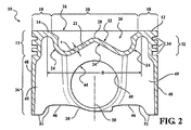
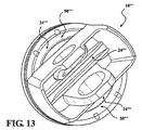
ピストン本体12は、上部ヘッドまたは頂部区域13を有する。頂部区域13は、上方壁14とも称される上壁を提供する。上方壁14は、内燃機関のシリンダボア内の燃焼ガスに直接晒される上部燃焼面16を提供する。上部燃焼面16は、上方壁14の外周に沿って延在する実質的に平坦面として形成される環状の第1の部分18と、上方壁14の燃焼ボウル壁部分21によって規定される第2の部分20とを含む。第2の部分20は非平面の波形面22を有する。非平面の波形面22は、平坦な第1の部分18から垂下し、燃焼ボウル壁部分21の最上面に沿って延在する。下クラウン面24は、上部燃焼面16の第2の部分20の反対側において燃焼ボウル壁部分21の下側に形成される。下クラウン24は、ここでは、底部からピストンを真っすぐに見たときに、ピンボア40を除いて、視認可能な表面となるように規定される。下クラウン面24は、上部燃焼面16の第2の部分20から、燃焼ボウル壁部分21の最小厚さ(t)の2倍以下の距離だけ遠ざかるように延在する。したがって、下クラウン面24は、概して、燃焼ボウル26までの距離が最小となるように燃焼ボウル26の第2の部分20にぴったりとフィットした形状であり、実質的には、燃焼ボウル壁部分21の波形面22とは反対側の表面をなす。下クラウン面24、24′、24′′、24′′′、24′′′′、24′′′′′は、ピストン10(図1〜図4)、10′(図5〜図8)、10′′(図9〜図12)、10′′′(図13および図14)、10′′′′(図15および図16)、10′′′′′(図17および図18)の下側から見ると開放的に露出されており、密閉型もしくは部分的密閉型の冷却ギャラリによって囲まれておらず、または、下クラウン面24、24′、24′′、24′′′、24′′′′、24′′′′′付近でオイルまたは冷却流体を保持する傾向のある他の如何なる特徴によっても囲まれていない。
The
上方壁14の環状の第1の部分18は、上方壁14の外周を形成し、そこから垂下する環状の燃焼ボウル26を囲んでいる。このため、燃焼ボウル26は、上部燃焼面16の最上部にある第1の部分18よりも下方に窪んでいる。中心ピーク28とも称される上方頂部をもたらすような輪郭をした燃焼ボウル26が図示される。中心ピーク28は、ピストン10の中心軸30に沿って同軸に位置してもよく、または、ピストン中心軸30に対して径方向にオフセットされていてもよい。頂部区域13はさらに、1つ以上の対応するピストンリング(図示せず)を収容するための1つ以上のリング溝34をもたらすために上部燃焼面16から垂下するリングベルト領域32を形成する。
An annular
ピストン本体12はさらに底部区域36を含む。底部区域36は、上方区域13から、および概して上方壁14から垂下する1対のピンボス38を含む。ピンボス38は各々、ピンボア40を有し、鉄骨構造の場合には好ましくはギャラリなしである。ピンボア40は、中心の長手方向軸30に対して概して交差して延びるピンボア軸42に沿って同軸に、互いから横方向に間隔を空けて配置される。ピンボス38は、外面43と称されるほぼ平坦な径方向に最も外側の面を有しており、これら外面43は、ピンボア軸40に沿って互いから距離PBを空けて配置され、互いに対してほぼ平行となるように示されている。この場合、PB寸法は最小限にされ、これにより、以下ポケット50と称される概してカップ状の窪んだ領域の露出面積が最大限にされる。これらポケット50は、概してピンボア軸40に沿ってピンボス38の径方向外側に延在し、かつ下位クラウン24に沿って上方向に延在する。ポケット50は、下位クラウン24の一部を形成し、上部燃焼面16の環状の第1の部分18の裏面に沿って下位クラウン24を越えて径方向外側に延在し、リングベルト領域32の内面に沿って上方壁14から垂下する。このため、ポケット50の2次元表面積および3次元表面積が最大にされた状態では、少なくとも部分的に距離PBが最小限にされていることにより、ポケット50の露出面に対してクランク室から上方に向かって跳ねかけられるかまたは吹付けられるオイルによってもたらされる冷却が向上する。これにより、上部燃焼面16、下位クラウン24、さらにはリングベルト領域34の一部がさらに冷却されることとなる。
The
ピンボア40は各々、以下において最上面44と称される、最上部にある凹状の耐荷重面を有する。この最上面44は、リングベルト領域32の最下面46と平坦または実質的に平坦に延在する。そのため、コンプレッションハイトCHが最小限にされる(圧縮高さは、ピンボア軸42から上部燃焼面16にまで延びる寸法である)。ピンボス38は、支柱46とも称される外側パネルによって、底部区域36のスカートパネル48とも称され互いに正反対の位置にあるスカート部分に連結される。スカートパネル48および支柱46は開路49を囲んでいる。開路49は、支柱46の最下面または底面51およびスカートパネル48から下クラウン面24にまで延在している。開路49は、クランク室内から下クラウン面24に対して直接跳ねかけられるかまたは吹付けられるオイルに直接接触できるようにするものであって、これにより、オイルがクランク室内から下クラウン面24全体に直接はねかかることを可能にし、同時に、オイルがリストピン(図示せず)のまわりで自由に飛び散ることを可能にし、さらには、ピストン10の重量を著しく減らすことも可能にする。したがって、典型的な閉鎖型または部分的閉鎖型の冷却ギャラリを備えていないにもかかわらず、ギャラリなしピストン10の概して開放型の構成は、下クラウン面24の最適な冷却と、ピンボア40内におけるリストピン接合部への潤滑とを可能にし、同時に、燃焼ボウル付近の表面上におけるオイル滞留時間(大量のオイルが表面上に残留している時間)を短縮することを可能にする。これにより、閉鎖型または実質的に閉鎖型の冷却ギャラリを有するピストンに発生し得るようなコークス化されたオイルが不所望に蓄積されるのを抑制することができる。そのため、ピストン10は、長期間の使用にわたって「クリーン」なままであり、これにより、破片が実質的に蓄積しない状態を維持することが可能となる。
Each pin bore 40 has a concave load bearing surface at the top, referred to below as
上部燃焼面16の真下に位置する下クラウン面24のうち、クランク室から飛び散って吹付けられるオイルに直接晒される割合は、下クラウン面24の最適な冷却に起因している。ピストン10、10′、10′′、10′′′′、10′′′′′についての図19Cにおいて図表化された経験的データは、さらに以下に述べるように、閉鎖型または部分的閉鎖型の冷却ギャラリを有する「先行技術」ピストンについての図19Aおよび図19Bにおいて図表化されたデータと共に、クランク室から直接跳ねかかってくるオイルに対して下クラウン面24、24′、24′′、24′′′′、24′′′′′がさらにより直接的に晒されることを示している。いくつかのデータを以下においてより詳細に説明する。図5〜図8、図9〜図12、図13、図14、図15、図16、図17、および図18にそれぞれ示されるピストン10′、10′′、10′′′、10′′′′、10′′′′′がピストン10について上述したのと同様の特徴を含むことが認識されるべきであり、このため、それについてのさらなる詳細は不要とみなされる。それぞれの燃焼ボウル壁部分21′、21′′、21′′′、21′′′′、21′′′′′の構成をわずかに変更することにより、総表面積(表面の外形に追従する3次元面積)および突出表面積(平面図で見た2次元面積)の両方についての、ピストン10′、10′′、10′′′、10′′′′、10′′′′′の露出された下クラウン面24′、24′′、24′′′、24′′′′、24′′′′′に関連付けられるデータに実質的に大幅な相違がもたらされることが理解される。ピストン10、10′、10′′、10′′′、10′′′′、10′′′′′の下クラウン面24、24′、24′′、24′′′、24′′′′、24′′′′′は、下クラウン面24、24′、24′′、24′′′、24′′′′、24′′′′′の外形に追従する3次元面積として規定される総露出表面積を有する。総露出表面積は、シリンダボアの面積の40パーセントよりも大きく、かつシリンダボアの面積の約40パーセント〜約90パーセントであり、このため、ピストン10、10′、10′′、10′′′′、10′′′′′の最大外径ODによって規定される2次元面積のうち約40パーセント〜約90パーセントである(図3、図5、図9、図13、図15、図17)。一例として、但しそれに限定されることなく、図1〜図4のピストン10は、107mmのシリンダボアにおいて約6773mm2の総下クラウン面面積を有し、かつ、シリンダボア面積の約75パーセント〜約80パーセントの総表面積を有し得る。図5〜図8のピストン10′は、106.5mmのシリンダボアにおいて約4613mm2の総下クラウン面面積を有し、かつ、シリンダボア面積の約50パーセント〜約55パーセントの総表面積を有し得る。図9〜図12のピストン10′′は、103mmのシリンダボアにおいて約7060mm2の総下クラウン面面積を有し、かつ、シリンダボア面積の約80パーセント〜約85パーセントの総表面積を有し得る。図15および図16のピストン10′′′′は、110mmのシリンダボアにおいて約3978mm2の総下クラウン面面積を有し、かつ、シリンダボア面積の約40パーセント〜約45パーセントの総表面積を有し得る。図17および図18のピストン10′′′′′は、99mmのシリンダボアにおいて約5630mm2の総下クラウン面面積を有し、かつ、シリンダボア面積の約70パーセント〜約75パーセントの総表面積を有し得る。
The proportion of the
さらにまた、下クラウン面24、24′、24′′、24′′′′、24′′′′′は、突出表面積を有する。突出表面積は、ピストン10、10′、10′′、10′′′′、10′′′′′の底部から、概ね、中心の長手方向軸30、30′、30′′、30′′′′、30′′′′′に沿って見られる2次元面積として規定されるものであって、シリンダボアの面積の約35パーセント〜約60パーセントであり、かつ、ピストン10、10′、10′′、10′′′′、10′′′′′の最大外径ODによって規定される面積の約35パーセント〜約60パーセントである。一例として、但しそれに限定されることなく、図1〜図4のピストン10は、107mmのシリンダボアにおいて約3875mm2の突出下クラウン面面積を有し、かつ、シリンダボア面積の約40パーセント〜約45パーセントの突出下クラウン面面積を有し得る。図5〜図8のピストン10′は、107mmのシリンダボアにおいて約3621mm2の突出下クラウン面面積を有し、かつ、シリンダボア面積の約40パーセント〜約45パーセントの突出下クラウン面面積を有し得る。図9〜図12のピストン10′′は、103mmのシリンダボアにおいて約3814mm2の突出下クラウン面面積を有し、かつ、シリンダボア面積の約45パーセント〜約60パーセントの突出下クラウン面面積を有し得る。図15および図16のピストン10′′′′は、110mmのシリンダボアにおいて約3619mm2の突出下クラウン面面積を有し、かつ、シリンダボア面積の約35パーセント〜約40パーセントの突出下クラウン面面積を有し得る。図17および図18のピストン10′′′′′は、99mmのシリンダボアにおいて約3436mm2の突出下クラウン面面積を有し、かつ、シリンダボア面積の約40パーセント〜約45パーセントの突出下クラウン面面積を有し得る。
Furthermore, the lower crown surfaces 24, 24 ', 24 ", 24"'",24"'"" have a protruding surface area. The protruding surface area is generally from the bottom of the
さらにまた、本発明に従って構築された下クラウン面24、24′、24′′、24′′′′、24′′′′′の露出面積が有する直径Dは、シリンダボアの直径の約75パーセント〜約90パーセントであり、このため、ピストン10、10′、10′′、10′′′′、10′′′′′の最大外径ODの約75パーセント〜約90パーセントである。一例として、但しそれに限定されることなく、図1〜図4のピストン10のうち露出された下クラウン面24は、107mmのシリンダボアにおいて約88mmの直径D(図2)を有する。図5〜図8のピストン10′のうち露出された下クラウン面24′は、107mmのシリンダボアにおいて約88mmの直径D(図6)を有する。図9〜図12のピストン10′′のうち露出された下クラウン面24′′は、103mmのシリンダボアにおいて約86mmの直径D(図9)を有する。図15および図16のピストン10′′′′のうち露出された下クラウン面24′′′′は、110mmのシリンダボアにおいて約89mmの直径Dを有する。図17および図18のピストン10′′′′′のうち露出された下クラウン面24′′′′′は、99mmのシリンダボアにおいて約83mmの直径Dを有する。
Furthermore, the exposed area D of the lower crown surfaces 24, 24 ', 24 ", 24"' "constructed according to the present invention has a diameter D of about 75 percent of the diameter of the cylinder bore. About 90 percent, and thus about 75 percent to about 90 percent of the maximum outer diameter OD of the
さらにまた、本発明に従って構築された下クラウン面24、24′、24′′、24′′′′、24′′′′′の露出面積が有する直径Dは、燃焼ボウル26、26′、26′′、26′′′′、26′′′′′の直径CDの約85パーセント〜約140パーセントであり、これは、閉鎖型または実質的に閉鎖型の冷却ギャラリを有するピストンの場合には最大で100パーセントになるのとは対照的である。一例として、但しそれに限定されることなく、図1〜図4のピストン10の露出された下クラウン面24は、燃焼ボウル直径が約73mmであれば約88mmの直径Dを有する。図5〜図8のピストン10′の露出された下クラウン面24′は、燃焼ボウル直径が約80mmであれば約88mmの直径Dを有する。図9〜図12のピストン10′′の露出された下クラウン面24′′は、燃焼ボウル直径が約65mmであれば約86mmの直径Dを有する。図15および図16のピストン10′′′′の露出された下クラウン面24′′′′は、燃焼ボウル直径が約100mmであれば約89mmの直径Dを有する。図17および図18のピストン10′′′′′の露出された下クラウン面24′′′′′は、燃焼ボウル直径が約72mmであれば約83mmの直径Dを有する。露出された下クラウン面24、24′、24′′、24′′′′、24′′′′′の相対的な表面積および相対的な直径についてのこれらの割合は、公知のピストンをはるかに上回っており、場合によっては3倍以上になる。そのため、上部燃焼面16、16′、16′′、16′′′′、16′′′′′は、必要に応じて、オイルジェットの助けを借りて連結され得るクランク室から上方向に跳ねかかってくるオイルによって直接冷却することができる。
Furthermore, the diameter D of the exposed area of the lower crown surfaces 24, 24 ', 24 ", 24"' ", 24" '"constructed in accordance with the present invention is equal to the
加えて、ピストン10、10′、10′′、10′′′′、10′′′′′は、上述のとおり、それぞれのポケット50、50′、50′′、50′′′′、50′′′′′を有する。ポケット50は、107mmのシリンダボア区域の面積の約74パーセントである約6693mm2の表面積を有しており、このため、ポケット50は、上部燃焼面16の最大外径ODによって規定される2次元面積の約70パーセント〜約80パーセントとなるように構成することができる。ポケット50′は、106.5mmのシリンダボア区域の面積の約80パーセントである約4777mm2の表面積を有しており、このため、ポケット50′は、上部燃焼面16′の最大外径ODによって規定される2次元面積の約75パーセント〜約85パーセントとなるように構成することができる。ポケット50′′は、103mmのシリンダボア区域の面積の約65パーセントである約5400mm2の表面積を有しており、このため、ポケット50′′は、上部燃焼面16′′の最大外径ODによって規定される2次元面積の約60パーセント〜約70パーセントとなるように構成することができる。ポケット50′′′′は、110mmのシリンダボア区域の面積の約57パーセントである約5392mm2の表面積を有しており、このため、ポケット50′′′′は、上部燃焼面16′′′′の最大外径ODによって規定される2次元面積の約50パーセント〜約60パーセントとなるように構成することができる。ポケット50′′′′′は、99mmのシリンダボア区域の面積の約49パーセントである約3757mm2の表面積を有しており、このため、ポケット50′′′′′は、上部燃焼面16′′′′′の最大外径ODによって規定される2次元面積の約45パーセント〜約55パーセントとなるように構成することができる。このため、ポケット50、50′、50′′、50′′′′、50′′′′′の表面積は、上部燃焼面16、16′、16′′、16′′′′、16′′′′′の領域のうちポケット50、50′、50′′、50′′′′、50′′′′′の真上に位置する領域を冷却することに著しく寄与することができる。
In addition, the
本発明の別の態様に従うと、中心のピンボア軸に対して交差するように、両端のスカート部分同士の間と、ピンボス同士の間とに延在するピストン10′′′の下クラウン面24′′′の形状は凹状である。そのため、オイルはピストン10′′′の往復運動中に路に沿ってピストンの一方側からピストンの他方側にまで流れ、これにより、ピストンの冷却をさらに高めるように作用する。 In accordance with another aspect of the present invention, the lower crown surface 24 'of the piston 10' "extends between the skirt portions at both ends and between the pin bosses so as to intersect the central pin bore axis. The shape of ″ is concave. Therefore, the oil flows along the path from one side of the piston to the other side of the piston during the reciprocating motion of the piston 10 '' ', thereby acting to further increase the cooling of the piston.
本発明の多くの変更例および変形例が上述の教示を考慮すると実現可能である。したがって、本発明が具体的に記載された以外のやり方で実施され得ること、および、最終的に許可可能とされる請求項によって本発明の範囲が規定されることが理解されるはずである。 Many modifications and variations of the present invention are possible in light of the above teachings. Accordingly, it is to be understood that the invention can be practiced otherwise than as specifically described, and that the scope of the invention is defined by the claims that are ultimately permissible.
Claims (20)
中心の長手方向軸に沿って延在する一体型のピストン本体を備え、前記ピストンが、前記中心の長手方向軸に沿って、内燃機関のシリンダボアにおいて往復運動し、前記ピストン本体は、上部燃焼面を形成する上方壁を有し、環状リングベルト領域が、少なくとも1つのピストンリングを収容するために前記上部燃焼面から垂下し、前記ピストン本体は、前記リングベルト領域から垂下してシリンダボア内において前記ピストンを案内し易くするための1対のスカート部分と、1対のピンボスとをさらに含み、前記1対のピンボスは、横方向に間隔を空けて配置された1対のピンボアを備え、前記1対のピンボアは、ピンボア軸に沿って位置合わせされてリストピンを収容するためのものであり、前記上部燃焼面は第1の部分および第2の部分を有し、前記第1の部分は、前記上方壁の外周に沿って環状に延在し、前記第2の部分は、前記第1の部分から径方向内側に垂下する燃焼ボウルを形成し、前記上方壁は、前記上部燃焼面の前記第2の部分の正反対側において前記燃焼ボウルの下側に形成された下クラウン面を有し、前記下クラウン面は、前記下側から前記ピストンを前記中心の長手方向軸に沿ってまっすぐに見たときに、前記1対のピンボスおよび前記1対のピンボアを除いて、視認可能な表面となるように規定され、前記下クラウン面は、前記中心の長手方向軸に沿って見たときに、開放的に露出された突出型の2次元表面積を有し、前記中心の長手方向軸に沿って、前記下クラウン面を前記中心の長手方向軸に対して直交する平面に投影することにより、前記下クラウン面の投影像が前記平面内に形成され、前記突出型の2次元表面積とは、前記平面内に形成された前記下クラウン面の前記投影像の2次元面積であり、前記突出型の2次元表面積は、前記ピストン本体の最大外径によって規定される面積の35パーセント〜60パーセントである、ギャラリなしピストン。 A galleryless piston for an internal combustion engine,
An integral piston body extending along a central longitudinal axis, wherein the piston reciprocates in a cylinder bore of the internal combustion engine along the central longitudinal axis, the piston body being an upper combustion surface An annular ring belt region depending from the upper combustion surface to accommodate at least one piston ring, the piston body depending from the ring belt region and in the cylinder bore And a pair of pin bosses for facilitating guiding of the piston, the pair of pin bosses including a pair of pin bores spaced laterally, A pair of pin bores are aligned along the pin bore axis to receive the wrist pin, the upper combustion surface comprising a first portion and a second portion The first portion extends annularly along the outer periphery of the upper wall, and the second portion forms a combustion bowl that hangs radially inward from the first portion; The upper wall has a lower crown surface formed on the lower side of the combustion bowl on the opposite side of the second portion of the upper combustion surface, and the lower crown surface receives the piston from the lower side. When viewed straight along the central longitudinal axis, it is defined to be a visible surface except for the pair of pin bosses and the pair of pin bores, and the lower crown surface is When viewed along the longitudinal axis, it has an open-exposed protruding two-dimensional surface area, and along the central longitudinal axis, the lower crown surface with respect to the central longitudinal axis Projecting onto a plane perpendicular to the A projected image of the projection surface is formed in the plane, and the protruding two-dimensional surface area is a two-dimensional area of the projected image of the lower crown surface formed in the plane. Piston without gallery, wherein the dimensional surface area is 35-60% of the area defined by the maximum outer diameter of the piston body.
機械加工プロセス、鍛造プロセスまたは鋳造プロセスのうちの1つのプロセスにおいて中心の長手方向軸に沿って延在する一体型のピストン本体を形成するステップを含み、前記一体型のピストン本体は、上部燃焼面を備えた上方壁と、前記上部燃焼面から垂下する環状リングベルト領域とを有し、前記上部燃焼面は第1の部分および第2の部分を有し、前記第1の部分は、前記上方壁の外周に沿って環状に延在し、前記第2の部分は、前記第1の部分から径方向内側に垂下する燃焼ボウルを形成し、前記上方壁は、前記第2の部分の正反対側において前記燃焼ボウルの下側に形成された下クラウン面を有し、前記ピストン本体は、前記環状リングベルト領域から垂下する1対のスカート部分と、1対のピンボスとをさらに含み、前記1対のピンボスは、横方向に間隔を空けて配置された1対のピンボアを有し、前記1対のピンボアは、ピンボア軸に沿って位置合わせされてリストピンを収容するためのものであり、前記下クラウン面は、前記下側から前記ピストンを前記中心の長手方向軸に沿ってまっすぐに見たときに、前記1対のピンボスおよび前記1対のピンボアを除いて、視認可能な表面となるように規定され、前記下クラウン面は、前記中心の長手方向軸に沿って見たときに開放的に視認可能な突出型の2次元表面積を有し、前記中心の長手方向軸に沿って、前記下クラウン面を前記中心の長手方向軸に対して直交する平面に投影することにより、前記下クラウン面の投影像が前記平面内に形成され、前記突出型の2次元表面積とは、前記平面内に形成された前記下クラウン面の前記投影像の2次元面積であり、前記突出型の2次元表面積は、前記ピストン本体の最大外径によって規定される面積の35パーセント〜60パーセントである、方法。 A method of building a galleryless piston for an internal combustion engine, comprising:
Forming an integral piston body extending along a central longitudinal axis in one of a machining process, a forging process, or a casting process, the integral piston body comprising an upper combustion surface And an annular ring belt region depending from the upper combustion surface, the upper combustion surface having a first portion and a second portion, the first portion being the upper portion The second portion forms a combustion bowl that extends annularly along the outer periphery of the wall and hangs radially inward from the first portion, and the upper wall is the opposite side of the second portion. And the piston body further includes a pair of skirt portions depending from the annular ring belt region, and a pair of pin bosses. of The boss has a pair of pin bores spaced laterally, and the pair of pin bores is aligned along the pin bore axis to receive the wrist pin, and The crown surface is a visible surface except for the pair of pin bosses and the pair of pin bores when the piston is viewed straight from the lower side along the longitudinal axis of the center. The lower crown surface has a protruding two-dimensional surface area that is openly visible when viewed along the longitudinal axis of the center, and the lower crown surface extends along the longitudinal axis of the center. By projecting the crown surface onto a plane orthogonal to the central longitudinal axis, a projected image of the lower crown surface is formed in the plane, and the protruding two-dimensional surface area is defined as the plane in the plane. The lower shell formed A two-dimensional area of the projected image of the emission plane, two-dimensional surface area of the protruding type, a 35% to 60% of the area defined by the maximum outer diameter of the piston body, method.
前記凹状の中心部分は、前記下クラウン面の周辺区域からピンボア軸の方向にオフセットされており、
前記凹状の中心部分は、前記周辺区域よりも前記ピンボスの近くに配置され、
前記ピストン本体は、前記下クラウン面に隣接して前記スカート部分の各々の最上端縁に沿って階段状領域を含み、前記階段状領域は前記下クラウン面の一部を形成せず、
前記ピストン本体は、前記ピンボスの各々の径方向外側に配置された下クラウンポケットを含み、前記下クラウンポケットは前記下クラウン面の一部を形成し、
前記ピストン本体は前記下クラウン面、前記スカート部分および前記ピンボスにそってリブを備えず、
前記ピストン本体は、前記上部燃焼面から前記上方壁の下側にまで延在する厚さを呈し、
前記上方壁は、前記上部燃焼面のうちの前記第2の部分に沿う範囲内で厚さが最小となる箇所を有しており、
前記上部燃焼面の前記第2の部分から、前記箇所の前記厚さを2倍した値に相当する距離だけ離れた位置に基準面を規定したとすると、前記下クラウン面は、前記上方壁の前記下側の一部分であって、かつ、前記基準面に対して上方側に設けられており、
前記ピストン本体は鋼から形成される、請求項17に記載のピストン。 The concave central portion of the lower crown surface has a length extending in the longitudinal direction between the skirt portions and a width extending between the pin bosses, and the length of the concave central portion is: Longer than the width,
The concave central portion is offset from the peripheral area of the lower crown surface in the direction of the pin bore axis;
The concave central portion is disposed closer to the pin boss than the peripheral area;
The piston body includes a stepped region along the uppermost edge of each of the skirt portions adjacent to the lower crown surface, the stepped region does not form part of the lower crown surface;
The piston body includes a lower crown pocket disposed on the radially outer side of each of the pin bosses, and the lower crown pocket forms a part of the lower crown surface;
The piston body does not include ribs along the lower crown surface, the skirt portion, and the pin boss,
The piston body has a thickness extending from the upper combustion surface to the lower side of the upper wall;
The upper wall has a portion having a minimum thickness within a range along the second portion of the upper combustion surface,
If the reference plane is defined at a position away from the second portion of the upper combustion surface by a distance corresponding to a value obtained by doubling the thickness of the portion, the lower crown surface is A part of the lower side and provided on the upper side with respect to the reference plane;
The piston of claim 17, wherein the piston body is formed from steel.
Applications Claiming Priority (7)
| Application Number | Priority Date | Filing Date | Title |
|---|---|---|---|
| US201361901287P | 2013-11-07 | 2013-11-07 | |
| US61/901,287 | 2013-11-07 | ||
| US201462011876P | 2014-06-13 | 2014-06-13 | |
| US62/011,876 | 2014-06-13 | ||
| US14/535,839 US9869268B2 (en) | 2013-11-07 | 2014-11-07 | Monolithic, galleryless piston and method of construction thereof |
| PCT/US2014/064582 WO2015070035A1 (en) | 2013-11-07 | 2014-11-07 | Monolithic, galleryless piston and method of construction thereof |
| US14/535,839 | 2014-11-07 |
Publications (3)
| Publication Number | Publication Date |
|---|---|
| JP2016537551A JP2016537551A (en) | 2016-12-01 |
| JP2016537551A5 JP2016537551A5 (en) | 2017-11-30 |
| JP6618467B2 true JP6618467B2 (en) | 2019-12-11 |
Family
ID=53006061
Family Applications (1)
| Application Number | Title | Priority Date | Filing Date |
|---|---|---|---|
| JP2016528166A Expired - Fee Related JP6618467B2 (en) | 2013-11-07 | 2014-11-07 | Integrated galleryless piston and its construction method |
Country Status (7)
| Country | Link |
|---|---|
| US (4) | US9869268B2 (en) |
| EP (1) | EP3071823B1 (en) |
| JP (1) | JP6618467B2 (en) |
| KR (1) | KR20160083067A (en) |
| CN (1) | CN105940213B (en) |
| BR (1) | BR112016010181A8 (en) |
| WO (1) | WO2015070035A1 (en) |
Families Citing this family (12)
| Publication number | Priority date | Publication date | Assignee | Title |
|---|---|---|---|---|
| BR112015006712A2 (en) * | 2012-09-27 | 2017-07-04 | Federal Mogul Corp | piston with reduced compression height and piston assembly with same construction method |
| US10738731B2 (en) * | 2013-11-07 | 2020-08-11 | Tenneco Inc. | Monolithic, galleryless piston and method of construction thereof |
| KR20160083067A (en) | 2013-11-07 | 2016-07-11 | 페더럴-모걸 코오포레이숀 | Monolithic, galleryless piston and method of construction thereof |
| USD768207S1 (en) * | 2014-07-16 | 2016-10-04 | Federal-Mogul Corporation | Piston |
| JP2019502856A (en) * | 2016-01-06 | 2019-01-31 | フェデラル−モーグル・リミテッド・ライアビリティ・カンパニーFederal−Mogul Llc | Integrated galleryless piston and its construction method |
| US10273902B2 (en) * | 2016-02-22 | 2019-04-30 | Tenneco Inc. | Insulation layer on steel pistons without gallery |
| DE102016204830A1 (en) | 2016-03-23 | 2017-09-28 | Federal-Mogul Nürnberg GmbH | Piston for an internal combustion engine |
| US10352270B2 (en) | 2016-03-01 | 2019-07-16 | Tenneco Inc. | Galleryless piston with connection to pockets |
| US10344706B2 (en) * | 2016-03-08 | 2019-07-09 | Tenneco Inc. | Galleryless piston with cutout above pin bore |
| US10422299B2 (en) | 2016-04-21 | 2019-09-24 | Tenneco Inc. | Piston with asymmetric upper combustion surface and method of manufacture thereof |
| ES2800154T3 (en) * | 2017-10-10 | 2020-12-28 | Lombardini Srl | Piston and its manufacturing procedure |
| DE102017222743A1 (en) * | 2017-12-14 | 2019-06-19 | Federal-Mogul Nürnberg GmbH | Piston for internal combustion engine |
Family Cites Families (44)
| Publication number | Priority date | Publication date | Assignee | Title |
|---|---|---|---|---|
| US1286021A (en) * | 1917-07-02 | 1918-11-26 | Herman E Kirn | Rodent-exterminating implement. |
| DE2539470C2 (en) * | 1975-09-05 | 1984-09-20 | Daimler-Benz Ag, 7000 Stuttgart | Liquid-cooled piston for an internal combustion engine |
| JPS58142313A (en) | 1982-02-18 | 1983-08-24 | Yokogawa Hokushin Electric Corp | Optical scanner using hologram |
| JPS58142313U (en) | 1982-03-20 | 1983-09-26 | トヨタ自動車株式会社 | Internal combustion engine piston oil cooling system |
| DE3430258A1 (en) * | 1984-08-17 | 1986-02-27 | Mahle Gmbh, 7000 Stuttgart | SUBMERSIBLE PISTON FOR COMBUSTION ENGINES |
| JPS6374560U (en) * | 1986-11-05 | 1988-05-18 | ||
| GB8824222D0 (en) * | 1988-10-15 | 1988-11-23 | Wellworthy Ltd | Pistons |
| DE4340891A1 (en) * | 1993-12-01 | 1995-06-08 | Mahle Gmbh | Reciprocating pistons for internal combustion engines made in particular of light metal |
| KR100208752B1 (en) * | 1996-10-16 | 1999-07-15 | 정몽규 | Oil jet apparatus |
| US6152016A (en) * | 1999-01-29 | 2000-11-28 | Daimlerchrysler Corporation | Piston with cast passages |
| GB2367602B (en) | 2000-10-07 | 2004-10-27 | Federal Mogul Bradford Ltd | Piston for internal combustion engine |
| US6609485B2 (en) * | 2001-03-29 | 2003-08-26 | International Engine Intellectual Property Company, Llc | Piston pin bushing cooler |
| US6701875B2 (en) * | 2002-05-31 | 2004-03-09 | Cummins Inc. | Internal combustion engine with piston cooling system and piston therefor |
| DE10301367A1 (en) | 2003-01-16 | 2004-07-29 | Mahle Gmbh | Method for making shaker bores in the cooling channel of a one-piece piston |
| DE10322921A1 (en) * | 2003-05-21 | 2004-12-16 | Mahle Gmbh | Method of manufacturing a one-piece piston for an internal combustion engine |
| US6840156B1 (en) * | 2003-06-24 | 2005-01-11 | General Motors Corporation | Piston with cast-in undercrown pins for increased heat dissipation |
| US7185614B2 (en) * | 2004-10-28 | 2007-03-06 | Caterpillar Inc | Double bowl piston |
| JP2006214298A (en) * | 2005-02-01 | 2006-08-17 | Hitachi Ltd | Piston of internal combustion engine |
| EP1920151A1 (en) * | 2005-08-29 | 2008-05-14 | KS Kolbenschmidt GmbH | Lightweight piston |
| DE102005043747A1 (en) * | 2005-09-14 | 2007-03-22 | GM Global Technology Operations, Inc., Detroit | Piston for an internal combustion engine |
| US20080034691A1 (en) | 2006-04-26 | 2008-02-14 | Illinois Tool Works, Inc. | Laminate-clad floor molding and method for manufacture |
| JP4333693B2 (en) | 2006-05-22 | 2009-09-16 | トヨタ自動車株式会社 | Piston for internal combustion engine and internal combustion engine |
| CN101553656B (en) * | 2006-11-08 | 2011-01-19 | 费德罗-莫格尔公司 | Piston having twisted skirt panels |
| DE102007020447A1 (en) * | 2007-04-27 | 2008-10-30 | Mahle International Gmbh | Piston for an internal combustion engine |
| US8640669B2 (en) * | 2007-08-24 | 2014-02-04 | Honda Motor Co., Ltd. | Piston for an internal combustion engine |
| DE102007058789A1 (en) * | 2007-12-06 | 2009-06-10 | Federal-Mogul Nürnberg GmbH | Casting piston with support ribs and method for producing such a piston |
| KR20090064187A (en) * | 2007-12-15 | 2009-06-18 | 현대자동차주식회사 | Cooling structure of piston |
| US8079341B2 (en) * | 2008-01-29 | 2011-12-20 | BRP-Powertrain GmbH & Co. KG. | Piston for an internal combustion engine |
| DE102009032379A1 (en) * | 2008-08-13 | 2010-02-18 | Mahle International Gmbh | Piston for an internal combustion engine |
| JP4861394B2 (en) * | 2008-12-05 | 2012-01-25 | 本田技研工業株式会社 | piston |
| JP5063634B2 (en) * | 2009-03-12 | 2012-10-31 | 日立オートモティブシステムズ株式会社 | Piston of internal combustion engine |
| CN102482812A (en) | 2009-07-17 | 2012-05-30 | 费德罗-莫格尔动力系公司 | Tri-layer knit fabric, thermal protective members formed therefrom and methods of construction thereof |
| US8813713B2 (en) * | 2010-12-22 | 2014-08-26 | Caterpillar Inc. | Piston with cylindrical wall |
| WO2012125961A1 (en) * | 2011-03-17 | 2012-09-20 | Cummins Intellectual Property, Inc. | Piston for internal combustion engine |
| JP6225105B2 (en) * | 2011-04-15 | 2017-11-01 | フェデラル−モーグル・リミテッド・ライアビリティ・カンパニーFederal−Mogul Llc | Piston manufacturing method |
| US20130032120A1 (en) * | 2011-08-04 | 2013-02-07 | Caterpillar, Inc. | Piston For Internal Combustion Engine And Method |
| DE102011115639A1 (en) * | 2011-09-28 | 2013-03-28 | Mahle International Gmbh | Piston for an internal combustion engine |
| CN104024616A (en) | 2011-10-31 | 2014-09-03 | 费德罗-莫格尔公司 | Coated piston and a method of making a coated piston |
| JP2015511676A (en) | 2012-03-12 | 2015-04-20 | フェデラル−モーグル コーポレイション | Engine piston |
| KR20160083067A (en) | 2013-11-07 | 2016-07-11 | 페더럴-모걸 코오포레이숀 | Monolithic, galleryless piston and method of construction thereof |
| US10738731B2 (en) * | 2013-11-07 | 2020-08-11 | Tenneco Inc. | Monolithic, galleryless piston and method of construction thereof |
| US10151269B2 (en) * | 2016-06-16 | 2018-12-11 | GM Global Technology Operations LLC | Mass efficient piston |
| EP3699418B1 (en) * | 2016-08-19 | 2022-12-07 | Andreas Stihl AG & Co. KG | Two-stroke engine and piston for a two-stroke engine working with flushing system |
| EP3551869A1 (en) * | 2016-12-06 | 2019-10-16 | KS Kolbenschmidt GmbH | Weight-optimized steel piston |
-
2014
- 2014-11-07 KR KR1020167014845A patent/KR20160083067A/en not_active Application Discontinuation
- 2014-11-07 BR BR112016010181A patent/BR112016010181A8/en not_active Application Discontinuation
- 2014-11-07 WO PCT/US2014/064582 patent/WO2015070035A1/en active Application Filing
- 2014-11-07 JP JP2016528166A patent/JP6618467B2/en not_active Expired - Fee Related
- 2014-11-07 EP EP14806773.9A patent/EP3071823B1/en active Active
- 2014-11-07 CN CN201480070113.7A patent/CN105940213B/en active Active
- 2014-11-07 US US14/535,839 patent/US9869268B2/en active Active
-
2015
- 2015-11-13 US US14/940,416 patent/US10094327B2/en not_active Expired - Fee Related
-
2017
- 2017-07-21 US US15/657,018 patent/US10202937B2/en active Active
-
2018
- 2018-08-23 US US16/110,874 patent/US10968862B2/en active Active
Also Published As
| Publication number | Publication date |
|---|---|
| US20160090939A1 (en) | 2016-03-31 |
| US20170321628A1 (en) | 2017-11-09 |
| WO2015070035A1 (en) | 2015-05-14 |
| BR112016010181A8 (en) | 2019-08-06 |
| BR112016010181A2 (en) | 2017-08-08 |
| CN105940213A (en) | 2016-09-14 |
| US20190003418A1 (en) | 2019-01-03 |
| US20150122212A1 (en) | 2015-05-07 |
| US10968862B2 (en) | 2021-04-06 |
| US10202937B2 (en) | 2019-02-12 |
| EP3071823A1 (en) | 2016-09-28 |
| US9869268B2 (en) | 2018-01-16 |
| JP2016537551A (en) | 2016-12-01 |
| KR20160083067A (en) | 2016-07-11 |
| US10094327B2 (en) | 2018-10-09 |
| CN105940213B (en) | 2019-11-26 |
| EP3071823B1 (en) | 2021-12-22 |
Similar Documents
| Publication | Publication Date | Title |
|---|---|---|
| JP6618467B2 (en) | Integrated galleryless piston and its construction method | |
| JP6466510B2 (en) | Steel piston with cooling passage | |
| JP6668377B2 (en) | Robust and lightweight piston with low compression height and method of construction | |
| US10738731B2 (en) | Monolithic, galleryless piston and method of construction thereof | |
| JP2019506567A (en) | Cavityless piston with improved pocket cooling | |
| JP2019508624A (en) | Cavityless piston with slotted ring groove | |
| US10344706B2 (en) | Galleryless piston with cutout above pin bore | |
| JP6450911B2 (en) | Piston and method for producing the same | |
| US10352270B2 (en) | Galleryless piston with connection to pockets | |
| JP2019509425A (en) | Cavityless piston with oil discharge mechanism | |
| JP2019502856A (en) | Integrated galleryless piston and its construction method | |
| JP2013503300A (en) | Monoblock piston with low friction skirt |
Legal Events
| Date | Code | Title | Description |
|---|---|---|---|
| A521 | Request for written amendment filed |
Free format text: JAPANESE INTERMEDIATE CODE: A821 Effective date: 20160701 Free format text: JAPANESE INTERMEDIATE CODE: A523 Effective date: 20160707 |
|
| A711 | Notification of change in applicant |
Free format text: JAPANESE INTERMEDIATE CODE: A711 Effective date: 20160701 |
|
| A521 | Request for written amendment filed |
Free format text: JAPANESE INTERMEDIATE CODE: A523 Effective date: 20171017 |
|
| A621 | Written request for application examination |
Free format text: JAPANESE INTERMEDIATE CODE: A621 Effective date: 20171017 |
|
| A977 | Report on retrieval |
Free format text: JAPANESE INTERMEDIATE CODE: A971007 Effective date: 20181003 |
|
| A131 | Notification of reasons for refusal |
Free format text: JAPANESE INTERMEDIATE CODE: A131 Effective date: 20181016 |
|
| A711 | Notification of change in applicant |
Free format text: JAPANESE INTERMEDIATE CODE: A712 Effective date: 20181106 |
|
| A521 | Request for written amendment filed |
Free format text: JAPANESE INTERMEDIATE CODE: A523 Effective date: 20190115 |
|
| A131 | Notification of reasons for refusal |
Free format text: JAPANESE INTERMEDIATE CODE: A131 Effective date: 20190416 |
|
| A521 | Request for written amendment filed |
Free format text: JAPANESE INTERMEDIATE CODE: A523 Effective date: 20190712 |
|
| TRDD | Decision of grant or rejection written | ||
| A01 | Written decision to grant a patent or to grant a registration (utility model) |
Free format text: JAPANESE INTERMEDIATE CODE: A01 Effective date: 20190917 |
|
| A601 | Written request for extension of time |
Free format text: JAPANESE INTERMEDIATE CODE: A601 Effective date: 20191016 |
|
| A61 | First payment of annual fees (during grant procedure) |
Free format text: JAPANESE INTERMEDIATE CODE: A61 Effective date: 20191112 |
|
| R150 | Certificate of patent or registration of utility model |
Ref document number: 6618467 Country of ref document: JP Free format text: JAPANESE INTERMEDIATE CODE: R150 |
|
| LAPS | Cancellation because of no payment of annual fees |