JP2019506567A - Cavityless piston with improved pocket cooling - Google Patents
Cavityless piston with improved pocket cooling Download PDFInfo
- Publication number
- JP2019506567A JP2019506567A JP2018544334A JP2018544334A JP2019506567A JP 2019506567 A JP2019506567 A JP 2019506567A JP 2018544334 A JP2018544334 A JP 2018544334A JP 2018544334 A JP2018544334 A JP 2018544334A JP 2019506567 A JP2019506567 A JP 2019506567A
- Authority
- JP
- Japan
- Prior art keywords
- piston
- lower crown
- pin
- hole
- inner lower
- Prior art date
- Legal status (The legal status is an assumption and is not a legal conclusion. Google has not performed a legal analysis and makes no representation as to the accuracy of the status listed.)
- Withdrawn
Links
Images


Classifications
-
- F—MECHANICAL ENGINEERING; LIGHTING; HEATING; WEAPONS; BLASTING
- F02—COMBUSTION ENGINES; HOT-GAS OR COMBUSTION-PRODUCT ENGINE PLANTS
- F02F—CYLINDERS, PISTONS OR CASINGS, FOR COMBUSTION ENGINES; ARRANGEMENTS OF SEALINGS IN COMBUSTION ENGINES
- F02F3/00—Pistons
- F02F3/16—Pistons having cooling means
- F02F3/20—Pistons having cooling means the means being a fluid flowing through or along piston
- F02F3/22—Pistons having cooling means the means being a fluid flowing through or along piston the fluid being liquid
-
- F—MECHANICAL ENGINEERING; LIGHTING; HEATING; WEAPONS; BLASTING
- F02—COMBUSTION ENGINES; HOT-GAS OR COMBUSTION-PRODUCT ENGINE PLANTS
- F02F—CYLINDERS, PISTONS OR CASINGS, FOR COMBUSTION ENGINES; ARRANGEMENTS OF SEALINGS IN COMBUSTION ENGINES
- F02F3/00—Pistons
- F02F3/0076—Pistons the inside of the pistons being provided with ribs or fins
-
- F—MECHANICAL ENGINEERING; LIGHTING; HEATING; WEAPONS; BLASTING
- F02—COMBUSTION ENGINES; HOT-GAS OR COMBUSTION-PRODUCT ENGINE PLANTS
- F02F—CYLINDERS, PISTONS OR CASINGS, FOR COMBUSTION ENGINES; ARRANGEMENTS OF SEALINGS IN COMBUSTION ENGINES
- F02F3/00—Pistons
- F02F3/0084—Pistons the pistons being constructed from specific materials
-
- F—MECHANICAL ENGINEERING; LIGHTING; HEATING; WEAPONS; BLASTING
- F02—COMBUSTION ENGINES; HOT-GAS OR COMBUSTION-PRODUCT ENGINE PLANTS
- F02F—CYLINDERS, PISTONS OR CASINGS, FOR COMBUSTION ENGINES; ARRANGEMENTS OF SEALINGS IN COMBUSTION ENGINES
- F02F3/00—Pistons
- F02F3/16—Pistons having cooling means
- F02F3/20—Pistons having cooling means the means being a fluid flowing through or along piston
-
- F—MECHANICAL ENGINEERING; LIGHTING; HEATING; WEAPONS; BLASTING
- F02—COMBUSTION ENGINES; HOT-GAS OR COMBUSTION-PRODUCT ENGINE PLANTS
- F02F—CYLINDERS, PISTONS OR CASINGS, FOR COMBUSTION ENGINES; ARRANGEMENTS OF SEALINGS IN COMBUSTION ENGINES
- F02F2200/00—Manufacturing
- F02F2200/06—Casting
Abstract
エンジンの動作の間に低減された温度を有する空洞なしのピストンが提供される。当該ピストンは、露出した下方クラウン表面を有する上壁を含む。リングベルトおよびピンボスは上壁から垂下し、一対のスカートパネルはリングベルトから垂下し、ストラットによってピンボスに連結される。ピストンは、内側下方クラウン表面と、下方クラウン表面に沿って延在する外側ポケットとを含む。内側下方クラウン領域は、スカートパネル、ストラット、およびピンボスに取り囲まれる。各外側ポケットは、ピンボスのうちの1つ、リングベルトの一部、および1つのピンボスに隣接するストラットに取り囲まれる。複数の穴が、内側下方クラウン領域から外側ポケットのうちの1つまで、ピンボスおよび/またはストラットを通って延在して内側下方クラウン領域から外側ポケットまで冷却オイルを伝える。 A cavityless piston is provided that has a reduced temperature during engine operation. The piston includes an upper wall having an exposed lower crown surface. The ring belt and the pin boss hang from the upper wall, and the pair of skirt panels hang from the ring belt and are connected to the pin boss by struts. The piston includes an inner lower crown surface and an outer pocket extending along the lower crown surface. The inner lower crown region is surrounded by skirt panels, struts, and pin bosses. Each outer pocket is surrounded by one of the pin bosses, a portion of the ring belt, and a strut adjacent to one pin boss. A plurality of holes extend from the inner lower crown region to one of the outer pockets through the pin bosses and / or struts to conduct cooling oil from the inner lower crown region to the outer pocket.
Description
関連出願の相互参照
この米国特許出願は、2016年2月23日に提出された米国仮特許出願第62/298,952号、および2016年3月23日に提出されたドイツ特許出願第10 2016 204 830.9号、および2017年2月21日に提出された米国特許出願第15/437,631号の優先権を主張し、参照によりその内容全体がここに組み込まれる。
Cross-reference to related applications This US patent application is filed with US Provisional Patent Application No. 62 / 298,952 filed on February 23, 2016 and German Patent Application No. 10 2016 filed on March 23, 2016. No. 204 830.9 and US patent application Ser. No. 15 / 437,631 filed Feb. 21, 2017, the entire contents of which are hereby incorporated by reference.
本発明の背景
1.技術分野
この発明は、概して、内燃機関のためのピストン、およびピストンを製造する方法に関する。
BACKGROUND OF THE INVENTION TECHNICAL FIELD This invention relates generally to pistons for internal combustion engines and methods of manufacturing pistons.
2.関連技術
エンジン製造者は、限定されないが、燃料経済を向上させること、オイル消費を低減すること、燃料システムを向上させること、圧縮負荷およびシリンダボア内の動作温度を上昇させること、ピストンを通じた熱損失を低減すること、構成部品の潤滑を向上させること、エンジン重量を減らすこと、およびエンジンをよりコンパクトにすることと同時に、製造に関わるコストを減らすことなど、エンジンの効率および性能を向上させるための増加する要求に直面している。
2. Related Technologies Engine manufacturers may include, but are not limited to, improving fuel economy, reducing oil consumption, improving fuel systems, increasing operating temperatures in compression loads and cylinder bores, heat loss through pistons Reducing engine costs, improving component lubrication, reducing engine weight, and making the engine more compact and at the same time reducing manufacturing costs. Facing increasing demands.
圧縮負荷および燃焼室内の動作温度を上昇させることが望ましい一方、運転可能な限度内でピストンの温度を維持することは重要であり続ける。ピストンを好適な温度に維持し、十分な寿命を達成するために、ピストンは、冷却のための様々な構成、たとえばクランク軸の側からピストンにスプレーするための冷却チャネルおよび/または冷媒ノズルを有して設計され得る。 While it is desirable to increase the operating temperature in the compression load and combustion chamber, it remains important to maintain the temperature of the piston within operable limits. In order to maintain the piston at a suitable temperature and achieve a sufficient lifetime, the piston has various configurations for cooling, e.g. cooling channels and / or refrigerant nozzles for spraying the piston from the side of the crankshaft. Can be designed.
また、圧縮負荷および動作温度の上昇を達成することは、これらの望ましい「上昇」がピストンコンプレッションハイト、ひいてはピストン全体の大きさおよび質量が減らされ得る程度を制限するという点において、トレードオフを伴う。これは、特に、ピストンの動作温度を低減するために閉じられたまたは部分的に閉じられた冷却空洞を有する典型的なピストン構成で厄介である。接合継手に沿ってともに接合されて閉じられたまたは部分的に閉じられた冷却空洞を形成する上部および下部を有するピストンを製造するためのコストは、一般に、上部と下部とをともに結合するために用いられる接合プロセスによって増加される。さらに、エンジン重量が低減され得る程度は、鋼鉄から前述の「冷却空洞を含む」ピストンを作製する必要性によって与えられ、それらはピストン上に加えられる機械的および熱的な負荷の上昇に耐え得る。 Achieving increased compression loads and operating temperatures also involves a trade-off in that these desirable “rises” limit the piston compression height and thus the extent to which the overall piston size and mass can be reduced. . This is particularly troublesome in typical piston configurations having cooling cavities that are closed or partially closed to reduce the operating temperature of the piston. The cost of manufacturing a piston having upper and lower portions that are joined together along a joint joint to form a closed or partially closed cooling cavity is generally less than Increased by the bonding process used. In addition, the degree to which the engine weight can be reduced is given by the need to make the aforementioned "including cooling cavities" pistons from steel, which can withstand the increased mechanical and thermal loads applied on the pistons. .
しばしば、ピストンをできる限り軽量に保つことも望ましい。現在では、冷却空洞を有しない単一片の鋼鉄ピストンが開発されており、「空洞なしの」ピストンとも呼ばれ得る。このようなピストンは、低減された重量、低減された製造コスト、および低減されたコンプレッションハイトを提供する。空洞なしのピストンは、冷却オイルノズルによってスプレー冷却される、潤滑のみのために軽くスプレーされる、またはいかなるオイルでもスプレーされない。冷却空洞がないことによって、このようなピストンは、典型的には、従来の冷却空洞を有するピストンよりもより高い温度を経験する。高い温度は、その後連続的なピストンクラッキングおよびエンジン不良を引き起こし得る、鋼鉄ピストンの上部燃焼表面の酸化および過熱を引き起こし得る。高い温度は、たとえば冷却オイルまたは潤滑油がスプレーされる燃焼ボウルの下で、ピストンの下方クラウン領域に沿ったオイル変質も引き起こし得る。高い温度によって生じる別の起こり得る問題は、冷却オイルまたは潤滑油がピストン下方クラウンに接触する領域において冷却オイルが炭素の厚い層を生成し得るということである。この炭素層は、起こり得るクラッキングおよびエンジン不良を伴うピストンの過熱を引き起こし得る。 Often it is also desirable to keep the piston as light as possible. Currently, single piece steel pistons without cooling cavities have been developed and can also be referred to as “no cavities” pistons. Such a piston provides reduced weight, reduced manufacturing cost, and reduced compression height. The cavityless piston is spray cooled by a cooling oil nozzle, lightly sprayed for lubrication only, or not sprayed with any oil. Due to the absence of cooling cavities, such pistons typically experience higher temperatures than pistons with conventional cooling cavities. High temperatures can cause oxidation and overheating of the upper combustion surface of the steel piston, which can subsequently cause continuous piston cracking and engine failure. High temperatures can also cause oil alteration along the lower crown area of the piston, for example under the combustion bowl where cooling oil or lubricating oil is sprayed. Another possible problem caused by high temperatures is that the cooling oil can produce a thick layer of carbon in the region where the cooling oil or lubricating oil contacts the piston lower crown. This carbon layer can cause piston overheating with possible cracking and engine failure.
本発明の概要
本発明の1つの局面は、内燃機関の動作の間に低減された温度を有し、ひいては向上された熱効率、燃料消費およびエンジンの性能に貢献する、空洞なしのピストンを提供する。十分な冷却を提供することに加えて、ピストンは重量も最適化される。ピストンは、下方クラウンに沿った閉じられた冷却空洞を有さず、したがって閉じられた冷却空洞を含むピストンに対して、低減された重量および関連するコストを有する。
SUMMARY OF THE INVENTION One aspect of the present invention provides a cavityless piston that has a reduced temperature during operation of an internal combustion engine and thus contributes to improved thermal efficiency, fuel consumption and engine performance. . In addition to providing sufficient cooling, the piston is also optimized for weight. The piston does not have a closed cooling cavity along the lower crown and thus has a reduced weight and associated cost relative to a piston that includes a closed cooling cavity.
ピストンは、ピストンの下側から露出する下方クラウン表面を含む上壁を備える。リングベルトは、上壁から垂下し、ピストンの中心軸の周りに周方向に延在する。一対のピンボスは上壁から垂下し、一対のスカートパネルはリングベルトから垂下し、スカートパネルは、ストラットによってピンボスに連結される。ピストンは、内側下方クラウン領域と、下方クラウン表面に沿って延在する外側ポケットとを含む。内側下方クラウン領域は、スカートパネル、ストラット、およびピンボスに取り囲まれる。各外側ポケットは、ピンボスのうちの1つ、リングベルトの一部、および1つのピンボスをスカートパネルに連結するストラットに取り囲まれる。少なくとも1つの穴が、内側下方クラウン領域から外側ポケットのうちの1つまで、ピンボスのうちの少なくとも1つおよび/またはストラットのうちの少なくとも1つを通って延在する。穴は、オイルが内側下方クラウン領域から外側ポケットのうちの少なくとも1つまで通過することを可能にし、少なくとも1つの外側ポケットの冷却を向上し、ひいてはピストンの全体の温度を低減する。 The piston includes an upper wall including a lower crown surface exposed from the underside of the piston. The ring belt hangs down from the upper wall and extends in the circumferential direction around the central axis of the piston. The pair of pin bosses hangs down from the upper wall, the pair of skirt panels hangs down from the ring belt, and the skirt panel is connected to the pin bosses by struts. The piston includes an inner lower crown region and an outer pocket extending along the lower crown surface. The inner lower crown region is surrounded by skirt panels, struts, and pin bosses. Each outer pocket is surrounded by one of the pin bosses, a portion of the ring belt, and a strut connecting one pin boss to the skirt panel. At least one hole extends from the inner lower crown region to one of the outer pockets through at least one of the pin bosses and / or at least one of the struts. The holes allow oil to pass from the inner lower crown region to at least one of the outer pockets, improving the cooling of at least one outer pocket and thus reducing the overall temperature of the piston.
本発明の別の局面は、内燃機関における動作の間に低減された温度を有し、ひいては向上された熱効率、燃料消費、およびエンジンの性能に貢献する、重量が最適化された空洞なしのピストンを製造する方法を提供する。当該方法は、上壁を含む本体を提供するステップを含み、上壁はピストンの下側から露出する下方クラウン表面を含み、リングベルトが上壁から垂下し、ピストンの中心軸の周りに周方向に延在し、一対のピンボスが上壁から垂下し、一対のスカートパネルがリングベルトから垂下し、ストラットによってピンボスに連結され、内側下方クラウン領域が下方クラウン表面に沿って延在し、スカートパネルおよびストラットおよびピンボスに取り囲まれ、一対の外側ポケットが下方クラウン表面に沿って延在し、各外側ポケットは、ピンボスのうちの1つ、リングベルトの一部、および1つのピンボスをスカートパネルに連結するストラットに取り囲まれる。当該方法は、内側下方クラウン領域から外側ポケットのうちの1つまで、ピンボスのうちの少なくとも1つおよび/またはストラットのうちの少なくとも1つを通る少なくとも1つの穴を形成することをさらに含む。 Another aspect of the invention is a weight-optimized cavityless piston that has a reduced temperature during operation in an internal combustion engine and thus contributes to improved thermal efficiency, fuel consumption, and engine performance. A method of manufacturing the same is provided. The method includes providing a body including an upper wall, the upper wall including a lower crown surface exposed from the underside of the piston, and a ring belt depending from the upper wall and circumferentially about the central axis of the piston A pair of pin bosses hang from the top wall, a pair of skirt panels hang from the ring belt, connected to the pin bosses by struts, and an inner lower crown region extending along the lower crown surface, And a pair of outer pockets extending along the lower crown surface, surrounded by struts and pin bosses, each outer pocket connecting one of the pin bosses, part of the ring belt, and one pin boss to the skirt panel Surrounded by struts. The method further includes forming at least one hole through at least one of the pin bosses and / or at least one of the struts from the inner lower crown region to one of the outer pockets.
本発明のこれらのおよび他の局面、構成ならびに利点は、以下の詳細な説明および添付の図面と結びつけて考慮されるとき、より容易に理解されるであろう。 These and other aspects, configurations and advantages of the present invention will be more readily understood when considered in conjunction with the following detailed description and the accompanying drawings.
例示の実施形態の詳細な説明
図1〜図10は、たとえば現代のコンパクトな高性能車両エンジンなどの内燃機関のシリンダボアまたはチャンバ(図示せず)における往復運動のための、本発明の例示の実施形態に従って構築されるピストン10の図を示す。ピストン10は、ディーゼルエンジンおよびガソリンエンジンにおいても用いられ得る。ピストン10は、低減された温度で動作するように、したがって向上された熱効率、燃料消費、およびエンジンの性能に貢献するように設計される。
Detailed Description of Exemplary Embodiments FIGS. 1-10 are exemplary implementations of the present invention for reciprocating motion in a cylinder bore or chamber (not shown) of an internal combustion engine, such as, for example, a modern compact high performance vehicle engine. 1 shows a view of a
ピストン10は、鋼鉄またはアルミニウム系材料などの金属材料の単一片から形成される一体の本体を有する。一体の本体は、機械加工、鍛造、または鋳造によって、構築を完了するために必要であればその後行われる可能な仕上げ加工を伴って、形成され得る。したがって、ピストン10は、冷却空洞床によって画定されるまたは部分的に画定される囲まれたまたは部分的に囲まれた冷却空洞を有するピストンでは当たり前である、互いに接合される上部および下部などの、ともに接合される複数の部品を有しない。対照的に、ピストン10は、冷却空洞床、または冷却空洞を画定するもしくは部分的に画定する他の構成を有しないという点で、「空洞なし」である。
The
鋼鉄、アルミニウム、または別の金属で作製される本体部分は、高性能要求、すなわち現代の高性能内燃機関の上昇した温度および圧縮負荷を満たすために、強固かつ丈夫である。本体を構築するのに用いられる鋼鉄材料は、特定のエンジン用途におけるピストン10の要求に応じて、SAE4140級などの合金であってもよく、異なってもよい。ピストン10が空洞なしであることにより、ピストン10の重量およびコンプレッションハイトは最小化され、これによりピストン10が配置されるエンジンが低減された重量を達成し、よりコンパクトにされることを可能にする。さらに、ピストン10が空洞なしであったとしても、ピストン10は、使用の間に十分に冷却されて最も過酷な動作温度に耐えることができる。
The body part made of steel, aluminum or another metal is strong and sturdy to meet the high performance requirements, i.e. the elevated temperature and compression loads of modern high performance internal combustion engines. The steel material used to construct the body may be an alloy such as SAE 4140 grade or different depending on the requirements of the
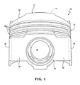
ピストン10の本体部分は、上壁12を提供する上頭部または頂部セクションを有する。上壁12は、内燃機関のシリンダボア内の燃焼ガスに直接曝される上部燃焼表面14を有する。例示の実施形態では、上部燃焼表面14は、中心軸Aの周りに、燃焼ボウル、または非平面の、凹状の、もしくは波状の表面を形成する。頂部ランド18と、続く複数のリング溝20とを提供するリングベルト16は、上壁12から垂下し、中心軸Aの周りに周方向に、かつピストン10の外径に沿って延在する。図1の例示の実施形態では、湾曲したプロファイルを有する少なくとも1つのバルブポケット22がピストン10の上壁12に形成される。
The body portion of the
図に示されるように、ピストン10は、概ね上壁12からリングベルト16の内側に垂下し、横方向に離間される一対のピンボア26を提供する、一対のピンボス24をさらに含む。ピンボア26は、ピンボア軸Bを取り囲む。ピストン10は、リングベルト16から垂下し、互いに直径方向に対向して位置する一対のスカートパネル28も含む。スカートパネル28は、ストラット30によってピンボス24に連結される。
As shown, the
ピストン10は、また、上部燃焼表面14の正反対かつリングベルト16の径方向内側に、上壁12の下側に形成される下方クラウン表面32を含む。下方クラウン表面32は、好ましくは燃焼ボウルから最小距離に位置し、実質的に燃焼ボウルから正反対側の表面である。下方クラウン表面32は、ここで、ピストン10を底部からまっすぐ観察したときにピンボア26を除いて見える表面として規定される。下方クラウン表面32は、上部燃焼表面14の燃焼ボウルに対して概ねぴったり合っている。下方クラウン表面32は、また、ピストン10の下側から見ると開かれて露出しており、囲まれたもしくは部分的に囲まれた冷却空洞、またはオイルもしくは冷却流体を下方クラウン表面32付近に留めやすい任意の他の構成によって画定されていない。
The
ピストン10の下方クラウン表面32は、閉じられたまたは部分的に閉じられた冷却空洞を有する比較対象のピストンよりも、より大きな総表面エリア(表面の外形に従う3次元エリア)およびより大きな投影された表面エリア(平面図で示されるような、2次元エリア、平面)を有する。ピストン10の下側に沿ったこの開口領域は、下方クラウン表面32の真上へクランク室内から飛散するまたはスプレーされるオイルに対し直接のアクセスを提供し、これにより下方クラウン表面32全体がクランク室内からのオイルによって直接吹きかけられることを可能にするとともに、オイルがリストピン(図示せず)の周りに自由に飛散することも可能にし、さらに、ピストン10の重量を大幅に低減させる。したがって、空洞なしのピストン10の概ね開かれた構成は、典型的な閉じられたまたは部分的に閉じられた冷却空洞を有しないが、下方クラウン表面32の最適な冷却およびピンボア26内のリストピン接合に対する潤滑を可能にすると同時に、ある体積のオイルが表面上に残留する時間である燃焼ボウル付近の表面上のオイル残留時間を低減する。低減された残留時間は、閉じられたまたは実質的に閉じられた冷却空洞を有するピストンにおいて起こり得るような、コークス化されたオイルの望ましくない蓄積を低減し得る。このように、ピストン10は、延長された使用にわたって「きれい」であり続け、これによりそれが実質的に蓄積しないままであることを可能にする。
The
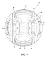
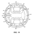
例示の実施形態のピストン10の下方クラウン表面32は、図2および図10に最もよく示される、内側下方クラウン領域34および外側ポケット36を含む、ピストン10のいくつかの領域によって提供される。中心軸Aに位置する下方クラウン表面32の第1部分は、内側下方クラウン領域34によって提供される。内側下方クラウン領域34は、ピンボス24、スカートパネル28、およびストラット30に取り囲まれる。内側下方クラウン領域34によって提供される下方クラウン表面32の2次元および3次元の表面エリアは、典型的には、露出面に対してクランク室から上方向に飛散するまたはスプレーされるオイルによって生じる冷却が強化され得るように最大化され、これによりピストン10の優れた冷却を与える。例示の実施形態では、内側下方クラウン領域34に位置する下方クラウン表面32は、底部から見たときに凹状であるため、オイルがピストン10の片側からピストン10の反対側までのピストン10の往復の間に流され得、これによりピストン10の冷却をさらに強化するようにはたらく。
The
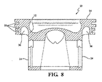
下方クラウン表面32の第2領域は、ピンボス24の外側に位置する外側ポケット36によって提供される。各外側ポケット36は、ピンボス24のうちの1つ、リングベルト16の一部、および1つのピンボス24をスカートパネル28に連結するストラット30に取り囲まれる。外側ポケット36は、底部、クランク軸の側部、および下方クラウン表面32の方向における頭部から、リングベルト16の内面まで延在する中空部を含む。図8〜図10の例示の実施形態では、外側ポケット36は、中心軸Aの方向において、リングベルト16の高さの少なくとも50%にわたって広がる。好都合なことに、外側ポケット36はピストン10の重量を省く。
A second region of the
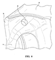
冷却オイルが、典型的にはオイルジェットが冷却オイルをスプレーする内側下方クラウン領域34から外側ポケット36まで通過することを可能にするために、少なくとも1つの穴38、好ましくは複数の穴38が、内側下方クラウン領域34から外側ポケット36まで、ピンボス24および/またはストラット30を通って延在する。図3〜図6、図9および図10は、ピンボス24および/またはストラット30を通って外側ポケット36まで延在する穴38の例を示す。穴38を介して外側ポケット36に提供される冷却オイルの供給は、外側ポケット36の冷却を向上し、ひいてはピストン10の全体の温度を低減する。穴38の存在によって、典型的な冷却チャネルは必要とされない。典型的には、冷却オイルは、リストピンに隣接するエリアにおいてピストン10の底部で注入され、穴38を通って外側ポケット36まで向けられ、通過して大きなエリアにわたって所望の冷却を達成する。
In order to allow the cooling oil to pass from the inner
穴38は、内側下方クラウン領域34から外側ポケット36までの接続を提供するために、下方クラウン表面32、ピンボス24、および/またはストラット30に沿って様々な異なる位置に配置され得る。例示の実施形態では、穴38は、たとえば下方クラウン表面32に隣接して、ピストン10の頂部付近またはより高くに位置する。図1〜図7に示される実施形態では、2つの穴38が内側下方クラウン領域34と外側ポケット36のうちの第1のものとの間に位置し、2つの穴38が内側下方クラウン領域34と外側ポケット36の第2のものとの間に位置する。図3に最もよく示されるように、各穴38は、第1開口部40から第2開口部42まで延在する。第1開口部40は、スカートパネル28とピンボス24との間の、ストラット30のうちの1つに隣接する内側下方クラウン領域34に位置する。第2開口部42は、ストラット30に隣接する、ピンボス24の側部の外側ポケット36に位置する。あるクランク角度でオイルジェットからスプレーする冷却オイルが第1開口部40の中へかつ穴38を通って外側ポケット36へ向けられるように、穴38は、ピストン10の中心軸Aに対しておよびピンボア軸Bに対してある角度で配置され得る。穴38の各々の角度は、特定のエンジン設計、オイルジェットの位置、およびクランク角度に依拠する。1つの実施形態によれば、穴38は、内側下方クラウン領域34から外側ポケット36まで上方向に傾けられる。
The
図8〜図10の例示の実施形態では、ピストン10の下側からスプレーされる冷却オイルが外側ポケット36にアクセスすることを可能にするために、2つの穴38は、ピンボア26の両側の各ピンボス24に、かつリングベルト16を画定する上部エリアに位置する。代替的には、隣接するピンボス24の両側の各ストラット30に、1つの穴38が位置してもよい。穴38は、冷却オイルの良好な流れを可能にするために、外側ポケット36の方向に延在する。この実施形態のピストン10は、実質的に接線の態様で全体的に延在する、計4つの穴を含む。図10では、2つの左の穴38は、本質的に、スカートパネル28に向かって周方向に延在するそれぞれの外側ポケット36の範囲にある。
In the exemplary embodiment of FIGS. 8-10, two
穴38は、様々な異なる形状および大きさを備えてもよい。例示の実施形態では、穴38は、円筒形であり、5mm〜10mmの範囲にある直径を有する。しかしながら、穴38の直径は、4mmほど小さく、設計が許す限り大きくてもよい。図7は、内側下方クラウン領域34と外側ポケット36とを接続するためのピンボス24に隣接するストラット30に形成されるより大きな穴38を有する別の例示の実施形態に係るピストン10を示す。
The
穴38は、様々な異なる方法によって形成され得る。1つの実施形態では、穴38は、ピストンの一体の本体の中へ鋳造または鍛造される。別の実施形態では、穴38は、一体の本体が形成された後に、内側下方クラウン領域34と外側ポケット36との間にあけられる。
The
図8〜図10の実施形態によれば、ピストン10は、冷却オイルを向けるために、内側下方クラウン領域34に配置される少なくとも1つのデフレクタ44を含む。デフレクタ44は、スカートパネル28のうちの1つの内面に沿っておよび/または下方クラウン表面32に沿って位置し得る。デフレクタ44は、1つ以上の凹部46および/または1つ以上のリブ48を含むように設計されてもよい。例示の実施形態では、デフレクタは、たとえば一対の凹部46間に配置される少なくとも1つのリブ48、またはより特定的には、一対の凹部48間に配置される2つのリブ48などのリブ形状の隆起を含む。加えて、別の凹部46がリブ48に対向して下方クラウン表面32に沿って位置してもよい。図10に示される例示の実施形態では、ピストン10の右側に位置する単一の凹部46の長さは、ピストン10の左側のリブ48と凹部46との長さにほぼ等しい。冷却オイルが凹部46の中へスプレーされる場合、オイルは適切な方向に集められ向けられ得る。1つの実施形態によれば、穴38の方向に冷却オイルを向けるために、各凹部46は細長く、大部分においてピストン10の周方向に延在する。代替的に、または追加的に、凹部46のうちの1つが、図10に示されるように、大部分において2つの隆起されたリブ48間に径方向に延在してもよく、冷却オイルビームスプリッタとしてはたらくため、冷却オイルはピンボス24間で中心軸Aへ向かって、少なくともある範囲へ向けられる。また、リブ48は、スプレーされた冷媒の一部を1つより多い方向に向けるための冷却オイルビームスプリッタとしてはたらき得る。図10の例示の実施形態では、一対のリブ48がスカートパネル28のうちの1つに沿ってピンボス24間の中心点に、位置し、リブ48は、ピンボス24に平行に延在して冷却オイルをピンボス24間に下方クラウン表面32の中心軸Aに向かって向ける。この実施形態では、1つの凹部46がリブ48間に位置し、2つの他の凹部46がストラット30に隣接してリブ48の両側に位置する。より特定的には、図10のこの実施形態では、デフレクタ44は左の穴38を通って、かつ外側ポケット36のうちの1つまたは両方の中へ、かつピンボス24間のピストン10の中心軸Aに向かって、冷却オイルを向ける。この場合、好都合なことに冷却オイルはある角度でスプレーされ得るため、ピストン20が下死点にあるとき、冷却オイルは1つの凹部46に向けられるであろう。ピストン20が下死点から上死点に上がるにつれて、冷却オイルの標的位置は、2つのリブ48に対向する第2の凹部46に向かって、ピストン10にわたって移るであろう。プロセスにおいて、スプレーされたオイルのビームは、2つのリブ48を横切り、上記に概説された効果を示すであろう。最終的には、ピストン10が上死点に達したとき、冷却オイルは2つのリブ48に対向する凹部46に向けられるであろう。
According to the embodiment of FIGS. 8-10, the
代替的には、凹部46が2つのリブ48の代わりに設けられてもよく、または凹部46が2つのリブ48間のみに設けられてもよい。各凹部46は好ましくはストラット30のうちの1つを画定するため、凹部46は、好都合なことに、凹部46にアクセスする冷却オイルがピンボス24またはストラット30における少なくとも1つの穴38の方向に、したがって外側ポケット36の中へ流れるであろうことを保証し得る。少なくとも1つのデフレクタ44を用いるとき、ピストン10をピストンの中心軸Aに対して斜めの角度で冷却オイルをスプレーする冷媒ノズル(図示せず)と結合することが好ましい。これにより、ピストン10の位置に応じて、ピストン10の異なるエリアがそのストロークに沿って冷却されることができる。
Alternatively, the
本発明の別の局面は、内燃機関における使用のための空洞なしのピストン10を製造する方法を提供する。典型的には鋼鉄またはアルミニウムで形成されるピストン10の本体部分は、鍛造または鋳造などの様々な異なる方法に従って製造され得る。空洞なしのピストン10の本体部分は、様々な異なる設計も備えてもよく、設計の例示は図1〜図6に示される。
Another aspect of the present invention provides a method of manufacturing a
当該方法は、内側下方クラウン領域34から外側ポケット36まで延在するピストン10の穴38を提供することをさらに含む。このステップは、一体の本体を鋳造もしくは鍛造するプロセスの間に穴38を鋳造すること、または一体の本体を提供した後に穴38をあけることなどの他の好適な加工を含んでもよい。穴38は、典型的には、ピンボス24および/またはストラット30を通って延在する。穴38は、下方クラウン表面32の小さな部分を通って延在してもよい。デフレクタ44は、鋳造もしくは鍛造プロセスの間、または好適な加工を通じて形成されてもよい。
The method further includes providing a
本発明の多くの修正および変形が、上記の教示に照らせば可能であり、以下の請求項の範囲内で特定的に記載された以外の方法で実施され得る。すべての請求項のおよびすべての実施形態のすべての構成は、そのような組み合わせが互いに矛盾しない限り、互いに組み合わせられることができることが理解される。 Many modifications and variations of the present invention are possible in light of the above teachings and may be practiced otherwise than as specifically described within the scope of the following claims. It is understood that all configurations of all claims and all embodiments can be combined with each other as long as such combinations are not inconsistent with each other.
Claims (21)
前記ピストンの下側から露出する下方クラウン表面を含む上壁と、
前記上壁から垂下し、前記ピストンの中心軸の周りに周方向に延在するリングベルトと、
前記上壁から垂下する一対のピンボスと、
前記リングベルトから垂下し、ストラットによって前記ピンボスに連結される一対のスカートパネルと、
前記下方クラウン表面に沿って延在し、前記スカートパネルおよび前記ストラットおよび前記ピンボスに取り囲まれる内側下方クラウン領域と、
前記下方クラウン表面に沿って延在する一対の外側ポケットとを備え、
各外側ポケットは、前記ピンボスのうちの1つ、前記リングベルトの一部、および1つの前記ピンボスを前記スカートパネルに連結する前記ストラットに取り囲まれ、
少なくとも1つの穴が、前記内側下方クラウン領域から前記外側ポケットのうちの1つまで、前記ピンボスのうちの少なくとも1つおよび/または前記ストラットのうちの少なくとも1つを通って延在する、ピストン。 A piston,
An upper wall including a lower crown surface exposed from the underside of the piston;
A ring belt depending from the upper wall and extending circumferentially around the central axis of the piston;
A pair of pin bosses depending from the upper wall;
A pair of skirt panels depending from the ring belt and connected to the pin bosses by struts;
An inner lower crown region extending along the lower crown surface and surrounded by the skirt panel and the struts and the pin bosses;
A pair of outer pockets extending along the lower crown surface;
Each outer pocket is surrounded by one of the pin bosses, a portion of the ring belt, and the strut connecting one pin boss to the skirt panel;
A piston, wherein at least one hole extends from the inner lower crown region to one of the outer pockets through at least one of the pin bosses and / or at least one of the struts.
前記本体の前記材料は、鋼鉄またはアルミニウム系であり、
前記本体は、冷却空洞床、または冷却空洞を画定するもしくは部分的に画定する他の構成を有さず、
前記本体は、上部燃焼表面を提示する前記上壁を含み、
前記上部燃焼表面は、前記中心軸の周りの非平面の表面であり、
前記リングベルトは、頂部ランドと、前記中心軸の周りに周方向にかつ前記ピストンの外径に沿って延在する複数のリング溝とを含み、
前記ピンボスは、前記リングベルトの内側に配置され、ピンボア軸を取り囲む横方向に離間される一対のピンボアを提供し、
前記一対のスカートパネルは、互いに直径方向に対向して位置し、
前記下方クラウン表面は、前記リングベルトの径方向内側に配置され、
前記下方クラウン表面は、囲まれたもしくは部分的に囲まれた冷却空洞、または流体を留めやすい他の構成によって画定されておらず、
前記下方クラウン表面の第1部分が前記内側下方クラウン領域によって提供され、前記下方クラウン表面の第2部分が前記外側ポケットによって提供され、
前記内側下方クラウン領域は、前記中心軸に位置し、前記ピンボスおよび前記スカートパネルおよび前記ストラットに取り囲まれ、
前記内側下方クラウン領域に位置する前記下方クラウン表面は、前記ピストンの底部から見たときに凹状であり、
前記外側ポケットは、前記ピンボスの外側に位置し、
複数の前記穴は、前記内側下方クラウン領域から前記外側ポケットまで、前記ピンボスおよび/または前記ストラットを通って延在し、
前記穴は、前記下方クラウン表面に隣接して位置し、
各穴は、第1開口部から第2開口部まで延在し、
前記第1開口部は、前記内側下方クラウン領域に位置し、前記第2開口部は、前記外側ポケットのうちの隣接するものに位置し、
前記穴は、前記ピストンの前記中心軸および前記ピンボア軸に対してある角度で配置され、
前記穴は、円筒形の形状であり、5mm〜10mmの範囲にある直径を有する、請求項1に記載のピストン。 Including a body formed of a single piece of material;
The material of the body is steel or aluminum;
The body does not have a cooling cavity floor or other configuration that defines or partially defines the cooling cavity;
The body includes the upper wall presenting an upper combustion surface;
The upper combustion surface is a non-planar surface around the central axis;
The ring belt includes a top land and a plurality of ring grooves extending circumferentially around the central axis and along the outer diameter of the piston;
The pin bosses are disposed inside the ring belt and provide a pair of pin bores spaced laterally surrounding a pin bore axis;
The pair of skirt panels are diametrically opposed to each other,
The lower crown surface is disposed radially inward of the ring belt;
The lower crown surface is not defined by an enclosed or partially enclosed cooling cavity, or other configuration that tends to retain fluid;
A first portion of the lower crown surface is provided by the inner lower crown region, and a second portion of the lower crown surface is provided by the outer pocket;
The inner lower crown region is located on the central axis and is surrounded by the pin boss and the skirt panel and the strut;
The lower crown surface located in the inner lower crown region is concave when viewed from the bottom of the piston;
The outer pocket is located outside the pin boss,
A plurality of the holes extending from the inner lower crown region to the outer pocket through the pin bosses and / or the struts;
The hole is located adjacent to the lower crown surface;
Each hole extends from the first opening to the second opening,
The first opening is located in the inner lower crown region, and the second opening is located in an adjacent one of the outer pockets;
The hole is disposed at an angle with respect to the central axis of the piston and the pin bore axis;
The piston of claim 1, wherein the hole is cylindrical in shape and has a diameter in the range of 5 mm to 10 mm.
上壁を含む本体を提供するステップを含み、前記上壁は、前記ピストンの下側から露出する下方クラウン表面を含み、リングベルトが前記上壁から垂下し、前記ピストンの中心軸の周りに周方向に延在し、一対のピンボスが前記上壁から垂下し、一対のスカートパネルが前記リングベルトから垂下し、ストラットによって前記ピンボスに連結され、内側下方クラウン領域が前記下方クラウン表面に沿って延在し、前記スカートパネルおよび前記ストラットおよび前記ピンボスに取り囲まれ、一対の外側ポケットが前記下方クラウン表面に沿って延在し、各外側ポケットは、前記ピンボスのうちの1つおよび前記リングベルトの一部および1つの前記ピンボスを前記スカートパネルに連結する前記ストラットに取り囲まれ、前記方法はさらに、
前記内側下方クラウン領域から前記外側ポケットのうちの1つまで、前記ピンボスのうちの少なくとも1つおよび/または前記ストラットのうちの少なくとも1つを通る少なくとも1つの穴を形成するステップを備える、方法。 A method of manufacturing a piston, comprising:
Providing a body including an upper wall, the upper wall including a lower crown surface exposed from the underside of the piston, and a ring belt depending from the upper wall and surrounding about the central axis of the piston. A pair of pin bosses depending from the upper wall, a pair of skirt panels depending from the ring belt, connected to the pin bosses by struts, and an inner lower crown region extending along the lower crown surface. Surrounded by the skirt panel and the struts and the pin bosses, and a pair of outer pockets extending along the lower crown surface, each outer pocket being one of the pin bosses and one of the ring belts. Surrounded by the strut connecting a portion and one pin boss to the skirt panel, the method further comprising:
Forming at least one hole through at least one of the pin bosses and / or at least one of the struts from the inner lower crown region to one of the outer pockets.
Applications Claiming Priority (7)
| Application Number | Priority Date | Filing Date | Title |
|---|---|---|---|
| US201662298952P | 2016-02-23 | 2016-02-23 | |
| US62/298,952 | 2016-02-23 | ||
| DE102016204830.9 | 2016-03-23 | ||
| DE102016204830.9A DE102016204830A1 (en) | 2016-03-23 | 2016-03-23 | Piston for an internal combustion engine |
| US15/437,631 | 2017-02-21 | ||
| US15/437,631 US10428761B2 (en) | 2016-02-23 | 2017-02-21 | Galleryless piston with improved pocket cooling |
| PCT/US2017/018777 WO2017147097A1 (en) | 2016-02-23 | 2017-02-22 | Galleryless piston with improved pocket cooling |
Publications (2)
| Publication Number | Publication Date |
|---|---|
| JP2019506567A true JP2019506567A (en) | 2019-03-07 |
| JP2019506567A5 JP2019506567A5 (en) | 2020-04-02 |
Family
ID=59629739
Family Applications (1)
| Application Number | Title | Priority Date | Filing Date |
|---|---|---|---|
| JP2018544334A Withdrawn JP2019506567A (en) | 2016-02-23 | 2017-02-22 | Cavityless piston with improved pocket cooling |
Country Status (8)
| Country | Link |
|---|---|
| US (1) | US10428761B2 (en) |
| EP (1) | EP3420216A1 (en) |
| JP (1) | JP2019506567A (en) |
| KR (1) | KR20180112054A (en) |
| CN (1) | CN109154252A (en) |
| BR (1) | BR112018017109A2 (en) |
| DE (1) | DE102016204830A1 (en) |
| WO (1) | WO2017147097A1 (en) |
Cited By (1)
| Publication number | Priority date | Publication date | Assignee | Title |
|---|---|---|---|---|
| US20230417203A1 (en) * | 2022-06-28 | 2023-12-28 | GM Global Technology Operations LLC | Piston for use in internal combustion engines and method of making the piston |
Families Citing this family (5)
| Publication number | Priority date | Publication date | Assignee | Title |
|---|---|---|---|---|
| US10352270B2 (en) * | 2016-03-01 | 2019-07-16 | Tenneco Inc. | Galleryless piston with connection to pockets |
| MX2018013353A (en) * | 2016-05-04 | 2019-02-20 | Ks Kolbenschmidt Gmbh | Piston. |
| USD897373S1 (en) * | 2018-09-22 | 2020-09-29 | Chaoming Li | Piston |
| CN111174273B (en) * | 2020-01-17 | 2021-05-18 | 宁波方太厨具有限公司 | Expansion tank and dual-purpose furnace using same |
| USD1009938S1 (en) * | 2022-05-24 | 2024-01-02 | Reme, Llc | Elliptical piston for a rotary steerable tool |
Family Cites Families (26)
| Publication number | Priority date | Publication date | Assignee | Title |
|---|---|---|---|---|
| US1327147A (en) | 1916-05-11 | 1920-01-06 | Packard Motor Car Co | Hydrocarbon-motor |
| US2046196A (en) * | 1935-01-19 | 1936-06-30 | Gen Motors Corp | Piston |
| DE1191176B (en) | 1962-09-08 | 1965-04-15 | Mahle Kg | Pistons for internal combustion engines |
| DE3814500A1 (en) | 1988-04-29 | 1989-11-09 | Mahle Gmbh | Piston, especially for internal combustion engines |
| JPH0327856U (en) | 1989-07-28 | 1991-03-20 | ||
| JPH09329056A (en) | 1996-06-11 | 1997-12-22 | Toyota Motor Corp | Internal combustion engine piston |
| US5860395A (en) | 1997-09-04 | 1999-01-19 | Chrysler Corporation | Piston cooling by oil flow from a pocket reservoir and passageway formed in the piston |
| WO2001027441A1 (en) * | 1999-10-08 | 2001-04-19 | Federal-Mogul Corporation | Dual gallery piston |
| DE10106435A1 (en) * | 2001-02-13 | 2002-08-14 | Bayerische Motoren Werke Ag | Pistons, in particular for an internal combustion engine |
| DE10301367A1 (en) | 2003-01-16 | 2004-07-29 | Mahle Gmbh | Method for making shaker bores in the cooling channel of a one-piece piston |
| DE10322921A1 (en) | 2003-05-21 | 2004-12-16 | Mahle Gmbh | Method of manufacturing a one-piece piston for an internal combustion engine |
| CN2623891Y (en) * | 2003-05-21 | 2004-07-07 | 中国第一汽车集团公司 | Open type internal cooling oil duct of piston |
| JP2005090448A (en) * | 2003-09-19 | 2005-04-07 | Nissan Diesel Motor Co Ltd | Piston for internal combustion engine |
| JP2006214298A (en) | 2005-02-01 | 2006-08-17 | Hitachi Ltd | Piston of internal combustion engine |
| JP4333693B2 (en) | 2006-05-22 | 2009-09-16 | トヨタ自動車株式会社 | Piston for internal combustion engine and internal combustion engine |
| DE102007058789A1 (en) | 2007-12-06 | 2009-06-10 | Federal-Mogul Nürnberg GmbH | Casting piston with support ribs and method for producing such a piston |
| KR20090126699A (en) * | 2008-06-05 | 2009-12-09 | 현대자동차주식회사 | Piston of engine |
| JP5008627B2 (en) | 2008-09-17 | 2012-08-22 | 本田技研工業株式会社 | Piston and manufacturing method thereof |
| JP4861394B2 (en) | 2008-12-05 | 2012-01-25 | 本田技研工業株式会社 | piston |
| JP5063634B2 (en) * | 2009-03-12 | 2012-10-31 | 日立オートモティブシステムズ株式会社 | Piston of internal combustion engine |
| DE102011012685A1 (en) * | 2011-03-01 | 2012-09-06 | Mahle International Gmbh | Piston for an internal combustion engine |
| EP2898209A1 (en) * | 2012-09-18 | 2015-07-29 | Federal-Mogul Corporation | Steel piston with counter-bore design |
| KR101383121B1 (en) * | 2013-07-01 | 2014-04-09 | 삼영기계주식회사 | A piston assembly |
| CN105940213B (en) | 2013-11-07 | 2019-11-26 | 天纳克股份有限公司 | Monoblock type is without passage piston and its building method |
| CN107110063B (en) * | 2014-10-30 | 2019-10-22 | 天纳克公司 | Piston |
| US20160169153A1 (en) * | 2014-12-11 | 2016-06-16 | Caterpillar Inc. | Engine Piston |
-
2016
- 2016-03-23 DE DE102016204830.9A patent/DE102016204830A1/en not_active Ceased
-
2017
- 2017-02-21 US US15/437,631 patent/US10428761B2/en not_active Expired - Fee Related
- 2017-02-22 KR KR1020187027310A patent/KR20180112054A/en unknown
- 2017-02-22 BR BR112018017109A patent/BR112018017109A2/en not_active IP Right Cessation
- 2017-02-22 WO PCT/US2017/018777 patent/WO2017147097A1/en active Application Filing
- 2017-02-22 EP EP17709845.6A patent/EP3420216A1/en not_active Withdrawn
- 2017-02-22 CN CN201780022798.1A patent/CN109154252A/en active Pending
- 2017-02-22 JP JP2018544334A patent/JP2019506567A/en not_active Withdrawn
Cited By (1)
| Publication number | Priority date | Publication date | Assignee | Title |
|---|---|---|---|---|
| US20230417203A1 (en) * | 2022-06-28 | 2023-12-28 | GM Global Technology Operations LLC | Piston for use in internal combustion engines and method of making the piston |
Also Published As
| Publication number | Publication date |
|---|---|
| US20170241374A1 (en) | 2017-08-24 |
| WO2017147097A1 (en) | 2017-08-31 |
| DE102016204830A1 (en) | 2017-09-28 |
| BR112018017109A2 (en) | 2019-01-15 |
| EP3420216A1 (en) | 2019-01-02 |
| CN109154252A (en) | 2019-01-04 |
| WO2017147097A8 (en) | 2018-09-07 |
| KR20180112054A (en) | 2018-10-11 |
| US10428761B2 (en) | 2019-10-01 |
Similar Documents
| Publication | Publication Date | Title |
|---|---|---|
| JP6653704B2 (en) | Double gallery piston with reduced compression height, piston assembly with the same, and method of construction thereof | |
| JP2019506567A (en) | Cavityless piston with improved pocket cooling | |
| US10968862B2 (en) | Monolithic, galleryless piston and method of construction thereof | |
| US10738731B2 (en) | Monolithic, galleryless piston and method of construction thereof | |
| JP2019506567A5 (en) | ||
| JP2019508624A (en) | Cavityless piston with slotted ring groove | |
| US10344706B2 (en) | Galleryless piston with cutout above pin bore | |
| CN109072764B (en) | Piston with asymmetric upper combustion surface and method of making same | |
| JP2019507283A (en) | Hollowless piston with connection to pocket | |
| JP2019509425A (en) | Cavityless piston with oil discharge mechanism | |
| KR102582339B1 (en) | Monolithic piston without gallery, and method of manufacturing the same |
Legal Events
| Date | Code | Title | Description |
|---|---|---|---|
| A711 | Notification of change in applicant |
Free format text: JAPANESE INTERMEDIATE CODE: A712 Effective date: 20181109 |
|
| A521 | Written amendment |
Free format text: JAPANESE INTERMEDIATE CODE: A523 Effective date: 20200218 |
|
| A621 | Written request for application examination |
Free format text: JAPANESE INTERMEDIATE CODE: A621 Effective date: 20200218 |
|
| A761 | Written withdrawal of application |
Free format text: JAPANESE INTERMEDIATE CODE: A761 Effective date: 20200316 |