JP6617840B2 - P-type thermoelectric conversion material, thermoelectric conversion module, and method for producing p-type thermoelectric conversion material - Google Patents
P-type thermoelectric conversion material, thermoelectric conversion module, and method for producing p-type thermoelectric conversion material Download PDFInfo
- Publication number
- JP6617840B2 JP6617840B2 JP2018563259A JP2018563259A JP6617840B2 JP 6617840 B2 JP6617840 B2 JP 6617840B2 JP 2018563259 A JP2018563259 A JP 2018563259A JP 2018563259 A JP2018563259 A JP 2018563259A JP 6617840 B2 JP6617840 B2 JP 6617840B2
- Authority
- JP
- Japan
- Prior art keywords
- thermoelectric conversion
- type thermoelectric
- conversion material
- type
- raw material
- Prior art date
- Legal status (The legal status is an assumption and is not a legal conclusion. Google has not performed a legal analysis and makes no representation as to the accuracy of the status listed.)
- Active
Links
Images


Classifications
-
- H—ELECTRICITY
- H10—SEMICONDUCTOR DEVICES; ELECTRIC SOLID-STATE DEVICES NOT OTHERWISE PROVIDED FOR
- H10N—ELECTRIC SOLID-STATE DEVICES NOT OTHERWISE PROVIDED FOR
- H10N10/00—Thermoelectric devices comprising a junction of dissimilar materials, i.e. devices exhibiting Seebeck or Peltier effects
- H10N10/80—Constructional details
- H10N10/85—Thermoelectric active materials
- H10N10/851—Thermoelectric active materials comprising inorganic compositions
- H10N10/855—Thermoelectric active materials comprising inorganic compositions comprising compounds containing boron, carbon, oxygen or nitrogen
-
- B—PERFORMING OPERATIONS; TRANSPORTING
- B22—CASTING; POWDER METALLURGY
- B22F—WORKING METALLIC POWDER; MANUFACTURE OF ARTICLES FROM METALLIC POWDER; MAKING METALLIC POWDER; APPARATUS OR DEVICES SPECIALLY ADAPTED FOR METALLIC POWDER
- B22F9/00—Making metallic powder or suspensions thereof
- B22F9/02—Making metallic powder or suspensions thereof using physical processes
- B22F9/04—Making metallic powder or suspensions thereof using physical processes starting from solid material, e.g. by crushing, grinding or milling
-
- C—CHEMISTRY; METALLURGY
- C22—METALLURGY; FERROUS OR NON-FERROUS ALLOYS; TREATMENT OF ALLOYS OR NON-FERROUS METALS
- C22C—ALLOYS
- C22C30/00—Alloys containing less than 50% by weight of each constituent
-
- C—CHEMISTRY; METALLURGY
- C22—METALLURGY; FERROUS OR NON-FERROUS ALLOYS; TREATMENT OF ALLOYS OR NON-FERROUS METALS
- C22C—ALLOYS
- C22C30/00—Alloys containing less than 50% by weight of each constituent
- C22C30/04—Alloys containing less than 50% by weight of each constituent containing tin or lead
-
- C—CHEMISTRY; METALLURGY
- C22—METALLURGY; FERROUS OR NON-FERROUS ALLOYS; TREATMENT OF ALLOYS OR NON-FERROUS METALS
- C22C—ALLOYS
- C22C33/00—Making ferrous alloys
- C22C33/02—Making ferrous alloys by powder metallurgy
-
- C—CHEMISTRY; METALLURGY
- C22—METALLURGY; FERROUS OR NON-FERROUS ALLOYS; TREATMENT OF ALLOYS OR NON-FERROUS METALS
- C22C—ALLOYS
- C22C33/00—Making ferrous alloys
- C22C33/02—Making ferrous alloys by powder metallurgy
- C22C33/0257—Making ferrous alloys by powder metallurgy characterised by the range of the alloying elements
- C22C33/0278—Making ferrous alloys by powder metallurgy characterised by the range of the alloying elements with at least one alloying element having a minimum content above 5%
-
- C—CHEMISTRY; METALLURGY
- C22—METALLURGY; FERROUS OR NON-FERROUS ALLOYS; TREATMENT OF ALLOYS OR NON-FERROUS METALS
- C22C—ALLOYS
- C22C38/00—Ferrous alloys, e.g. steel alloys
- C22C38/02—Ferrous alloys, e.g. steel alloys containing silicon
-
- C—CHEMISTRY; METALLURGY
- C22—METALLURGY; FERROUS OR NON-FERROUS ALLOYS; TREATMENT OF ALLOYS OR NON-FERROUS METALS
- C22C—ALLOYS
- C22C38/00—Ferrous alloys, e.g. steel alloys
- C22C38/06—Ferrous alloys, e.g. steel alloys containing aluminium
-
- C—CHEMISTRY; METALLURGY
- C22—METALLURGY; FERROUS OR NON-FERROUS ALLOYS; TREATMENT OF ALLOYS OR NON-FERROUS METALS
- C22C—ALLOYS
- C22C38/00—Ferrous alloys, e.g. steel alloys
- C22C38/14—Ferrous alloys, e.g. steel alloys containing titanium or zirconium
-
- H—ELECTRICITY
- H02—GENERATION; CONVERSION OR DISTRIBUTION OF ELECTRIC POWER
- H02N—ELECTRIC MACHINES NOT OTHERWISE PROVIDED FOR
- H02N11/00—Generators or motors not provided for elsewhere; Alleged perpetua mobilia obtained by electric or magnetic means
-
- H—ELECTRICITY
- H10—SEMICONDUCTOR DEVICES; ELECTRIC SOLID-STATE DEVICES NOT OTHERWISE PROVIDED FOR
- H10N—ELECTRIC SOLID-STATE DEVICES NOT OTHERWISE PROVIDED FOR
- H10N10/00—Thermoelectric devices comprising a junction of dissimilar materials, i.e. devices exhibiting Seebeck or Peltier effects
- H10N10/10—Thermoelectric devices comprising a junction of dissimilar materials, i.e. devices exhibiting Seebeck or Peltier effects operating with only the Peltier or Seebeck effects
- H10N10/17—Thermoelectric devices comprising a junction of dissimilar materials, i.e. devices exhibiting Seebeck or Peltier effects operating with only the Peltier or Seebeck effects characterised by the structure or configuration of the cell or thermocouple forming the device
-
- H—ELECTRICITY
- H10—SEMICONDUCTOR DEVICES; ELECTRIC SOLID-STATE DEVICES NOT OTHERWISE PROVIDED FOR
- H10N—ELECTRIC SOLID-STATE DEVICES NOT OTHERWISE PROVIDED FOR
- H10N10/00—Thermoelectric devices comprising a junction of dissimilar materials, i.e. devices exhibiting Seebeck or Peltier effects
- H10N10/80—Constructional details
- H10N10/85—Thermoelectric active materials
- H10N10/851—Thermoelectric active materials comprising inorganic compositions
- H10N10/854—Thermoelectric active materials comprising inorganic compositions comprising only metals
-
- B—PERFORMING OPERATIONS; TRANSPORTING
- B22—CASTING; POWDER METALLURGY
- B22F—WORKING METALLIC POWDER; MANUFACTURE OF ARTICLES FROM METALLIC POWDER; MAKING METALLIC POWDER; APPARATUS OR DEVICES SPECIALLY ADAPTED FOR METALLIC POWDER
- B22F9/00—Making metallic powder or suspensions thereof
- B22F9/02—Making metallic powder or suspensions thereof using physical processes
- B22F9/04—Making metallic powder or suspensions thereof using physical processes starting from solid material, e.g. by crushing, grinding or milling
- B22F2009/041—Making metallic powder or suspensions thereof using physical processes starting from solid material, e.g. by crushing, grinding or milling by mechanical alloying, e.g. blending, milling
-
- B—PERFORMING OPERATIONS; TRANSPORTING
- B22—CASTING; POWDER METALLURGY
- B22F—WORKING METALLIC POWDER; MANUFACTURE OF ARTICLES FROM METALLIC POWDER; MAKING METALLIC POWDER; APPARATUS OR DEVICES SPECIALLY ADAPTED FOR METALLIC POWDER
- B22F2301/00—Metallic composition of the powder or its coating
- B22F2301/35—Iron
-
- B—PERFORMING OPERATIONS; TRANSPORTING
- B22—CASTING; POWDER METALLURGY
- B22F—WORKING METALLIC POWDER; MANUFACTURE OF ARTICLES FROM METALLIC POWDER; MAKING METALLIC POWDER; APPARATUS OR DEVICES SPECIALLY ADAPTED FOR METALLIC POWDER
- B22F2998/00—Supplementary information concerning processes or compositions relating to powder metallurgy
- B22F2998/10—Processes characterised by the sequence of their steps
-
- B—PERFORMING OPERATIONS; TRANSPORTING
- B22—CASTING; POWDER METALLURGY
- B22F—WORKING METALLIC POWDER; MANUFACTURE OF ARTICLES FROM METALLIC POWDER; MAKING METALLIC POWDER; APPARATUS OR DEVICES SPECIALLY ADAPTED FOR METALLIC POWDER
- B22F2999/00—Aspects linked to processes or compositions used in powder metallurgy
-
- C—CHEMISTRY; METALLURGY
- C22—METALLURGY; FERROUS OR NON-FERROUS ALLOYS; TREATMENT OF ALLOYS OR NON-FERROUS METALS
- C22C—ALLOYS
- C22C2200/00—Crystalline structure
- C22C2200/02—Amorphous
Description
本発明は、p型熱電変換材料、熱電変換モジュール及びp型熱電変換材料の製造方法に関する。 The present invention relates to a p-type thermoelectric conversion material, a thermoelectric conversion module, and a method for producing a p-type thermoelectric conversion material.
排熱エネルギーを電力に変換する技術として、熱電変換モジュールが知られており、300℃以下の温度域での排熱回収に適応可能な熱電変換材料の代表的なものとして、Fe2VAl系フルホイスラー合金やBi−Te系半導体が挙げられる。中でもFe2VAl系フルホイスラー合金は、Bi−Te系半導体と比較して、毒性が低く環境負荷の小さい材料として知られている。A thermoelectric conversion module is known as a technology for converting exhaust heat energy into electric power. As a representative thermoelectric conversion material applicable to exhaust heat recovery in a temperature range of 300 ° C. or lower, Fe 2 VAl-based full Examples include Heusler alloys and Bi-Te based semiconductors. Among them, the Fe 2 VAl-based full Heusler alloy is known as a material having a low toxicity and a low environmental load as compared with a Bi—Te-based semiconductor.
一般に、熱電変換モジュールは、n型の熱電変換材料とp型の熱電変換材料とが組み合わされて使用される。このため、熱電変換モジュールにおいて高い熱電変換特性を得るためには、n型とp型の双方において、高い性能指数ZTを得ることが求められる。現状では、p型の熱電変換材料の性能指数ZTは、n型と比較して低いため、その値の向上が求められている。 Generally, a thermoelectric conversion module is used by combining an n-type thermoelectric conversion material and a p-type thermoelectric conversion material. For this reason, in order to obtain high thermoelectric conversion characteristics in the thermoelectric conversion module, it is required to obtain a high figure of merit ZT for both n-type and p-type. At present, since the figure of merit ZT of the p-type thermoelectric conversion material is lower than that of the n-type, improvement of the value is required.
非特許文献1では、フルホイスラー合金をp型の熱電変換材料として適用したときの性能指数ZTとして、これまでで最も高い値である性能指数ZT=0.13を示すFe2VAl系フルホイスラー合金が開示されている。In Non-Patent Document 1, as a figure of merit ZT when a full Heusler alloy is applied as a p-type thermoelectric conversion material, an Fe 2 VAl-based full Heusler alloy showing a figure of merit ZT = 0.13 which is the highest value so far. Is disclosed.
特許文献1では、毒性が低く、かつV、Bi、Te等の高コストな元素を含む材料を用いることなく作製でき、高い性能指数ZTを得られる熱電変換材料として、Fe2TiSi系フルホイスラー合金が提案されている。In Patent Document 1, an Fe 2 TiSi-based full-Heusler alloy is used as a thermoelectric conversion material that has a low toxicity and can be produced without using a material containing a high-cost element such as V, Bi, or Te, and can obtain a high figure of merit ZT. Has been proposed.
非特許文献1に記載されたFe2VAl系フルホイスラー合金は、上記したように、従来のp型のフルホイスラー合金と比較すると高い性能指数ZTを示すものの、n型の熱電変換材料の性能指数ZTと比較すると、その値は半分程度の値に留まっており、必ずしも十分な熱電変換特性を得られるものではなかった。As described above, the Fe 2 VAl-based full-Heusler alloy described in Non-Patent Document 1 shows a high figure of merit ZT compared to the conventional p-type full-Heusler alloy, but the figure of merit of the n-type thermoelectric conversion material Compared with ZT, the value is only about half, and sufficient thermoelectric conversion characteristics are not necessarily obtained.
特許文献1では、Fe:Ti:Si=2:1:1を中心とする組成比を有するFe2TiSi系フルホイスラー合金についての、p型としての熱電変換特性が記載されているが、p型の熱電変換材料には、更なる熱電変換特性の向上が求められている。Patent Document 1 describes p-type thermoelectric conversion characteristics for an Fe 2 TiSi-based full-Heusler alloy having a composition ratio centered on Fe: Ti: Si = 2: 1: 1. These thermoelectric conversion materials are required to further improve thermoelectric conversion characteristics.
そこで、本発明の目的は、高い熱電変換特性を得られるp型熱電変換材料、熱電変換モジュール及びp型熱電変換材料の製造方法を提供することにある。 Accordingly, an object of the present invention is to provide a p-type thermoelectric conversion material, a thermoelectric conversion module, and a method for producing a p-type thermoelectric conversion material that can obtain high thermoelectric conversion characteristics.
本発明に係るp型熱電変換材料の好ましい実施形態としては、下記一般式(1)で表される組成を有するフルホイスラー合金を有し、かつ相対密度が85%以上であることを特徴とする。
FexTiyMAaMBb …(1)
(式(1)中、MAは、Si、Sn及びGeからなる群から選択される1種の元素であり、MBは、Al、Ga及びInからなる群から選択される1種の元素であり、x、y、a、bは、それぞれ原子%でx+y+a+b=100、a+b=z、50<x≦52.5、20≦y≦24.5、24.5≦z≦29、a>0、b>0を満足する数である。)
本発明に係る熱電変換モジュールの好ましい実施形態としては、複数の熱電変換素子と、前記熱電変換素子の間を電気的に接続する電極とを有する熱電変換モジュールであって、前記熱電変換素子として、下記一般式(1)で表される組成を有するフルホイスラー合金を有し、かつ相対密度が85%以上であるp型熱電変換材料を含むp型熱電変換素子と、前記p型熱電変換素子と前記電極により接続されたn型熱電変換素子とを有することを特徴とする。
FexTiyMAaMBb …(1)
(式(1)中、MAは、Si、Sn及びGeからなる群から選択される1種の元素であり、MBは、Al、Ga及びInからなる群から選択される1種の元素であり、x、y、a、bは、それぞれ原子%でx+y+a+b=100、a+b=z、50<x≦52.5、20≦y≦24.5、24.5≦z≦29、a>0、b>0を満足する数である。)
本発明に係るp型熱電変換材料の製造方法の好ましい実施形態としては、Fe原料粉末、Ti原料粉末、MA原料粉末、MB原料粉末を、目的組成に応じた割合で準備し、前記Fe原料粉末、前記Ti原料粉末、前記MA原料粉末及び前記MB原料粉末を混合してFe、Ti、MA、及びMBを含む混合物を調製し、該混合物をアモルファス化してアモルファス化された合金とし、前記アモルファス化された合金を加熱して、下記一般式(1)で表される組成を有するフルホイスラー合金を有し、かつ相対密度が85%以上であるp型熱電変換材料を製造することを特徴とする。
FexTiyMAaMBb …(1)
(式(1)中、MAは、Si、Sn及びGeからなる群から選択される1種の元素であり、MBは、Al、Ga及びInからなる群から選択される1種の元素であり、x、y、a、bは、それぞれ原子%でx+y+a+b=100、a+b=z、50<x≦52.5、20≦y≦24.5、24.5≦z≦29、a>0、b>0を満足する数である。)As a preferred embodiment of the p-type thermoelectric conversion material according to the present invention, the p-type thermoelectric conversion material has a full Heusler alloy having a composition represented by the following general formula (1), and has a relative density of 85% or more. .
Fe x Ti y MA a MB b ... (1)
(In formula (1), MA is one element selected from the group consisting of Si, Sn and Ge, and MB is one element selected from the group consisting of Al, Ga and In. , X, y, a, and b are atomic% x + y + a + b = 100, a + b = z, 50 <x ≦ 52.5, 20 ≦ y ≦ 24.5, 24.5 ≦ z ≦ 29, a> 0, It is a number satisfying b> 0.)
A preferred embodiment of the thermoelectric conversion module according to the present invention is a thermoelectric conversion module having a plurality of thermoelectric conversion elements and electrodes that electrically connect the thermoelectric conversion elements, and as the thermoelectric conversion elements, A p-type thermoelectric conversion element comprising a p-type thermoelectric conversion material having a full Heusler alloy having a composition represented by the following general formula (1) and having a relative density of 85% or more, and the p-type thermoelectric conversion element: And an n-type thermoelectric conversion element connected by the electrode.
Fe x Ti y MA a MB b ... (1)
(In formula (1), MA is one element selected from the group consisting of Si, Sn and Ge, and MB is one element selected from the group consisting of Al, Ga and In. , X, y, a, and b are atomic% x + y + a + b = 100, a + b = z, 50 <x ≦ 52.5, 20 ≦ y ≦ 24.5, 24.5 ≦ z ≦ 29, a> 0, It is a number satisfying b> 0.)
As a preferred embodiment of the method for producing a p-type thermoelectric conversion material according to the present invention, Fe raw material powder, Ti raw material powder, MA raw material powder, MB raw material powder are prepared in proportions according to the target composition, and the Fe raw material powder The Ti raw material powder, the MA raw material powder and the MB raw material powder are mixed to prepare a mixture containing Fe, Ti, MA, and MB. The mixture is amorphized to obtain an amorphous alloy, and The obtained alloy is heated to produce a p-type thermoelectric conversion material having a full Heusler alloy having a composition represented by the following general formula (1) and having a relative density of 85% or more. .
Fe x Ti y MA a MB b ... (1)
(In formula (1), MA is one element selected from the group consisting of Si, Sn and Ge, and MB is one element selected from the group consisting of Al, Ga and In. , X, y, a, and b are atomic% x + y + a + b = 100, a + b = z, 50 <x ≦ 52.5, 20 ≦ y ≦ 24.5, 24.5 ≦ z ≦ 29, a> 0, It is a number satisfying b> 0.)
本発明によれば、高い熱電変換特性を得られるp型熱電変換材料、熱電変換モジュール及びp型熱電変換材料の製造方法を実現することができる。 ADVANTAGE OF THE INVENTION According to this invention, the manufacturing method of the p-type thermoelectric conversion material, thermoelectric conversion module, and p-type thermoelectric conversion material which can obtain a high thermoelectric conversion characteristic is realizable.
実施例に係るp型熱電変換材料は、Fe2TiM系のフルホイスラー合金を有する。ここで、金属Mとは、Fe、Ti以外の金属元素又は半金属元素をいう。本発明者らは、Fe2TiM系フルホイスラー合金のp型の熱電変換特性について検討した結果、従来、p型の熱電変換材料における有用な組成として検討されてきた、Fe:Ti:Si=2:1:1を中心とする組成比率から変更した、下記一般式(1)で表される組成を有するフルホイスラー合金において、高い熱電変換性能を得られることを見出した。The p-type thermoelectric conversion material according to the example has a Fe 2 TiM-based full Heusler alloy. Here, the metal M refers to metal elements or metalloid elements other than Fe and Ti. As a result of examining the p-type thermoelectric conversion characteristics of the Fe 2 TiM-based full-Heusler alloy, the present inventors have conventionally studied Fe: Ti: Si = 2, which has been studied as a useful composition in a p-type thermoelectric conversion material. It has been found that high thermoelectric conversion performance can be obtained in a full Heusler alloy having a composition represented by the following general formula (1), which is changed from a composition ratio centered at 1: 1.
FexTiyMAaMBb …(1)
(式(1)中、MAは、Si、Sn及びGeからなる群から選択される1種の元素であり、MBは、Al、Ga及びInからなる群から選択される1種の元素であり、x、y、a、bは、それぞれ原子%でx+y+a+b=100、a+b=z、50<x≦52.5、20≦y≦24.5、24.5≦z≦29、a>0、b>0を満足する数である。)
熱電変換モジュールの最大出力は、熱電変換材料の無次元の性能指数ZTに依存する。このため、熱電変換材料の性能は、下記式(2)の無次元の性能指数ZTで評価される。 Fe x Ti y MA a MB b ... (1)
(In formula (1), MA is one element selected from the group consisting of Si, Sn, and Ge, and MB is one element selected from the group consisting of Al, Ga, and In. , X, y, a, and b are atomic% x + y + a + b = 100, a + b = z, 50 <x ≦ 52.5, 20 ≦ y ≦ 24.5, 24.5 ≦ z ≦ 29, a> 0, It is a number satisfying b> 0.)
The maximum output of the thermoelectric conversion module depends on the dimensionless figure of merit ZT of the thermoelectric conversion material. For this reason, the performance of the thermoelectric conversion material is evaluated by a dimensionless figure of merit ZT of the following formula (2).

なお、以下では、「無次元の性能指数ZT」を、単に「性能指数ZT」と示す。式(2)において、Sはゼーベック係数であり、ρは電気抵抗率であり、κは熱伝導率であり、Tは温度である。従って、熱電変換モジュールの最大出力Pを向上させるためには、熱電変換材料のゼーベック係数Sを増加させ、電気抵抗率ρを減少させ、熱伝導率κを減少させることが望ましい。 In the following, the “dimensionless figure of merit ZT” is simply referred to as “performance figure of merit ZT”. In equation (2), S is the Seebeck coefficient, ρ is the electrical resistivity, κ is the thermal conductivity, and T is the temperature. Therefore, in order to improve the maximum output P of the thermoelectric conversion module, it is desirable to increase the Seebeck coefficient S of the thermoelectric conversion material, decrease the electrical resistivity ρ, and decrease the thermal conductivity κ.
上記一般式(1)は、従来のFe:Ti:Si=2:1:1の組成比率と比較して、Feを2より大きくし、Tiを1より小さくした範囲としている。これにより、熱電変換材料の電子状態を、p型の熱電変換材料として好適な状態に制御することができる。 The general formula (1) is a range in which Fe is larger than 2 and Ti is smaller than 1 compared with the conventional composition ratio of Fe: Ti: Si = 2: 1: 1. Thereby, the electronic state of the thermoelectric conversion material can be controlled to a state suitable as a p-type thermoelectric conversion material.
また、上記一般式(1)は、Fe2TiM系フルホイスラー合金におけるMを、価電子数4であるMAと、価電子数3であるMBとにより構成することで、MA単独でMを構成したものと比較して、熱電変換材料全体の価電子数が減少し、キャリアとなるホールがドープされた状態となる。これにより、p型として高い性能指数ZTを得ることができる。上記一般式(1)においてMをMA単独で構成した場合、熱電変換材料は、真性半導体に近い電子状態を有するFe2TiMに類似する電子状態となる。このため、キャリア密度が減少し、電気抵抗率が高まるため、高い性能指数ZTを得難くなる。In the general formula (1), M in the Fe 2 TiM-based full-Heusler alloy is composed of MA having a valence number of 4 and MB having a valence number of 3 to constitute M alone. As compared with the above, the total number of valence electrons in the thermoelectric conversion material is reduced, and the holes serving as carriers are doped. Thereby, a high figure of merit ZT can be obtained as the p-type. When M is composed of MA alone in the general formula (1), the thermoelectric conversion material has an electronic state similar to Fe 2 TiM having an electronic state close to an intrinsic semiconductor. For this reason, since the carrier density is reduced and the electrical resistivity is increased, it is difficult to obtain a high figure of merit ZT.
上記一般式(1)において、製造のし易さや低コスト化の観点から、MAはSiであることが好ましく、MBはAlであることが好ましい。この場合、上記一般式(1)は、下記式(3)により表される。
FexTiySiaAlb…(3)
Fe量xが50原子%超52.5原子%以下の範囲では、Fe量の増加に伴う電子構造の変化により、ゼーベック係数が増加し、性能指数ZTが向上する。Fe量xがx≦50、又はx>52.5であると、p型のゼーベック係数が減少し易い。In the general formula (1), MA is preferably Si and MB is preferably Al from the viewpoint of ease of production and cost reduction. In this case, the general formula (1) is represented by the following formula (3).
Fe x Ti y Si a Al b ... (3)
When the Fe content x is in the range of more than 50 atomic percent and 52.5 atomic percent or less, the Seebeck coefficient increases and the figure of merit ZT improves due to the change in the electronic structure accompanying the increase in the Fe content. When the Fe amount x is x ≦ 50 or x> 52.5, the p-type Seebeck coefficient tends to decrease.
Ti量yが20≦y≦24.5の範囲では、結晶性の向上により電気抵抗率が減少し、性能指数ZTが向上する。Ti量yがy<20、又はy>24.5であると、フルホイスラー合金の結晶性が低下し、性能指数ZTが低下し易い。 When the Ti amount y is in the range of 20 ≦ y ≦ 24.5, the electrical resistivity decreases due to the improvement in crystallinity, and the figure of merit ZT improves. When the Ti amount y is y <20 or y> 24.5, the crystallinity of the full Heusler alloy is lowered, and the figure of merit ZT is likely to be lowered.
なお、フルホイスラー合金の結晶性は、例えば、結晶化発熱量により評価することができる。ここで、結晶化発熱量とは、示差走査熱量計で測定した場合の昇温時の発熱量を指すものであり、結晶化発熱量が高いほど、合金としての結晶性が高いことを示す。 The crystallinity of the full Heusler alloy can be evaluated by, for example, the crystallization heat generation amount. Here, the crystallization calorific value refers to the calorific value at the time of temperature rise when measured with a differential scanning calorimeter, and the higher the crystallization calorific value, the higher the crystallinity as an alloy.
また、M量zがz<24.5であると、フルホイスラー合金の結晶性の低下により、p型熱電変換材料としての性能指数ZTが低下し易い。また、z>29であると、ゼーベック係数が低下しやすい。 Further, when the M amount z is z <24.5, the figure of merit ZT as the p-type thermoelectric conversion material is likely to be lowered due to the decrease in crystallinity of the full Heusler alloy. Further, if z> 29, the Seebeck coefficient tends to decrease.
Fe量x、Ti量y、M量zは、好ましくは、50.75≦x≦52、20.5≦y≦24.25、24.75≦z≦28.5であり、さらに好ましくは、51≦x≦51.5、21≦y≦24、25≦z≦28である。 Fe amount x, Ti amount y, and M amount z are preferably 50.75 ≦ x ≦ 52, 20.5 ≦ y ≦ 24.25, 24.75 ≦ z ≦ 28.5, and more preferably 51 ≦ x ≦ 51.5, 21 ≦ y ≦ 24, and 25 ≦ z ≦ 28.
MB量bは、2.5≦b≦9であることが好ましい。MBを2.5≦b≦9の範囲で添加することで、キャリアとなるホールを増加させて、p型に最適なキャリア濃度に調整することができ、p型として高い性能指数ZTを得ることが出来る。MB量bがb<2.5であると、熱電変換材料に含まれるホールのキャリア数が低下し、電気抵抗率が増加するおそれがある。また、MB量bがb>9であると、ホールのキャリアが過多となり、ゼーベック係数が減少するおそれがある。好ましいMB量bは、3≦b≦8.5である。さらに好ましいMB量bは、3.5≦b≦8である。 The MB amount b is preferably 2.5 ≦ b ≦ 9. By adding MB in the range of 2.5 ≦ b ≦ 9, the number of holes serving as carriers can be increased and adjusted to the optimum carrier concentration for p-type, and a high figure of merit ZT can be obtained for p-type. I can do it. When the MB amount b is b <2.5, the number of carriers of holes contained in the thermoelectric conversion material is decreased, and the electrical resistivity may be increased. If the MB amount b is b> 9, the number of hole carriers becomes excessive, and the Seebeck coefficient may decrease. A preferable MB amount b is 3 ≦ b ≦ 8.5. A more preferable MB amount b is 3.5 ≦ b ≦ 8.
ホールのキャリア数を、熱電変換性能が高められるような適切な量に調整する観点から、上記したMBより価電子数が一つ多い元素であるMAの量aは、16.5≦a≦23とすることが好ましい。MA量aは、より好ましくは17≦a≦22.5であり、さらに好ましくは17.5≦a≦22である。 From the viewpoint of adjusting the number of carriers in the hole to an appropriate amount that can improve the thermoelectric conversion performance, the amount a of MA, which is an element having one more valence electron than MB, is 16.5 ≦ a ≦ 23. It is preferable that The MA amount a is more preferably 17 ≦ a ≦ 22.5, and further preferably 17.5 ≦ a ≦ 22.
上記一般式(1)、一般式(2)において、x、y、z、bは、50<x≦52.5、20≦y≦24.5、24.5≦z≦29、2.5≦b≦9であることが好ましい。この場合には、ZT>0.13を得ることができる。上記範囲において、MA量aは、16.5≦a≦23であることが好ましい。 In the general formulas (1) and (2), x, y, z, and b are 50 <x ≦ 52.5, 20 ≦ y ≦ 24.5, 24.5 ≦ z ≦ 29, 2.5. It is preferable that ≦ b ≦ 9. In this case, ZT> 0.13 can be obtained. In the above range, the MA amount “a” is preferably 16.5 ≦ a ≦ 23.
また、上記一般式(1)、一般式(2)において、x、y、z、bは、50.75≦x≦52、20.5≦y≦24.25、24.75≦z≦28.5、3≦b≦8.5であることが好ましい。この場合には、ZT>0.15を得ることができる。上記範囲において、MA量aは、17≦a≦22.5であることが好ましい。 Moreover, in the said General formula (1) and General formula (2), x, y, z, b is 50.75 <= x <= 52, 20.5 <= y <= 24.25, 24.75 <= z <= 28. .5, 3 ≦ b ≦ 8.5. In this case, ZT> 0.15 can be obtained. In the above range, the MA amount a is preferably 17 ≦ a ≦ 22.5.
また、上記一般式(1)、一般式(2)において、x、y、z、bは、51≦x≦51.5、21≦y≦24、25≦z≦28、3.5≦b≦8であることが好ましい。この場合には、ZT>0.17を得ることができる。上記範囲において、MA量aは、17.5≦a≦22であることが好ましい。 In the general formulas (1) and (2), x, y, z, and b are 51 ≦ x ≦ 51.5, 21 ≦ y ≦ 24, 25 ≦ z ≦ 28, and 3.5 ≦ b. It is preferable that ≦ 8. In this case, ZT> 0.17 can be obtained. In the above range, the MA amount a is preferably 17.5 ≦ a ≦ 22.
p型熱電変換材料は、相対密度が85%以上である。相対密度を85%以上とすることにより、合金粉末間の電流経路が確保され、電気抵抗率が低減される。また、相対密度を85%以上とすることにより、熱電変換モジュールとしての信頼性の確保に必要な、機械的強度を得ることができる。相対密度が85%未満であると、電気抵抗率が増加し、性能指数ZTが低下し易くなる。また、相対密度が85%未満であると、機械的強度が低下し、熱電変換材料が破損し易くなる。相対密度は、合金組成と合金粉末条件、合金粉末を焼結させる際の熱処理条件等によって変わり、例えば、熱処理の温度、圧力、熱処理温度の保持時間等を調整することで、相対密度を85%以上とすることができる。 The p-type thermoelectric conversion material has a relative density of 85% or more. By setting the relative density to 85% or more, a current path between the alloy powders is secured, and the electrical resistivity is reduced. Moreover, the mechanical strength required for ensuring the reliability as a thermoelectric conversion module can be acquired by making a relative density into 85% or more. If the relative density is less than 85%, the electrical resistivity increases and the figure of merit ZT tends to decrease. Further, if the relative density is less than 85%, the mechanical strength is lowered, and the thermoelectric conversion material is easily damaged. The relative density varies depending on the alloy composition, alloy powder conditions, heat treatment conditions for sintering the alloy powder, and the like. For example, by adjusting the heat treatment temperature, pressure, heat treatment temperature holding time, etc., the relative density is 85%. This can be done.
上記一般式(1)に示す組成を有するフルホイスラー合金は、L21型結晶構造を有することで、p型熱電変換材料として優れた熱電変換特性を得られるため好ましい。The full-Heusler alloy having the composition represented by the general formula (1) is preferable because it has an L2 1- type crystal structure and can obtain excellent thermoelectric conversion characteristics as a p-type thermoelectric conversion material.
p型熱電変換材料は、結晶化発熱量が160J/g以上であるときには、結晶性が向上することにより、ゼーベック係数の向上に寄与する電子状態が急峻となり、性能指数ZTが向上する。これにより、従来のFe2VAl系のフルホイスラー合金が示す最大の値である、0.13以上の性能指数ZTを得ることができるため好ましい。When the crystallization heat generation amount is 160 J / g or more in the p-type thermoelectric conversion material, the crystallinity is improved, and the electronic state contributing to the improvement of the Seebeck coefficient becomes steep, and the figure of merit ZT is improved. This is preferable because a figure of merit ZT of 0.13 or more, which is the maximum value exhibited by a conventional Fe 2 VAl-based full Heusler alloy, can be obtained.
以上説明した実施例に係るp型の熱電変換材料によれば、p型の熱電変換材料として適用したときの性能指数ZTとして、従来のFe2VAl系のフルホイスラー合金が示す最大の値である、0.13以上の性能指数ZTを得ることができる。また、実施例に係るp型熱電変換材料は、V、Bi、Te等の高コストな元素や毒性の高い元素を含んでいないため、低コストかつ低環境負荷で、さらに従来のフルホイスラー合金と同等又はそれ以上の性能指数ZTを有するp型熱電変換材料を得ることができる。According to the p-type thermoelectric conversion material according to the embodiment described above, the figure of merit ZT when applied as a p-type thermoelectric conversion material is the maximum value shown by a conventional Fe 2 VAl-based full Heusler alloy. A figure of merit ZT of 0.13 or more can be obtained. Moreover, since the p-type thermoelectric conversion material which concerns on an Example does not contain high-cost elements, such as V, Bi, Te, and a highly toxic element, it is low-cost and low environmental load, and also with the conventional full Heusler alloy. A p-type thermoelectric conversion material having an equivalent or higher figure of merit ZT can be obtained.
なお、実施例に係るp型熱電変換材料であることは、組成分析により容易に確認することが出来る。 The p-type thermoelectric conversion material according to the example can be easily confirmed by composition analysis.
次に、実施例に係るp型熱電変換材料の製造方法について説明する。 Next, the manufacturing method of the p-type thermoelectric conversion material which concerns on an Example is demonstrated.
まず、Fe原料粉末、Ti原料粉末、MA原料粉末、MB原料粉末を、目的組成に応じた割合で準備する。具体的には、最終的に得られる焼結物が、上記一般式(1)で表される組成範囲を満たすように、Fe原料粉末、Ti原料粉末、MA原料粉末、MB原料粉末を準備する。 First, an Fe raw material powder, a Ti raw material powder, an MA raw material powder, and an MB raw material powder are prepared in proportions according to the target composition. Specifically, an Fe raw material powder, a Ti raw material powder, an MA raw material powder, and an MB raw material powder are prepared so that the finally obtained sintered product satisfies the composition range represented by the general formula (1). .
次に、上記した各原料粉末を混合して、Fe、Ti、MA、及びMBを含む混合物を調製し、得られた混合物を、例えばメカニカルアロイング法によりアモルファス化してアモルファス化された合金とする。なお、原料粉末の混合物(Fe2TiM系の合金)をアモルファス化する他の方法として、ロール超急冷やアトマイズ等を用いることも可能である。また、アモルファス化した合金が、粉末体として得られていない場合には、例えば水素脆化し、酸化が防止される環境下で粉砕する方法を用いてもよい。次に、アモルファス化した合金を、例えば加圧成型等の方法により成型する。成型時の圧力は、例えば40MPa〜5GPaとすることができる。Next, the above raw material powders are mixed to prepare a mixture containing Fe, Ti, MA, and MB, and the resulting mixture is amorphized by, for example, mechanical alloying to obtain an amorphous alloy. . In addition, roll super rapid cooling, atomization, etc. can also be used as another method of amorphizing the mixture of raw material powders (Fe 2 TiM alloy). Further, when the amorphous alloy is not obtained as a powder body, for example, a method of pulverizing in an environment in which hydrogen embrittlement and oxidation are prevented may be used. Next, the amorphous alloy is molded by a method such as pressure molding. The pressure at the time of molding can be set to 40 MPa to 5 GPa, for example.
次に、アモルファス化された合金を、450℃以上800℃以下の温度で加熱して、焼結させる。これにより、L21型結晶構造を有するフルホイスラー合金を得る。上記したように、原料粉末を一旦アモルファス化した後に、450℃以上800℃以下の温度で熱処理することで、L21型結晶構造を有するフルホイスラー合金を得ることができる。これは、Fe2TiM系のL21型結晶構造が準安定構造であるため、高エネルギー状態のアモルファス構造を経ることで、L21型結晶構造を、中間生成物として作製可能となるためである。Next, the amorphous alloy is heated and sintered at a temperature of 450 ° C. or higher and 800 ° C. or lower. Thus, a full Heusler alloy having an L2 type 1 crystal structure is obtained. As described above, a full Heusler alloy having an L2 type 1 crystal structure can be obtained by heat-treating the raw material powder once at a temperature of 450 ° C. or higher and 800 ° C. or lower. This is because the L2 1 type crystal structure of the Fe 2 TiM system is a metastable structure, so that the L2 1 type crystal structure can be produced as an intermediate product through an amorphous structure in a high energy state. .
加熱温度が450℃未満であると、L21型結晶構造が得られない。一方、加熱温度が800℃を超えると、L21型結晶構造が熱分解して、他の安定合金が形成されることがある。この場合、得られた焼結体を、熱電変換材料として使用することが困難となる。When the heating temperature is less than 450 ° C., the L2 type 1 crystal structure cannot be obtained. On the other hand, when the heating temperature exceeds 800 ° C., the L2 type 1 crystal structure may be thermally decomposed to form another stable alloy. In this case, it becomes difficult to use the obtained sintered body as a thermoelectric conversion material.
上記した加熱温度の保持時間は、特に限定されないが、概ね3〜600分間とすることができる。加熱処理は、加圧成型と加熱とを同時に行うことが可能な、放電プラズマ焼結法又はホットプレス法を用いることもできる。 The holding time of the above heating temperature is not particularly limited, but can be approximately 3 to 600 minutes. For the heat treatment, a discharge plasma sintering method or a hot press method capable of simultaneously performing pressure molding and heating can also be used.
以上に説明した、アモルファス化した合金の粉末体の性状や、加圧成型時の圧力、熱処理の温度や保持時間等を調整することで、p型の熱電変換材料を相対密度85%以上とすることができる。 The p-type thermoelectric conversion material is made to have a relative density of 85% or more by adjusting the properties of the amorphous alloy powder described above, the pressure during pressure molding, the temperature of heat treatment, the holding time, and the like. be able to.
具体的には、合金粉末を焼結させるときの条件として、熱処理の温度を500℃以上800℃以下とし、熱処理時の圧力を0.5GPa以上10GPa以下とし、熱処理温度の保持時間を30秒以上とすることで、相対密度85%以上の熱電変換材料を得ることができる。より好ましくは熱処理の温度は550℃以上800℃以下であり、さらに好ましくは600℃以上700℃以下である。 Specifically, as the conditions for sintering the alloy powder, the temperature of the heat treatment is 500 ° C. or more and 800 ° C. or less, the pressure during the heat treatment is 0.5 GPa or more and 10 GPa or less, and the heat treatment temperature holding time is 30 seconds or more. By doing so, a thermoelectric conversion material having a relative density of 85% or more can be obtained. More preferably, the temperature of the heat treatment is 550 ° C. or higher and 800 ° C. or lower, and more preferably 600 ° C. or higher and 700 ° C. or lower.
<熱電変換モジュール>
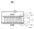
次に、実施例に係るp型熱電変換材料を用いた熱電変換モジュールについて説明する。図1は、実施例に係る熱電変換モジュールの構成を示す断面図である。図1に示す熱電変換モジュールは、上部基板14aと下部基板14bとの間に、p型熱電変換素子11と、n型熱電変換素子12とが設けられている。p型熱電変換素子11は、p型熱電変換材料を含んで形成されており、n型熱電変換素子12は、n型熱電変換材料を含んで形成されている。一つ以上のp型熱電変換素子11は、上記した実施例に係るp型熱電変換材料により形成されている。<Thermoelectric conversion module>
Next, a thermoelectric conversion module using the p-type thermoelectric conversion material according to the example will be described. FIG. 1 is a cross-sectional view illustrating a configuration of a thermoelectric conversion module according to an embodiment. In the thermoelectric conversion module shown in FIG. 1, a p-type
p型熱電変換素子11とn型熱電変換素子12とは、上部基板14aと下部基板14bとの間に、互いに交互に配列されており、π型の構造を一組の熱電変換素子対15として、上部基板14a上に形成された上部電極13a及び下部基板14b上に形成された下部電極13bにより、電気的に直列に接続されている。
The p-type
具体的には、p型熱電変換素子11は、上部電極13aにより、上部基板14a側の面においてn型熱電変換素子12と接続されている。また、p型熱電変換素子11は、下部基板14b側の面において、下部電極13bにより、上部電極13aにより接続されたn型熱電変換素子12と反対側に設けられたn型熱電変換素子12と接続されている。なお、p型熱電変換素子11とn型熱電変換素子12とは、互いに所定の間隔を設けた状態で交互に配列されており、両者は直接には接触していない。
Specifically, the p-type
上部電極13aと、p型熱電変換素子11及びn型熱電変換素子12との間、並びに下部電極13bと、p型熱電変換素子11及びn型熱電変換素子12との間は、それぞれ導電性材料により接続されている。これらの構造には、応力緩和構造を設けてもよいし、その他の付属品を付けることも可能である。
Between the
以上説明した構造により、p型熱電変換素子11及びn型熱電変換素子12と、上部電極13a及び下部電極13bとは、熱的に接触するように接合されており、上部電極13a及び下部電極13bと、上部基板14a及び下部基板14bとは、熱的に接触するように接合されている。
With the structure described above, the p-type
図1に示す熱電変換モジュールは、例えば上部基板14aを加熱するか又は高熱部に接触させることで、p型熱電変換素子11及びn型熱電変換素子12において、同一の方向に温度勾配を発生させることができる。このとき、ゼーベック効果の原理より、p型熱電変換素子11及びn型熱電変換素子12では、それぞれ、温度勾配に沿って互いに逆向きに熱起電力が発生する。これにより、大きい熱起電力を発生させることができる。
The thermoelectric conversion module shown in FIG. 1 generates a temperature gradient in the same direction in the p-type
従って、温度勾配が印加された状態で、電極の両端(例えば図1では、図中右端の下部電極13bと図中左端の下部電極13b)を接続することで、電気エネルギーを効率よく取り出すことができる。
Accordingly, electrical energy can be efficiently extracted by connecting both ends of the electrode (for example, in FIG. 1, the
n型熱電変換素子12としては、n型熱電変換材料として、Fe2TiSi系のフルホイスラー合金を用いてもよいし、Fe2VAl系フルホイスラー合金を用いてもよいし、Bi−Te系半導体を用いてもよい。中でも、Fe2TiSi系のフルホイスラー合金をn型熱電変換材料として用いた場合には、高い機械的特性や高い性能指数ZTを得られる温度領域が、上記した実施例に係るp型熱電変換材料において高い機械的特性や高い性能指数ZTを得られる温度領域と、略同程度となる。このため、熱電変換モジュールとしての出力特性や信頼性を向上させ、かつコストを低減する観点から、n型熱電変換素子として、Fe2TiSi系のフルホイスラー合金を用いることが好ましい。As the n-type
<実験例1>
以下に、実施例に係るp型熱電変換材料を、実験例1により詳細に説明する。まず、以下の方法により、実施例に係るp型熱電変換材料として、E12E2E3で表されるL21型結晶構造を有するフルホイスラー合金を作製した。<Experimental example 1>
Below, the p-type thermoelectric conversion material which concerns on an Example is demonstrated in detail by Experimental example 1. FIG. First, a full Heusler alloy having an L2 1 type crystal structure represented by E1 2 E2E3 was produced as a p-type thermoelectric conversion material according to the example by the following method.
E1サイト、E2サイト及びE3サイトの各サイトの主成分を構成する原料粉末としては、それぞれ、鉄(Fe)、チタン(Ti)及びシリコン(Si)を主成分とする原料粉末を用いた。また、E3サイトに添加する成分の原料粉末として、アルミニウム(Al)を主成分とする原料粉末を用いた。これらの原料粉末を、最終的に得られる熱電変換材料が表1の組成となるように秤量した。 As the raw material powder constituting the main components of the E1 site, E2 site, and E3 site, raw material powders mainly containing iron (Fe), titanium (Ti), and silicon (Si) were used. Moreover, the raw material powder which has aluminum (Al) as a main component was used as a raw material powder of the component added to E3 site. These raw material powders were weighed so that the finally obtained thermoelectric conversion material had the composition shown in Table 1.
次に、これらの原料粉末を、不活性ガス雰囲気中において、ステンレス鋼製の容器に入れ、直径10mmのステンレス鋼製ボール又はクロム鋼製ボールと混合した。次に、この混合物について、遊星ボールミル装置を用いたメカニカルアロイングを行い、アモルファス化した合金粉末を得た。メカニカルアロイングは、350rpmの公転回転速度で20時間以上実施した。 Next, these raw material powders were put in a stainless steel container in an inert gas atmosphere and mixed with stainless steel balls or chrome steel balls having a diameter of 10 mm. Next, the mixture was mechanically alloyed using a planetary ball mill apparatus to obtain an amorphous alloy powder. Mechanical alloying was performed at a revolution speed of 350 rpm for 20 hours or more.
次に、アモルファス化した合金粉末を、カーボン製のダイス又はタングステンカーバイド製のダイスに入れ、不活性ガス雰囲気中において、1.5GPaの圧力下でパルス電流をかけながら加熱して、焼結させた。加熱処理は、660℃まで昇温した後、その目標温度(660℃)で30分間保持して行った。その後、得られた焼結体を室温まで冷却して、熱電変換材料(試料1〜試料11)を得た。得られた試料1〜試料11について、それぞれの直径、高さ及び重量を計測し、重量を体積で除することにより、相対密度を得た。その結果、試料1〜試料11のいずれも、相対密度は85%以上であった。 Next, the amorphized alloy powder was placed in a carbon die or tungsten carbide die, and heated and sintered in an inert gas atmosphere under a pressure of 1.5 GPa while applying a pulse current. . The heat treatment was performed by raising the temperature to 660 ° C. and then maintaining the target temperature (660 ° C.) for 30 minutes. Thereafter, the obtained sintered body was cooled to room temperature to obtain thermoelectric conversion materials (Sample 1 to Sample 11). About the obtained samples 1-11, each diameter, height, and weight were measured, and the relative density was obtained by remove | dividing a weight by a volume. As a result, all of Sample 1 to Sample 11 had a relative density of 85% or more.
[評価方法]
次に、得られた各熱電変換材料のゼーベック係数及び電気伝導率を、熱電特性評価装置(「ZEM−2」、アドバンス理工株式会社製)により測定し、熱伝導率をレーザーフラッシュ法熱定数測定装置(「LFA447 Nanoflush」、ネッチジャパン株式会社製)により測定して、各試料の性能指数ZTを算出した。また、示差走査熱量計(「Thermo Plus DSC8270」、株式会社リガク製)による測定を行い、各試料の結晶化発熱量を算出した。示差走査熱量計を用いた測定は、Arフロー雰囲気中で昇温速度10℃/分、測定温度範囲を室温から900℃の条件下で行った。結晶化発熱量は、フルホイスラー合金の結晶化に伴う発熱ピークの積分値を試料重量で割り、J/gの単位で算出した。[Evaluation methods]
Next, the Seebeck coefficient and electrical conductivity of each obtained thermoelectric conversion material are measured by a thermoelectric property evaluation apparatus (“ZEM-2”, manufactured by Advance Riko Co., Ltd.), and the thermal conductivity is measured by a laser flash method thermal constant. The performance index ZT of each sample was calculated by measurement with an apparatus (“LFA447 Nanoflush”, manufactured by Netch Japan Co., Ltd.). Moreover, the measurement by the differential scanning calorimeter ("Thermo Plus DSC8270", Rigaku Co., Ltd. product) was performed, and the crystallization calorific value of each sample was calculated. Measurement using a differential scanning calorimeter was performed in an Ar flow atmosphere under a temperature rising rate of 10 ° C./min and a measurement temperature range of room temperature to 900 ° C. The calorific value of crystallization was calculated in units of J / g by dividing the integral value of the exothermic peak accompanying crystallization of the full Heusler alloy by the sample weight.
これらの評価結果を図2〜図4に示す。なお、図2〜図3において、従来のp型フルホイスラー合金の性能指数ZTの最大値である0.13を、実施例と比較例との境界として、図中破線で示した。 These evaluation results are shown in FIGS. 2 to 3, 0.13, which is the maximum value of the figure of merit ZT of the conventional p-type full Heusler alloy, is indicated by a broken line in the figure as a boundary between the example and the comparative example.
[評価結果]
図2では、M量(Si量+Al量)を26.76原子%で固定し、Fe量を49.5原子%から53.5原子%まで増加させ、その分Ti量を減少させたときの性能指数ZTを示している(試料1〜試料6)。図2では、いずれも、Si量を23.01原子%、Al量を3.75原子%とした。[Evaluation results]
In FIG. 2, the amount of M (Si amount + Al amount) is fixed at 26.76 atomic%, the amount of Fe is increased from 49.5 atomic% to 53.5 atomic%, and the Ti amount is decreased accordingly. The figure of merit ZT is shown (Sample 1 to Sample 6). In FIG. 2, the Si content is 23.01 atomic% and the Al content is 3.75 atomic%.
図2に示すように、Fe量が50原子%超52.5原子%以下の組成領域では、従来のp型フルホイスラー合金の最大性能指数ZTである0.13を超える性能指数ZTを得られている。このような、Fe量が50原子%超の範囲における性能指数ZTの向上の主な要因は、Fe量の増加に伴う電子構造の変化により、ゼーベック係数が増加したことである。図2に示すように、50.75≦x≦52の範囲では、ZT>0.15が得られており、51≦x≦51.5の範囲では、ZT>0.17が得られている。 As shown in FIG. 2, a performance index ZT exceeding 0.13, which is the maximum performance index ZT of the conventional p-type full Heusler alloy, can be obtained in the composition region where the Fe content is more than 50 atomic% and not more than 52.5 atomic%. ing. The main factor for the improvement of the figure of merit ZT in the range where the Fe content exceeds 50 atomic% is that the Seebeck coefficient has increased due to the change in the electronic structure accompanying the increase in the Fe content. As shown in FIG. 2, ZT> 0.15 is obtained in the range of 50.75 ≦ x ≦ 52, and ZT> 0.17 is obtained in the range of 51 ≦ x ≦ 51.5. .
図3では、Fe量を、図2において最大の性能指数ZTを示した51原子%に固定し、Ti量を19.75原子%から26原子%まで増加させ、その分Si量を減少させたときの性能指数ZTを示している(試料3、試料7〜試料11)。図3では、E3サイトに添加するAl量は3.75原子%に固定した。 In FIG. 3, the Fe content is fixed at 51 atomic%, which shows the maximum figure of merit ZT in FIG. 2, and the Ti content is increased from 19.75 atomic% to 26 atomic%, and the Si content is decreased accordingly. The figure of merit ZT is shown (Sample 3, Sample 7 to Sample 11). In FIG. 3, the amount of Al added to the E3 site was fixed at 3.75 atomic%.
図3に示すように、Ti量が20≦y≦24.5の組成領域では、従来のp型フルホイスラー合金の最大性能指数ZTである0.13を超える性能指数ZTを得られている。また、20.5≦y≦24.25の範囲では、ZT>0.15が得られており、21≦y≦24の範囲では、ZT>0.17が得られている。このような、このTi量の増加に伴う性能指数ZTの向上の主な要因は、結晶性の向上により電気抵抗率が減少したことである。熱電変換材料の結晶性は、示差走査熱量計を用いて得られるホイスラー合金の結晶化発熱量の大きさによって評価することが出来る。 As shown in FIG. 3, in the composition region where the amount of Ti is 20 ≦ y ≦ 24.5, a figure of merit ZT exceeding 0.13 which is the maximum figure of merit ZT of the conventional p-type full Heusler alloy is obtained. In the range of 20.5 ≦ y ≦ 24.25, ZT> 0.15 is obtained, and in the range of 21 ≦ y ≦ 24, ZT> 0.17 is obtained. The main factor for the improvement of the figure of merit ZT accompanying the increase in the amount of Ti is the decrease in electrical resistivity due to the improvement in crystallinity. The crystallinity of the thermoelectric conversion material can be evaluated by the magnitude of the crystallization calorific value of the Heusler alloy obtained using a differential scanning calorimeter.
図4では、図3において性能指数ZTを評価した、試料3及び試料7〜試料11についての、結晶化発熱量の評価結果を示している。図4に示すように、試料3及び試料7〜試料11のうち、図3において最大の性能指数ZTを示している試料9(Ti量23.5%)において、最も大きい結晶化発熱量を得られている。 FIG. 4 shows the crystallization heat generation evaluation results for Sample 3 and Samples 7 to 11 for which the figure of merit ZT was evaluated in FIG. As shown in FIG. 4, among Sample 3 and Samples 7 to 11, the largest crystallization heat generation was obtained in Sample 9 (Ti amount 23.5%) showing the maximum figure of merit ZT in FIG. It has been.
<実験例2>
次に、実験例2について説明する。実験例2では、実験例1で用いたのと同様の原料粉末を、最終的に得られる熱電変換材料が表2の組成となるように秤量し、実験例1と同じ作製プロセスを用いて熱電変換材料を得た(試料12〜試料22)。得られた試料12〜試料22について、それぞれの直径、高さ及び重量を計測し、重量を体積で除することにより、相対密度を得た。その結果、試料12〜試料22のいずれも、相対密度は85%以上であった。<Experimental example 2>
Next, Experimental Example 2 will be described. In Experimental Example 2, the same raw material powder as that used in Experimental Example 1 was weighed so that the finally obtained thermoelectric conversion material had the composition shown in Table 2, and the same production process as in Experimental Example 1 was used. Conversion materials were obtained (
なお、表2の(試料12〜試料22)は、Fe51Ti23.5Si25.5Albをベースの組成として、Al量を増加させ、その分Si量を減らしたものである。得られた熱電変換材料について、実験例1と同様の手法及び同様の条件にて、性能指数ZTを評価した。評価結果を図5に示す。In Table 2, (
[評価結果]
図5に示すように、Al量が2.5≦b≦9の組成領域では、従来のp型フルホイスラー合金の最大性能指数ZTである0.13を超える性能指数ZTを得られている。Al添加を行い、キャリアとなるホールを増加させることでp型に最適なキャリア濃度に調整することができ、p型として高い性能指数ZTを得ることが出来る。図5に示すように、3≦b≦8.5の範囲では、ZT>0.15が得られており、3.5≦b≦8の範囲では、ZT>0.17が得られている。[Evaluation results]
As shown in FIG. 5, in the composition region where the Al content is 2.5 ≦ b ≦ 9, a figure of merit ZT exceeding 0.13 which is the maximum figure of merit ZT of the conventional p-type full Heusler alloy is obtained. By adding Al and increasing the number of holes serving as carriers, the carrier concentration can be adjusted to the optimum for the p-type, and a high figure of merit ZT can be obtained for the p-type. As shown in FIG. 5, ZT> 0.15 is obtained in the range of 3 ≦ b ≦ 8.5, and ZT> 0.17 is obtained in the range of 3.5 ≦ b ≦ 8. .
11…p型熱電変換素子、12…n型熱電変換素子、13a…上部電極、13b…下部電極、14a…上部基板、14b…下部基板、15…熱電変換素子対
DESCRIPTION OF
Claims (14)
FexTiyMAaMBb …(1)
(式(1)中、MAは、Si、Sn及びGeからなる群から選択される1種の元素であり、MBは、Al、Ga及びInからなる群から選択される1種の元素であり、x、y、a、bは、それぞれ原子%でx+y+a+b=100、a+b=z、50<x≦52.5、20≦y≦24.5、24.5≦z≦29、a>0、b>0を満足する数である。)A p-type thermoelectric conversion material having a full Heusler alloy having a composition represented by the following general formula (1) and having a relative density of 85% or more.
Fe x Ti y MA a MB b ... (1)
(In formula (1), MA is one element selected from the group consisting of Si, Sn and Ge, and MB is one element selected from the group consisting of Al, Ga and In. , X, y, a, and b are atomic% x + y + a + b = 100, a + b = z, 50 <x ≦ 52.5, 20 ≦ y ≦ 24.5, 24.5 ≦ z ≦ 29, a> 0, It is a number satisfying b> 0.)
FexTiyMAaMBb …(1)
(式(1)中、MAは、Si、Sn及びGeからなる群から選択される1種の元素であり、MBは、Al、Ga及びInからなる群から選択される1種の元素であり、x、y、a、bは、それぞれ原子%でx+y+a+b=100、a+b=z、50<x≦52.5、20≦y≦24.5、24.5≦z≦29、a>0、b>0を満足する数である。)A thermoelectric conversion module having a plurality of thermoelectric conversion elements and an electrode for electrically connecting the thermoelectric conversion elements, wherein the thermoelectric conversion element has a full composition represented by the following general formula (1) A p-type thermoelectric conversion element including a p-type thermoelectric conversion material having a Heusler alloy and a relative density of 85% or more; and an n-type thermoelectric conversion element connected to the p-type thermoelectric conversion element by the electrode. A thermoelectric conversion module characterized by that.
Fe x Ti y MA a MB b ... (1)
(In formula (1), MA is one element selected from the group consisting of Si, Sn and Ge, and MB is one element selected from the group consisting of Al, Ga and In. , X, y, a, and b are atomic% x + y + a + b = 100, a + b = z, 50 <x ≦ 52.5, 20 ≦ y ≦ 24.5, 24.5 ≦ z ≦ 29, a> 0, It is a number satisfying b> 0.)
前記Fe原料粉末、前記Ti原料粉末、前記MA原料粉末及び前記MB原料粉末を混合してFe、Ti、MA、及びMBを含む混合物を調製し、該混合物をアモルファス化してアモルファス化された合金とし、
前記アモルファス化された合金を加熱して、下記一般式(1)で表される組成を有するフルホイスラー合金を有し、かつ相対密度が85%以上であるp型熱電変換材料を製造することを特徴とするp型熱電変換材料の製造方法。
FexTiyMAaMBb …(1)
(式(1)中、MAは、Si、Sn及びGeからなる群から選択される1種の元素であり、MBは、Al、Ga及びInからなる群から選択される1種の元素であり、x、y、a、bは、それぞれ原子%でx+y+a+b=100、a+b=z、50<x≦52.5、20≦y≦24.5、24.5≦z≦29、a>0、b>0を満足する数である。)Prepare Fe raw material powder, Ti raw material powder, MA raw material powder, MB raw material powder in proportions according to the target composition,
The Fe raw material powder, the Ti raw material powder, the MA raw material powder and the MB raw material powder are mixed to prepare a mixture containing Fe, Ti, MA, and MB, and the mixture is amorphized to obtain an amorphous alloy. ,
The amorphous alloy is heated to produce a p-type thermoelectric conversion material having a full Heusler alloy having a composition represented by the following general formula (1) and having a relative density of 85% or more. A method for producing a p-type thermoelectric conversion material.
Fe x Ti y MA a MB b ... (1)
(In formula (1), MA is one element selected from the group consisting of Si, Sn and Ge, and MB is one element selected from the group consisting of Al, Ga and In. , X, y, a, and b are atomic% x + y + a + b = 100, a + b = z, 50 <x ≦ 52.5, 20 ≦ y ≦ 24.5, 24.5 ≦ z ≦ 29, a> 0, It is a number satisfying b> 0.)
Applications Claiming Priority (3)
| Application Number | Priority Date | Filing Date | Title |
|---|---|---|---|
| JP2017008683 | 2017-01-20 | ||
| JP2017008683 | 2017-01-20 | ||
| PCT/JP2017/047130 WO2018135286A1 (en) | 2017-01-20 | 2017-12-27 | P-type thermoelectric conversion material, thermoelectric conversion module, and method for producing p-type thermoelectric conversion material |
Publications (2)
| Publication Number | Publication Date |
|---|---|
| JPWO2018135286A1 JPWO2018135286A1 (en) | 2019-07-04 |
| JP6617840B2 true JP6617840B2 (en) | 2019-12-11 |
Family
ID=62908304
Family Applications (1)
| Application Number | Title | Priority Date | Filing Date |
|---|---|---|---|
| JP2018563259A Active JP6617840B2 (en) | 2017-01-20 | 2017-12-27 | P-type thermoelectric conversion material, thermoelectric conversion module, and method for producing p-type thermoelectric conversion material |
Country Status (4)
| Country | Link |
|---|---|
| US (1) | US10833236B2 (en) |
| EP (1) | EP3573115B1 (en) |
| JP (1) | JP6617840B2 (en) |
| WO (1) | WO2018135286A1 (en) |
Families Citing this family (2)
| Publication number | Priority date | Publication date | Assignee | Title |
|---|---|---|---|---|
| JP7215049B2 (en) * | 2018-09-28 | 2023-01-31 | 日立金属株式会社 | Thermoelectric conversion module |
| CN111211214A (en) * | 2020-01-09 | 2020-05-29 | 中国科学院上海硅酸盐研究所 | Interface barrier layer for half-heusler alloy thermoelectric material |
Family Cites Families (9)
| Publication number | Priority date | Publication date | Assignee | Title |
|---|---|---|---|---|
| JP2004006206A (en) * | 2001-09-28 | 2004-01-08 | Toshiba Corp | Negative electrode material for nonaqueous electrolyte battery, negative electrode, nonaqueous electrolyte battery, and manufacturing method of negative electrode material |
| WO2004049464A1 (en) | 2002-11-28 | 2004-06-10 | Sumitomo Electric Industries, Ltd. | Thermoelectric material and method for producing same |
| CN1969354B (en) * | 2004-04-21 | 2012-01-11 | 昭和电工株式会社 | Process for producing a heusler alloy, a half heusler alloy, a filled skutterudite based alloy and thermoelectric conversion system using them |
| JP5723591B2 (en) * | 2010-12-28 | 2015-05-27 | 株式会社日立製作所 | Thermoelectric conversion materials and electric field applied thermoelectric conversion elements |
| JP5663422B2 (en) * | 2011-07-11 | 2015-02-04 | 株式会社日立製作所 | Thermoelectric conversion element |
| US20140345663A1 (en) | 2011-12-21 | 2014-11-27 | Jun Hayakawa | Thermoelectric device and thermoelectric module using the same |
| JP6252413B2 (en) | 2013-11-19 | 2017-12-27 | 日立金属株式会社 | Thermoelectric conversion material and thermoelectric conversion module using the same |
| CN107534078B (en) * | 2015-05-15 | 2019-12-17 | 日立金属株式会社 | Thermoelectric conversion material |
| JP6266175B2 (en) * | 2015-05-29 | 2018-01-24 | 株式会社日立製作所 | Thermoelectric conversion material |
-
2017
- 2017-12-27 US US16/461,519 patent/US10833236B2/en active Active
- 2017-12-27 WO PCT/JP2017/047130 patent/WO2018135286A1/en unknown
- 2017-12-27 JP JP2018563259A patent/JP6617840B2/en active Active
- 2017-12-27 EP EP17892783.6A patent/EP3573115B1/en active Active
Also Published As
| Publication number | Publication date |
|---|---|
| US10833236B2 (en) | 2020-11-10 |
| EP3573115A1 (en) | 2019-11-27 |
| EP3573115B1 (en) | 2021-04-07 |
| JPWO2018135286A1 (en) | 2019-07-04 |
| EP3573115A4 (en) | 2020-09-02 |
| WO2018135286A1 (en) | 2018-07-26 |
| US20190348594A1 (en) | 2019-11-14 |
Similar Documents
| Publication | Publication Date | Title |
|---|---|---|
| EP2242121B1 (en) | Thermoelectric conversion material and thermoelectric conversion module | |
| JP4745183B2 (en) | Thermoelectric conversion material and thermoelectric conversion module using the same | |
| JP2005116746A (en) | Thermoelectric conversion material and thermoelectric convertor | |
| US20180294394A1 (en) | Thermoelectric conversion material | |
| JP6617840B2 (en) | P-type thermoelectric conversion material, thermoelectric conversion module, and method for producing p-type thermoelectric conversion material | |
| JP5099976B2 (en) | Method for producing thermoelectric conversion material | |
| JP2004119647A (en) | Thermoelectric conversion material and thermoelectric conversion element using it | |
| US20230284532A1 (en) | Alloy, sintered article, thermoelectric module and method for the production of a sintered article | |
| US20130256608A1 (en) | METAL MATERIAL HAVING n-TYPE THERMOELECTRIC CONVERSION CAPABILITY | |
| EP2894681B1 (en) | METAL MATERIAL HAVING n-TYPE THERMOELECTRIC CONVERSION PERFORMANCE | |
| WO2014167801A1 (en) | Method for producing thermoelectric converting material | |
| JP5563024B2 (en) | Thermoelectric conversion material and thermoelectric conversion module using the same | |
| JP7087362B2 (en) | Manufacturing method of p-type thermoelectric conversion material, thermoelectric conversion module and p-type thermoelectric conversion material | |
| US9761779B2 (en) | Thermoelectric conversion material | |
| JP7020309B2 (en) | Thermoelectric conversion material, thermoelectric conversion module using it, and its manufacturing method | |
| JP7028076B2 (en) | Manufacturing method of p-type thermoelectric conversion material, thermoelectric conversion module and p-type thermoelectric conversion material | |
| JP2004296473A (en) | Thermoelectric conversion material for thermal power generation, and manufacturing method thereof | |
| JP2004296480A (en) | Thermoelectric conversion material and manufacturing method thereof | |
| JPWO2018225388A1 (en) | Thermoelectric conversion material, thermoelectric conversion element, and method of manufacturing thermoelectric conversion material | |
| JP5269121B2 (en) | Thermoelectric conversion material and thermoelectric conversion element using the same | |
| JP2004104015A (en) | Thermoelectric conversion material and thermoelectric conversion element using the material | |
| Liu et al. | Economical FeSi2-SiGe Composites for Thermoelectric Power Generation |
Legal Events
| Date | Code | Title | Description |
|---|---|---|---|
| A621 | Written request for application examination |
Free format text: JAPANESE INTERMEDIATE CODE: A621 Effective date: 20190208 |
|
| TRDD | Decision of grant or rejection written | ||
| A01 | Written decision to grant a patent or to grant a registration (utility model) |
Free format text: JAPANESE INTERMEDIATE CODE: A01 Effective date: 20191015 |
|
| A61 | First payment of annual fees (during grant procedure) |
Free format text: JAPANESE INTERMEDIATE CODE: A61 Effective date: 20191028 |
|
| R150 | Certificate of patent or registration of utility model |
Ref document number: 6617840 Country of ref document: JP Free format text: JAPANESE INTERMEDIATE CODE: R150 |
|
| S531 | Written request for registration of change of domicile |
Free format text: JAPANESE INTERMEDIATE CODE: R313531 |
|
| S533 | Written request for registration of change of name |
Free format text: JAPANESE INTERMEDIATE CODE: R313533 |
|
| R350 | Written notification of registration of transfer |
Free format text: JAPANESE INTERMEDIATE CODE: R350 |