JP6617656B2 - Game machine - Google Patents
Game machine Download PDFInfo
- Publication number
- JP6617656B2 JP6617656B2 JP2016148009A JP2016148009A JP6617656B2 JP 6617656 B2 JP6617656 B2 JP 6617656B2 JP 2016148009 A JP2016148009 A JP 2016148009A JP 2016148009 A JP2016148009 A JP 2016148009A JP 6617656 B2 JP6617656 B2 JP 6617656B2
- Authority
- JP
- Japan
- Prior art keywords
- game
- game ball
- arc
- game area
- area
- Prior art date
- Legal status (The legal status is an assumption and is not a legal conclusion. Google has not performed a legal analysis and makes no representation as to the accuracy of the status listed.)
- Active
Links
- 230000002265 prevention Effects 0.000 claims description 5
- 238000011144 upstream manufacturing Methods 0.000 claims description 5
- 238000005034 decoration Methods 0.000 description 13
- 238000005096 rolling process Methods 0.000 description 5
- 238000012986 modification Methods 0.000 description 3
- 230000004048 modification Effects 0.000 description 3
- 230000001105 regulatory effect Effects 0.000 description 3
- 230000007423 decrease Effects 0.000 description 2
- 230000000694 effects Effects 0.000 description 2
- 239000011521 glass Substances 0.000 description 2
- 238000007599 discharging Methods 0.000 description 1
- 239000004973 liquid crystal related substance Substances 0.000 description 1
- 230000002093 peripheral effect Effects 0.000 description 1
Images


Landscapes
- Pinball Game Machines (AREA)
Description
本発明は、遊技板の前面に遊技球が流下可能な遊技領域を有し、その遊技領域内に遊技板の前面から突出した遊技領域内突壁を備えた遊技機に関する。 The present invention relates to a gaming machine having a game area in which a game ball can flow down on the front surface of a game board, and a game area inner wall protruding from the front surface of the game board in the game area.
従来、この種の遊技機として、遊技領域内突壁が表示装置を囲むように設けられていて、その遊技領域内突壁の左上部には、遊技領域に撃ち込まれた遊技球を受け止めて下方へと案内する凹部が形成されたものが知られている。凹部に受け止められた遊技球は、遊技領域内突壁上を転動した後、遊技領域における左側流下領域へと向かい、左側流下領域に配置された複数の釘によってランダムに下方へと流下していく(例えば、特許文献1参照)。 Conventionally, as a gaming machine of this type, a game area inner wall is provided so as to surround the display device, and the upper left of the game area inner wall receives a game ball shot into the game area and moves downward. The thing in which the recessed part which guides to is formed is known. The game ball received by the recess rolls on the protruding wall in the game area, then moves to the left flow area in the game area, and randomly flows downward by a plurality of nails arranged in the left flow area. (For example, refer to Patent Document 1).
しかしながら、上述した従来の遊技機では、遊技球が遊技領域内突壁から左側流下領域へと流下する際に、勢いよく釘に衝突し、度重なる衝突の結果、釘が破損してしまうという問題があった。 However, in the conventional gaming machine described above, when the game ball flows down from the protruding wall in the game area to the left-side down area, the nail vigorously collides and the nail is damaged as a result of repeated collisions. was there.
本発明は、上記事情に鑑みてなされたもので、遊技球の衝突による釘への負荷を軽減することが可能な遊技機の提供を目的とする。 The present invention has been made in view of the above circumstances, and an object of the present invention is to provide a gaming machine capable of reducing a load on a nail due to a collision of game balls.
上記目的を達成するためになされた請求項1の発明は、遊技球が流下可能な遊技領域を前面に備え、複数の釘が打ち込まれた遊技板と、前記遊技領域を包囲する包囲壁と、前記遊技領域内に遊技球を進入させるための進入口と、前記遊技領域を流下する遊技球が前記進入口から逆流することを規制する球戻り防止部材と、前記包囲壁の一部をなし、前記進入口から下方へ円弧状に延びた円弧レールと、前記遊技板の前面から突出し、前記遊技領域に打ち込まれた遊技球を下方へと案内可能な遊技領域内突壁と、を備えた遊技機において、前記遊技領域内突壁の左外側面には、前記円弧レールと並んで延びる左サイド部と、前記左サイド部より上流側に設けられ、左下がりに傾斜した左上傾斜部と、前記左上傾斜部と前記左サイド部との間を接続し、前記左上傾斜部全体の勾配より緩い勾配で左下がりに傾斜した段差傾斜部と、が備えられ、これら前記左サイド部、前記段差傾斜部及び前記左上傾斜部には、前記遊技領域側に遊技球1球分程度の幅で張り出し、前記遊技板の上に重ねられるフランジ部が設けられ、前記球戻り防止部材は、前記進入口を開閉する開閉部材と、前記開閉部材を支持する支持ベースと、を備え、前記支持ベースは、前記左サイド部の上端部と対向し、前記遊技領域は、前記支持ベースと前記左サイド部の上端部との間に形成された絞り部と、前記絞り部の上流側に位置し、前記円弧レールの上端部と前記段差傾斜部との間に形成された拡張部と、を有し、前記フランジ部の外縁部に沿って複数の前記釘が配設され、かつ前記拡張部及び前記絞り部には、前記釘が配設されていない、ことを特徴とする遊技機である。
請求項2の発明は、前記フランジ部の外縁部に沿って配設される前記釘により遊技球の前記フランジ部への進入が規制される規制部が複数形成されると共に、複数の前記規制部の間には遊技球の前記フランジ部への進入を許容する遊技球1球分の幅の進入部が形成されている、ことを特徴とする請求項1に記載の遊技機である。
In order to achieve the above object, the invention of
The invention according to
この構成によれば、左上傾斜部が左上傾斜部より勾配の緩い段差傾斜部に連絡しているので、左上傾斜部上を転動した遊技球が段差傾斜部に至ると、段差傾斜部に衝突して遊技球の流下速度が落ちる。これにより、遊技領域内突壁から流下する遊技球の流下速度を抑えることが可能となる。 According to this configuration, since the upper left inclined portion communicates with the step inclined portion having a gentler slope than the upper left inclined portion, when the game ball rolling on the upper left inclined portion reaches the step inclined portion, it collides with the step inclined portion. As a result, the flow speed of the game ball drops. Thus, it is possible to suppress the flow-down speed of the game balls flowing down from the gaming area protruding wall.
本発明によれば、左上傾斜部が左上傾斜部より勾配の緩い段差傾斜部に連絡しているので、左上傾斜部上を転動した遊技球を段差傾斜部にて流下速度を落とすことができ、遊技領域内突壁から流下する遊技球の流下速度を抑えて、釘にかかる負荷を軽減することが可能となる。 According to the present invention, since the upper left inclined portion is connected to the step inclined portion having a gentler slope than the upper left inclined portion, the flow velocity of the game ball rolling on the upper left inclined portion can be reduced at the step inclined portion. , to suppress the flow-down speed of the game balls to or below al stream gaming area protruding wall, it is possible to reduce the load on the nail.
以下、本発明をパチンコ遊技機に適用した一実施形態を図1〜図6に基づいて説明する。図1に示すように、本実施形態に係るパチンコ遊技機10(以下、単に、「遊技機10」という。)は、図2に示す遊技板11を、遊技機10の前面に開閉可能に取り付けられた前面枠10Zで覆ってなり、その前面枠10Zに形成されたガラス窓10Wを通して、遊技板11の前面に形成された遊技領域R1の全体が視認可能となっている。
Hereinafter, an embodiment in which the present invention is applied to a pachinko gaming machine will be described with reference to FIGS. As shown in FIG. 1, the
前面枠10Zのうちガラス窓10Wより下方には、上皿26と下皿27が上下2段にして設けられ、下皿27の右側には、操作ハンドル28が備えられている。操作ハンドル28を回動操作すると、上皿26に収容された遊技球が遊技領域R1に向けて弾き出される。なお、上皿26に備えた球排出ボタン(図示せず)を押すと上皿26に収容されている遊技球が下皿27へと移動する。
An
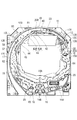
図2に示すように、遊技板11の前面からは、遊技領域R1を包囲するガイドレール12(本発明の「包囲壁」に相当する。)が突出している。ガイドレール12は、円弧状に湾曲した第1レール12A及び第2レール12Bと、緩衝部材12Cと板支持部50とで構成されている。第1レール12Aは、遊技領域R1の周縁部のうち上側の略1/4円周分を除いた部分に沿わせて配置され、第1レール12Aの左側端部には板支持部50が第1レール12Aを延長してなる架空円弧に沿って配置されている。第2レール12Bの一端部は、第1レール12Aの最下部に対して左側方に配置され、第2レール12Bの他端部は、第1レール12Aの右側端部に対して遊技球1〜2球分、上方に離れた位置に配置されている。そして、第1レール12Aと第2レール12Bとの右側端部同士の間は、例えば、樹脂製の緩衝部材12Cによって閉塞されている。また、板支持部50と第2レール12Bの中間部との間には、遊技球1〜2個分の隙間が設けられ、これにより、遊技領域R1の左上縁部に、遊技領域R1内に遊技球を進入させるための進入口12K(本発明に係る「進入部」に相当する。)が形成されている。
As shown in FIG. 2, a guide rail 12 (corresponding to the “enclosure wall” of the present invention) that surrounds the game area R <b> 1 protrudes from the front surface of the
図6に示すように、進入口12Kには、進入口12Kを塞ぐように可撓規制板12Lが突出している。可撓規制板12Lは板支持部50にて支持され、遊技球が進入口12K内に逆流することを規制している。そして、板支持部50と可撓規制板12Lにより球戻り防止部材53が構成されている。操作ハンドル28の回動操作により遊技領域R1に向けて遊技球が発射されると、遊技球が可撓規制板12Lを遊技領域R1側に撓ませて遊技領域R1内に進入し、その後、第2レール12Bのうち進入口12Kより上方部分の円弧状案内部12Dによって右斜め上方に案内される。
As shown in FIG. 6, a
図2に示すように、遊技板11のうち遊技領域R1の中央には、表示開口11Hが貫通形成されており、その表示開口11Hに遊技板11の裏面側から表示装置30が対向している。表示装置30は、例えば、液晶モジュールで構成され、その前面が遊技に関する演出を行う表示画面30Gとなっている。
As shown in FIG. 2, a display opening 11H is formed through the center of the game area R1 in the
図3に示すように、遊技板11の前面中央には、表示画面30Gを囲むように表示装飾枠23が取り付けられている。表示装飾枠23は、遊技板11の前面側から表示開口11Hに嵌め込まれて、表示開口11Hの内側に張り出すと共に、表示開口11Hの外縁部に沿って遊技板11の前面から遊技領域内突壁40を突出させている。これにより、遊技領域R1を流下する遊技球が、表示装飾枠23の前側を通過して表示装飾枠23の内側に進入しないように構成されている。
As shown in FIG. 3, a
表示装飾枠23は、図2に示すように、遊技領域R1の横方向の中間且つ上端寄り部分に配置され、遊技領域R1のうち表示装飾枠23の左側方に遊技球が流下可能な左側流下領域R2が形成される一方、表示装飾枠23の右側方に遊技球が流下可能な右側流下領域R4が形成されている。遊技領域内突壁40のうち上端部から右上部にかけては第2レール12Bに沿って延びた上側案内部41になっていて、この上側案内部41と第2レール12Bとの間に遊技球が1つずつ通過可能な上側連絡流路25Rが形成され、上側連絡流路25Rの終端部が右側流下領域R4に連絡している。また、表示装飾枠23の下方には、左側流下領域R2と右側流下領域R4とが連絡した下側流下領域R3が形成されている。
As shown in FIG. 2, the
左側流下領域R2には、風車19が設けられ、左側流下領域R2を流下してきた遊技球の進路を中央側へ変更して下側流下領域R3へと案内可能になっている。右側流下領域R4には、始動ゲート18が設けられると共に、始動ゲート18の下方に第1大入賞口15Aが設けられている。
A
下側流下領域R3の横方向中央には、第1及び第2の始動入賞口14A,14Bが上下に並べて設けられ、第1及び第2の始動入賞口14A,14Bの右側に第2大入賞口15Bが設けられている。第1及び第2の始動入賞口14A,14Bの左側及び第2大入賞口15Bの右側には、一般入賞口20が複数設けられている。また、下側流下領域R3の下端部で第2始動入賞口14Bの左右両側には、上記入賞口14A,14B,15A,15B,20の何れにも入賞しなかった遊技球を遊技領域R1の外側に排出するためのアウト口16,16が設けられている。
The first and second
遊技領域R1の全体には、遊技球の流下方向をランダムに変更するための障害釘17が多数植設されている。
A large number of
ところで、本実施形態の遊技機10では、表示装飾枠23のうち遊技領域内突壁40の左上部が、上側案内部41から左下がりに傾斜した直線部42、左上円弧部43、左サイド部45を有していて、第2レール12Bの円弧状案内部12Dとこれに対向する直線部42及び左上円弧部43との間に、進入口12Kから撃ち出された遊技球を受け入れる球導入領域R5が形成されている。球導入領域R5に受け入れられた遊技球は、障害釘17に衝突しながら下方へと流下するか又は直線部42及び左上円弧部43上を転動するかして左側流下領域R2へと流下する。以下、各部位について詳説する。
By the way, in the
図4に示すように、遊技領域内突壁40のうち直線部42から左サイド部45の範囲にかけては、フランジ部47Fが設けられている。フランジ部47Fは、遊技球1球分程度、上方に張り出しかつ遊技板11の前面に敷設され、フランジ部47F部分は障害釘17を有さない構成になっている(図2参照)。また、フランジ部47Fには、その上端部及び下端部に遊技板11へのビス留め用のビス孔40H,40Hが形成されている。
As shown in FIG. 4, a flange portion 47 </ b> F is provided in a range from the
図2に示すように、左サイド部45は、ガイドレール12のうち進入口12Kから下方に延びる円弧状の円弧レール12Eと同心をなして並行に延びている。左サイド部45と円弧レール12Eとは遊技球2球分以上の間隔を空けて対向し、この左サイド部45と円弧レール12Eとの間が本発明に係る特定領域S2になっている。なお、板支持部50及び第1レール12Aの円弧状に延びる部分が、本発明に係る円弧レール12Eに相当する。
As shown in FIG. 2, the
図4に示すように、左上円弧部43は、左サイド部45を延長してなる架空基準線K1を中心として架空基準線K1に沿って延びた遊技球2球分の幅の架空領域S1内で左上がりに傾斜して延びている。また、左上円弧部43は、2つの円弧を連ねてなり、上流側の第1円弧部43Aと下流側の第2円弧部43Bとから構成されている。これら第1及び第2の円弧部43A,43Bは、球導入領域R5に向かって膨出し、曲率が同程度に設定されている一方、長さが第2円弧部43Bの方が第2円弧部43Aに比べて長く設定されている。なお、左上円弧部43が、本発明に係る「左上傾斜部」に相当する。本実施形態では、左上円弧部43が2つの円弧から構成されていたが、1つの円弧であってもよい。
As shown in FIG. 4, the upper
直線部42は、上側案内部41と第1円弧部43Aとの間を連絡し、直線状に延びている。また、直線部42は、左上円弧部43全体の勾配より急勾配でかつ始端部から終端部までの長さが第1及び第2の円弧部43A,43Bより短く設定されている。なお、直線部42は直線状に限らず、凹状又は凸状の曲線で構成されていてもよい。
The
さて、本実施形態では、左上円弧部43と左サイド部45との間が、本発明に係る段差傾斜部44にて連絡されている。段差傾斜部44は、第2円弧部43Bの終端部から直線状に左下がりに傾斜して延び、その勾配θ1は、左上円弧部43全体の勾配より緩やかに構成され、約5〜45度の範囲に設定することで遊技球に付与する流下速度を抑えつつ、遊技球が下方に流れ易い構成となっている。また、段差傾斜部44は、第2円弧部43Bと段差傾斜部44との一端側の交点から左サイド部45と段差傾斜部44との他端側の交点までの長さL1(第2円弧部43Bを延長した架空円弧線と段差傾斜部44を延長してなる段差基準線K2との交点から段差傾斜部44の終端部までの長さL1)が約5.5〜11[mm]に設定されている。つまり、段差傾斜部45は、少なくとも遊技球の半径以上に構成されていればよい。これにより、左上円弧部43上を転動した遊技球が段差傾斜部44に至ると、段差傾斜部44に衝突して遊技球の流下速度が落ちるので、段差傾斜部44から特定領域S2へと流下する遊技球の流下速度が抑えられる。
Now, in the present embodiment, the upper
また、本実施形態では、直線部42と第1円弧部43Aとの間及び第1円弧部43Aと第2円弧部43Bとの間に第1及び第2の窪み部46A,46Bが形成されている。これにより、段差傾斜部44へと向かう遊技球の流下速度を第1及び第2の窪み部46A,46Bによって抑えたり又は加速させることが可能となっている。なお、本実施形態では、直線部42と第1円弧部43Aとの交差部(第1窪み部46A)、第1円弧部43Aと第2円弧部43Bとの交差部(第2窪み部46B)、及び、第2円弧部43Bと段差傾斜部44との交差部は、湾曲面にて連絡されている。
In the present embodiment, the first and second
図5に示すように、特定領域S2には、フランジ部47Fの外縁部に沿って複数の障害釘17が植設され、これら障害釘17群のうち最上部に位置する障害釘17が、本発明に係る特定釘17Kになっている。特定領域S2に流下してきた遊技球は、特定釘17Kを境に、円弧レール12Eと障害釘17群との間の外側流路と、障害釘17群と左サイド部45との間の内側流路とに振り分けられる。また、特定釘17Kは段差基準線K2より僅かに下方に配置されていて、段差傾斜部44から流下した遊技球が、直接、外側流路又は内側流路へと流下するか、特定釘17Kを掠めて外側流路又は内側流路に分岐して流下するようになっている。なお、図5及び図6には、障害釘17のヘッド部17Hが実線で示され、シャフト部17Sが破線で示されている。
As shown in FIG. 5, in the specific region S2, a plurality of obstacle nails 17 are implanted along the outer edge of the
また、段差傾斜部44は、板支持部50との対向位置に配置されている。詳細には、板支持部50は、ベース部材51と、可撓規制板12Lを支持する支持部材52とから構成されている。ベース部材51は、平面形状が略長方形をなし、ビスにて遊技板11に固定されている。ベース部材51の下端寄り位置には前方に突出した円筒部51Jが設けられ、支持部材52の係合部52Jと凹凸係合して、支持部材52がベース部材51に対して揺動可能に支持されている。
Further, the step inclined
支持部材52には、係合部52Jから板支持片52Aとフック部52Bとが突出している。これら板支持片52A及びフック部52Bは、円弧レール12Eの円弧に沿って右上がりに傾斜し、板支持片52Aが第1レール12Aの遊技領域R1側の側面より外側に配置されて比較的長く延びる一方、フック部52Bが第1レール12Aの遊技領域R1側の側面より内側に配置されて比較的短く延びた後、板支持片52A側に屈曲している。そして、板支持片52Aとフック部52Bとの間のL字状の溝部分に可撓規制板12Lの下側部分が係止されて、板支持片52Aの先端から延びる可撓規制板12Lの上側部分が可撓可能に支持されている。
On the
これら構成により、板支持部50のうち、フック部52Bが左サイド部45の上端部分と対向するように配置される一方、フック部52Bより上方に延びた板支持片52Aが段差傾斜部44と対向するように配置されている。そして、板支持部50と左サイド部45の上端部分との間に絞り部S4が形成され、フック部52Bより上方に延びた板支持片52Aと段差傾斜部44との間に拡張部S3が形成されている。絞り部S4及び拡張部S3は、共に障害釘17を有さない釘無し領域になっていて、特定領域S2へと向かう遊技球の球詰まりを抑制することができる。また、障害釘17を有していないので、遊技球の流下方向の自由度が高く、流下時の接触などにより任意の流下態様とすることができる。さらに、拡張部S3は最も幅が広いところで遊技球3球分以上4球分未満の幅となっているのに対し、絞り部S4は遊技球2球分以上3球分未満の幅になっているので、特定領域S2に進入した遊技球の流下速度を絞り部S4にて落とすことができ、遊技球が特定釘17Kに衝突した場合の特定釘17Kにかかる負荷を軽減することができる。
With these configurations, of the
パチンコ遊技機10の構成に関する説明は以上である。次に、パチンコ遊技機10の作用効果について説明する。
This completes the description of the configuration of the
操作ハンドル28の回動操作により左側流下領域R2に向けて遊技球が撃ち込まれると、図6に示すように、遊技球が進入口12Kから円弧状案内部12Dによって右斜め上方に案内され、球導入領域R5に受け入れられる。受け入れられた遊技球は、球導入領域R5に植設された複数の障害釘17に衝突してジグザグに流下するか、又は、障害釘17に衝突してもしくは直接、左上円弧部43に衝突して、遊技領域内突壁40上を転動するなどして特定領域S2へと向かう。
When the game ball is shot toward the left-side down region R2 by the turning operation of the
ところで、これら遊技球のうち、遊技領域内突壁40上を転動した遊技球は、左下がりに傾斜した直線部42及び左上円弧部43により流下速度が比較的速い状態で特定釘17Kへ向かうことが考えられる。これに対し、本実施形態では、左上円弧部43と左サイド部45との間に、左上円弧部43全体の勾配より緩やかな段差傾斜部44が設けられているので、遊技領域内突壁40上を転動した遊技球が段差傾斜部44に至ると、段差傾斜部44に衝突して遊技球の流下速度が落ちる。これにより、遊技領域内突壁40から特定領域S2へと流下する遊技球の流下速度を抑えることが可能となり、特定釘17Kにかかる負荷を軽減して、特定釘17Kの破損や緩みを防止することが可能となる。
By the way, among these game balls, the game ball that rolls on the projecting
また、本実施形態では、特定領域S2の上端部に拡張部S3より幅狭な絞り部S4を設けたので、絞り部S4にて遊技球の流下速度を落とすことが可能となる。これに加えて、拡張部S3において障害釘17を有さない構成としたので、特定領域S2へと向かう遊技球の球詰まりを抑制することができる。また、遊技球の流下方向の自由度が高く、流下時の接触などにより任意の流下態様とすることができるので、遊技球同士が衝突した場合に遊技球の流下速度が落とされる。
In the present embodiment, the narrowed portion S4 narrower than the expanded portion S3 is provided at the upper end portion of the specific area S2, so that it is possible to reduce the flow speed of the game ball at the narrowed portion S4. In addition to this, since the extended portion S3 is configured not to have the
さらに、本実施形態では、特定領域S2に植設された障害釘17のうち、最上部に位置する特定釘17Kを段差基準線K2より下方に配置したので、遊技球が、直接、外側流路又は内側流路へと流下するか、特定釘17Kを掠めて外側流路又は内側流路に分岐して流下するようになっているので、特定釘17Kにかかる負荷を軽減することができる。
Further, in the present embodiment, the
このように、本実施形態によれば、遊技領域内突壁40から特定領域S2へと流下する遊技球の流下速度を抑えることができると共に、特定領域S2の上端部(絞り部S4)で遊技球の流下速度を落とすことができるので、特定釘17Kにかかる負荷を軽減することが可能となる。
As described above, according to the present embodiment, it is possible to suppress the flow speed of the game ball flowing down from the game area
また、本実施形態では、従来、遊技領域内突壁の左上部を表示開口側に膨出させて凹部としていた部分を、ガイドレール12に向かって膨出させたので、従来より表示開口11Hを大きくとることが可能となる。これにより、表示画面30Gの大型化に対応可能であると共に、可動役物の配置の自由度を高めることが可能となる。
Further, in the present embodiment, the portion that has conventionally been dented by bulging the upper left part of the projecting wall in the game area toward the display opening side is bulged toward the
さらに、本実施形態では、直線部42と第1円弧部43Aとの間及び第1円弧部43Aと第2円弧部43Bとの間に第1及び第2の窪み部46A,46Bが設けられているので、遊技領域内突壁40上を流下する遊技球の流下速度を落としたり加速させたりすることができる。これにより、遊技領域内突壁40上を流下する遊技球の流下態様の趣向性を高めることが可能となる。
Further, in the present embodiment, the first and second
[他の実施形態]
本発明は、前記実施形態に限定されるものではなく、例えば、以下に説明するような実施形態も本発明の技術的範囲に含まれ、さらに、下記以外にも要旨を逸脱しない範囲内で種々変更して実施することができる。
[Other Embodiments]
The present invention is not limited to the above-described embodiment. For example, the embodiments described below are also included in the technical scope of the present invention, and various other than the following are not deviated from the gist. It can be changed and implemented.
(1)前記実施形態では、本発明に係る左上傾斜部が第1円弧部43Aと第2円弧部43Bとから構成されていたが、架空領域S1内に収まり、下方側に向けて流下できるのであれば、円弧は一つであってもよいし、3つ以上であってもよい。
(1) In the above embodiment, the upper left inclined portion according to the present invention is composed of the
(2)また、左上傾斜部は円弧に限るものではく、図7に示す遊技領域内突壁40Vのように、左上傾斜部43Vが直線状に延びてガイドレール12側に屈曲して延びた形状であってもよい。
(2) Further, the upper left inclined portion is not limited to the circular arc, and the upper left inclined
(3)さらに、左上傾斜部は架空領域S1内に収まればよく、図8に示す遊技領域内突壁40Wのように、左上傾斜部43Wに部分的に表示開口11H側に膨出した凹部43Cを有する構成であってもよい。
(3) Furthermore, the upper left inclined portion only needs to be accommodated in the imaginary region S1, and a
(4)前記実施形態では、左サイド部45が円弧状であったが、図9に示す遊技領域内突壁40Xに示すように、左サイド部45Xが直線状をなし、左サイド部45Xを延長してなる架空基準線K1を中心とした架空領域S1内に左上円弧部43が配置された構成であってもよい。
(4) In the above-described embodiment, the
(5)前記実施形態では、特定釘17Kが段差基準線K2より下方に配置されていたが、段差基準線K2上であってもよい。
(5) In the embodiment, the
(6)前記実施形態では、段差傾斜部44が板支持部50と対向する位置(段差傾斜部44が進入口12Kより下側)に配置されていたが、段差傾斜部44を板支持部50より下方又は上方にずらして配置した構成であってもよい。
(6) In the above-described embodiment, the step inclined
(7)前記実施形態では、拡張部S3に障害釘17を有さない構成になっていたが、障害釘17を設けた構成であってもよい。
(7) In the above-described embodiment, the extension nail S3 does not have the
(8)前記実施形態では、遊技領域内突壁40が表示装置30を囲む枠形状になっていたが、遊技領域内突壁40は枠形状に限るものではない。また、表示装置30以外のものを囲む構成であってもよい。
(8) In the embodiment described above, the game area
(9)本発明には含まれないが、遊技領域内突壁40の左外側面以外の、例えば、右外側面に本発明の左上傾斜部、左サイド円弧部に相当する右上傾斜部、右サイド円弧部を設け、これら右上傾斜部と右サイド円弧部との間を段差傾斜部で連絡する構成であってもよい。
なお、上記実施形態及び他の実施形態には、以下に示す[特徴1]〜[特徴4]が含まれている。
[特徴1]
遊技球が流下可能な遊技領域を前面に備え、複数の釘が打ち込まれた遊技板と、
前記遊技領域を包囲する包囲壁と、
前記遊技領域内に遊技球を進入させるための進入部と、
前記包囲壁の一部をなし、前記進入部から下方へ円弧状に延びた円弧レールと、
前記遊技板の前面から突出し、前記遊技領域の上部に打ち込まれた遊技球を下方へと案内可能な遊技領域内突壁と、を備えた遊技機において、
前記遊技領域内突壁の左外側面には、
前記円弧レールと並んで延びる左サイド部と、
前記左サイド部を右上方へ延長してなる架空基準線を中心として前記架空基準線に沿って延びた遊技球2球分の幅の架空領域内で左下がりに傾斜した左上傾斜部と、
前記左サイド部と前記左上傾斜部との間を接続し、前記左上傾斜部全体の勾配より緩い勾配で左下がりに傾斜した段差傾斜部と、が備えられ、
前記円弧レールと前記左サイド部との間の特定領域に配設された前記複数の釘のうち最上部に位置する特定釘は、前記段差傾斜部を左下方に延長してなる段差基準線上、又は、前記段差基準線の下方に配置されている、遊技機。
特徴1によれば、左上傾斜部が左上傾斜部より勾配の緩い段差傾斜部に連絡しているので、左上傾斜部上を転動した遊技球が段差傾斜部に至ると、段差傾斜部に衝突して遊技球の流下速度が落ちる。これにより、遊技領域内突壁から特定領域へと流下する遊技球の流下速度を抑えることが可能となり、特定釘にかかる負荷を軽減することが可能となる。
[特徴2]
前記段差傾斜部は前記進入部より下方に位置する、特徴1に記載の遊技機。
段差傾斜部は、進入部より上方に位置する構成でもよいし、特徴2のように、進入部より下方に位置する構成であってもよい。特徴2によれば、進入部から遊技領域に撃ち出され、下方に流下してスピードに乗った状態の遊技球の流下速度を段差傾斜部で落とすことができるので、遊技球の緩急により趣向性の高い流下態様とすることが可能となる。
[特徴3]
前記円弧レールの上端寄り位置には、前記円弧レールの上端部から前記進入部側に張り出して前記遊技領域から前記進入部へ遊技球が逆流することを規制する可撓規制板を支持する板支持部が設けられ、
前記板支持部は、その右端面が前記円弧レールが描く円弧に沿って、かつ、前記左サイド部の上端部と対向し、
前記遊技領域は、前記板支持部と前記左サイド部の上端部との間に形成された絞り部と、前記絞り部の上流側に位置し、前記円弧レールの上端部と前記段差傾斜部との間に形成された拡張部と、を有している、特徴1又は2に記載の遊技機。
特徴3によれば、拡張部を流下する遊技球が拡張部より幅狭な絞り部を通って特定領域へ流れ込むので、絞り部に流下する際に遊技球の流下速度を落とすことが可能となる。
[特徴4]
前記拡張部には釘が配設されていない、特徴3に記載の遊技機。
特徴4によれば、拡張部における遊技球の流下態様を任意にすることが可能となる。
(9) Although not included in the present invention, other than the left outer surface of the game area
The above embodiment and other embodiments include the following [Feature 1] to [Feature 4].
[Feature 1]
A game board in which a plurality of nails are driven, with a game area in which a game ball can flow down on the front;
An encircling wall that encloses the gaming area;
An entry portion for allowing a game ball to enter the game area;
An arc rail which forms part of the surrounding wall and extends downward in an arc from the entry portion;
In a gaming machine comprising: a gaming area projecting wall that protrudes from the front surface of the gaming board and can guide a gaming ball driven into the upper part of the gaming area downward;
On the left outer surface of the game area inner wall,
A left side portion extending side by side with the arc rail;
An upper left inclined portion inclined downward to the left in an imaginary region having a width corresponding to two game balls extending along the imaginary reference line with the imaginary reference line formed by extending the left side portion to the upper right;
A step slope portion that connects between the left side portion and the upper left slope portion, and is sloped to the lower left with a gentler slope than the overall slope of the upper left slope portion, and
Among the plurality of nails disposed in the specific area between the arc rail and the left side portion, the specific nail located at the uppermost portion is on a step reference line formed by extending the step inclined portion to the lower left. Alternatively, a gaming machine disposed below the step reference line.
According to the
[Feature 2]
The gaming machine according to
The step inclined portion may be configured to be located above the entry portion, or may be configured to be located below the entry portion as in
[Feature 3]
A plate support that supports a flexible restricting plate that protrudes from the upper end portion of the arc rail toward the entry portion side and restricts a game ball from flowing backward from the game area to the entry portion at a position near the upper end of the arc rail. Part is provided,
The plate support portion has a right end surface along an arc drawn by the arc rail and is opposed to an upper end portion of the left side portion,
The game area includes a throttle formed between the plate support and the upper end of the left side, an upstream side of the throttle, and an upper end of the arc rail and the step inclined portion. The gaming machine according to
According to the
[Feature 4]
The gaming machine according to the
According to the feature 4, it is possible to make the flow-down mode of the game ball in the expansion part arbitrary.
10 パチンコ遊技機
11 遊技板
12 ガイドレール(包囲壁)
12E 円弧レール
12K 進入口(進入部)
12L 可撓規制板
17K 特定釘
40,40V,40W,40X 遊技領域内突壁
41 上側案内部
42 直線部
43 左上円弧部(左上傾斜部)
43A 第1円弧部
43B 第2円弧部
44 段差傾斜部
45,45X 左サイド部
50 板支持部
K1 架空基準線
K2 段差基準線
R1 遊技領域
R5 球導入領域
S1 架空領域
S2 特定領域
S3 拡張部
S4 絞り部
10
12L
43A
Claims (2)
前記遊技領域を包囲する包囲壁と、
前記遊技領域内に遊技球を進入させるための進入口と、
前記遊技領域を流下する遊技球が前記進入口から逆流することを規制する球戻り防止部材と、
前記包囲壁の一部をなし、前記進入口から下方へ円弧状に延びた円弧レールと、
前記遊技板の前面から突出し、前記遊技領域に打ち込まれた遊技球を下方へと案内可能な遊技領域内突壁と、を備えた遊技機において、
前記遊技領域内突壁の左外側面には、
前記円弧レールと並んで延びる左サイド部と、
前記左サイド部より上流側に設けられ、左下がりに傾斜した左上傾斜部と、
前記左上傾斜部と前記左サイド部との間を接続し、前記左上傾斜部全体の勾配より緩い勾配で左下がりに傾斜した段差傾斜部と、が備えられ、
これら前記左サイド部、前記段差傾斜部及び前記左上傾斜部には、前記遊技領域側に遊技球1球分程度の幅で張り出し、前記遊技板の上に重ねられるフランジ部が設けられ、
前記球戻り防止部材は、前記進入口を開閉する開閉部材と、前記開閉部材を支持する支持ベースと、を備え、
前記支持ベースは、前記左サイド部の上端部と対向し、
前記遊技領域は、前記支持ベースと前記左サイド部の上端部との間に形成された絞り部と、前記絞り部の上流側に位置し、前記円弧レールの上端部と前記段差傾斜部との間に形成された拡張部と、を有し、
前記フランジ部の外縁部に沿って複数の前記釘が配設され、かつ前記拡張部及び前記絞り部には、前記釘が配設されていない、ことを特徴とする遊技機である。 A game board in which a plurality of nails are driven, with a game area in which a game ball can flow down on the front;
An encircling wall that encloses the gaming area;
An entrance for allowing a game ball to enter the game area;
A ball return prevention member for restricting a game ball flowing down the game area from flowing backward from the entrance,
An arc rail which forms a part of the surrounding wall and extends downward in an arc from the entrance;
In a gaming machine comprising: a gaming area protruding wall that protrudes from the front surface of the gaming board and is capable of guiding a gaming ball driven into the gaming area downward.
On the left outer surface of the game area inner wall,
A left side portion extending side by side with the arc rail;
Provided on the upstream side of the left side portion, and an upper left inclined portion inclined downward to the left;
A step inclined portion that connects the upper left inclined portion and the left side portion, and is inclined to the lower left with a gentler gradient than the entire upper left inclined portion; and
The left side part, the step slope part, and the upper left slope part are provided with a flange part that protrudes to the game area side with a width of about one game ball and is superimposed on the game board.
The ball return prevention member includes an opening and closing member that opens and closes the entrance and a support base that supports the opening and closing member,
The support base faces an upper end portion of the left side portion,
The game area is a throttle portion formed between the support base and the upper end portion of the left side portion, and is located upstream of the throttle portion, and includes an upper end portion of the arc rail and the step slope portion. An extension formed between,
A plurality of the nails are disposed along an outer edge portion of the flange portion, and the nail is not disposed in the extension portion and the throttle portion.
Priority Applications (1)
| Application Number | Priority Date | Filing Date | Title |
|---|---|---|---|
| JP2016148009A JP6617656B2 (en) | 2016-07-28 | 2016-07-28 | Game machine |
Applications Claiming Priority (1)
| Application Number | Priority Date | Filing Date | Title |
|---|---|---|---|
| JP2016148009A JP6617656B2 (en) | 2016-07-28 | 2016-07-28 | Game machine |
Related Parent Applications (1)
| Application Number | Title | Priority Date | Filing Date |
|---|---|---|---|
| JP2015143098A Division JP5990855B1 (en) | 2015-07-17 | 2015-07-17 | Game machine |
Publications (3)
| Publication Number | Publication Date |
|---|---|
| JP2017023755A JP2017023755A (en) | 2017-02-02 |
| JP2017023755A5 JP2017023755A5 (en) | 2018-08-23 |
| JP6617656B2 true JP6617656B2 (en) | 2019-12-11 |
Family
ID=57948931
Family Applications (1)
| Application Number | Title | Priority Date | Filing Date |
|---|---|---|---|
| JP2016148009A Active JP6617656B2 (en) | 2016-07-28 | 2016-07-28 | Game machine |
Country Status (1)
| Country | Link |
|---|---|
| JP (1) | JP6617656B2 (en) |
Family Cites Families (4)
| Publication number | Priority date | Publication date | Assignee | Title |
|---|---|---|---|---|
| JP4960329B2 (en) * | 2008-10-21 | 2012-06-27 | 株式会社サンセイアールアンドディ | Bullet ball machine |
| JP2011235186A (en) * | 2011-08-30 | 2011-11-24 | Sophia Co Ltd | Game machine |
| JP2015054110A (en) * | 2013-09-12 | 2015-03-23 | 株式会社藤商事 | Pinball game machine |
| JP6284750B2 (en) * | 2013-11-20 | 2018-02-28 | 株式会社ニューギン | Game machine |
-
2016
- 2016-07-28 JP JP2016148009A patent/JP6617656B2/en active Active
Also Published As
| Publication number | Publication date |
|---|---|
| JP2017023755A (en) | 2017-02-02 |
Similar Documents
| Publication | Publication Date | Title |
|---|---|---|
| JP2016107019A (en) | Game machine | |
| JP6021280B2 (en) | Bullet ball machine | |
| JP5990855B1 (en) | Game machine | |
| JP6617656B2 (en) | Game machine | |
| JP2007236535A (en) | Pinball game machine | |
| JP2016193328A (en) | Game machine | |
| JP2019097717A (en) | Game machine | |
| JP2017023269A (en) | Game machine | |
| JP2017209438A (en) | Game machine | |
| JP2003088626A (en) | Game machine | |
| JP6720439B2 (en) | Amusement machine | |
| JP2019058458A (en) | Game machine | |
| JP7300738B2 (en) | game machine | |
| JP7300737B2 (en) | game machine | |
| JP6606683B2 (en) | Game machine | |
| JP6119085B2 (en) | Game machine | |
| JP6086509B2 (en) | Game machine | |
| JP6502292B2 (en) | Gaming machine | |
| JP6695552B2 (en) | Amusement machine | |
| JP6142367B2 (en) | Game machine | |
| JP2015062836A (en) | Game machine | |
| JP2017023773A (en) | Game machine | |
| JP2019187655A (en) | Game machine | |
| JP2019058490A (en) | Game machine | |
| JP2003220208A (en) | Game machine |
Legal Events
| Date | Code | Title | Description |
|---|---|---|---|
| A521 | Request for written amendment filed |
Free format text: JAPANESE INTERMEDIATE CODE: A523 Effective date: 20180709 |
|
| A621 | Written request for application examination |
Free format text: JAPANESE INTERMEDIATE CODE: A621 Effective date: 20180709 |
|
| A977 | Report on retrieval |
Free format text: JAPANESE INTERMEDIATE CODE: A971007 Effective date: 20190313 |
|
| RD04 | Notification of resignation of power of attorney |
Free format text: JAPANESE INTERMEDIATE CODE: A7424 Effective date: 20190315 |
|
| A131 | Notification of reasons for refusal |
Free format text: JAPANESE INTERMEDIATE CODE: A131 Effective date: 20190319 |
|
| A521 | Request for written amendment filed |
Free format text: JAPANESE INTERMEDIATE CODE: A523 Effective date: 20190516 |
|
| TRDD | Decision of grant or rejection written | ||
| A01 | Written decision to grant a patent or to grant a registration (utility model) |
Free format text: JAPANESE INTERMEDIATE CODE: A01 Effective date: 20191008 |
|
| A61 | First payment of annual fees (during grant procedure) |
Free format text: JAPANESE INTERMEDIATE CODE: A61 Effective date: 20191028 |
|
| R150 | Certificate of patent or registration of utility model |
Ref document number: 6617656 Country of ref document: JP Free format text: JAPANESE INTERMEDIATE CODE: R150 |
|
| R250 | Receipt of annual fees |
Free format text: JAPANESE INTERMEDIATE CODE: R250 |
|
| R250 | Receipt of annual fees |
Free format text: JAPANESE INTERMEDIATE CODE: R250 |