JP6617455B2 - Wheel bearing device - Google Patents
Wheel bearing device Download PDFInfo
- Publication number
- JP6617455B2 JP6617455B2 JP2015140449A JP2015140449A JP6617455B2 JP 6617455 B2 JP6617455 B2 JP 6617455B2 JP 2015140449 A JP2015140449 A JP 2015140449A JP 2015140449 A JP2015140449 A JP 2015140449A JP 6617455 B2 JP6617455 B2 JP 6617455B2
- Authority
- JP
- Japan
- Prior art keywords
- seal ring
- annular
- flexible member
- fitting surface
- raceway
- Prior art date
- Legal status (The legal status is an assumption and is not a legal conclusion. Google has not performed a legal analysis and makes no representation as to the accuracy of the status listed.)
- Active
Links
Images
Classifications
-
- F—MECHANICAL ENGINEERING; LIGHTING; HEATING; WEAPONS; BLASTING
- F16—ENGINEERING ELEMENTS AND UNITS; GENERAL MEASURES FOR PRODUCING AND MAINTAINING EFFECTIVE FUNCTIONING OF MACHINES OR INSTALLATIONS; THERMAL INSULATION IN GENERAL
- F16C—SHAFTS; FLEXIBLE SHAFTS; ELEMENTS OR CRANKSHAFT MECHANISMS; ROTARY BODIES OTHER THAN GEARING ELEMENTS; BEARINGS
- F16C33/00—Parts of bearings; Special methods for making bearings or parts thereof
- F16C33/72—Sealings
- F16C33/76—Sealings of ball or roller bearings
- F16C33/768—Sealings of ball or roller bearings between relatively stationary parts, i.e. static seals
-
- F—MECHANICAL ENGINEERING; LIGHTING; HEATING; WEAPONS; BLASTING
- F16—ENGINEERING ELEMENTS AND UNITS; GENERAL MEASURES FOR PRODUCING AND MAINTAINING EFFECTIVE FUNCTIONING OF MACHINES OR INSTALLATIONS; THERMAL INSULATION IN GENERAL
- F16C—SHAFTS; FLEXIBLE SHAFTS; ELEMENTS OR CRANKSHAFT MECHANISMS; ROTARY BODIES OTHER THAN GEARING ELEMENTS; BEARINGS
- F16C19/00—Bearings with rolling contact, for exclusively rotary movement
- F16C19/22—Bearings with rolling contact, for exclusively rotary movement with bearing rollers essentially of the same size in one or more circular rows, e.g. needle bearings
- F16C19/34—Bearings with rolling contact, for exclusively rotary movement with bearing rollers essentially of the same size in one or more circular rows, e.g. needle bearings for both radial and axial load
- F16C19/38—Bearings with rolling contact, for exclusively rotary movement with bearing rollers essentially of the same size in one or more circular rows, e.g. needle bearings for both radial and axial load with two or more rows of rollers
- F16C19/383—Bearings with rolling contact, for exclusively rotary movement with bearing rollers essentially of the same size in one or more circular rows, e.g. needle bearings for both radial and axial load with two or more rows of rollers with tapered rollers, i.e. rollers having essentially the shape of a truncated cone
- F16C19/385—Bearings with rolling contact, for exclusively rotary movement with bearing rollers essentially of the same size in one or more circular rows, e.g. needle bearings for both radial and axial load with two or more rows of rollers with tapered rollers, i.e. rollers having essentially the shape of a truncated cone with two rows, i.e. double-row tapered roller bearings
- F16C19/386—Bearings with rolling contact, for exclusively rotary movement with bearing rollers essentially of the same size in one or more circular rows, e.g. needle bearings for both radial and axial load with two or more rows of rollers with tapered rollers, i.e. rollers having essentially the shape of a truncated cone with two rows, i.e. double-row tapered roller bearings in O-arrangement
-
- F—MECHANICAL ENGINEERING; LIGHTING; HEATING; WEAPONS; BLASTING
- F16—ENGINEERING ELEMENTS AND UNITS; GENERAL MEASURES FOR PRODUCING AND MAINTAINING EFFECTIVE FUNCTIONING OF MACHINES OR INSTALLATIONS; THERMAL INSULATION IN GENERAL
- F16C—SHAFTS; FLEXIBLE SHAFTS; ELEMENTS OR CRANKSHAFT MECHANISMS; ROTARY BODIES OTHER THAN GEARING ELEMENTS; BEARINGS
- F16C2326/00—Articles relating to transporting
- F16C2326/01—Parts of vehicles in general
- F16C2326/02—Wheel hubs or castors
Landscapes
- Engineering & Computer Science (AREA)
- General Engineering & Computer Science (AREA)
- Mechanical Engineering (AREA)
- Gasket Seals (AREA)
- Sealing Of Bearings (AREA)
- Rolling Contact Bearings (AREA)
Description
本発明は、自動車のリアアクスルに組み込まれて、駆動輪を回転自在に支持する車輪用軸受装置に関する。 The present invention relates to a wheel bearing device that is incorporated in a rear axle of an automobile and rotatably supports driving wheels.
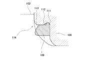
近年では、トラックのリアアクスルに組み込まれて駆動輪を回転自在に支持する車輪用軸受装置では、円すいころ軸受を互いに向き合わせてユニットにした形式の転がり軸受が採用されている。その従来構造の一例として、図7に示すような車輪用軸受装置100が知られている(特許文献1参照)。
この車輪用軸受装置100では、転がり軸受101がアクスルチューブ102の外周に嵌め合わされていて、図示しない車輪を取り付けるためのハブ103が、転がり軸受101の外周に嵌め合わされている。アクスルシャフト104は、アクスルチューブ102と同軸に配置されていて、アクスルシャフト104の一端が図示しないデファレンシャルギアに連結されている。アクスルシャフト104の他端には、径方向に拡がるフランジ105が形成されていて、フランジ105とハブ103とがボルト106で締結されている。こうして、デファレンシャルギアの駆動力が車輪に伝達されている。
In recent years, a rolling bearing of a type in which tapered roller bearings face each other and are united is adopted in a wheel bearing device that is incorporated in a rear axle of a truck and rotatably supports driving wheels. As an example of the conventional structure, a wheel bearing
In the wheel bearing
車両の旋回時には図中に矢印Fで示した向きに、デファレンシャルギアケース内にあるデフオイルが、フランジ105の内側の空間Aに流れてくる。一方、トラックのリアアクスルでは、車両を整備するときに、転がり軸受101をアクスルチューブ102から取り外す必要がある。そのため、転がり軸受101はアクスルチューブ102の外周に径方向のすきまをもって嵌め合わされている。このため、フランジ105の内側に流入したデフオイルが、転がり軸受101とアクスルチューブ102との嵌め合い部のすきまを通って白抜き矢印Gで示した向きに流出する。
従来のリアアクスルでは、デフオイルの流出を防止するため、転がり軸受101の内輪108とアクスルチューブ102の間に図8に示すようなシールリング109が装着されている。シールリング109は、弾性体で形成されており、アクスルチューブ102と内輪108とで軸方向に圧縮することによって、デフオイルの流出を遮断している。
When the vehicle turns, the differential oil in the differential gear case flows into the space A inside the
In the conventional rear axle, a
シールリング109の密封性が不良になると、流出したデフオイルがブレーキロータ107等に付着してブレーキ性能が悪くなるおそれがある。このため、トラックのリアアクスルについては、定期的に分解して点検が行われている。この点検時に、シールリング109は新品と交換される。
If the sealing performance of the
従来のシールリング109は、ニトリルゴムなどのゴム材で形成されている。軽量で、容易に変形するので、シールリング109の組み替え作業は、一般的には手作業で行われている。しかし、シールリング109を組み替える点検作業は、通常、屋内の作業場等で行われ、十分な照明を確保できない場合がある。また、シールリング109の組み付け状態を測定するために、精密な測定装置を設置することも困難である。そのため、シールリング109を正しい位置に装着することが出来たか否かの確認は、もっぱら組み換え作業をする人の手の感覚によって行われている。
上述したように、シールリング109の組み付け状態が不良になると、ブレーキ性能に影響があるため、組み付けにあたっては慎重な作業が要求される。そのため、手で容易に組み付けることが出来るとともに、正しく装着されたことを明確に認識できるシールリング109が要望されていた。
The
As described above, if the assembled state of the
本発明の目的は、リアアクスルの車輪用軸受装置において、シールリングを手作業で組み付けた場合でも、正しく装着されたか否かを手の感覚によって明確に認識することが出来るようにすることである。 An object of the present invention is to make it possible to clearly recognize whether or not a seal ring is correctly mounted by a hand sense in a rear axle wheel bearing device even when the seal ring is manually assembled. .
本発明にかかる車輪用軸受装置の第1の実施形態は、デファレンシャルギアと連結される駆動軸が内挿されたアクスルチューブと、前記アクスルチューブのアウター側端部の外周に形成された段差部に嵌め合わされて、車輪を回転自在に支持する転がり軸受とを備え、前記転がり軸受は、内周に複列の外側軌道面を有する外輪と、外周に前記外側軌道面と径方向に向き合う内側軌道面を有する一対の内輪と、前記外側軌道面と前記内側軌道面との間に配置された複数の転動体を有しており、前記一対の内輪のうち前記段差部と軸方向に衝合する内輪の大端面の内周側に環状段部が形成され、前記環状段部にシールリングが装着された車輪用軸受装置において、前記環状段部では、円筒形状の嵌合面と前記嵌合面より大径の逃げ部とが、前記嵌合面の前記大端面から離れた側でつながっており、前記シールリングでは、弾性体で形成された環状のシール部材と、前記シール部材に沿って略環状で径方向に弾性を有するたわみ部材とが一体に形成されるとともに、前記たわみ部材の外径寸法が、前記嵌合面の内径寸法より大径で、かつ、前記逃げ部の内径寸法より小径であって、前記アクスルチューブに組付けた状態で、前記たわみ部材が前記逃げ部に装着されている。 A wheel bearing device according to a first embodiment of the present invention includes an axle tube in which a drive shaft connected to a differential gear is inserted, and a step portion formed on an outer periphery of an outer side end portion of the axle tube. And a rolling bearing that rotatably supports the wheel, the rolling bearing having an outer ring having a double row outer raceway on an inner circumference, and an inner raceway facing the outer raceway in a radial direction on an outer circumference. A pair of inner rings having a plurality of rolling elements disposed between the outer raceway surface and the inner raceway surface, and an inner ring that abuts the stepped portion of the pair of inner rings in the axial direction. In the wheel bearing device in which an annular step portion is formed on the inner peripheral side of the large end surface, and a seal ring is mounted on the annular step portion, the annular step portion includes a cylindrical fitting surface and a fitting surface . and a flank portion of the large diameter, the fitting The surface is connected on the side remote from the large end face, in the seal ring, and an annular seal member formed of an elastic body, and a flexure member having elasticity radially substantially annular shape along the sealing member A state in which the outer diameter dimension of the flexible member is larger than the inner diameter dimension of the fitting surface and smaller than the inner diameter dimension of the relief portion, and is assembled to the axle tube. The flexible member is attached to the escape portion.
本発明にかかる車輪用軸受装置の第2の実施形態は、デファレンシャルギアと連結される駆動軸が内挿されたアクスルチューブと、前記アクスルチューブのアウター側端部の外周に形成された段差部に嵌め合わされて、車輪を回転自在に支持する転がり軸受とを備え、前記転がり軸受は、内周に複列の外側軌道面を有する外輪と、外周に前記外側軌道面と径方向に向き合う内側軌道面を有する一対の内輪と、前記外側軌道面と前記内側軌道面との間に配置された複数の転動体を有しており、前記一対の内輪のうち前記段差部と軸方向に衝合する内輪の大端面の内周側に環状段部が形成され、前記環状段部にシールリングが装着された車輪用軸受装置において、前記環状段部では、円筒形状の嵌合面と前記嵌合面より大径の逃げ部とが、前記嵌合面の前記大端面から離れた側でつながって形成されており、前記シールリングでは、弾性体で形成された環状のシール部材と、前記シール部材に沿って略環状で径方向に弾性を有するたわみ部材とが一体に形成されており、前記たわみ部材では、前記嵌合面に嵌め合わされる円環部と、前記嵌合面より大径で、かつ、前記逃げ部の内径寸法より小径の切離し部とが一体に形成されており、前記たわみ部材の外周側で、前記円環部と前期切離し部とがつながる位置に切り欠きが形成されており、前記アクスルチューブに組付けた状態で、前記切離し部が前記逃げ部に装着されている。 A wheel bearing device according to a second embodiment of the present invention includes an axle tube in which a drive shaft connected to a differential gear is inserted, and a step portion formed on an outer periphery of an outer side end portion of the axle tube. And a rolling bearing that rotatably supports the wheel, the rolling bearing having an outer ring having a double row outer raceway on an inner circumference, and an inner raceway facing the outer raceway in a radial direction on an outer circumference. A pair of inner rings having a plurality of rolling elements disposed between the outer raceway surface and the inner raceway surface, and an inner ring that abuts the stepped portion of the pair of inner rings in the axial direction. In the wheel bearing device in which an annular step portion is formed on the inner peripheral side of the large end surface, and a seal ring is mounted on the annular step portion, the annular step portion includes a cylindrical fitting surface and a fitting surface . and a flank portion of the large diameter, the fitting It said surface being formed connected at the side remote from the large end face, in the seal ring, the deflection has a sealing annular member formed of an elastic body, the elastic in the radial direction substantially annular shape along the sealing member A member formed integrally, and in the flexible member, an annular portion fitted to the fitting surface, and a separation portion having a diameter larger than that of the fitting surface and smaller than an inner diameter dimension of the escape portion. Are formed integrally, and on the outer peripheral side of the flexible member, a cutout is formed at a position where the annular portion and the previous separation portion are connected to each other, and in the state assembled to the axle tube, the separation The part is attached to the escape part.
本発明によると、リアアクスルの車輪用軸受装置において、シールリングを手作業で組み付けた場合でも、正しく装着されたか否かを手の感覚によって明確に認識することが出来る。 According to the present invention, in the rear axle wheel bearing device, even when the seal ring is manually assembled, it can be clearly recognized by hand feeling whether or not the seal ring is correctly installed.
(第1実施形態)
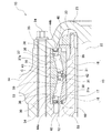
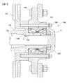
本発明の第1実施形態について、図を参照しつつ説明する。図1は、第1実施形態であるリアアクスルの車輪用軸受装置10において、転がり軸受30が組み込まれている部分を拡大した軸方向断面図である。第1実施形態の車輪用軸受装置10は、転がり軸受30とアクスルチューブ12との間を密封するシールリング60に特徴がある。リアアクスルの構造は、図7に示した従来技術に開示されている構造と同等である。このため、リアアクスルの構造については簡単に説明し、その後、図1によって転がり軸受30について詳細に説明する。
また、以下の説明では、リアアクスルは、図1の右方が車両外側となるので、以下の説明では、図1における右方を「アウター側」、左方を「インナー側」という。
(First embodiment)
A first embodiment of the present invention will be described with reference to the drawings. FIG. 1 is an axial cross-sectional view in which a portion where a rolling bearing 30 is incorporated is enlarged in a rear axle wheel bearing
In the following description, the right side of FIG. 1 is the outer side of the rear axle, and in the following description, the right side in FIG. 1 is referred to as the “outer side” and the left side is referred to as the “inner side”.
図1に示したように、リアアクスルでは、転がり軸受30によって、ハブ14がアクスルチューブ12に対して回転自在に支持されている。
As shown in FIG. 1, in the rear axle, the
アクスルチューブ12は、略円筒形状で、アウター側端部の外周に段差部15が形成されている。段差部15は、軸受装着面16と軸受当接面17とがR面18でつながって形成されている。軸受装着面16は、アクスルチューブ12と同軸の円筒面であり、転がり軸受30の内輪31,31が嵌め合わされる。軸受当接面17は、径方向に形成された面であり、転がり軸受30の軸方向の動きを制限している。
軸受装着面16と転がり軸受30とは、数10μm程度の径方向すきまをもって嵌め合わされている。このため、リアアクスルを定期的に分解点検するときに、転がり軸受30をアクスルチューブ12から容易に取り外すことが出来る。アクスルチューブ12のアウター側の軸端部には雄ねじが形成されている。ナット20を締め付けることによって、転がり軸受30がアクスルチューブ12に固定される。
The
The
アクスルシャフト21は、軸部22とフランジ部23を有する。軸部22は、アクスルチューブ12と同軸に組み込まれている。軸部22のインナー側の軸端は、図示しないデファレンシャルギアに連結されている。フランジ部23は、軸部22のアウター側の軸端に一体に形成されており、径方向外方に延在している。
The axle shaft 21 has a
ハブ14は、転がり軸受30の外輪37の外周に圧入されている。ハブ14とフランジ部23とをボルト24で結合することによって、デファレンシャルギアの動力がハブ14に伝達されている。同時にブレーキロータ25が、ハブ14と締結されている。
The
図1によって、転がり軸受30について説明する。
転がり軸受30は、外輪37と、一対の内輪31,31と、転動体としての複数の円すいころ33と、保持器34,34とを備えている。
The rolling
The rolling
外輪37は、軸受鋼などの鋼材で製作される。外周面37aは、円筒形状である。内周には、複列の外側軌道面36、36が形成されている。外側軌道面36,36は、軸方向に対称に形成されており、それぞれ両軸端に向かうに従って拡径するテーパ面である。
The
一対の内輪31,31は、それぞれ軸受鋼などの鋼材で製作され、互いに同一の形状である。ここでは、インナー側の内輪31について説明し、他の内輪31の説明を省略する。
内輪31の内周面31aは円筒形状である。内周面31aの直径寸法は、アクスルチューブ12の軸受装着面16の外径寸法より50μm程度大きく設定されている。
内輪31の外周には、内側軌道面38が形成されている。内側軌道面38はテーパ面で形成されている。内輪31の軸方向両端は、軸線に直交する面である。内側軌道面38の小径側に形成された面を小端面39、大径側に形成された面を大端面40という。
一対の内輪31,31は、互に小端面39,39が向き合うように組み合わされている。内輪31の内周には、突き合わされた小端面39,39を軸方向に跨いで連結環42が嵌め合わされている。こうして、内輪31,31が軸方向に互いに連結されている。また、内輪31,31の外周には、突き合わされた小端面39、39を軸方向に跨いで、密封部材43が嵌め合わされている。
大端面40の内周側には、環状段部50が形成されている。環状段部50にはシールリング60が組み付けられる。環状段部50の詳細については後述する。
The pair of
The inner
An
The pair of
An
外側軌道面36と内側軌道面38との間には、それぞれ複数の円すいころ33が転動自在に配置されている。複数の円すいころ33は、保持器34によって周方向に所定の間隔で保持されている。外輪37と一対の内輪31,31とで径方向に挟まれた環状空間Cには、グリースが封入されている。環状空間Cの軸方向両側の開口部にはオイルシール44a,44bが装着されていて、外部からの異物の侵入を防止している。また、密封部材43によって、突き合わされた小端面39,39からのグリース流出が防止される。
A plurality of tapered
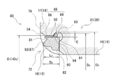
環状段部50と、環状段部50に組み付けられるシールリング60について説明する。
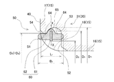
図2は、図1の要部拡大図であって、転がり軸受30が段差部15に組み付けられた状態を示している。
The
FIG. 2 is an enlarged view of a main part of FIG. 1 and shows a state in which the rolling
環状段部50は、大端面40の内周側に形成された環状の凹部である。環状段部50は、嵌合面51と壁面52を有しており、嵌合面51と壁面52との間には逃げ部53が形成されている。環状段部50は、内輪31を熱処理する前に旋削加工によって形成されており、熱処理後に、嵌合面51と壁面52が研磨加工されている。
嵌合面51は、転がり軸受30と同軸の円筒面である。嵌合面51の大端面40側の端部には、面取り54が形成されている。壁面52は、軸と直交する面である。
逃げ部53は、軸方向断面が円弧状である。逃げ部53の径方向の最大寸法D5は、嵌合面51の内径寸法D0より大きい。
The
The
The
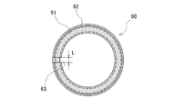
次に、図2と図3によって、シールリング60について説明する。図3は、図2におけるX−Xの位置で、シールリング60を軸と直交する向きに切断したときの断面形状を示している。
Next, the
シールリング60は、たわみ部材61とシール部材62とが一体に形成されている。
In the
たわみ部材61は、金属材料や樹脂材料で形成されている。金属材料として、好ましくはSK材などの炭素工具鋼が使用される。また樹脂材料では、好ましくはグラスファイバーなどで繊維強化されたポリアミド樹脂が使用される。金属材料や樹脂材料は、ここに例示したものに限定されるものではなく、適宜選択することが出来る。
図2に示すように、たわみ部材61の軸方向断面の形状は長方形である。また、図3に示すように、軸に直交する向きの断面では、たわみ部材61は円環状である。円周上の一カ所が切断されており、周方向に所定の大きさですきま63が設けられている。たわみ部材61の外周の直径寸法D1は、嵌合面51の内径寸法D0より大きい。なお、たわみ部材61の軸方向断面の形状は第1実施形態の形状に限定されない。径方向に撓みうる形状であればよく、円形、楕円形など適宜選択できる。
The
As shown in FIG. 2, the shape of the axial cross section of the
シール部材62は、弾性体で形成されている。その材料として、例えば、ニトリルゴムが使用される。材料は、これらに限定されるものではなく、アクリルゴム、フッ素ゴム、その他のゴム材を適宜選択することが出来る。
シール部材62は、金型にゴム材を充填して成形される。成形するときに、あらかじめたわみ部材61が金型に挿入されている。金型に充填した状態で加熱することによって、ゴム材が所定の形状に加硫成形される。また、成形時の熱によってたわみ部材61とシール部材62とが加硫接着されている。こうして、たわみ部材61とシール部材62とが同軸に形成されている。
The
The
図2に示したように、シール部材62は、たわみ部材61の外周を被覆するとともに、たわみ部材61からほぼ等しい長さで軸方向両側に延在している。以下の説明では、たわみ部材61から軸方向両側に伸びるシール部材62の部分を、それぞれ円筒部64という。
各円筒部64,64の外径寸法D4は、嵌合面51の直径寸法D0とほぼ同等である。たわみ部材61の外径寸法D1は嵌合面51の直径寸法D0より大径である。これにより、シールリング60の外周には、全周にわたって径方向に突出した凸部65が形成されている。各円筒部64,64の軸方向端部は、軸方向断面の形状が円弧状である。
各円筒部64,64の内周は、たわみ部材61の内周より大径である。たわみ部材61の径方向内方の端部が、全周にわたってシール部材62の径方向内方に露出している。
こうして、シールリング60は、たわみ部材61を中心にして、軸方向に対称な形状に形成されている。
As shown in FIG. 2, the
The outer diameter dimension D 4 of each
The inner circumference of each
Thus, the
図2に示したように、シールリング60が環状段部50に組み込まれたときには、たわみ部材61が逃げ部53と嵌め合わされている。
第1実施形態では、逃げ部53の内径寸法D5は、たわみ部材61の外径寸法D1より大きい。したがって、たわみ部材61は径方向に拘束されない。また、円筒部64の外径寸法D4が嵌合面51の内径寸法D0とほぼ同等である。このため、シールリング60は、嵌合面51に案内されて環状段部50と同軸に組み込まれている。
As shown in FIG. 2, when the
In the first embodiment, the inner diameter D 5 of the
図2に示したように、シールリング60のインナー側の円筒部64は、R面18と軸方向に接触している。R面18の曲率が大きいときには、円筒部64は軸受当接面17と接触する場合がある。アウター側の円筒部64は、壁面52と軸方向に接触している。シールリング60の軸方向の寸法B1は、R面18と壁面52との軸方向寸法L1より大きい。こうして、シールリング60は、内輪31および段差部15と軸方向にシメシロをもって当接している。
リアアクスルでは、軸部22とアクスルチューブ12との間のすきまを通ってデフオイルがフランジ部23の側の空間Aに流入する(図7参照)。さらに、このデフオイルは、内輪31と軸受装着面16とのすきまを通ってシールリング60に向かって流出する。第1実施形態では、シールリング60が、内輪31と段差部15とのすきまを遮断しているので、デフオイルの流出を防止できる。
なお、アウター側の環状段部50ではデフオイルの流出という不具合が想定できない。このため、シールリング60は、インナー側の環状段部50にのみ組み込まれており、アウター側の環状段部50には組み込まれていない。
As shown in FIG. 2, the inner
In the rear axle, the differential oil flows into the space A on the
In addition, in the outer side
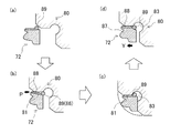
次に、シールリング60を環状段部50に組み付ける手順を説明する。
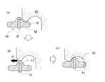
図4は、シールリング60を組み付けるときの、シールリング60と環状段部50との位置関係を表している。図4は、(a)から(c)の順で、組み付け作業が進行している状態を示している。
また、シールリング60の装着作業は、通常、トラックの修理工場等で行われる。このとき、以下の作業は、機械等を使用することなく、もっぱら手作業で行なわれている。
Next, a procedure for assembling the
FIG. 4 shows the positional relationship between the
Also, the mounting operation of the
図4(a)では、シールリング60の一方の円筒部64を、環状段部50の嵌合面51に内篏して、同軸に組み合わせている。円筒部64の外径寸法D4は嵌合面51の内径寸法D0とほぼ同等である。そのため、円筒部64を嵌合面51に容易に挿入することが出来る。
In FIG. 4A, one
たわみ部材61の外径寸法D1は、嵌合面51の内径寸法D0より大きい。このため、図4(b)では、シールリング60を更に環状段部50に押し込んで、嵌合面51の内周に嵌め合わせている。たわみ部材61は、周方向のすきま63(図3参照)を有しているので、径方向内方に容易に撓むことが出来る。
すきま63が小さくなることによってたわみ部材61の直径が縮小する。すきま63が閉じたときのたわみ部材61の直径寸法の変化量ΔDは、すきま63の当初の大きさをL0とした場合には、ΔD=L0/πで求めることが出来る。なお、すきま63が閉じたときの外径寸法をD3としたとき、ΔD=D1−D3である。πは円周率である。
すきま63が閉じたときの外径寸法D3を、嵌合面51の内径寸法D0より小さくなるように設定することによって、組み換え作業をする人は、シールリング60を嵌合面51の内周に容易に押し込むことが出来る。
The outer diameter D 1 of the
As the
By setting the outer diameter D 3 when the
シールリング60が嵌合面51に内篏しているときには、たわみ部材61が弾性をもって径方向に収縮している。この弾性によって、たわみ部材61が元の外径寸法D1に復元しようとするので、シールリング60が嵌合面51に押し付けられている。したがって、シールリング60を軸方向に押し込むときには、シールリング60と嵌合面51との間には、図4(b)に矢印で示す向きのすべり摩擦力Pが生じる。
When the
図4(c)では、たわみ部材61が逃げ部53の位置に到達している。たわみ部材61の外径寸法D1は、逃げ部53の内径寸法D5より小さい。したがって、たわみ部材61は元の外径寸法D1に復元している。このときは、たわみ部材61を径方向内方に付勢する力が作用しないので、すべり摩擦力Pが生じない。
In FIG. 4C, the
すなわち、シールリング60を手作業で環状段部50に挿入する過程において、シールリング60が嵌合面51に内篏しているときには、組み換え作業をする人は、すべり摩擦力Pに応じた力を手に感じている。そして、シールリング60のたわみ部材61が逃げ部53と嵌合した瞬間に、すべり摩擦力Pが軽減したことを感じることが出来る。
こうして、シールリング60を手作業で組み付けた場合に、図4(c)に示すように、たわみ部材61が逃げ部53に装着されたことを、手の感覚によって明確に認識することが出来る。
That is, in the process of manually inserting the
Thus, when the
第1実施形態の効果を明確にするために、比較例として、図8に示した従来構造のシールリング109を組み込むときの状態を説明する。
比較例では、環状段部114の形態は第1実施形態の環状段部50と同等である。比較例においては、逃げ部112に、シールリング109の外周に設けた凸部111を嵌め合わせることによって、シールリング109の抜け止めがされている。シールリング109の凸部111が逃げ部112に嵌め合わされていないときは、シールリング109の姿勢がずれるので密封性能が低下する。
比較例では、シールリング109の全体がゴム材等の弾性体のみで構成されている。ゴム材料のヤング率は0.1GPa程度であり、シールリング109を嵌合面113に嵌め合わせたときに、弾性によって元の外径寸法に復元しようとする力が極めて小さい。このため、シールリング109を軸方向に押し込むときのすべり摩擦力Pが極めて小さい。この結果、シールリング109が逃げ部112に嵌め合わされたとしても、軸方向に押し込むときの力はほとんど変化しない。
こうして、比較例のシールリング109を手作業で環状段部114に組み込む場合には、その組み込み作業をする人にとって、凸部111が逃げ部112に装着されたか否かを認識することが困難である。
In order to clarify the effect of the first embodiment, a state when the
In the comparative example, the form of the
In the comparative example, the
Thus, when the
これに対して、第1実施形態のシールリング60では、たわみ部材61の外周が、嵌合面51の内径寸法D0より大径に設定されている。このため、シールリング60が嵌合面51の内周にはめ込まれたときには、たわみ部材61自体が径方向内方に撓む(図4(b)参照)。たわみ部材61は、金属材料又は樹脂材料で形成されており、そのヤング率は、金属材料の場合は206GPa程度であり、樹脂材料の場合は20〜50GPa程度である。このため、嵌合面51の内周に沿って押し込まれているときのすべり摩擦力Pは、比較例に比べて200〜2000倍程度の大きさになる。
In contrast, in the
この結果、シールリング60が嵌合面51の内周に嵌め合わされている状態から、逃げ部53に嵌め合わされたときには、すべり摩擦力Pが大きく変化する。
第1実施形態の車両用軸受装置では、このすべり摩擦力Pの変化量が大きいことによって、シールリング60を手作業で組み付けた場合でも、図4(c)に示すように、たわみ部材61が確実に逃げ部53に装着されたことを、手の感覚によって明確に認識することが出来る。
As a result, when the
In the vehicular bearing device according to the first embodiment, since the amount of change in the sliding frictional force P is large, even when the
また、第1実施形態のシールリング60は、軸方向に対称な形状である。したがって、環状段部50に嵌め合わせるときに、軸方向のいずれの側を嵌め合わせても、同一の効果を得ることが出来る。したがって、リアアクスルの分解点検時において、シールリング60を交換するときに、シールリング60の向きを確認する必要がない。この結果、誤組込を確実に防止することが出来る。
Further, the
また、第1実施形態のシールリング60では、たわみ部材61の外周をシール部材62で被覆しており、たわみ部材61の内周がシール部材62から露出している。これに対して、たわみ部材61の外周がシール部材62から露出して、たわみ部材61の内周をシール部材62で被覆してもよい。
この場合には、嵌合面51とたわみ部材61とが直接接触するので、たわみ部材61が逃げ部53と嵌合したときに、すべり摩擦力Pの変化を更に明確に把握することが出来る。
In the
In this case, since the
(第2実施形態)
本発明の第2実施形態について、図を参照しつつ説明する。図5は、図2と同様の要部拡大図であって、環状段部80にシールリング72が装着されて、転がり軸受30が段差部15に組み付けられた状態を示している。
第2実施形態は、第1実施形態と比較して、環状段部の逃げ部の形態と、シールリングの形態が異なる。その他の、リアアクスルの構造、及び、転がり軸受30の形態は同等であるので、これらの説明を省略する。なお、第1実施形態と同一の形態については、同一の番号を付して説明する。
(Second Embodiment)
A second embodiment of the present invention will be described with reference to the drawings. FIG. 5 is an enlarged view of a main part similar to FIG. 2, and shows a state in which the
The second embodiment is different from the first embodiment in the form of the relief part of the annular step part and the form of the seal ring. Since the other structures of the rear axle and the form of the rolling
環状段部80は、嵌合面81と壁面82を有しており、嵌合面81と壁面82との間には逃げ部83が形成されている。嵌合面81は、転がり軸受30と同軸の円筒面である。嵌合面81の大端面76側の端部には、面取り54が形成されている。壁面82は、軸と直交する面である。
逃げ部83は、軸方向断面が円弧状である。逃げ部83の径方向の最大寸法D6は、嵌合面81の内径寸法D7より大きい。
The
The
同じく、図5によって、シールリング72について説明する。
Similarly, the
シールリング72は、たわみ部材86とシール部材87とが一体に形成されている。
In the
たわみ部材86は、樹脂材料で形成されている。樹脂材料では、好ましくはグラスファイバーなどで繊維強化されたポリアミド樹脂が使用されるが、これに限定されるものではなく、適宜選択することが出来る。(熱硬化性樹脂の方がよい?)
たわみ部材86は環状であって、円環部88と切離し部89とが一体となっている。円環部88は、円筒形状であって、外径寸法D8は嵌合面81の内径寸法D0と同等である。切離し部89は、円環部88の軸方向の一方の端部に一体に形成されており、軸方向断面の形状が略円形である。その外径寸法D9は、嵌合面81の内径寸法D7より大きく、逃げ部83の径方向の最大寸法D6より小さい。
軸方向断面において、切離し部89と円環部88とは、径方向外方ではV字状の切り欠き90でつながっており、径方向内方では円弧状のつなぎ部91でつながっている。切り欠き90は、円環部88の外周面95が切離し部89の径方向内方に入り込むことによって形成されている。円環部88の外周面95が切離し部89とつながる部分に、切離し部89に向かうにしたがって直径寸法が小さくなる傾斜面92が形成されている。傾斜面92の傾斜角度を適宜選択することによって、円環部88と切離し部89とをつなぐ部分の板厚Cを小さくすることが出来る。これによって、シールリング72を環状段部80から引き抜くときに、切離し部89を容易に切除できる。引き抜き時の状態については後述する。
The
The
In the axial cross section, the separating
シール部材87は、弾性体で形成されている。その材料として、例えば、ニトリルゴムが使用される。材料は、これらに限定されるものではなく、アクリルゴム、フッ素ゴム、その他のゴム材を適宜選択することが出来る。
シール部材87は、金型にゴム材を充填して成形される。成形するときに、あらかじめたわみ部材86が金型に挿入されている。
(シール部材87(ゴム)とたわみ部材86(樹脂)の接合方法は記載していません)
図5に示したように、シール部材87は、たわみ部材86の内周に一体に形成されている。シール部材87には、軸方向の一方に突出する突起93が形成されている。軸方向の他方には、径方向の平面で、ガイド面94が形成されている。
The
The
(The method of joining the seal member 87 (rubber) and the flexible member 86 (resin) is not described.)
As shown in FIG. 5, the
シールリング72が、環状段部80に組み込まれたときには、切離し部89が、逃げ部83と嵌め合う位置に組み込まれている。
逃げ部83の内径寸法D6は、切離し部89の外径寸法D9より大径である。したがって、逃げ部83と切離し部89とが径方向で当接しない。また、円環部88の外径寸法D8は、嵌合面81の内径寸法D7とほぼ同等である。このため、シールリング72は、嵌合面81に案内されて環状段部80と同軸に組み込まれている。
When the
The inner diameter D 6 of the
シールリング72は、ガイド面94が環状段部80の壁面82と当接する向きに組み込まれており、突起93が軸方向のインナー側に突出している。図5では、突起93は、段差部15のR面18と軸方向に接触している。R面18の曲率が大きいときには、軸受当接面17と接触する場合がある。ガイド面94は、環状段部80の壁面82と軸方向に接触している。シール部材87の軸方向の寸法B2は、R面18と壁面82との軸方向寸法L2より大きい。したがって、シール部材87は、内輪73および段差部15と軸方向にシメシロをもって当接している。
こうして、第2実施形態の車輪用軸受装置70では、デフオイルがシールリング72を通り越して外部に流出することがない。なお、第2実施形態においても、シールリング72は、インナー側の環状段部80にのみ組み込まれており、アウター側の環状段部80には組み込まれていない。
The
Thus, in the wheel bearing device 70 according to the second embodiment, the differential oil does not flow outside through the
図6は、シールリング72を組み付けるとき、及び組み付けたシールリング72を取り外すときの、シールリング72と環状段部80との位置関係を表している。図6(a)から図6(c)は、組み付け作業の順にシールリング72の状態を示している。図6(d)は、組み付けられたシールリング72を、軸方向に矢印Yの向きに引き抜くときの状態を示している。
FIG. 6 shows the positional relationship between the
まず、図6(a)から(c)によって、シールリング72を環状段部80に組み付ける手順を説明する。なお、第2実施形態においても、シールリング72装着作業は、すべて手作業で行なわれている。
First, the procedure for assembling the
図6(a)では、切離し部89が環状段部80と向き合うように、シールリング72と環状段部80とが同軸に組み合わされている。
In FIG. 6A, the
図6(b)では、シールリング72を更に環状段部80に押し込んでいる。切離し部89の外径寸法D9は、嵌合面81の内径寸法D7より大きい。たわみ部材86は、樹脂製で、弾性体である。嵌合面81の内周に嵌め合わせたときには、たわみ部材86は、弾性変形して縮径している。この弾性によって、たわみ部材86が元の外径寸法D9に復元しようとする。このため、たわみ部材86が嵌合面81に押し付けられている。したがって、シールリング72を軸方向に押し込むときには、シールリング72と嵌合面81との間に図中に矢印で示した向きのすべり摩擦力Pが生じる。
In FIG. 6B, the
図6(c)では、切離し部89が逃げ部83に到達している。切離し部89の外径寸法D9は、逃げ部83の内径寸法D6より小径である。このため、たわみ部材86を径方向内方に付勢する力が作用しない。したがって、シールリング72にはすべり摩擦力Pが生じない。
In FIG. 6C, the
すなわち、シールリング72を手作業で環状段部80に挿入する過程において、シールリング72が嵌合面81に内篏しているときには、組み付け作業をする人は、すべり摩擦力Pに応じた力を手に感じている。そして、切離し部89が逃げ部83と嵌合した瞬間に、すべり摩擦力Pが軽減したことを感じることが出来る。
こうして、シールリング72を手作業で組み付けた場合に、図6(c)に示すように、切離し部89が逃げ部83に装着されたことを、組み付け作業をする人の手の感覚によって明確に認識することが出来る。
That is, in the process of manually inserting the
Thus, when the
次に、図6(d)によって、シールリング72を環状段部80から取り外す時の手順を説明する。シールリング72を軸方向に矢印Yの向きに移動させたときには、切離し部89が逃げ部83と軸方向に当接する。このとき、切離し部89が、矢印Yと逆向きに付勢される。円環部88と切離し部89とをつなぐ部分の長さC(図5参照)を適宜選択することによって、切離し部89を容易に切除できる。
シールリング72を取り外す時には、円環部88と切離し部89とをつなぐ部分では、円環部88の外周側で引張応力が高くなる。シールリング72では、円環部88の外周側に切り欠き90を形成している(図5参照)ので、応力集中によってさらに高い応力が生じる。このため、円環部88と切離し部89とをつなぐ部分が容易に破断するので、切離し部89を容易に切除できる。この結果、シールリング72では、嵌合面81より大径の部分が切除されるので、環状段部80から容易に取り外すことが出来る。
また、切除された切離し部89は、シール部材87と一体に形成されているので、シールリング72と一体として取り外される。したがって、環状段部80の中に残留しない。
Next, the procedure for removing the
When the
Further, since the cut-off
なお、図6(b)において、切離し部89が径方向内方に付勢された場合には、円環部88の内周側で応力が高くなる。円環部88の内周側では、円環部88と切離し部89が円弧状のつなぎ部91(図5参照)で滑らかにつながっているので応力集中が生じない。したがって、シールリング72を組付けるときであって、切離し部89が径方向内方に縮径した状態のときには、切離し部89が切除されることがない。
In FIG. 6B, when the separating
また、第2実施形態のシールリング72では、たわみ部材86は円環状であって、全周にわたって周方向につながっている。しかし、この形状に限定されない。たとえば、切離し部89の側から円環部88の軸方向中央まで、1以上の径方向のスリットを設けてもよい。これによって、切離し部89を周方向に分離することができる。この場合には、円環部88の板厚を大きくした場合でも、切離し部89を径方向内方に容易に撓ませることが出来る。したがって、シールリング72を、容易に嵌合面81に嵌め合わせることが出来る。
Further, in the
こうして、第2実施形態の車輪用軸受装置70では、シールリング72が嵌合面81の内周に嵌め合わされている状態から、逃げ部83に嵌め合わされたときのすべり摩擦力Pの変化が大きくなる。このすべり摩擦力Pの変化量が大きいことによって、組み付け作業をする人は、切離し部89が逃げ部83に装着されたことを、手の感覚によって明確に認識することが出来る。
さらに、切離し部89を設けたので、車両の定期点検時にシールリング72を交換するときに、古いシールリング72を容易に取り外すことが出来る。このため、定期点検の作業をより効率よく実施できる。
Thus, in the wheel bearing device 70 according to the second embodiment, the change in the sliding frictional force P when the
Furthermore, since the separating
(第1実施形態)
10:車輪用軸受装置、12:アクスルチューブ、14:ハブ、15:段差部、16:軸受装着面、17:軸受当接面、18:R面、21:アクスルシャフト、22:軸部、23:フランジ部、25:ブレーキロータ、30:転がり軸受、31:内輪、33:円すいころ、34:保持器、36:外側軌道面、37:外輪、38:内側軌道面、39:小端面、40:大端面、42:連結環、43:密封部材、50:環状段部、51:嵌合面、52:壁面、53:逃げ部、60:シールリング、61:たわみ部材、62:シール部材、63:すきま、64:円筒部、65:凸部、
(第2実施形態)
70:車輪用軸受装置、72:シールリング、73:内輪、76:大端面、80:環状段部、81:嵌合面、82:壁面、83:逃げ部、86:たわみ部材、87:シール部材、88:円環部、89:切離し部、90:切り欠き、91:つなぎ部、92:傾斜面、93:突起、94:ガイド面、
(従来技術)
100:車輪用軸受装置、101:転がり軸受、102:アクスルチューブ、103:ハブ、104:アクスルシャフト、105:フランジ、106:ボルト、107:ブレーキロータ、108:内輪、109:シールリング、111:凸部、112:逃げ部、113:嵌合面、114:環状段部
(First embodiment)
10: Bearing device for wheels, 12: Axle tube, 14: Hub, 15: Stepped portion, 16: Bearing mounting surface, 17: Bearing contact surface, 18: R surface, 21: Axle shaft, 22: Shaft portion, 23 : Flange portion, 25: brake rotor, 30: rolling bearing, 31: inner ring, 33: tapered roller, 34: cage, 36: outer raceway surface, 37: outer race, 38: inner raceway surface, 39: small end face, 40 : Large end face, 42: connecting ring, 43: sealing member, 50: annular stepped part, 51: fitting surface, 52: wall surface, 53: relief part, 60: seal ring, 61: flexible member, 62: seal member, 63: Clearance, 64: Cylindrical part, 65: Convex part,
(Second Embodiment)
70: bearing device for wheels, 72: seal ring, 73: inner ring, 76: large end surface, 80: annular stepped portion, 81: fitting surface, 82: wall surface, 83: relief portion, 86: flexible member, 87: seal Member, 88: annular part, 89: cut-off part, 90: notch, 91: connecting part, 92: inclined surface, 93: protrusion, 94: guide surface,
(Conventional technology)
DESCRIPTION OF SYMBOLS 100: Bearing apparatus for wheels, 101: Rolling bearing, 102: Axle tube, 103: Hub, 104: Axle shaft, 105: Flange, 106: Bolt, 107: Brake rotor, 108: Inner ring, 109: Seal ring, 111: Convex part, 112: relief part, 113: fitting surface , 114: annular step part
Claims (3)
前記アクスルチューブのアウター側端部の外周に形成された段差部に嵌め合わされて、車輪を回転自在に支持する転がり軸受とを備え、
前記転がり軸受は、内周に複列の外側軌道面を有する外輪と、外周に前記外側軌道面と径方向に向き合う内側軌道面を有する一対の内輪と、前記外側軌道面と前記内側軌道面との間に配置された複数の転動体を有しており、
前記一対の内輪のうち前記段差部と軸方向に衝合する内輪の大端面の内周側に環状段部が形成され、前記環状段部にシールリングが装着された車輪用軸受装置において、
前記環状段部では、円筒形状の嵌合面と前記嵌合面より大径の逃げ部とが、前記嵌合面の前記大端面から離れた側でつながっており、
前記シールリングでは、弾性体で形成された環状のシール部材と、前記シール部材に沿って略環状で径方向に弾性を有するたわみ部材とが一体に形成されるとともに、前記たわみ部材の外径寸法が、前記嵌合面の内径寸法より大径で、かつ、前記逃げ部の内径寸法より小径であって、
前記アクスルチューブに組付けた状態で、前記たわみ部材が前記逃げ部に装着されている車輪用軸受装置。 An axle tube with an inserted drive shaft connected to the differential gear;
A rolling bearing that is fitted to a stepped portion formed on the outer periphery of the outer end portion of the axle tube and rotatably supports the wheel;
The rolling bearing includes an outer ring having a double row outer raceway on the inner circumference, a pair of inner rings having an inner raceway facing the outer raceway in the radial direction on the outer circumference, the outer raceway and the inner raceway, Having a plurality of rolling elements arranged between
In the wheel bearing device in which an annular step portion is formed on the inner peripheral side of the large end surface of the inner ring that abuts the step portion in the axial direction of the pair of inner rings, and a seal ring is attached to the annular step portion.
Wherein in the annular step, a large-diameter escape portion from the mating surface of the cylindrical shape as the fitting surface is provided connected on the side remote from the large end faces of the fitting surface,
In the seal ring, an annular seal member formed of an elastic body and a flexible member that is substantially annular and elastic in the radial direction along the seal member are integrally formed, and the outer diameter dimension of the flexible member Is larger than the inner diameter dimension of the fitting surface, and smaller than the inner diameter dimension of the relief portion,
A wheel bearing device in which the flexible member is attached to the relief portion in a state assembled to the axle tube.
前記アクスルチューブのアウター側端部の外周に形成された段差部に嵌め合わされて、車輪を回転自在に支持する転がり軸受とを備え、
前記転がり軸受は、内周に複列の外側軌道面を有する外輪と、外周に前記外側軌道面と径方向に向き合う内側軌道面を有する一対の内輪と、前記外側軌道面と前記内側軌道面との間に配置された複数の転動体を有しており、
前記一対の内輪のうち前記段差部と軸方向に衝合する内輪の大端面の内周側に環状段部が形成され、前記環状段部にシールリングが装着された車輪用軸受装置において、
前記環状段部では、円筒形状の嵌合面と前記嵌合面より大径の逃げ部とが、前記嵌合面の前記大端面から離れた側でつながって形成されており、
前記シールリングでは、弾性体で形成された環状のシール部材と、前記シール部材に沿って略環状で径方向に弾性を有するたわみ部材とが一体に形成されており、
前記たわみ部材では、前記嵌合面に嵌め合わされる円環部と、前記嵌合面より大径で、かつ、前記逃げ部の内径寸法より小径の切離し部とが一体に形成されており、前記たわみ部材の外周側で、前記円環部と前期切離し部とがつながる位置に切り欠きが形成されており、
前記アクスルチューブに組付けた状態で、前記切離し部が前記逃げ部に装着されている車輪用軸受装置。 An axle tube with an inserted drive shaft connected to the differential gear;
A rolling bearing that is fitted to a stepped portion formed on the outer periphery of the outer end portion of the axle tube and rotatably supports the wheel;
The rolling bearing includes an outer ring having a double row outer raceway on the inner circumference, a pair of inner rings having an inner raceway facing the outer raceway in the radial direction on the outer circumference, the outer raceway and the inner raceway, Having a plurality of rolling elements arranged between
In the wheel bearing device in which an annular step portion is formed on the inner peripheral side of the large end surface of the inner ring that abuts the step portion in the axial direction of the pair of inner rings, and a seal ring is attached to the annular step portion.
Wherein in the annular step, a large-diameter escape portion from the mating surface of the cylindrical shape as the fitting surface is being formed connected on the side remote from the large end faces of the fitting surface,
In the seal ring, an annular seal member formed of an elastic body and a flexible member that is substantially annular and elastic in the radial direction along the seal member are integrally formed.
In the flexible member, an annular portion fitted to the fitting surface, a separation portion having a larger diameter than the fitting surface and a smaller diameter than the inner diameter dimension of the escape portion are integrally formed, On the outer peripheral side of the flexible member, a notch is formed at a position where the annular part and the previous part are connected,
A wheel bearing device in which the separating portion is mounted on the relief portion in a state assembled to the axle tube.
Priority Applications (1)
| Application Number | Priority Date | Filing Date | Title |
|---|---|---|---|
| JP2015140449A JP6617455B2 (en) | 2015-07-14 | 2015-07-14 | Wheel bearing device |
Applications Claiming Priority (1)
| Application Number | Priority Date | Filing Date | Title |
|---|---|---|---|
| JP2015140449A JP6617455B2 (en) | 2015-07-14 | 2015-07-14 | Wheel bearing device |
Publications (2)
| Publication Number | Publication Date |
|---|---|
| JP2017020610A JP2017020610A (en) | 2017-01-26 |
| JP6617455B2 true JP6617455B2 (en) | 2019-12-11 |
Family
ID=57887935
Family Applications (1)
| Application Number | Title | Priority Date | Filing Date |
|---|---|---|---|
| JP2015140449A Active JP6617455B2 (en) | 2015-07-14 | 2015-07-14 | Wheel bearing device |
Country Status (1)
| Country | Link |
|---|---|
| JP (1) | JP6617455B2 (en) |
Family Cites Families (12)
| Publication number | Priority date | Publication date | Assignee | Title |
|---|---|---|---|---|
| US2883224A (en) * | 1955-01-03 | 1959-04-21 | Gen Motors Corp | Fluid seal |
| DE3544988A1 (en) * | 1985-12-19 | 1987-07-02 | Skf Gmbh | SEALED ROLLER BEARING |
| JPH11325089A (en) * | 1998-05-13 | 1999-11-26 | Nippon Seiko Kk | Rolling bearing |
| JP3940304B2 (en) * | 2002-03-07 | 2007-07-04 | 株式会社山田製作所 | Water pump bearing seal device |
| GB2388409B (en) * | 2002-05-10 | 2005-08-31 | Polymer Sealing Solutions Ltd | Seal |
| DE102007020008B4 (en) * | 2007-04-27 | 2024-06-13 | Man Truck & Bus Se | Device for supporting a vehicle wheel, in particular for commercial vehicles |
| JP5252489B2 (en) * | 2008-07-18 | 2013-07-31 | Ntn株式会社 | Drive wheel support device |
| JP2011148409A (en) * | 2010-01-22 | 2011-08-04 | Ntn Corp | Bearing device for wheel |
| JP2011252557A (en) * | 2010-06-03 | 2011-12-15 | Ntn Corp | Rolling bearing |
| JP2011251649A (en) * | 2010-06-03 | 2011-12-15 | Ntn Corp | Bearing device for wheel |
| JP5741108B2 (en) * | 2011-03-22 | 2015-07-01 | 日本精工株式会社 | Rolling bearing |
| JP6235256B2 (en) * | 2013-07-11 | 2017-11-22 | Ntn株式会社 | Wheel bearing device |
-
2015
- 2015-07-14 JP JP2015140449A patent/JP6617455B2/en active Active
Also Published As
| Publication number | Publication date |
|---|---|
| JP2017020610A (en) | 2017-01-26 |
Similar Documents
| Publication | Publication Date | Title |
|---|---|---|
| US8708570B2 (en) | Bearing device for wheel | |
| CN101827715B (en) | Bearing device for wheel | |
| JP4302758B2 (en) | Wheel bearing device | |
| US10086648B2 (en) | Bearing device for a wheel | |
| JP5323337B2 (en) | Wheel bearing device | |
| US8998731B2 (en) | Wheel bearing device | |
| WO2010113842A1 (en) | Annular sealing device | |
| JP6569275B2 (en) | Manufacturing method of wheel bearing device | |
| JP4513295B2 (en) | Method for assembling rolling bearing device | |
| JP2008230487A (en) | Bearing device for driving wheel | |
| JP5323339B2 (en) | Wheel bearing device | |
| JP5236348B2 (en) | Wheel bearing device | |
| CN112400070B (en) | Inserts and wear rings for railway roller bearings | |
| JP6617455B2 (en) | Wheel bearing device | |
| JP2009255729A (en) | Bearing device for wheel | |
| US20080273824A1 (en) | Bearing device for axle and fixing structure using the same | |
| JP6235256B2 (en) | Wheel bearing device | |
| JP5474476B2 (en) | Rolling bearing sealing device and rolling bearing provided with the sealing device | |
| JP6740734B2 (en) | Manufacturing method of bearing device for wheel | |
| JP4943019B2 (en) | Manufacturing method of wheel bearing device | |
| WO2018056000A1 (en) | Bearing device for axle | |
| JP5323338B2 (en) | Wheel bearing device | |
| JP5143442B2 (en) | Drive wheel bearing device | |
| JP2016109162A (en) | Rolling bearing device | |
| JP7602316B2 (en) | Manufacturing method and manufacturing device for wheel bearing device |
Legal Events
| Date | Code | Title | Description |
|---|---|---|---|
| A621 | Written request for application examination |
Free format text: JAPANESE INTERMEDIATE CODE: A621 Effective date: 20180615 |
|
| A977 | Report on retrieval |
Free format text: JAPANESE INTERMEDIATE CODE: A971007 Effective date: 20190515 |
|
| A131 | Notification of reasons for refusal |
Free format text: JAPANESE INTERMEDIATE CODE: A131 Effective date: 20190528 |
|
| A521 | Written amendment |
Free format text: JAPANESE INTERMEDIATE CODE: A523 Effective date: 20190619 |
|
| TRDD | Decision of grant or rejection written | ||
| A01 | Written decision to grant a patent or to grant a registration (utility model) |
Free format text: JAPANESE INTERMEDIATE CODE: A01 Effective date: 20191015 |
|
| A61 | First payment of annual fees (during grant procedure) |
Free format text: JAPANESE INTERMEDIATE CODE: A61 Effective date: 20191028 |
|
| R150 | Certificate of patent or registration of utility model |
Ref document number: 6617455 Country of ref document: JP Free format text: JAPANESE INTERMEDIATE CODE: R150 |