(パチンコ遊技機1の構成等)
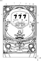
図1は、パチンコ遊技機1の正面図であり、主要部材の配置レイアウトを示す。パチンコ遊技機(遊技機)1は、大別して、遊技盤面を構成する遊技盤(ゲージ盤)2と、遊技盤2を支持固定する遊技機用枠(台枠)3とから構成されている。遊技盤2には、遊技領域が形成され、この遊技領域には、遊技媒体としての遊技球が、所定の打球発射装置から発射されて打ち込まれる。
(Configuration of pachinko machine 1)
FIG. 1 is a front view of a pachinko gaming machine 1 and shows an arrangement layout of main members. The pachinko gaming machine (gaming machine) 1 is roughly composed of a gaming board (gauge board) 2 constituting a gaming board surface and a gaming machine frame (base frame) 3 for supporting and fixing the gaming board 2. A game area is formed on the game board 2, and a game ball as a game medium is launched into a game area from a predetermined hitting device.
遊技盤2の所定位置(図1に示す例では、遊技領域の右側方)には、複数種類の特別識別情報としての特別図柄(特図ともいう。)の可変表示(特図ゲームともいう)を行う、第1特別図柄表示装置4Aと、第2特別図柄表示装置4Bとが設けられている。これらは、7セグメントのLED(light emitting diode)などからなり、特別図柄は、「0」〜「9」を示す数字や「−」などの点灯パターンなどであればよい。特別図柄には、LEDを全て消灯したパターンが含まれてもよい。
In a predetermined position of the game board 2 (in the example shown in FIG. 1, the right side of the game area), a variable display (also called a special figure game) of special symbols (also called special figures) as a plurality of types of special identification information. A first special symbol display device 4A and a second special symbol display device 4B are provided. These consist of 7-segment LEDs (light emitting diodes) and the like, and special symbols may be numbers such as “0” to “9” or lighting patterns such as “−”. The special symbol may include a pattern in which all LEDs are turned off.
なお、特別図柄の「可変表示」とは、例えば、複数種類の特別図柄を更新表示などにより変動させる(変動可能に表示する)ことである(後述の他の図柄の可変表示についても同じ)。可変表示の最後には、表示結果(可変表示結果)として所定の特別図柄が停止表示(導出表示などともいう)される(後述の他の可変表示についても同じ)。なお、図柄(特に、後述の飾り図柄)の変動として、スクロール表示、変形、拡大/縮小などが行われてもよい。
Note that “variable display” of special symbols means, for example, that a plurality of types of special symbols are changed (displayed in a variable manner) by update display or the like (the same applies to variable display of other symbols described later). At the end of the variable display, a predetermined special symbol is stopped as a display result (variable display result) (also referred to as a derivation display) (the same applies to other variable displays described later). Note that scroll display, deformation, enlargement / reduction, and the like may be performed as variations in symbols (in particular, decorative symbols described later).
なお、以下では、第1特別図柄表示装置4Aにおいて可変表示される特別図柄を「第1特図」ともいい、第2特別図柄表示装置4Bにおいて可変表示される特別図柄を「第2特図」ともいう。また、第1特図を用いた特図ゲームを「第1特図ゲーム」といい、第2特図を用いた特図ゲームを「第2特図ゲーム」ともいう。
In the following, the special symbol variably displayed on the first special symbol display device 4A is also referred to as "first special symbol", and the special symbol variably displayed on the second special symbol display device 4B is "second special symbol". Also called. In addition, the special figure game using the first special figure is referred to as a “first special figure game”, and the special figure game using the second special figure is also referred to as a “second special figure game”.
遊技盤2における遊技領域の中央付近には画像表示装置5が設けられている。画像表示装置5は、例えばLCD(液晶表示装置)等から構成され、各種の演出画像を表示する表示領域を形成している。
An image display device 5 is provided near the center of the game area on the game board 2. The image display device 5 is composed of, for example, an LCD (liquid crystal display device) or the like, and forms a display area for displaying various effect images.
画像表示装置5の画面上では、第1特図ゲームや第2特図ゲームと同期して、特別図柄とは異なる複数種類の装飾識別情報としての飾り図柄(数字などを示す図柄など)の可変表示が行われる。一例として、画像表示装置5の画面上では、第1特図ゲーム又は第2特図ゲームに同期して、「左」、「中」、「右」の各飾り図柄表示エリア5L、5C、5Rにおいて飾り図柄の可変表示(例えば上下方向のスクロール表示や更新表示)が行われる。
On the screen of the image display device 5, in synchronization with the first special symbol game or the second special symbol game, a plurality of types of decorative symbols (such as symbols indicating numerals) that are different from the special symbols can be changed. Display is performed. As an example, on the screen of the image display device 5, the “left”, “middle”, and “right” decorative symbol display areas 5L, 5C, and 5R are synchronized with the first special game or the second special game. , Variable display of decorative symbols (for example, vertical scroll display or update display) is performed.
画像表示装置5の画面上には、表示エリア5Hも配置されている。表示エリア5Hには、実行が保留されている第1特図ゲーム(飾り図柄の可変表示)に対応する第1保留表示画像(ここでは、丸の画像)が右詰めで表示され、実行が保留されている第2特図ゲーム(飾り図柄の可変表示)に対応する第2保留表示画像(ここでは、丸の画像)が左詰めで表示される。
On the screen of the image display device 5, a display area 5H is also arranged. In the display area 5H, a first hold display image (here, a circle image) corresponding to the first special figure game (variable display of decorative symbols) for which execution is suspended is displayed right-justified and execution is suspended. A second reserved display image (here, a circle image) corresponding to the second special figure game (variable display of decorative symbols) being displayed is displayed left-justified.
なお、特図ゲームの保留数は、特図保留記憶数ともいう。特に、第1特図ゲームの保留数を、第1特図保留記憶数という。第2特図ゲームの保留数を、第2特図保留記憶数という。第1保留表示画像の数により、第1特図保留記憶数が示され、第2保留表示画像の数により、第2特図保留記憶数が示される。第1保留表示画像及び第2保留表示画像を総称して、総称して保留表示画像ということがある。
Note that the number of special figure games held is also referred to as a special figure holding memory number. In particular, the number of holds of the first special figure game is referred to as a first special figure hold memory number. The number of holds of the second special figure game is referred to as the second special figure hold memory number. The number of first reserved display images indicates the first special figure reserved memory number, and the number of second reserved display images indicates the second special figure reserved memory number. The first hold display image and the second hold display image may be collectively referred to as a hold display image.
また、特図保留記憶数を特定可能に表示するための第1保留表示器25Aと第2保留表示器25Bとが設けられている。第1保留表示器25Aと第2保留表示器25Bとはそれぞれ、複数のLEDを含んで構成され、LEDの点灯個数によって、第1特図保留記憶数と第2特図保留記憶数とを表示する。
In addition, a first hold indicator 25A and a second hold indicator 25B are provided for displaying the special figure hold memory number in an identifiable manner. Each of the first hold indicator 25A and the second hold indicator 25B includes a plurality of LEDs, and displays the first special figure reserved memory number and the second special figure reserved memory number depending on the number of LEDs lit. To do.
画像表示装置5の下方には、普通入賞球装置6Aと、普通可変入賞球装置6Bとが設けられている。
Below the image display device 5, an ordinary winning ball device 6A and an ordinary variable winning ball device 6B are provided.
普通入賞球装置6Aは、例えば所定の玉受部材によって常に遊技球が進入可能な一定の開放状態に保たれる第1始動入賞口を形成する。第1始動入賞口に遊技球が進入したときには、第1始動口スイッチ22A(図2参照)がオンし、これによって、当該遊技球の進入が検出される(このときには、所定個(例えば3個)の賞球が払い出されるとともに、第1特図ゲームが開始され得る。)。
The normal winning ball device 6A forms a first start winning opening that is maintained in a certain open state in which a game ball can always enter by a predetermined ball receiving member, for example. When a game ball enters the first start winning opening, the first start port switch 22A (see FIG. 2) is turned on, thereby detecting the entry of the game ball (at this time, a predetermined number (for example, three) ) And the first special figure game can be started.)
普通可変入賞球装置6Bは、普通電動役物用のソレノイド81(図2参照)によって垂直位置となる閉鎖状態と傾動位置となる開放状態とに変化する一対の可動翼片を有する電動チューリップ型役物(普通電動役物)を備え、第2始動入賞口を形成する。普通可変入賞球装置6Bは、例えば、ソレノイド81がオフ状態であるときに可動翼片が垂直位置となることにより、当該可動翼片の先端が普通入賞球装置6Aに近接し、第2始動入賞口に遊技球が進入しない閉鎖状態になる(第2始動入賞口が閉鎖状態になるともいう。)。その一方で、普通可変入賞球装置6Bは、ソレノイド81がオン状態であるときに可動翼片が傾動位置となることにより、第2始動入賞口に遊技球が進入できる開放状態になる(第2始動入賞口が開放状態になるともいう。)。第2始動入賞口に遊技球が進入したときには、第2始動口スイッチ22B(図2参照)がオンし、これによって、当該遊技球の進入が検出される(このときには、所定個(例えば3個)の賞球が払い出されるとともに、第2特図ゲームが開始され得る。)。
The normally variable winning ball apparatus 6B is an electric tulip type hand having a pair of movable wing pieces that are changed between a closed state in a vertical position and an open state in a tilted position by a solenoid 81 (see FIG. 2) for a normal electric accessory. The object (ordinary electric accessory) is provided, and the second start winning opening is formed. In the normal variable winning ball device 6B, for example, when the solenoid 81 is in the OFF state, the movable wing piece is in the vertical position, so that the tip of the movable wing piece comes close to the normal winning ball device 6A, and the second start winning prize is obtained. The game ball enters a closed state where the game ball does not enter the mouth (the second start winning port is also referred to as a closed state). On the other hand, the normally variable winning ball apparatus 6B is in an open state in which the game ball can enter the second start winning opening by moving the movable wing piece to the tilted position when the solenoid 81 is in the on state (second ball). It is also said that the start winning opening is opened.) When a game ball enters the second start winning opening, the second start port switch 22B (see FIG. 2) is turned on, thereby detecting the entry of the game ball (at this time, a predetermined number (for example, three) ) And the second special figure game can be started.
普通入賞球装置6Aと普通可変入賞球装置6Bの下方には、特別可変入賞球装置7が設けられている。特別可変入賞球装置7は、大入賞口扉用となるソレノイド82(図2参照)によって開閉駆動される大入賞口扉を備え、その大入賞口扉によって開放状態と閉鎖状態とに変化する特定領域としての大入賞口を形成する。
A special variable winning ball device 7 is provided below the normal winning ball device 6A and the normal variable winning ball device 6B. The special variable winning ball apparatus 7 includes a large winning opening door that is opened and closed by a solenoid 82 (see FIG. 2) that is used for the large winning opening door. Form a big prize opening as an area.
一例として、特別可変入賞球装置7では、大入賞口扉用のソレノイド82がオフ状態であるときに大入賞口扉が大入賞口を閉鎖状態として、遊技球が大入賞口に進入(例えば、通過)できなくなる。その一方で、特別可変入賞球装置7では、大入賞口扉用のソレノイド82がオン状態であるときに大入賞口扉が大入賞口を開放状態として、遊技球が大入賞口に進入しやすくなる。
As an example, in the special variable winning ball apparatus 7, when the solenoid 82 for the big prize opening door is in the off state, the big winning opening door closes the big winning opening and the game ball enters the big winning opening (for example, Cannot pass). On the other hand, in the special variable winning ball apparatus 7, when the solenoid 82 for the special prize opening door is in the ON state, the special prize opening door opens the big prize opening, so that the game ball can easily enter the special prize opening. Become.
大入賞口に遊技球が進入したときには、カウントスイッチ23(図2参照)がオンし、これによって、当該遊技球の進入が検出される。このときには、所定個数(例えば14個)の遊技球が賞球として払い出される。こうして、大入賞口に遊技球が進入したときには、例えば第1始動入賞口や第2始動入賞口に遊技球が進入したときよりも多くの賞球が払い出される。
When a game ball enters the big prize opening, the count switch 23 (see FIG. 2) is turned on, and thereby the entry of the game ball is detected. At this time, a predetermined number (for example, 14) of game balls are paid out as prize balls. In this way, when game balls enter the grand prize winning opening, for example, more prize balls are paid out than when game balls enter the first start winning opening or the second start winning opening.
遊技盤2の所定位置(図1に示す例では、遊技領域の左側方)には、普通図柄表示器20が設けられている。一例として、普通図柄表示器20は、7セグメントのLEDなどからなり、特別図柄とは異なる複数種類の普通識別情報としての普通図柄(「普図」あるいは「普通図」ともいう)の可変表示を行う。このような普通図柄の可変表示は、普図ゲーム(「普通図ゲーム」ともいう)ともいう。
A normal symbol display 20 is provided at a predetermined position of the game board 2 (on the left side of the game area in the example shown in FIG. 1). As an example, the normal symbol display 20 is made up of 7-segment LEDs and the like, and can display variable symbols of ordinary symbols (also called “ordinary symbols” or “ordinary symbols”) as a plurality of types of ordinary identification information different from the special symbols. Do. Such variable display of normal symbols is also referred to as a general game (also referred to as a “normal game”).
普図ゲームは、遊技球が通過ゲート41を通過したことに基づいて実行される。遊技球が通過ゲート41を通過したときには、図2のゲートスイッチ21がオンになり、これにより当該遊技球の通過が検出される。
The usual game is executed based on the fact that the game ball has passed through the passage gate 41. When the game ball passes through the passage gate 41, the gate switch 21 of FIG. 2 is turned on, and thereby the passage of the game ball is detected.
普通図柄表示器20の上方には、普図保留表示器25Cが設けられている。普図保留表示器25Cは、例えば4個のLEDを含んで構成され、実行が保留されている普図ゲームの数である普図保留記憶数をLEDの点灯個数により表示する。
Above the normal symbol display 20, a universal figure holding display 25 </ b> C is provided. The general figure hold display unit 25C is configured to include, for example, four LEDs, and displays the number of general figure hold storage, which is the number of general figure games that are being executed, by the number of lighted LEDs.
遊技盤2の表面には、上記の構成以外にも、遊技球の流下方向や速度を変化させる風車及び多数の障害釘が設けられている。遊技領域の最下方には、いずれの入賞口にも進入しなかった遊技球が取り込まれるアウト口が設けられている。
In addition to the above-described configuration, the surface of the game board 2 is provided with a windmill for changing the flow direction and speed of the game ball and a number of obstacle nails. In the lowermost part of the game area, there is provided an out port through which game balls that have not entered any winning port are taken.
遊技機用枠3の左右上部位置には、効果音等を再生出力するためのスピーカ8L、8Rが設けられており、さらに遊技領域周辺部には、遊技効果用の遊技効果ランプ9が設けられている。遊技効果ランプ9は、LEDを含んで構成されている。
Speakers 8L and 8R for reproducing and outputting sound effects and the like are provided at the left and right upper positions of the gaming machine frame 3, and a game effect lamp 9 for game effects is provided at the periphery of the game area. ing. The game effect lamp 9 includes an LED.
遊技機用枠3の右下部位置には、遊技媒体としての遊技球を打球発射装置により遊技領域に向けて発射するために遊技者等によって操作される打球操作ハンドル(操作ノブ)が設けられている。
In the lower right position of the gaming machine frame 3, a hitting operation handle (operation knob) operated by a player or the like for launching a game ball as a game medium toward a game area by a hitting ball launching device is provided. Yes.
遊技領域の下方における遊技機用枠3の所定位置には、賞球として払い出された遊技球や所定の球貸機により貸し出された遊技球を、打球発射装置へと供給可能に保持(貯留)する上皿(打球供給皿)が設けられている。遊技機用枠3の下部には、上皿から溢れた余剰球などを、パチンコ遊技機1の外部へと排出可能に保持(貯留)する下皿が設けられている。
At a predetermined position of the gaming machine frame 3 below the gaming area, a game ball paid out as a prize ball or a game ball lent out by a predetermined ball lending machine is held (stored) so as to be supplied to a ball hitting device. )) Is provided. Below the gaming machine frame 3, there is provided a lower plate that holds (stores) surplus balls overflowing from the upper plate so as to be discharged to the outside of the pachinko gaming machine 1.
画像表示装置5の下方には、演出装置200が配置されている。演出装置200は、識別情報の可変表示等の各種演出画像に合わせてあるいは独立して動作することで、演出を実行できる。
A rendering device 200 is disposed below the image display device 5. The effect device 200 can execute an effect by operating in accordance with various effect images such as variable display of identification information or independently.
パチンコ遊技機1には、例えば図2に示すような主基板11、演出制御基板12、音声制御基板13、ランプ制御基板14、中継基板15などが搭載されている。
In the pachinko gaming machine 1, for example, a main board 11, an effect control board 12, an audio control board 13, a lamp control board 14, and a relay board 15 as shown in FIG. 2 are mounted.
主基板11は、メイン側の制御基板であり、パチンコ遊技機1における遊技の進行(特図ゲームや普図ゲームの実行、各種始動入賞や各種保留記憶の管理、大当り抽選や普図当り抽選の実行、大当り遊技状態の制御、演出制御基板12への演出制御コマンドの送信など)を制御する機能、演出制御基板12に向けて演出制御コマンドを送信する機能を有する。主基板11は、遊技制御用マイクロコンピュータ100、スイッチ回路110、ソレノイド回路111などを有する。
The main board 11 is a control board on the main side, and the progress of the game in the pachinko gaming machine 1 (execution of special figure games and ordinary figure games, management of various starting prizes and various holding memories, lottery lottery and lottery per usual figure Execution, control of a big hit gaming state, transmission of an effect control command to the effect control board 12, and the like, and a function of transmitting an effect control command to the effect control board 12. The main board 11 includes a game control microcomputer 100, a switch circuit 110, a solenoid circuit 111, and the like.
主基板11に搭載された遊技制御用マイクロコンピュータ100は、例えば1チップのマイクロコンピュータであり、ROM(Read Only Memory)101と、RAM(Random Access Memory)102と、CPU(Central Processing Unit)103と、乱数回路104と、I/O(Input/Output port)105とを備える。
The game control microcomputer 100 mounted on the main board 11 is, for example, a one-chip microcomputer, which includes a ROM (Read Only Memory) 101, a RAM (Random Access Memory) 102, a CPU (Central Processing Unit) 103, and the like. And a random number circuit 104 and an I / O (Input / Output port) 105.
一例として、CPU103がROM101に記憶されたプログラムを実行することにより、主基板11の機能(遊技の進行の制御)を実現する。このとき、ROM101が記憶する各種データ(変動パターン、演出制御コマンド、各種テーブルなどのデータ)が用いられ、RAM102がメインメモリとして使用される。
As an example, the CPU 103 executes a program stored in the ROM 101 to realize the function of the main board 11 (control of the progress of the game). At this time, various data (data such as variation patterns, presentation control commands, various tables) stored in the ROM 101 are used, and the RAM 102 is used as a main memory.
乱数回路104は、遊技の進行を制御するときに使用される各種の乱数値(遊技用乱数)を示す数値データを更新可能にカウントする。遊技用乱数は、CPU103が所定のコンピュータプログラムを実行することで更新されるもの(ソフトウェアで更新されるもの)であってもよい。
The random number circuit 104 counts numerical data indicating various random number values (game random numbers) used for controlling the progress of the game in an updatable manner. The game random number may be updated by CPU 103 executing a predetermined computer program (updated by software).
I/O105は、例えば各種信号が入力される入力ポートと、各種信号を伝送するための出力ポートとを含んで構成される。
The I / O 105 includes, for example, an input port to which various signals are input and an output port for transmitting various signals.
CPU103は、I/O105を介して、第1特別図柄表示装置4A、第2特別図柄表示装置4B、普通図柄表示器20、第1保留表示器25A、第2保留表示器25B、普図保留表示器25Cなどを制御(駆動)する信号を出力し、これらを制御する。
The CPU 103, via the I / O 105, displays the first special symbol display device 4A, the second special symbol display device 4B, the normal symbol display device 20, the first hold display device 25A, the second hold display device 25B, and the general drawing hold display. A signal for controlling (driving) the device 25C and the like is output and controlled.
スイッチ回路110は、遊技球検出用の各種スイッチ(ゲートスイッチ21、始動口スイッチ(第1始動口スイッチ22Aおよび第2始動口スイッチ22B)、カウントスイッチ23)からの検出信号(遊技媒体が通過又は進入してスイッチがオンになったことを示す検出信号など)を取り込んで遊技制御用マイクロコンピュータ100に伝送する。
The switch circuit 110 is configured to detect detection signals (game media pass or not) from various switches for detecting a game ball (gate switch 21, start port switch (first start port switch 22A and second start port switch 22B), count switch 23). A detection signal indicating that the switch has entered and the switch is turned on is taken in and transmitted to the game control microcomputer 100.
ソレノイド回路111は、遊技制御用マイクロコンピュータ100からのソレノイド駆動信号(例えば、ソレノイド81やソレノイド82をオンする信号など)を、普通電動役物用のソレノイド81や大入賞口扉用のソレノイド82に伝送する。
The solenoid circuit 111 sends a solenoid drive signal (for example, a signal for turning on the solenoid 81 or the solenoid 82) from the game control microcomputer 100 to the solenoid 81 for the ordinary electric accessory or the solenoid 82 for the grand prize opening door. To transmit.
主基板11(遊技制御用マイクロコンピュータ100)から演出制御基板12に向けて伝送される演出制御コマンドは、中継基板15によって中継される。
The effect control command transmitted from the main board 11 (game control microcomputer 100) to the effect control board 12 is relayed by the relay board 15.
演出制御基板12は、主基板11とは独立したサブ側の制御基板であり、中継基板15を介して主基板11から伝送された演出制御コマンドを受信し、受信した演出制御コマンドに基づいて各種の演出(飾り図柄の可変表示、演出装置を含む。)を実行する機能を有する。
The effect control board 12 is a sub-side control board independent of the main board 11, receives the effect control command transmitted from the main board 11 via the relay board 15, and performs various operations based on the received effect control command. Has a function of executing the effect (including variable display of decorative symbols and effect device).
演出制御基板12には、演出制御用CPU120と、ROM121と、RAM122と、表示制御部123と、乱数回路124と、I/O125とが搭載されている。
On the effect control board 12, an effect control CPU 120, a ROM 121, a RAM 122, a display control unit 123, a random number circuit 124, and an I / O 125 are mounted.
一例として、演出制御用CPU120がROM121に記憶されたプログラムを実行することにより、演出制御基板12の機能(演出の実行)を実現する。このとき、ROM121が記憶する各種データ(演出制御パターンに用いるデータや各種テーブルなどのデータ)が用いられ、RAM122がメインメモリとして使用される。
For example, the effect control CPU 120 executes the program stored in the ROM 121, thereby realizing the function of the effect control board 12 (execution of the effect). At this time, various data stored in the ROM 121 (data used for the effect control pattern and data such as various tables) are used, and the RAM 122 is used as the main memory.
表示制御部123は、演出制御用CPU120からの表示制御指令に基づき、画像表示装置5において表示する演出画像の映像信号を出力し、画像表示装置5に演出画像を表示する。一例として、表示制御部123には、VDP(Video Display Processor)、CGROM(Character Generator ROM)、VRAM(Video RAM)などが搭載されていればよい。
The display control unit 123 outputs a video signal of the effect image displayed on the image display device 5 based on the display control command from the effect control CPU 120, and displays the effect image on the image display device 5. As an example, the display control unit 123 may be equipped with a VDP (Video Display Processor), a CGROM (Character Generator ROM), a VRAM (Video RAM), or the like.
乱数回路124は、演出動作を制御するときに使用される各種の乱数値(演出用乱数)を示す数値データを更新可能にカウントする。演出用乱数は、演出制御用CPU120が所定のコンピュータプログラムを実行することで更新されるもの(ソフトウェアで更新されるもの)であってもよい。
The random number circuit 124 counts numerical data indicating various random numbers (rendering random numbers) used for controlling the rendering operation in an updatable manner. The effect random number may be updated (updated by software) when the effect control CPU 120 executes a predetermined computer program.
演出制御基板12に搭載されたI/O125は、例えば主基板11などから伝送された演出制御コマンドを取り込むための入力ポートと、各種信号を伝送するための出力ポートとを含んで構成される。
The I / O 125 mounted on the effect control board 12 includes, for example, an input port for taking in an effect control command transmitted from the main board 11 and the like, and an output port for transmitting various signals.
音声制御基板13は、演出制御基板12からの効果音信号に基づき、スピーカ8L、8Rから音声(効果音信号が指定する音声)を出力させる機能を有する。
The sound control board 13 has a function of outputting sound (sound designated by the sound effect signal) from the speakers 8L and 8R based on the sound effect signal from the effect control board 12.
ランプ制御基板14は、演出制御基板12からの電飾信号に基づき、遊技効果ランプ9の点灯/消灯駆動(電飾信号が示す駆動内容による点灯/消灯)を行う機能を有する。
The lamp control board 14 has a function of turning on / off the game effect lamp 9 (turning on / off according to the drive content indicated by the electrical decoration signal) based on the electrical decoration signal from the effect control board 12.
画像表示装置5は、液晶パネル、ELパネルなどからなる表示パネルと、当該表示パネルを駆動するドライバ回路などを備える。表示制御部123からI/O125を介して画像表示装置5に供給された映像信号は、前記ドライバ回路に入力される。ドライバ回路は、当該映像信号が表す画像を表示パネルに表示させる。これによって、画像表示装置5には、各種の演出画像などが表示されることになる。
The image display device 5 includes a display panel including a liquid crystal panel, an EL panel, and a driver circuit that drives the display panel. The video signal supplied from the display control unit 123 to the image display device 5 via the I / O 125 is input to the driver circuit. The driver circuit displays an image represented by the video signal on the display panel. As a result, various effect images and the like are displayed on the image display device 5.
演出装置200は、駆動機構210と、可動体250を備え、これらは、演出制御基板12との信号(後述の制御信号や検出信号など)のやりとりにより、演出制御基板12(演出制御CPU120)により制御される。
The stage device 200 includes a drive mechanism 210 and a movable body 250, which are exchanged by the stage control board 12 (stage control CPU 120) by exchanging signals (such as control signals and detection signals described later) with the stage control board 12. Be controlled.
(遊技の進行や演出の進行など)
パチンコ遊技機1が備える打球操作ハンドルへの遊技者による回転操作により、遊技媒体(遊技球)が遊技領域に向けて発射される。
(Progress of games, progress of production, etc.)
A game medium (game ball) is launched toward the game area by a rotation operation by the player to the hitting operation handle provided in the pachinko gaming machine 1.
(主基板11で制御される遊技の進行)
遊技領域を流下した遊技球が通過ゲート41を通過したときには、普図ゲーム(普通図柄の可変表示)が開始される。なお、すでに他の普図ゲームが実行されている、下記の開放制御中など、普図ゲームを開始できないとき(開始条件が成立していないとき)には、4つなどを上限として普図ゲームの実行は保留される。保留された普図ゲームは、当該普図ゲームを開始できる開始条件の成立(他の普図ゲームが実行されておらず、開放制御中でもないなど)により実行される。普図保留記憶数が上限値に達しているときに遊技球が通過ゲート41を通過したときには、当該普図保留記憶数は増えないで、当該通過は無効化される。
(Progress of games controlled by main board 11)
When the game ball that has flowed down the game area passes through the passing gate 41, a normal game (variable display of normal symbols) is started. In addition, when another general game is already running, or when the normal game cannot be started (such as when the start condition is not satisfied), such as during the following opening control, the maximum number of games is limited to 4 Execution is deferred. The held ordinary game is executed when a start condition for starting the ordinary game is satisfied (for example, no other ordinary game is being executed and no release control is being performed). If the game ball passes through the passing gate 41 when the number of reserved maps has reached the upper limit, the number of stored maps is not increased and the passing is invalidated.
普図ゲームで停止表示される可変表示結果には、普図当り図柄(例えば、「7」などの普図)と、普図ハズレ図柄(例えば、「−」などの普図)と、がある。普図当り図柄が停止表示(導出)されるときは、可変表示結果が「普図当り」のときである。普図ハズレ図柄が停止表示(導出)されるときは、可変表示結果が「普図ハズレ」のときである。
The variable display results that are stopped and displayed in the ordinary game include a symbol per symbol (for example, a common symbol such as “7”) and a common symbol losing symbol (for example, a common symbol such as “−”). . When the symbol per symbol is stopped (derived), the variable display result is “per symbol”. The case where the usual figure losing symbol is stopped (derived) is when the variable display result is “general figure losing”.
「普図当り」のときには、普通可変入賞球装置6Bの可動翼片を所定期間傾動位置とする開放制御(第2始動入賞口が開放状態になる。)が行われる。「普図ハズレ」のときには、前記開放制御は行われない。
In the case of “per normal”, an opening control (the second start winning opening is opened) is performed in which the movable blade piece of the normal variable winning ball apparatus 6B is tilted for a predetermined period. The opening control is not performed in the case of “ordinary loss”.
遊技領域を流下した遊技球が、普通入賞球装置6Aに形成された第1始動入賞口に進入したときには、第1特図ゲームが開始される。また、遊技球が、普通可変入賞球装置6Bに形成された第2始動入賞口に進入したときには、第2特図ゲームが開始される。なお、すでに他の特図ゲームが実行中である、後述の大当り遊技状態に制御されているときなど、特図ゲームを開始できないとき(開始条件が成立していないとき)には、それぞれ4つなどを上限として特図ゲームの実行は保留される。保留された特図ゲームは、特図ゲームを開始できる開始条件の成立(他の特図ゲームが実行されておらず、大当り遊技状態中でもないなど)により実行される。
When the game ball flowing down the game area enters the first start winning opening formed in the normal winning ball apparatus 6A, the first special game is started. Further, when the game ball enters the second start winning opening formed in the normal variable winning ball apparatus 6B, the second special game is started. When the special figure game cannot be started (when the start condition is not satisfied), such as when another special figure game is already being executed or the game is controlled to the big hit game state described later, each of the four special figure games is four. Execution of the special figure game is suspended with the above as an upper limit. The reserved special figure game is executed when a start condition capable of starting the special figure game is satisfied (other special figure games are not executed and are not in the big hit gaming state, etc.).
第1特図保留記憶数が上限値に達しているときに遊技球が第1始動入賞口を進入したときには、当該第1特図保留記憶数は増えないで、当該進入は無効化される(賞球はあってもよい)。第2特図保留記憶数が上限値に達しているときに遊技球が第2始動入賞口を進入したときには、当該第2特図保留記憶数は増えないで、当該進入は無効化される(賞球はあってもよい)。
When the game ball enters the first start winning opening when the first special figure reserved memory number reaches the upper limit value, the first special figure reserved memory number does not increase and the entry is invalidated ( There may be a prize ball). When the game ball enters the second start winning opening when the second special figure reserved memory number reaches the upper limit value, the second special figure reserved memory number does not increase and the entry is invalidated ( There may be a prize ball).
第1特図保留記憶数を増やす遊技球の第1始動入賞口への進入(入賞)を第1始動入賞ともいう。第2特図保留記憶数を増やす遊技球の第2始動入賞口への進入(入賞)を第2始動入賞ともいう。これら入賞を総称して単に始動入賞ともいう。
The entry (winning) of a game ball that increases the number of first special figure reserved memories into the first starting winning opening is also referred to as a first starting winning. The entry (winning) of the game ball that increases the second special figure reserved memory number into the second starting winning opening is also referred to as a second starting winning. These winnings are collectively referred to simply as starting winnings.
特図ゲームで停止表示される可変表示結果には、大当り図柄(例えば、「3」、「7」などの特図)と、ハズレ図柄(例えば、「−」などの特図)と、がある。大当り図柄が停止表示(導出)されるときは、可変表示結果が「大当り」のときである。ハズレ図柄が停止表示(導出)されるときは、可変表示結果が「ハズレ」のときである。
The variable display results stopped and displayed in the special figure game include a jackpot symbol (for example, a special symbol such as “3” and “7”) and a lost symbol (for example, a special symbol such as “−”). . When the jackpot symbol is stopped (displayed), the variable display result is “big jackpot”. The lost symbol is stopped (derived) when the variable display result is “lost”.
第1特図ゲーム又は第2特図ゲームの可変表示結果が「大当り」(特定表示結果)のときには、遊技者にとって有利な有利状態としての大当り遊技状態に制御される。可変表示結果が「ハズレ」のときには、大当り遊技状態には制御されない。
When the variable display result of the first special figure game or the second special figure game is “big hit” (specific display result), the big hit gaming state is controlled as an advantageous state advantageous to the player. When the variable display result is “losing”, it is not controlled to the big hit gaming state.
大当り遊技状態では、特別可変入賞球装置7により形成される大入賞口が開放状態となる。当該開放状態は、所定期間(例えば29秒間)の経過タイミングと、大入賞口に進入した遊技球の数が所定個数(例えば9個)に達するまでのタイミングと、のうちのいずれか早いタイミングまで継続される。このような開放状態をラウンド遊技(単に「ラウンド」ともいう)という。大当り遊技状態では、当該ラウンド遊技が、所定の上限回数(例えば「15回」)に達するまで繰返し実行される(ラウンド遊技以外の期間では、大入賞口が閉鎖する。)。
In the big hit gaming state, the special winning opening formed by the special variable winning ball apparatus 7 is in an open state. The open state is until the earlier timing of an elapse timing of a predetermined period (for example, 29 seconds) or a timing until the number of game balls that have entered the winning prize opening reaches a predetermined number (for example, 9). Will continue. Such an open state is called a round game (also simply called “round”). In the big hit game state, the round game is repeatedly executed until a predetermined upper limit number of times (for example, “15 times”) is reached (in the period other than the round game, the big prize opening is closed).
「大当り」には、「非確変」、「確変」という大当り種別が設定されている。大当り種別が「非確変」のときには、「3」の大当り図柄が停止表示される。大当り種別が「確変」のときには、「7」の大当り図柄が停止表示される。
In the “big hit”, the big hit types “non-probability change” and “probability change” are set. When the big hit type is “non-probable change”, the big hit symbol “3” is stopped and displayed. When the big hit type is “probability change”, the big hit symbol of “7” is stopped and displayed.
なお、大当り種別が「確変」のときの「大当り」を「確変大当り」、大当り種別が「非確変」のときの「大当り」を「非確変大当り」ということがある。また、「確変大当り」に基づく大当り遊技状態を「確変大当り遊技状態」ということがある。また、「非確変大当り」に基づく大当り遊技状態を「非確変大当り遊技状態」ということがある。
The “big hit” when the big hit type is “probable change” may be called “probable big hit”, and the “big hit” when the big hit type is “non-probable change” may be called “non-probable big hit”. In addition, the big hit gaming state based on “probability big hit” may be referred to as “probability big hit gaming state”. Further, the big hit gaming state based on the “non-probable big hit game” may be referred to as “non-probable big hit game state”.
確変大当り遊技状態が終了した後には、可変表示結果が「大当り」となる確率(大当り確率)が通常状態よりも高くなる確変状態に制御される。確変状態は、次回の大当り遊技状態が開始されるまで継続する。
After the probable big hit game state is finished, the probability that the variable display result is “big hit” (big hit probability) is controlled to be a probable state in which the probability is higher than the normal state. The probability variation state continues until the next jackpot gaming state is started.
確変大当り遊技状態又は非確変大当り遊技状態が終了した後には、平均的な可変表示時間(可変表示の期間)が通常状態よりも短くなる時短状態に制御される。時短状態は、所定回数(この実施の形態では、100回)の特図ゲームが実行されたことと、次回の大当り遊技状態が開始されたことのうち、いずれか一方の終了条件が先に成立するまで、継続する。
After the probable big hit game state or the non-probable big hit game state ends, the average variable display time (variable display period) is controlled to be short when the normal state is shorter than the normal state. In the short-time state, one of the end conditions is established first, that is, the predetermined number of times (in this embodiment, 100 times) the special game is executed and the next big hit game state is started. Continue until you do.
なお、時短状態では、通常状態などの時短状態になっていない非時短状態よりも第2始動入賞口に遊技球が進入しやすい有利変化態様で、普通可変入賞球装置6Bを開放状態と閉鎖状態とに変化させてもよい。例えば、普図ゲームにおける普通図柄の変動時間(普図の可変表示の期間であり、普図変動時間ともいう。)を通常状態のときよりも短くする制御や、各回の普図ゲームで可変表示結果が「普図当り」となる確率を通常状態のときよりも向上させる制御などにより、普通可変入賞球装置6Bを有利変化態様で開放状態と閉鎖状態とに変化させればよい。このような制御は、高開放制御(「時短制御」あるいは「高ベース制御」ともいう)と称される。こうした時短状態に制御されることにより、次に可変表示結果が「大当り」となるまでの所要時間が短縮され、遊技状態は、通常状態よりも遊技者にとって有利な状態となる。
In the short-time state, the normally variable winning ball device 6B is opened and closed in an advantageous change mode in which the game ball is likely to enter the second start winning opening as compared to the non-short-time state that is not in the short-time state such as the normal state. It may be changed. For example, the control to make the change time of the normal symbol in the normal game (the variable display period of the normal figure, also referred to as the normal change time) shorter than in the normal state, or variable display in each normal game What is necessary is just to change the normal variable winning ball apparatus 6B between the open state and the closed state in an advantageous change mode by controlling the probability that the result is “per hit” as compared with the normal state. Such control is referred to as high opening control (also referred to as “time reduction control” or “high base control”). By controlling in such a short time state, the time required until the next variable display result becomes “big hit” is shortened, and the gaming state becomes more advantageous to the player than the normal state.
なお、通常状態とは、大当り遊技状態等の有利状態や、時短状態や、確変状態等の遊技者にとって有利な状態以外の遊技状態のことであり、普図ゲームにおける可変表示結果が「普図当り」となる確率及び特図ゲームにおける可変表示結果が「大当り」となる確率などのパチンコ遊技機1が、パチンコ遊技機1の初期設定状態(例えばシステムリセットが行われた場合のように、電源投入後に所定の復帰処理を実行しなかったとき)と同一に制御される状態である。
The normal state is an advantageous state such as a big hit gaming state, a gaming state other than a state advantageous for a player such as a short-time state, a probability variation state, etc. The pachinko gaming machine 1 such as the probability of “winning” and the probability that the variable display result in the special game is “big hit” is the initial setting state of the pachinko gaming machine 1 (for example, when a system reset is performed) The state is controlled in the same manner as when a predetermined return process is not executed after the input.
時短状態は、「高ベース」などともいわれ、時短状態でない遊技状態は、「低ベース」「非時短状態」などともいわれる。確変状態は、「高確」などともいわれ、確変状態でない遊技状態は、「低確」、「非確変」などともいわれる。
The short time state is also referred to as “high base”, and the gaming state that is not in the short time state is also referred to as “low base” or “non-short time state”. The probability variation state is also referred to as “high probability”, and the gaming state that is not the probability variation state is also referred to as “low probability”, “non-probability variation”, or the like.
(演出制御基板12で制御される遊技の進行)
画像表示装置5に設けられた「左」、「中」、「右」の飾り図柄表示エリア5L、5C、5Rでは、第1特図ゲーム又は第2特図ゲームが開始されることに対応して、飾り図柄の可変表示(これも演出の一種である。)が開始される。第1特図ゲームや第2特図ゲームにおいて可変表示結果(確定特別図柄ともいう。)が停止表示されるタイミングでは、飾り図柄の可変表示の表示結果(可変表示結果)となる確定飾り図柄(3つの飾り図柄の組合せ)も停止表示(導出表示)される。
(Progress of game controlled by production control board 12)
In the “left”, “middle”, and “right” decorative symbol display areas 5L, 5C, and 5R provided in the image display device 5, this corresponds to the start of the first special game or the second special game. Then, variable display of decorative symbols (this is also a kind of effect) is started. At the timing when the variable display result (also referred to as a fixed special symbol) is stopped and displayed in the first special graphic game or the second special graphic game, the fixed decorative pattern (variable display result) becomes a variable decorative display result (variable display result). A combination of three decorative symbols) is also stopped (derived).
飾り図柄の可変表示が開始されてから終了するまでの期間では、飾り図柄の可変表示態様が所定のリーチ態様となる(リーチが成立する)ことがある。ここで、リーチ態様とは、画像表示装置5の画面上にて停止表示された飾り図柄が後述の大当り組合せの一部を構成しているときに未だ停止表示されていない飾り図柄(「リーチ変動図柄」ともいう)については変動が継続している表示態様などのことである。
In the period from the start of the variable display of the decorative design to the end thereof, the variable display mode of the decorative design may become a predetermined reach mode (reach is established). Here, the reach mode refers to a decorative design (“reach variation” that is not yet stopped when the decorative design that is stopped and displayed on the screen of the image display device 5 forms a part of the jackpot combination described later. "Design" is also a display mode in which fluctuation continues.
また、この実施の形態では、可変表示中に上記リーチ態様となったことに対応してリーチ演出が実行される。リーチ演出として、演出態様がそれぞれ異なるノーマルリーチ、スーパーリーチA、スーパーリーチBが用意されている。この実施の形態では、大当り期待度は、スーパーリーチB>スーパーリーチA>ノーマルリーチの順で高い。
In this embodiment, the reach effect is executed in response to the reach mode during the variable display. As reach production, normal reach, super reach A, and super reach B having different production modes are prepared. In this embodiment, the jackpot expectation is higher in the order of super reach B> super reach A> normal reach.
大当り期待度は、例えば、特図ゲームの可変表示結果が「大当り」となる割合であり、ここでは、飾り図柄の可変表示の表示結果が「大当り」となる割合でもある。
The big hit expectation is, for example, the ratio at which the variable display result of the special figure game is “big hit”, and is also the ratio at which the display result of the variable display of the decorative symbol is “big hit”.
特図ゲームの可変表示結果が「大当り」となるときには、画像表示装置5の画面上において、飾り図柄の可変表示の表示結果として、予め定められた大当り組合せとなる確定飾り図柄が導出表示される(飾り図柄の可変表示の表示結果が「大当り」となる)。一例として、「左」、「中」、「右」の飾り図柄表示エリア5L、5C、5Rにおける所定の有効ライン上に同一の飾り図柄(例えば、確変大当りのときに「7」、非確変大当りのときに「6」など)が揃って停止表示される。
When the variable display result of the special figure game is “big hit”, a fixed decorative pattern that is a predetermined big hit combination is derived and displayed on the screen of the image display device 5 as a display result of variable display of the decorative pattern. (The display result of the variable display of the decorative pattern is “big hit”). As an example, the same decorative pattern (for example, “7” for probability variation big hit, non-probable big hit, on the predetermined effective line in the “left”, “middle”, “right” decorative symbol display areas 5L, 5C, 5R. "6" etc.) are all displayed at the same time.
可変表示結果が「ハズレ」となる場合には、飾り図柄の可変表示態様がリーチ態様とならずに、飾り図柄の可変表示の表示結果として、非リーチ組合せの確定飾り図柄が停止表示されることがある。また、可変表示結果が「ハズレ」となる場合には、飾り図柄の可変表示態様がリーチ態様となった後に、飾り図柄の可変表示の表示結果として、大当り組合せでない所定のリーチ組合せ(「リーチハズレ組合せ」ともいう)の確定飾り図柄が停止表示されることもある。
When the variable display result is “losing”, the fixed display pattern of the non-reach combination is stopped and displayed as the display result of the variable display of the decorative pattern, instead of the variable display mode of the decorative pattern. There is. In addition, when the variable display result is “losing”, after the variable display mode of the decorative pattern becomes the reach mode, the predetermined reach combination (“reach loss combination”) that is not a big hit combination is displayed as the display result of the variable display of the decorative pattern. ”) May be stopped and displayed.
上記スーパーリーチの実行時に演出装置200を用いた演出が実行される(詳しくは後述する)。
When the super reach is performed, an effect using the effect device 200 is executed (details will be described later).
(演出装置200)
次に、演出装置200の詳細を図3〜図15を参照して説明する。なお、以下の説明においては、遊技者が位置する方向をパチンコ遊技機1の前方とし、その反対の方向を後方とする(図4等を参照)。また、パチンコ遊技機1の前方に位置する遊技者からみて上下左右の方向を、そのまま演出装置200の上下左右の方向と定義して説明する(図3、図4等を参照)。また、演出装置200を構成する各部材は、特に言及がない限り、合成樹脂又は金属により形成されている。また、各部材に関する取り付けは、特に言及がない限り、ネジ、ビス等を用いた取り付けや、嵌合等の取り付け等、適宜の方法で行えばよい。
(Director 200)
Next, details of the rendering device 200 will be described with reference to FIGS. In the following description, the direction in which the player is located is the front of the pachinko gaming machine 1, and the opposite direction is the rear (see FIG. 4 and the like). Further, the vertical and horizontal directions as viewed from the player located in front of the pachinko gaming machine 1 are defined as the vertical and horizontal directions of the effect device 200 as they are (see FIGS. 3 and 4). Further, each member constituting the rendering device 200 is made of synthetic resin or metal unless otherwise specified. Further, the attachment of each member may be performed by an appropriate method such as attachment using screws, screws or the like or attachment such as fitting unless otherwise specified.
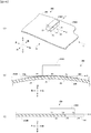
図3等に示すように、演出装置200は、駆動機構210と、可動体250と、を備える。駆動機構210は、可動体250を上下方向に移動させる。可動体250には、パチンコ遊技機1特有の装飾が施されており、このような装飾によって演出効果を高めることができる。可動体250は、駆動機構210により、初期位置(図3(A))から上方へと移動し、進出位置(図3(B))に進出することができる(進出位置から初期位置に戻ることもできる)。可動体250の初期位置では、当該可動体250の大部分が、図示しない透明の樹脂カバー(遊技盤2などに取り付けられている。)の背後に位置し、当該可動体250は、当該樹脂カバーを介して視認される。一方、可動体250は、進出位置に移動することにより画像表示装置5の前方にまで進出し、樹脂カバーを介さずに視認される。なお、遊技盤2を透明とし、可動体250は、少なくとも初期位置において遊技盤2の後方に位置し当該遊技盤2を介して視認させてもよい。
As shown in FIG. 3 and the like, the rendering device 200 includes a drive mechanism 210 and a movable body 250. The drive mechanism 210 moves the movable body 250 in the vertical direction. The movable body 250 is decorated with pachinko gaming machine 1 decoration, and the effect can be enhanced by such decoration. The movable body 250 can move upward from the initial position (FIG. 3A) and advance to the advance position (FIG. 3B) by the drive mechanism 210 (return from the advance position to the initial position). Can also). At the initial position of the movable body 250, most of the movable body 250 is located behind a transparent resin cover (not shown) (attached to the game board 2 or the like). It is visually recognized through. On the other hand, the movable body 250 advances to the front of the image display device 5 by moving to the advance position, and is visually recognized without the resin cover. The game board 2 may be transparent, and the movable body 250 may be positioned behind the game board 2 at least at an initial position and visually recognized via the game board 2.
(駆動機構210の構造等)
まず、図3〜5を参照して駆動機構210を説明する。駆動機構210は、ベース体211、駆動モータ取付部材213、駆動モータ215、第1ギヤ〜第6ギヤ217〜222、検出センサ223、回転アーム225、スライド部材227、弾性体229などを備える(特に、図5を参照)。
(Structure etc. of drive mechanism 210)
First, the drive mechanism 210 will be described with reference to FIGS. The drive mechanism 210 includes a base body 211, a drive motor mounting member 213, a drive motor 215, first to sixth gears 217 to 222, a detection sensor 223, a rotating arm 225, a slide member 227, an elastic body 229, and the like (particularly). , See FIG.
ベース体211は、駆動機構210のベースとなるもので、種々の部品を支持する。ベース体211は、パチンコ遊技機1の遊技盤2等に固定される。なお、ベース体211には、駆動モータ215などを前から覆って遊技者から隠すカバー体CV(図3でのみ図示)が、取り付けられる。ベース体211は、支持体211A〜211F、凹レール211J、ガイド孔211K、引掛部211Lを備える。
The base body 211 is a base of the drive mechanism 210 and supports various components. The base body 211 is fixed to the game board 2 or the like of the pachinko gaming machine 1. A cover body CV (shown only in FIG. 3) that covers the drive motor 215 from the front and hides it from the player is attached to the base body 211. The base body 211 includes supports 211A to 211F, a concave rail 211J, a guide hole 211K, and a hooking portion 211L.
支持体211A〜211Fは、前方に突出した円柱状(円筒状でもよい。以下、円柱状について適宜同じ。)のボスなどからなる。支持体211A〜211Eそれぞれには、第2〜第7ギヤ218〜222それぞれを回転可能に支持する。各ギヤは、その中央に貫通孔を有し、当該貫通孔に支持体が挿入されることで回転可能に支持される。各ギヤは、各支持体の中心軸を回転軸線として回転できる。支持体211Fは、回転アーム225(詳しくは後述する)を回転可能に支持する。
The supports 211A to 211F are made of a boss or the like that protrudes forward (may be a cylindrical shape; hereinafter, the same applies to the columnar shape). The second to seventh gears 218 to 222 are rotatably supported on the supports 211A to 211E, respectively. Each gear has a through hole at the center thereof, and is rotatably supported by inserting a support body into the through hole. Each gear can rotate with the central axis of each support as a rotation axis. The support body 211F rotatably supports a rotating arm 225 (described in detail later).
凹レール211Jは、断面コの字状(縦線が底面)のレールであり、上下方向に延びている。当該凹レール211Jには、可動体250が備えるラック251が、上下にスライド可能に嵌められる。凹レール211Jは、ラック251の移動(つまり、可動体250の移動)の方向を上下方向に案内する。
The concave rail 211J is a rail having a U-shaped cross section (a vertical line is a bottom surface) and extends in the vertical direction. A rack 251 provided in the movable body 250 is fitted to the concave rail 211J so as to be slidable up and down. The concave rail 211J guides the direction of movement of the rack 251 (that is, movement of the movable body 250) in the vertical direction.
ガイド孔211Kは、上下方向に沿って延びる貫通孔であり、スライド部材227が取る付けられる部分に設けられている。スライド部材227には、後方に延びる突起部(図示せず)が設けられており、当該突起部がガイド孔211Kに挿入される。また、突起部の後端には、ガイド孔211Kの幅(左右方向の長さ)よりも大きい抜け留め部材(図示せず)が取り付けられる。これによって、スライド部材227は、前方向に移動しない(ベース体211から抜けない)ように、かつ、上下方向に移動可能(ガイド孔211Kにより案内される)に、ベース体211に取り付けられる。
The guide hole 211K is a through hole extending in the vertical direction, and is provided in a portion to which the slide member 227 is attached. The slide member 227 is provided with a protrusion (not shown) extending rearward, and the protrusion is inserted into the guide hole 211K. A retaining member (not shown) larger than the width (length in the left-right direction) of the guide hole 211K is attached to the rear end of the protrusion. As a result, the slide member 227 is attached to the base body 211 so as not to move in the forward direction (does not come out of the base body 211) and to be movable in the vertical direction (guided by the guide hole 211K).
引掛部211Lは、切り欠きを有する突起部であり、この切り欠きに弾性体229の一端が引っ掛けられる。
The hook portion 211L is a protrusion having a notch, and one end of the elastic body 229 is hooked on the notch.
駆動モータ215は、駆動モータ取付部材213を介してベース体211に取り付けられる。駆動モータ215は、回転軸215Aを有する。駆動モータ215は、ここではステッピングモータであり、演出制御基板12(図2)により動作が制御される。駆動モータ215は、演出制御基板12からの制御信号(ここでは、駆動パルス)に同期して、回転軸215A(図5)を所定の角度だけ回転させる。回転軸215Aには、第1ギヤ217が嵌合されている。従って、第1ギヤ217は、回転軸215Aとともに回転する。第1ギヤ217は、第2ギヤ218と噛み合っている。
The drive motor 215 is attached to the base body 211 via the drive motor attachment member 213. The drive motor 215 has a rotation shaft 215A. Here, the drive motor 215 is a stepping motor, and its operation is controlled by the effect control board 12 (FIG. 2). The drive motor 215 rotates the rotating shaft 215A (FIG. 5) by a predetermined angle in synchronization with a control signal (here, a drive pulse) from the effect control board 12. A first gear 217 is fitted to the rotation shaft 215A. Accordingly, the first gear 217 rotates together with the rotation shaft 215A. The first gear 217 is in mesh with the second gear 218.
第3ギヤ219は、内部の一部がくり抜かれた円柱状の円柱部219Aと、円柱部219Aの後方に配置された外歯車219Bと、を有する。外歯車219Bは、第2ギヤ218と噛み合っている。また、第3ギヤ221は、円柱部219Aの外周面から突出した、円弧状の外縁を有する検出片219Cと、円柱部219Aの外周面から外側に突出し、さらに後方に突出した円柱状の突起体219Dとを有する。
The third gear 219 includes a cylindrical columnar part 219A in which a part of the interior is hollowed out, and an external gear 219B disposed behind the cylindrical part 219A. The external gear 219B meshes with the second gear 218. The third gear 221 includes a detection piece 219C having an arcuate outer edge that protrudes from the outer peripheral surface of the cylindrical portion 219A, and a cylindrical protrusion that protrudes outward from the outer peripheral surface of the cylindrical portion 219A and further protrudes rearward. 219D.
検出片219Cは、第3ギヤ219とともに回転し、ベース体211に取り付けられた検出センサ223により検出される。検出センサ223は、例えば、フォトセンサ(受光部と発光部との間が検出対象により遮蔽されたことを検出するセンサなど)であり、検出片219Cを検出したときに、検出したことを示す検出信号を出力する。後述するように、この実施の形態では、第3ギヤ219の回転に連動して、可動体250が進出位置まで移動する。検出片219Cは、回転ギヤ219Cが、可動体250を進出位置に位置させるまで回転したときに検出センサ223により検出される位置に配置されている。
The detection piece 219 </ b> C rotates with the third gear 219 and is detected by a detection sensor 223 attached to the base body 211. The detection sensor 223 is, for example, a photo sensor (such as a sensor that detects that the space between the light receiving unit and the light emitting unit is shielded by the detection target), and detection that indicates that the detection piece 219C has been detected. Output a signal. As will be described later, in this embodiment, the movable body 250 moves to the advanced position in conjunction with the rotation of the third gear 219. The detection piece 219C is disposed at a position detected by the detection sensor 223 when the rotation gear 219C rotates until the movable body 250 is positioned at the advanced position.
第4ギヤ220は、小径の第1歯車(図示せず)と大径の第2歯車とを回転軸線を共通にして二枚重ねた形状である。第1歯車は、第2歯車よりも後方に位置し、第5ギヤ221と噛み合っている。第2歯車は、可動体250が備えるラック251の歯と噛み合っている。第5ギヤ221及び第6ギヤ222は、スライド部材227が備える直線状の歯227Aと噛み合っている。
The fourth gear 220 has a shape in which a small-diameter first gear (not shown) and a large-diameter second gear are stacked with a common rotation axis. The first gear is located behind the second gear and meshes with the fifth gear 221. The second gear meshes with the teeth of the rack 251 provided in the movable body 250. The fifth gear 221 and the sixth gear 222 are meshed with linear teeth 227A included in the slide member 227.
回転アーム225は、扇形状をなしている。回転アーム225は、可動体250が備える円柱状の突起体252Aが挿入された長孔225Aと、突起体219Dが挿入された長孔225Bと、支持体211Fが挿入された貫通孔225Cと、を備える。貫通孔225Cは、回転アーム225の形状である扇を形成する円の中心に位置している。回転アーム225は、支持体211Cの中心軸を回転軸線として回転可能にベース体211に取り付けられている。長孔225Aは、前記扇の第1の斜辺(前記円の半径により構成される辺)上に配置され、当該第1の斜辺が延びる方向に長尺である。長孔225Bは、前記扇の第2の斜辺上に配置され、当該第2の斜辺が延びる方向に長尺である。長孔225Aの幅(短尺方向の長さ)は、円柱状の突起体252Aの直径と略同じ(当該直径の方が若干短い)である。長孔225Bの幅は、円柱状の突起体219Dの直径と略同じ(当該直径の方が若干短い)である。
The rotating arm 225 has a fan shape. The rotary arm 225 includes a long hole 225A into which the cylindrical protrusion 252A provided in the movable body 250 is inserted, a long hole 225B into which the protrusion 219D is inserted, and a through hole 225C into which the support body 211F is inserted. Prepare. The through hole 225 </ b> C is located at the center of a circle that forms a fan having the shape of the rotary arm 225. The rotation arm 225 is attached to the base body 211 so as to be rotatable about the central axis of the support body 211C as a rotation axis. The long hole 225A is disposed on the first hypotenuse (the side constituted by the radius of the circle) of the fan, and is long in the direction in which the first hypotenuse extends. The long hole 225 </ b> B is disposed on the second hypotenuse of the fan and is long in the direction in which the second hypotenuse extends. The width (length in the short direction) of the long hole 225A is substantially the same as the diameter of the cylindrical protrusion 252A (the diameter is slightly shorter). The width of the long hole 225B is substantially the same as the diameter of the cylindrical protrusion 219D (the diameter is slightly shorter).
スライド部材227は、第5ギヤ221及び第6ギヤ222と噛み合う直線状の歯227A(上下方向に延びている)を備え、第5ギヤ221及び第6ギヤ222をピニオンとするラックとして機能する。また、スライド部材227は、下部(スライド部材227の引掛部227Bの下方)に、切り欠きを有する引掛部227Bを備え、弾性体229の他端が引っ掛けられる。上述のように、スライド部材227は、ベース体211に対して上下方向に移動(スライド)可能である。上記のように、第5ギヤ221は、第4ギヤ220とスライド部材227の歯227Aとに噛み合っており、さらに、第4ギヤ220(ピニオン)は、可動体250が備えるラック251の歯に噛み合っている。従って、スライド部材227は、可動体250と連動している。具体的には、スライド部材227が上方に移動すると、可動体250も上方に移動する(図3などを参照)。なお、第6ギヤ222は、スライド部材227が傾かないように当該スライド部材227をガイドしている。
The slide member 227 includes linear teeth 227A (extending in the vertical direction) that mesh with the fifth gear 221 and the sixth gear 222, and functions as a rack having the fifth gear 221 and the sixth gear 222 as pinions. In addition, the slide member 227 includes a hook portion 227B having a notch at a lower portion (below the hook portion 227B of the slide member 227), and the other end of the elastic body 229 is hooked. As described above, the slide member 227 can move (slide) in the vertical direction with respect to the base body 211. As described above, the fifth gear 221 meshes with the fourth gear 220 and the teeth 227A of the slide member 227, and the fourth gear 220 (pinion) meshes with the teeth of the rack 251 included in the movable body 250. ing. Therefore, the slide member 227 is interlocked with the movable body 250. Specifically, when the slide member 227 moves upward, the movable body 250 also moves upward (see FIG. 3 and the like). The sixth gear 222 guides the slide member 227 so that the slide member 227 does not tilt.
弾性体229は、コイルバネ、ゴムなどを含んで構成される。弾性体229の一端は、ベース体211の引掛部211Lに引っ掛けられており、弾性体229の他端は、スライド部材227の引掛部227Bに引っ掛けられている。そして、弾性体229は、スライド部材227が最下位置に位置するとき(図3(A)や図5〜図4の状態のとき)に、延びた状態になる。つまり、スライド部材227は、弾性体229の弾性力により上方に付勢されている(上方への力を受けている)。上記のようにスライド部材227と可動体250とは連動しているので、可動体250も弾性体229の弾性力により上方に付勢されている。つまり、弾性体229は、可動体250の上方への移動を補助している。
The elastic body 229 includes a coil spring, rubber, and the like. One end of the elastic body 229 is hooked on the hook portion 211L of the base body 211, and the other end of the elastic body 229 is hooked on the hook portion 227B of the slide member 227. And the elastic body 229 will be in the extended state, when the slide member 227 is located in the lowest position (at the time of FIG. 3 (A) or the state of FIGS. 5-4). That is, the slide member 227 is biased upward by the elastic force of the elastic body 229 (receives an upward force). Since the slide member 227 and the movable body 250 are interlocked as described above, the movable body 250 is also biased upward by the elastic force of the elastic body 229. That is, the elastic body 229 assists the upward movement of the movable body 250.
(駆動機構210の作用等)
駆動モータ215が回転軸215Aを正回転(左回転)させると、第1ギヤ217も正回転する。第1ギヤ217には第2ギヤ218が噛み合っており、第2ギヤ218は第3ギヤ219に噛み合っているので、回転軸215Aが正回転することにより、第2ギヤ218が逆回転(右回転)し、第3ギヤ219が正回転する。第3ギヤ219の正回転により、突起体219Dも円弧を描きながら移動する。突起体219Dは、移動に伴って長孔225Bの内壁を押す。これにより、回転アーム225は、支持体211Fを中心に上方向(左回り)に回転する。回転アーム225の回転により、長孔225Aに挿入されている可動体250が備える突起体252Aを上方に移動させる。これにより、可動体250が上方(進出位置)に移動する。駆動モータ215が回転軸215Aを逆回転させたときには、可動体250は下方(初期位置)に移動する(各ギヤの回転方向を逆方向にして考えればよい)。このように、駆動機構210は、駆動モータ215の回転力を、可動体250を上下方向に移動させる駆動力に変換する。なお、上記のように、可動体250の上方への移動は、弾性体229により補助される。また、弾性体229は、可動体250が下方に移動することに対して抵抗となる。これにより、可動体250の重量による駆動モータ215への負荷を低減でき、可動体250の上下方向の移動をスムーズにできる。
(Operation of the drive mechanism 210, etc.)
When the drive motor 215 rotates the rotation shaft 215A in the normal direction (left rotation), the first gear 217 also rotates in the normal direction. Since the second gear 218 is engaged with the first gear 217 and the second gear 218 is engaged with the third gear 219, the rotation of the rotation shaft 215A causes the second gear 218 to rotate in the reverse direction (right rotation). ) And the third gear 219 rotates forward. Due to the forward rotation of the third gear 219, the protrusion 219D also moves while drawing an arc. The protrusion 219D pushes the inner wall of the long hole 225B as it moves. Thereby, the rotating arm 225 rotates upward (counterclockwise) around the support body 211F. By the rotation of the rotary arm 225, the protrusion 252A included in the movable body 250 inserted in the long hole 225A is moved upward. Thereby, the movable body 250 moves upward (advance position). When the drive motor 215 rotates the rotating shaft 215A in the reverse direction, the movable body 250 moves downward (initial position) (the rotation direction of each gear may be considered as the reverse direction). Thus, the drive mechanism 210 converts the rotational force of the drive motor 215 into a drive force that moves the movable body 250 in the vertical direction. As described above, the upward movement of the movable body 250 is assisted by the elastic body 229. Further, the elastic body 229 becomes a resistance against the movable body 250 moving downward. Thereby, the load on the drive motor 215 due to the weight of the movable body 250 can be reduced, and the movable body 250 can move smoothly in the vertical direction.
なお、パチンコ遊技機1の電源がオフされるときには、可動体250を進出位置で停止させるようにしてもよい。これにより、弾性体229が伸びた状態の期間を短くでき、当該弾性体の弾性力が時間が経過するにつれて弱くなってしまうことを軽減できる。
When the power of the pachinko gaming machine 1 is turned off, the movable body 250 may be stopped at the advanced position. Thereby, the period in which the elastic body 229 is extended can be shortened, and the elastic force of the elastic body can be reduced from becoming weaker as time elapses.
なお、可動体250を上下方向に移動させるのは、演出制御基板12(演出制御用CPU120)の制御のもとで行われる。具体的には、演出制御基板12は、可動体250を初期位置から進出位置に移動させるときは、駆動モータ215を制御して回転軸215Aを回転させ、検出センサ223により検出片219Cを検出したとき(検出センサ223から検出信号を受信したとき又は検出信号を一定期間受信したとき)、つまり、可動体250が進出位置まで移動したときに、回転軸215Aの回転を停止させる。これにより、可動体250を進出位置で停止させることができる。可動体250を進出位置から初期位置に戻すときには、前記初期位置から進出位置に移動させたときの回転角と同じ分だけ(例えば、その情報をRAM122に保持しておく。)、駆動モータ215の回転軸215Aを逆回転させる。例えば、供給した駆動パルスの数をカウントしておき、逆回転時に同じ数の駆動パルスを供給することで回転軸215Aを逆回転させる。なお、可動体250が初期位置にあるときの検出片219Cの位置に対応して検出センサ(検出センサ223と同じセンサなど。例えば、フォトセンサ)を設けておき、当該検出センサにより検出片219Cを検出したときに、回転軸215Aの逆回転を停止してもよい。
The movable body 250 is moved in the vertical direction under the control of the effect control board 12 (effect control CPU 120). Specifically, when moving the movable body 250 from the initial position to the advanced position, the effect control board 12 controls the drive motor 215 to rotate the rotating shaft 215A and detects the detection piece 219C by the detection sensor 223. When the detection signal is received from the detection sensor 223 or when the detection signal is received for a certain period, that is, when the movable body 250 moves to the advanced position, the rotation of the rotating shaft 215A is stopped. Thereby, the movable body 250 can be stopped at the advance position. When the movable body 250 is returned from the advanced position to the initial position, the drive motor 215 has the same rotation angle as that when the movable body 250 is moved from the initial position to the advanced position (for example, the information is held in the RAM 122). The rotating shaft 215A is reversely rotated. For example, the number of supplied drive pulses is counted, and the same number of drive pulses is supplied during reverse rotation, whereby the rotary shaft 215A is reversely rotated. A detection sensor (the same sensor as the detection sensor 223, for example, a photo sensor) is provided corresponding to the position of the detection piece 219C when the movable body 250 is in the initial position, and the detection piece 219C is attached by the detection sensor. When detected, the reverse rotation of the rotating shaft 215A may be stopped.
(可動体250の構造等)
次に可動体250の構造詳細を、図6〜図15を用いて説明する。可動体250は、ハート形の装飾体269と、その前方に設けたLOVEの文字を表す部材と、を有し、装飾体269が変形したり、LOVEの各文字が動いたりすることで、演出効果の高い演出を実行する。
(Structure of movable body 250, etc.)
Next, the detailed structure of the movable body 250 will be described with reference to FIGS. The movable body 250 includes a heart-shaped decorative body 269 and a member representing a LOVE character provided in front of the movable body 250, and the decorative body 269 is deformed or each LOVE character moves, Perform a highly effective performance.
可動体250は、ラック251と、板状部材252と、基板253と、ベース体255と、LED基板256と、駆動モータ257と、検出センサ259と、第1〜第3ギヤ261〜263と、第1〜第2スライド部材265〜266と、第1〜第2取付部材267〜268と、装飾体269と、所定機構X(「LOVE」を形成する部材及び「LOVE」の各文字を動かす機構)と、を備える。
The movable body 250 includes a rack 251, a plate-like member 252, a substrate 253, a base body 255, an LED substrate 256, a drive motor 257, a detection sensor 259, first to third gears 261 to 263, First to second slide members 265 to 266, first to second mounting members 267 to 268, a decorative body 269, a predetermined mechanism X (a member that forms “LOVE” and a mechanism that moves each character of “LOVE”) And).
(可動体250における所定機構X以外の構成)
まず、図6〜図7などを参照して、所定機構X以外の構成について説明する。
(Configuration other than the predetermined mechanism X in the movable body 250)
First, a configuration other than the predetermined mechanism X will be described with reference to FIGS.
ラック251は、第4ギヤ220(図5など)と噛み合う、上下方向に延びた歯を有する。ラック251は、上記から分かるように、弾性体229(図5など)により、第4ギヤ220などを介して上方向に付勢されている。
The rack 251 has teeth extending in the vertical direction that mesh with the fourth gear 220 (FIG. 5 and the like). As can be seen from the above, the rack 251 is urged upward by the elastic body 229 (FIG. 5 and the like) via the fourth gear 220 and the like.
板状部材252は、ラック251と一体的に形成されている。板状部材252は、板状の本体から後方に突出した円柱状の突起体252Aを有する。
The plate member 252 is formed integrally with the rack 251. The plate-like member 252 has a columnar protrusion 252A that protrudes rearward from the plate-like main body.
基板253は、所定の回路を有し、演出制御基板12と電気的に接続された回路基板である。基板253は、演出制御基板12から駆動モータ257、後述の駆動モータ273、後述のLED基板275等に供給される制御信号を中継するとともに、後述の検出センサ259、後述の検出センサSから演出制御基板12に供給される検出信号を中継する。基板253は、ベース体255の後面に取り付けられている。基板253は貫通孔や切り欠きを有し、板状部材252が当該貫通孔や切り欠きを介してネジ、ビス等によりベース体255の後面に取り付けられる。これにより、ラック251もベース体255に取り付けられたことになる。
The board 253 is a circuit board that has a predetermined circuit and is electrically connected to the effect control board 12. The board 253 relays control signals supplied from the effect control board 12 to the drive motor 257, the drive motor 273 described later, the LED board 275 described later, and the like, and the effect control is performed from the detection sensor 259 described later and the detection sensor S described later. The detection signal supplied to the substrate 12 is relayed. The substrate 253 is attached to the rear surface of the base body 255. The substrate 253 has a through hole and a notch, and the plate-like member 252 is attached to the rear surface of the base body 255 with a screw, a screw or the like through the through hole or the notch. As a result, the rack 251 is also attached to the base body 255.
ベース体255は、可動体250のベースとなり、前面及び後面に種々の部品を支持する。ベース体255は、前面に左右方向に延びるラック部255A、255Bを備える(これらは、所定機構Xで使用される)。また、ベース体255は、周囲(後面等)よりも後方に突出した円柱状のボスなどからなる突起体255C〜255Hを備える。ベース体255は、周囲(前面等)よりも前方に突出した円柱状のボスなどからなる突起体255I〜255Lを備える(これらは、所定機構Xで使用される)。ベース体255は、図示しない検出センサ(説明のため検出センサSとする。)が固定される固定部255Jも備える。当該検出センサSは、後述の第2スライド部材266の検出片266Dを検出するものであり、検出センサ223と同様にフォトセンサ等であればよい。また、ベース体255の上部には、LED基板256が差し込まれ、該LED基板256を固定するための複数の差込部255Mが形成されている。
The base body 255 serves as a base for the movable body 250 and supports various components on the front surface and the rear surface. The base body 255 includes rack portions 255A and 255B extending in the left-right direction on the front surface (these are used in the predetermined mechanism X). In addition, the base body 255 includes protrusions 255C to 255H made of a columnar boss or the like that protrudes rearward from the periphery (rear surface or the like). The base body 255 includes protrusions 255I to 255L made of a cylindrical boss or the like that protrudes forward from the periphery (front surface or the like) (these are used in the predetermined mechanism X). The base body 255 also includes a fixing portion 255J to which a detection sensor (not shown) (referred to as a detection sensor S for explanation) is fixed. The detection sensor S detects a detection piece 266D of a second slide member 266, which will be described later, and may be a photo sensor or the like, similar to the detection sensor 223. In addition, an LED substrate 256 is inserted into the upper portion of the base body 255, and a plurality of insertion portions 255M for fixing the LED substrate 256 are formed.
LED基板256は、差込部255M及び差込部271C(図8参照)により、ベース体255の湾曲した上面に保持されている。LED基板256の基板本体256Bは、ベース体255の形状に合わせて湾曲した形状を有している。LED基板256は、基板253と電気的に接続されており、各種の回路や、光を出射するLED256A及びコネクタ256Cを、基板本体256Bに実装している。なお、光源としてLED256A以外の他の光源を採用してもよい。LED基板256は、基板253が中継した演出制御基板12からの制御信号に基づき、LED256Aを発光させる。LED256Aの発光により、装飾体269の上部が照明される。装飾体269は、光を透過可能なので、LED256Aからの光によって上部が発光して見える。なお、LED基板256の詳細については後述する。
The LED substrate 256 is held on the curved upper surface of the base body 255 by the insertion portion 255M and the insertion portion 271C (see FIG. 8). The substrate body 256B of the LED substrate 256 has a curved shape in accordance with the shape of the base body 255. The LED board 256 is electrically connected to the board 253, and various circuits, LEDs 256A for emitting light, and connectors 256C are mounted on the board body 256B. A light source other than the LED 256A may be employed as the light source. The LED board 256 causes the LED 256 </ b> A to emit light based on a control signal from the effect control board 12 relayed by the board 253. The upper part of the decorative body 269 is illuminated by the light emission of the LED 256A. Since the decorative body 269 can transmit light, the upper part appears to emit light by the light from the LED 256A. Details of the LED substrate 256 will be described later.
駆動モータ257は、ベース体255の前面に取り付けられる。駆動モータ257の回転軸257Aは、ベース体255に設けられた貫通孔を通り、ベース体255の後方に延びている。駆動モータ257は、演出制御基板12からの制御信号(駆動パルスなど)により動作する。
The drive motor 257 is attached to the front surface of the base body 255. The rotation shaft 257A of the drive motor 257 passes through a through hole provided in the base body 255 and extends to the rear of the base body 255. The drive motor 257 is operated by a control signal (such as a drive pulse) from the effect control board 12.
検出センサ259は、ベース体255の前面に取り付けられている。検出センサ259の検出対象等については後述する(所定機構Xで使用される)。検出センサ259は、検出センサ223と同様にフォトセンサ等であればよい。
The detection sensor 259 is attached to the front surface of the base body 255. The detection target of the detection sensor 259 will be described later (used in the predetermined mechanism X). The detection sensor 259 may be a photo sensor or the like, similar to the detection sensor 223.
第1ギヤ261は、駆動モータ257の回転軸257Aに嵌合されており、回転軸257Aとともに回転する。第1ギヤ261には、当該第1ギヤ261の左右に配置された第2ギヤ262及び第3ギヤ263が噛み合っている。第2ギヤ262は、その中央に形成された貫通孔に突起体255Cが挿入されることで、ベース体255に回転可能に支持されている。第3ギヤ263は、その中央に形成された貫通孔に突起体255Dが挿入されることで、ベース体255に回転可能に支持されている。各ギヤは、各突起体の中心軸を回転軸線として回転できる。第2ギヤ262は、後方に突出した円柱状の突起体262Aを備える。第3ギヤ263は、後方に突出した円柱状の突起体263Aを備える。
The first gear 261 is fitted to the rotation shaft 257A of the drive motor 257 and rotates together with the rotation shaft 257A. The first gear 261 meshes with the second gear 262 and the third gear 263 arranged on the left and right sides of the first gear 261. The second gear 262 is rotatably supported by the base body 255 by inserting a protrusion 255C into a through hole formed at the center thereof. The third gear 263 is rotatably supported by the base body 255 by inserting a protrusion 255D into a through hole formed at the center thereof. Each gear can rotate with the central axis of each protrusion as a rotation axis. The second gear 262 includes a columnar protrusion 262A that protrudes rearward. The third gear 263 includes a columnar protrusion 263A protruding rearward.
第1スライド部材265は、右側端部に上下方向に長尺な長孔265Aと、中央に左右方向に長尺な長孔265Bとを備える。長孔265Aには、突起体262Aが挿入されている。長孔265Aの幅(左右方向の長さ)は、突起体262Aの直径と略同じ(当該直径の方が若干短い)である。突起体262Aは、長孔265A内を移動できる。長孔265Bには、左右方向に一例に並んだ突起体255E、255Fが挿入されている。長孔265Bの幅(上下方向の長さ)は、突起体255E、255Fの直径と略同じ(当該直径の方が若干短い)である。突起体255E、255Fは、長孔265B内を移動できる。突起体255E、255Fは、第1スライド部材265が左右方向以外に動いてしまうのを規制している。第1スライド部材265は、左側端部に2つの小孔265Cを有する。
The first slide member 265 includes a long hole 265A elongated in the vertical direction at the right end and a long hole 265B elongated in the horizontal direction at the center. A protrusion 262A is inserted into the long hole 265A. The width (length in the left-right direction) of the long hole 265A is substantially the same as the diameter of the protrusion 262A (the diameter is slightly shorter). The protrusion 262A can move in the long hole 265A. Projections 255E and 255F arranged in the left-right direction as an example are inserted into the long holes 265B. The width (length in the vertical direction) of the long hole 265B is substantially the same as the diameter of the protrusions 255E and 255F (the diameter is slightly shorter). The protrusions 255E and 255F can move in the long hole 265B. The protrusions 255E and 255F restrict the first slide member 265 from moving in directions other than the left-right direction. The first slide member 265 has two small holes 265C at the left end.
第2スライド部材266は、左側端部に上下方向に長尺な長孔266Aと、中央に左右方向に長尺な長孔266Bとを備える。長孔266Aには、突起体263Aが挿入されている。長孔266Aの幅(左右方向の長さ)は、突起体263Aの直径と略同じ(当該直径の方が若干短い)である。突起体263Aは、長孔266A内を移動できる。長孔266Bには、左右方向に一例に並んだ突起体255G、255Hが挿入されている。長孔266Bの幅(上下方向の長さ)は、突起体255G、255Hの直径と略同じ(当該直径の方が若干短い)である。突起体255G、255Hは、長孔266B内を移動できる。突起体255G、255Hは、第2スライド部材266が左右方向以外に動いてしまうのを規制している。第2スライド部材266は、右側端部に2つの小孔266Cを有する。
The second slide member 266 includes a long hole 266A elongated in the vertical direction at the left end portion and a long hole 266B elongated in the horizontal direction at the center. A protrusion 263A is inserted into the long hole 266A. The width (length in the left-right direction) of the long hole 266A is substantially the same as the diameter of the protrusion 263A (the diameter is slightly shorter). The protrusion 263A can move in the long hole 266A. In the long hole 266B, protrusions 255G and 255H arranged in one example in the left-right direction are inserted. The width (length in the vertical direction) of the long hole 266B is substantially the same as the diameter of the protrusions 255G and 255H (the diameter is slightly shorter). The protrusions 255G and 255H can move in the long hole 266B. The protrusions 255G and 255H restrict the second slide member 266 from moving in directions other than the left-right direction. The second slide member 266 has two small holes 266C at the right end.
また、第2スライド部材266は、検出センサSにより検出される検出片266Dを備える。検出片266Dは、第2スライド部材266が初期位置にあるとき(後述の装飾体が変形していないとき。図12(A)の状態)に検出センサSにより検出される位置に配置されている。検出センサSは、検出片266Dを検出すると、その旨を示す検出信号を演出制御基板12に供給する。
The second slide member 266 includes a detection piece 266D detected by the detection sensor S. The detection piece 266D is disposed at a position that is detected by the detection sensor S when the second slide member 266 is in the initial position (when a decorative body that will be described later is not deformed, as shown in FIG. 12A). . When detecting the detection piece 266D, the detection sensor S supplies a detection signal indicating that to the effect control board 12.
第1取付部材267は、装飾体269(詳細は後述する)の内側に配置される。第1取付部材267は、後方に突出した2つの小径棒267Aを有する。2つの小径棒267Aは、それぞれ、装飾体269の張り出し部269Eに設けられた2つの小孔269Fそれぞれを通り、第1スライド部材265の2つの小孔265Cそれぞれに嵌合される。従って、第1取付部材267は、装飾体269の張り出し部269Eを挟み込んで、第1スライド部材265の左側端部に取り付けられる。第1取付部材267は、左右方向に延びる貫通孔267Bを有する。第1取付部材267のうち、貫通孔267Bを形成する部分は、装飾体269の貫通孔269Aに入り込む形状である(図8等も参照。第1取付部材267は、一部、装飾体269の外側から視認できる)。従って、貫通孔269Aの内側に貫通孔267Bが配置される。
The first attachment member 267 is disposed inside the decorative body 269 (details will be described later). The first mounting member 267 has two small-diameter bars 267A that protrude rearward. The two small-diameter bars 267A are respectively fitted into the two small holes 265C of the first slide member 265 through the two small holes 269F provided in the projecting portion 269E of the decorative body 269. Accordingly, the first attachment member 267 is attached to the left end portion of the first slide member 265 with the projecting portion 269E of the decorative body 269 interposed therebetween. The first attachment member 267 has a through hole 267B extending in the left-right direction. Of the first mounting member 267, a portion where the through hole 267B is formed has a shape that enters the through hole 269A of the decorative body 269 (see also FIG. 8 and the like. The first mounting member 267 is a part of the decorative body 269). Visible from outside). Accordingly, the through hole 267B is disposed inside the through hole 269A.
第2取付部材268は、装飾体269(詳細は後述する)の内側に配置される。第2取付部材268は、後方に突出した2つの小径棒268Aを有する。2つの小径棒268Aは、それぞれ、装飾体269の張り出し部269Eに設けられた2つの小孔269Gそれぞれを通り、第2スライド部材266の2つの小孔266Cそれぞれに嵌合される。従って、第2取付部材268は、装飾体269の張り出し部269Eを挟み込んで、第2スライド部材266の右側端部に取り付けられる。第2取付部材268は、左右方向に延びる貫通孔268Bを有する。第2取付部材268のうち、貫通孔268Bを形成する部分は、装飾体269の貫通孔269Dに入り込む形状である(図8等も参照。第2取付部材268は、一部、装飾体269の外側から視認できる)。従って、貫通孔269Dの内側に貫通孔268Bが配置される。
The second attachment member 268 is disposed inside the decorative body 269 (details will be described later). The second mounting member 268 has two small-diameter bars 268A protruding rearward. The two small diameter bars 268A pass through the two small holes 269G provided in the projecting portion 269E of the decorative body 269, respectively, and are fitted into the two small holes 266C of the second slide member 266, respectively. Therefore, the second attachment member 268 is attached to the right end portion of the second slide member 266 with the projecting portion 269E of the decorative body 269 interposed therebetween. The second mounting member 268 has a through hole 268B extending in the left-right direction. Of the second mounting member 268, the portion where the through hole 268 </ b> B is formed has a shape that enters the through hole 269 </ b> D of the decorative body 269 (see also FIG. 8 and the like. The second mounting member 268 is a part of the decorative body 269. Visible from outside). Accordingly, the through hole 268B is disposed inside the through hole 269D.
装飾体269は、前方向に膨らんだハート形状であり、光を透過可能な部材である。装飾体269は、所定の装飾が施されている。装飾体269は、例えば、天然ゴム製、又は、シリコーンゴムを含む各種の合成ゴム製であり、弾性変形可能となっている。装飾体269は、その側部に貫通孔269A、269Dが、前部に貫通孔269B、269Cが設けられている。貫通孔269A、269Dそれぞれには、第1取付部材267、第2取付部材268それぞれの端部が入り込む。装飾体269は、その側部の後端から内側に張り出した張り出し部269Eを有する。装飾体269の張り出し部269Eには、2つの小孔269Fと2つの小孔269Gとが設けられ、これらに、第1取付部材267の小径棒267A(第1スライド部材265の2つの小孔265Cに嵌合される。)及び第2取付部材268の小径棒268A(第2スライド部材266の2つの小孔266Cに嵌合される。)が通っている。このため、装飾体269は、小孔269Fが設けられた左側端部で第1取付部材267及び第1スライド部材265と連結し、小孔269Gが設けられた右側端部で第2取付部材268及び第2スライド部材266と連結している。また、装飾体269の貼り出し部269Eの上部には、略三角形状の切欠き269H及び切欠き269Iが形成されている。装飾体269に左右方向から圧縮するような力が作用すると、切欠き269H及び切欠き269Iは切り欠かれた部分を閉じる。これにより、装飾体269は左右方向からの圧縮力により容易に変形する。なお、装飾体269は、ベース体255等をその内部に収容している。従って、可動体250を動作させる構成のサイズをコンパクトにしている。
The decorative body 269 has a heart shape that swells in the forward direction, and is a member that can transmit light. The decorative body 269 is given a predetermined decoration. The decorative body 269 is made of, for example, natural rubber or various synthetic rubbers including silicone rubber, and can be elastically deformed. The decorative body 269 is provided with through-holes 269A and 269D on its side and through-holes 269B and 269C on the front. The end portions of the first mounting member 267 and the second mounting member 268 enter the through holes 269A and 269D, respectively. The decorative body 269 has a protruding portion 269E that protrudes inward from the rear end of the side portion. The protruding portion 269E of the decorative body 269 is provided with two small holes 269F and two small holes 269G, which are provided with a small-diameter bar 267A of the first mounting member 267 (two small holes 265C of the first slide member 265). And a small-diameter bar 268A of the second mounting member 268 (which is fitted into the two small holes 266C of the second slide member 266). Therefore, the decorative body 269 is connected to the first attachment member 267 and the first slide member 265 at the left end portion provided with the small hole 269F, and the second attachment member 268 at the right end portion provided with the small hole 269G. And the second slide member 266. Further, a substantially triangular cutout 269H and a cutout 269I are formed on the upper portion of the sticking portion 269E of the decorative body 269. When a force that compresses the decorative body 269 from the left-right direction is applied, the notch 269H and the notch 269I close the notched portion. Thereby, the decorative body 269 is easily deformed by the compressive force from the left-right direction. The decorative body 269 houses the base body 255 and the like therein. Therefore, the size of the configuration for operating the movable body 250 is made compact.
(装飾体269の変形のための動作)
駆動モータ257が回転軸257Aを正回転(右回転)させると、第1ギヤ261も正回転する。第1ギヤ261には第2ギヤ262及び第3ギヤ263が噛み合っており、回転軸257Aが正回転することにより、第2ギヤ262及び第3ギヤ263は逆回転(左回転)する。ここで、第2ギヤ262の突起体262Aは、第2ギヤ262の上側部分に設けられており、一方で、第2ギヤ263の突起体263Aは、第2ギヤ263の下側部分に設けられている。従って、第2ギヤ262及び第3ギヤ263が逆回転すると、突起体262Aが左側に移動し、突起体263Aが右側に移動する。つまり、突起体262A及び突起体263Aは、各ギヤの回転軸線を基準に対象の位置にあることで、互いに離れる方向に移動する。左方向に移動する突起体262Aは、第1スライド部材265の長孔265Aの内壁を押し、当該第1スライド部材265を左にスライドさせる(第1取付部材267も一緒に移動する)。右方向に移動する突起体263Aは、第2スライド部材266の長孔266Aの内壁を押し、当該第2スライド部材266を右にスライドさせる(第2取付部材268も一緒に移動する)。このように、第1スライド部材265(及び第1取付部材267)と、第2スライド部材266(及び第2取付部材268)とは左右方向に沿って互いに離れる方向に移動する。
(Operation for deforming the decorative body 269)
When the drive motor 257 rotates the rotation shaft 257A in the normal direction (right rotation), the first gear 261 also rotates in the normal direction. The first gear 261 is engaged with the second gear 262 and the third gear 263, and the second gear 262 and the third gear 263 are rotated in the reverse direction (left rotation) when the rotation shaft 257A is rotated forward. Here, the protrusion 262A of the second gear 262 is provided on the upper part of the second gear 262, while the protrusion 263A of the second gear 263 is provided on the lower part of the second gear 263. ing. Therefore, when the second gear 262 and the third gear 263 rotate in the reverse direction, the protrusion 262A moves to the left and the protrusion 263A moves to the right. In other words, the protrusions 262A and the protrusions 263A move in directions away from each other because the protrusions 262A and the protrusions 263A are at target positions with respect to the rotation axis of each gear. The protrusion 262A that moves to the left pushes the inner wall of the elongated hole 265A of the first slide member 265, and slides the first slide member 265 to the left (the first attachment member 267 also moves together). The protrusion 263A that moves to the right pushes the inner wall of the long hole 266A of the second slide member 266, and slides the second slide member 266 to the right (the second attachment member 268 also moves together). As described above, the first slide member 265 (and the first attachment member 267) and the second slide member 266 (and the second attachment member 268) move in the direction away from each other along the left-right direction.
駆動モータ257が回転軸257Aを逆回転させると、上記とは逆方向の動作が行われ、第1スライド部材265及び第1取付部材267と、第2スライド部材266及び第2取付部材268とは左右方向に沿って互いに近づく方向に移動する。
When the drive motor 257 rotates the rotating shaft 257A in the reverse direction, the operation in the reverse direction is performed, and the first slide member 265 and the first attachment member 267, and the second slide member 266 and the second attachment member 268 are the same. Move in a direction approaching each other along the left-right direction.
第1スライド部材265及び第1取付部材267は装飾体269の左側端部を挟み込んだ状態で連結されているので、これらの左右の移動に伴って当該左側端部も左右に移動する。第2スライド部材266及び第2取付部材268は装飾体269の右側端部を挟み込んだ状態で連結されているので、これらの左右の移動に伴って当該右側端部も左右に移動する。従って、駆動モータ257が回転軸257Aを正回転させると、装飾体269は、左右両方から引っ張られるように弾性変形し(図12(B)の特に左側の図参照)、回転軸257Aを逆回転させると、装飾体269は、左右両方から押されたように弾性変形する(図12(C)の特に左側の図参照)。なお、上述したように、装飾体269の貼り出し部269Eの上部には、略三角形状の切欠き269H及び切欠き269Iが形成されている。これにより、装飾体269が左右両方から押され圧縮されると、略三角形状に形成された切欠きが閉じ、装飾体269は容易に変形する。
Since the first slide member 265 and the first attachment member 267 are connected in a state where the left end portion of the decorative body 269 is sandwiched, the left end portion also moves left and right along with the left and right movements. Since the second slide member 266 and the second attachment member 268 are connected in a state where the right end portion of the decorative body 269 is sandwiched, the right end portion also moves left and right along with the left and right movement thereof. Therefore, when the drive motor 257 rotates the rotating shaft 257A in the normal direction, the decorative body 269 is elastically deformed so as to be pulled from both the left and right sides (see the left side in FIG. 12B), and the rotating shaft 257A rotates in the reverse direction. Then, the decorative body 269 is elastically deformed as if pressed from both the left and right sides (see the left side of FIG. 12C in particular). As described above, a substantially triangular cutout 269H and a cutout 269I are formed in the upper portion of the sticking portion 269E of the decorative body 269. Accordingly, when the decorative body 269 is pressed from both the left and right sides and is compressed, the notch formed in a substantially triangular shape is closed, and the decorative body 269 is easily deformed.
上記のように、駆動モータ257は、演出制御基板12により制御される。演出制御基板12は、制御信号を駆動モータ257に供給することで、回転軸257Aを正回転させることと、逆回転させることとを繰り返す。そうすると、装飾体269は、左右に引っ張られるように弾性変形することと、左右から押されるように弾性変形することとを繰り返す。これにより、ハート形の装飾体269は、心臓のように鼓動して見える(図12、図16参照)。なお、演出制御基板12は、検出センサSにより、第2スライド部材266が初期位置にあること(つまり、装飾体269が初期状態にあること(図12(A)の状態))を検出する。演出制御基板12は、検出センサSからの検出信号を受信したとき(又は所定期間にわたって受信したとき)に、第2スライド部材266が初期位置にあることを検出する。なお、第2スライド部材266が図12(B)や(C)の位置にあるときの検出片266Dの位置に検出センサを設け、可動体250が図12(B)や(C)の状態にあることを検出し、この検出に基づいて駆動モータ257の回転軸257Aの回転方向を制御してもよい。
As described above, the drive motor 257 is controlled by the effect control board 12. The effect control board 12 repeats rotating the rotating shaft 257A forward and rotating backward by supplying a control signal to the drive motor 257. Then, the decorative body 269 repeats elastic deformation so as to be pulled left and right and elastic deformation so as to be pushed from the left and right. Thereby, the heart-shaped decorative body 269 looks like a heart (see FIGS. 12 and 16). Note that the effect control board 12 detects that the second slide member 266 is in the initial position (that is, the decorative body 269 is in the initial state (the state shown in FIG. 12A)) by the detection sensor S. The effect control board 12 detects that the second slide member 266 is in the initial position when the detection signal from the detection sensor S is received (or when it is received over a predetermined period). A detection sensor is provided at the position of the detection piece 266D when the second slide member 266 is at the position shown in FIGS. 12B and 12C, and the movable body 250 is brought into the state shown in FIGS. It may be detected that the rotation direction of the rotation shaft 257A of the drive motor 257 is controlled based on this detection.
(所定機構Xの構造等)
次に、所定機構Xの詳細構造を、図8〜図11などを参照して説明する。所定機構Xは、カバー体271と、駆動モータ273と、LED基板275と、カバー体277と、第1〜第4文字部材281〜284と、駆動力伝達機構X1と、を有する(図8参照)。
(Structure of the predetermined mechanism X)
Next, the detailed structure of the predetermined mechanism X will be described with reference to FIGS. The predetermined mechanism X includes a cover body 271, a drive motor 273, an LED board 275, a cover body 277, first to fourth character members 281 to 284, and a driving force transmission mechanism X1 (see FIG. 8). ).
カバー体271は、駆動力伝達機構X1などが取り付けられたベース体255に前方から取り付けられることで、ベース体255を前方からカバーする。カバー体271は、貫通孔271A〜271B(これらの用途等については後述する)を有する。また、カバー体271の上部には、LED基板256が差し込まれ、該LED基板256を固定するための複数の差込部271Cが形成されている。
The cover body 271 covers the base body 255 from the front by being attached to the base body 255 to which the driving force transmission mechanism X1 and the like are attached. The cover body 271 has through holes 271A to 271B (these applications will be described later). Further, the LED board 256 is inserted into the upper portion of the cover body 271, and a plurality of insertion portions 271 </ b> C for fixing the LED board 256 are formed.
駆動モータ273は、カバー体271の前面に取り付けられる。駆動モータ273の回転軸は、カバー体271に設けられた貫通孔を通り、カバー体271の後方に延びている。駆動モータ273は、演出制御基板12からの制御信号(駆動パルスなど)により動作する。
The drive motor 273 is attached to the front surface of the cover body 271. The rotation shaft of the drive motor 273 passes through a through hole provided in the cover body 271 and extends behind the cover body 271. The drive motor 273 is operated by a control signal (such as a drive pulse) from the effect control board 12.
LED基板275は、基板253と電気的に接続される。LED基板275は、各種の回路や、前方(装飾体269)に光を出射するLED275Aを実装している。なお、LED275A以外の他の光源を用いてもよい。LED基板275は、基板253が中継した演出制御基板12からの制御信号に基づき、LED275Aを発光させる。LED275Aの発光(LED275Aからの光の照射)により、装飾体269が照明される。装飾体269は、光を透過可能なので、このような照明により発光して見える。なお、LED基板275は、上方から中央にまで達する大きな切り欠き275Bを有する。なお、装飾体269の弾性変形により、発光の仕方が変化して見える。この点については、後述する。
The LED substrate 275 is electrically connected to the substrate 253. The LED substrate 275 is mounted with various circuits and an LED 275A that emits light forward (decorative body 269). A light source other than the LED 275A may be used. The LED board 275 causes the LED 275A to emit light based on a control signal from the effect control board 12 relayed by the board 253. The decorative body 269 is illuminated by light emission of the LED 275A (irradiation of light from the LED 275A). Since the decorative body 269 can transmit light, it appears to emit light by such illumination. The LED substrate 275 has a large cutout 275B that extends from the top to the center. Note that the manner of light emission appears to change due to the elastic deformation of the decorative body 269. This point will be described later.
カバー体277は、貫通孔277A、277B(これらの用途等については後述する)を有している。カバー体277は、LED基板275、駆動モータ257(図6)、及び駆動モータ273の前方を覆い、これらと装飾体269との間に介在する。また、カバー体277は、LED基板256の上方を覆う。カバー体277は、透光性を有する合成樹脂から構成されているため、LED基板275に搭載されたLED275Aからの光は、カバー体277を通り装飾体269の前面を照明する。さらに、LED基板256に搭載されたLED256Aからの光は、カバー体277を通り装飾体269の上部を照明する。カバー体277は、装飾体269が、LED基板256、LED基板275、駆動モータ257(図6)、及び駆動モータ273に接触することを防止する。これにより、これらの電子部品から発生した熱が装飾体269に伝わり、装飾体269に損傷が生じることを抑制することができる。さらに、電子部品と装飾体269との接触が防止され、電子部品が破損することが防止される。なお、カバー体277は、LED基板275を介してカバー体271に取り付けられる。例えば、図8に示すように、カバー体277とLED基板275とに両者を重ねたときに連通する貫通孔を設け、当該貫通孔にネジ、ビス等を通してカバー体271に螺合させることで、カバー体277とLED基板275とはカバー体271に取り付けられる。なお、この取り付け時、駆動モータ257(図6)及び駆動モータ273は、LED基板275の切り欠き275B内を通る。
The cover body 277 has through-holes 277A and 277B (these applications will be described later). The cover body 277 covers the front of the LED board 275, the drive motor 257 (FIG. 6), and the drive motor 273, and is interposed between these and the decorative body 269. The cover body 277 covers the upper part of the LED substrate 256. Since the cover body 277 is made of a light-transmitting synthetic resin, the light from the LED 275A mounted on the LED board 275 passes through the cover body 277 and illuminates the front surface of the decorative body 269. Further, the light from the LED 256 </ b> A mounted on the LED substrate 256 passes through the cover body 277 and illuminates the upper portion of the decorative body 269. The cover body 277 prevents the decorative body 269 from contacting the LED board 256, the LED board 275, the drive motor 257 (FIG. 6), and the drive motor 273. Thereby, the heat generated from these electronic components is transmitted to the decorative body 269, and the decorative body 269 can be prevented from being damaged. Furthermore, the contact between the electronic component and the decorative body 269 is prevented, and the electronic component is prevented from being damaged. The cover body 277 is attached to the cover body 271 via the LED substrate 275. For example, as shown in FIG. 8, by providing a through hole that communicates when the cover body 277 and the LED substrate 275 are overlapped with each other and screwing the cover body 271 through a screw, a screw, or the like, The cover body 277 and the LED substrate 275 are attached to the cover body 271. At the time of attachment, the drive motor 257 (FIG. 6) and the drive motor 273 pass through the notch 275B of the LED board 275.
第1文字部材281は、「L」の文字を表現した部材であり、第2文字部材282は、「O」の文字を表現した部材であり、第3文字部材283は、「V」の文字を表現した部材であり、第4文字部材284は、「E」の文字を表現した部材である。これら部材は、それぞれ、後方に延びる嵌合棒281A〜284A(これらの用途等については後述する)を備える。
The first character member 281 is a member expressing a character “L”, the second character member 282 is a member expressing a character “O”, and the third character member 283 is a character “V”. The fourth character member 284 is a member expressing the letter “E”. Each of these members includes fitting rods 281A to 284A (which will be described later).
第3文字部材283は、嵌合棒283Aの他、LED基板283B、拡散板283C、カバー体283Dを有する(図8参照)。LED基板283Bは、LED基板275又は基板253と電気的に接続される。LED基板283Bは、各種の回路や、前方に光を出射するLED(他の光源であってもよい)を実装している。LED基板283Bは、基板253又はLED基板275が中継した演出制御基板12からの制御信号に基づき、LEDを発光させる。拡散板283Cは、LED基板283BのLEDからの光(LEDから照射された光)を拡散する。カバー体283Dは、透明又は半透明の部材であり、拡散板283Cが拡散した光を透過する。このような構成により、第3文字部材283は、演出効果を高めるため、発光が可能である。なお、第1文字部材281、第2文字部材282、第4文字部材284も同様の構成を取っている。このため、第1〜第4文字部材281〜284は、個別又は同時に発光可能である。
The third character member 283 includes an LED substrate 283B, a diffusion plate 283C, and a cover body 283D in addition to the fitting rod 283A (see FIG. 8). The LED substrate 283B is electrically connected to the LED substrate 275 or the substrate 253. The LED substrate 283B is mounted with various circuits and LEDs that emit light forward (may be other light sources). The LED board 283B causes the LED to emit light based on a control signal from the effect control board 12 relayed by the board 253 or the LED board 275. The diffusion plate 283C diffuses light from the LED of the LED substrate 283B (light irradiated from the LED). The cover body 283D is a transparent or translucent member and transmits the light diffused by the diffusion plate 283C. With such a configuration, the third character member 283 can emit light in order to enhance the effect. The first character member 281, the second character member 282, and the fourth character member 284 have the same configuration. Therefore, the first to fourth character members 281 to 284 can emit light individually or simultaneously.
駆動力伝達機構X1は、ラック部255A、255Bを備える他、第1〜第3ピニオンギヤ291〜293、第1〜第4ラック部材295〜298を備える。
The driving force transmission mechanism X1 includes rack portions 255A and 255B, and includes first to third pinion gears 291 to 293 and first to fourth rack members 295 to 298.
第1ピニオンギヤ291は、駆動モータ273の回転軸に嵌合しており、当該回転軸とともに回転する。第2ピニオンギヤ292は、第1ラック部材295に回転可能に支持される。第3ピニオンギヤ293は、第3ラック部材297に回転可能に支持される。第2ピニオンギヤ292及び第3ピニオンギヤ293は、小径の第1歯車(前方に位置する)と大径の第2歯車(後方に位置する)とを回転軸線を共通にして二枚重ねた形状である。第2ピニオンギヤ292の第1歯車は、左右方向に延びるラック部255Aの歯と噛み合う(図10、図11なども参照)。第3ピニオンギヤ293の第1歯車は、左右方向に延びるラック部255Bの歯と噛み合う(図10、図11なども参照)。各ギヤの第2歯車の噛み合い先などについては後述する。
The first pinion gear 291 is fitted to the rotation shaft of the drive motor 273 and rotates together with the rotation shaft. The second pinion gear 292 is rotatably supported by the first rack member 295. The third pinion gear 293 is rotatably supported by the third rack member 297. The second pinion gear 292 and the third pinion gear 293 have a shape in which a small-diameter first gear (located in the front) and a large-diameter second gear (located in the rear) are stacked with a common rotation axis. The first gear of the second pinion gear 292 meshes with the teeth of the rack portion 255A extending in the left-right direction (see also FIG. 10, FIG. 11, etc.). The first gear of the third pinion gear 293 meshes with the teeth of the rack portion 255B extending in the left-right direction (see also FIG. 10, FIG. 11, etc.). The meshing destination of the second gear of each gear will be described later.
第1ラック部材295は、左右方向に長尺な形状であり、第1ピニオンギヤ291の回転に伴って、左右方向に移動するラックとして機能する。第1ラック部材295は、突起体295A〜295Cと、取り付け部295Dと、検出片295Eと、歯295Fと、長孔295I、295Jと、を備える。
The first rack member 295 has a shape elongated in the left-right direction, and functions as a rack that moves in the left-right direction as the first pinion gear 291 rotates. The first rack member 295 includes protrusions 295A to 295C, a mounting portion 295D, a detection piece 295E, teeth 295F, and long holes 295I and 295J.
突起体295A〜295Cは、後方に突出した円柱状のボスなどからなる。突起体295Aは、第2ピニオンギヤ292を回転可能に支持する。具体的には、第2ピニオンギヤ292の中央の貫通孔に突起体295Aが挿入されることで、突起体295Aが支持される。第2ピニオンギヤ292は、突起体295Aの中心軸を回転軸線として回転できる。突起体295B〜295Cは、左右方向に並んでおり、第2ラック部材296の後述の長孔296Bに挿入される。
The protrusions 295A to 295C are formed of a columnar boss protruding backward. The protrusion 295A supports the second pinion gear 292 so as to be rotatable. Specifically, the protrusion 295A is supported by inserting the protrusion 295A into the central through hole of the second pinion gear 292. The second pinion gear 292 can rotate with the central axis of the protrusion 295A as the rotation axis. The protrusions 295 </ b> B to 295 </ b> C are arranged in the left-right direction and are inserted into a long hole 296 </ b> B (described later) of the second rack member 296.
取り付け部295Dは、嵌合孔を有する円筒状のボスなどからなる。取り付け部295Dの嵌合孔には、第2文字部材282の嵌合棒282Aが嵌合される。嵌合棒282Aは、装飾体269の貫通孔269B、カバー体271の貫通孔271A、カバー体277の貫通孔277A、LED基板275の切り欠き275Bを通り、取り付け部295Dと嵌合している。後述のように、第2文字部材282は、第1ラック部材295の移動に伴って左右方向に移動する。従って、切り欠き275Bの形状は、当該第2文字部材282の移動を阻害しない形状となっており、また、貫通孔269B、貫通孔271A及び貫通孔277Aは、当該第2文字部材282の移動を許容するように左右方向に長尺となっている。
The attachment portion 295D is formed of a cylindrical boss having a fitting hole. The fitting rod 282A of the second character member 282 is fitted into the fitting hole of the attachment portion 295D. The fitting rod 282A passes through the through hole 269B of the decorative body 269, the through hole 271A of the cover body 271, the through hole 277A of the cover body 277, and the notch 275B of the LED substrate 275, and is fitted to the attachment portion 295D. As will be described later, the second character member 282 moves in the left-right direction as the first rack member 295 moves. Therefore, the shape of the notch 275B does not hinder the movement of the second character member 282, and the through hole 269B, the through hole 271A, and the through hole 277A prevent the movement of the second character member 282. It is long in the left-right direction to allow.
検出片295Eは、上方に張り出した部分であり、検出センサ259による検出対象である。検出センサ259は、例えば、検出センサ223と同様のものであればよい。検出片295Eは、第1ラック部材295が初期位置にあるとき(可動体250の初期状態)に(図10参照)、その存在(つまり初期位置)が検出される。つまり、検出センサ259は、第1ラック部材295の初期位置(可動体250の初期状態)を検出する。
The detection piece 295E is a portion protruding upward, and is a detection target by the detection sensor 259. The detection sensor 259 may be the same as the detection sensor 223, for example. When the first rack member 295 is in the initial position (the initial state of the movable body 250) (see FIG. 10), the detection piece 295E is detected (that is, the initial position). That is, the detection sensor 259 detects the initial position of the first rack member 295 (the initial state of the movable body 250).
歯295Fは、左右方向に延びており、第1ピニオンギヤ291と上側から噛み合う。
The teeth 295F extend in the left-right direction and mesh with the first pinion gear 291 from above.
長孔295I、295Jは、左右方向に長尺であり、長孔295Iには突起体255Iが挿入され、長孔295Jには、突起体255Jが挿入される。長孔295I、295Jの幅(上下方向の長さ)は、円柱状の突起体255I、255Jの直径と略同じ(当該直径の方が若干短い)である。従って、第1ラック部材295は、左右方向にスライド可能であるが、それ以外の方向には動かない。
The long holes 295I and 295J are long in the left-right direction, and the protrusion 255I is inserted into the long hole 295I, and the protrusion 255J is inserted into the long hole 295J. The width (length in the vertical direction) of the long holes 295I and 295J is substantially the same as the diameter of the cylindrical protrusions 255I and 255J (the diameter is slightly shorter). Accordingly, the first rack member 295 is slidable in the left-right direction, but does not move in the other directions.
第2ラック部材296は、左右方向に長尺な形状であり、第1ラック部材295の前方に配置される。第2ラック部材296は、後述のように第2ピニオンギヤ292の回転に伴って、左右方向に移動するラックとして機能する。第2ラック部材296は、歯296Aと、長孔296Bと、取り付け部296Cと、を備える。
The second rack member 296 has a shape that is long in the left-right direction, and is disposed in front of the first rack member 295. The second rack member 296 functions as a rack that moves in the left-right direction as the second pinion gear 292 rotates as will be described later. The second rack member 296 includes teeth 296A, a long hole 296B, and an attachment portion 296C.
歯296Aは、左右方向に延び、第2ピニオンギヤ292の大径の第2歯車と下側から噛み合う。
The teeth 296 </ b> A extend in the left-right direction and mesh with the large-diameter second gear of the second pinion gear 292 from below.
長孔296Bには、左右方向の並んだ突起体295B、295Cが挿入されている。長孔296Bの幅(上下方向の長さ)は、円柱状の突起体295B、295Cの直径と略同じ(当該直径の方が若干短い)である。従って、第2ラック部材296は、左右方向にスライド可能であるが、それ以外の方向には動かない。
Projections 295B and 295C arranged in the left-right direction are inserted into the long hole 296B. The width (length in the vertical direction) of the long hole 296B is substantially the same as the diameter of the cylindrical protrusions 295B and 295C (the diameter is slightly shorter). Therefore, the second rack member 296 is slidable in the left-right direction but does not move in the other directions.
なお、突起体295B、295Cは、第1ラック部材295の左側に設けられ、長孔296Bは、第2ラック部材296の右側に設けられている。従って、第2ラック部材296の左端は、第1ラック部材295の左端よりも左側に位置する。そして、第2ラック部材296の左側の部分は、第1取付部材267の貫通孔267B(装飾体269の貫通孔269A)を通る(図10、図11参照)。
The protrusions 295B and 295C are provided on the left side of the first rack member 295, and the long hole 296B is provided on the right side of the second rack member 296. Accordingly, the left end of the second rack member 296 is located on the left side of the left end of the first rack member 295. The left portion of the second rack member 296 passes through the through hole 267B of the first mounting member 267 (the through hole 269A of the decorative body 269) (see FIGS. 10 and 11).
取り付け部296Cは、嵌合孔を有する円筒状のボスなどからなる。当該嵌合孔には、第1文字部材281の嵌合棒281Aが嵌合される。取り付け部296Cは、第2ラック部材296の左端に設けられており、常時、装飾体269等から露出している(図10、図11参照)。従って、第1文字部材281は、第2文字部材282とは異なり、貫通孔等を通らずに取り付け部296Cに嵌合されて取り付けられる。
The attachment portion 296C is formed of a cylindrical boss having a fitting hole. The fitting hole 281A of the first character member 281 is fitted into the fitting hole. The attachment portion 296C is provided at the left end of the second rack member 296 and is always exposed from the decorative body 269 and the like (see FIGS. 10 and 11). Therefore, unlike the second character member 282, the first character member 281 is fitted and attached to the attachment portion 296C without passing through the through hole or the like.
第3ラック部材297は、略L字形状であり、第1ピニオンギヤ291の回転に伴って、左右方向に移動するラックとして機能する。第3ラック部材297は、突起体297A〜297Cと、取り付け部297Dと、歯297Fと、長孔297K、297Lと、を備える。
The third rack member 297 is substantially L-shaped, and functions as a rack that moves in the left-right direction as the first pinion gear 291 rotates. The third rack member 297 includes protrusions 297A to 297C, a mounting portion 297D, teeth 297F, and long holes 297K and 297L.
突起体297A〜297Cは、後方に突出した円柱状のボスなどからなる。突起体297Aは、第3ピニオンギヤ293を回転可能に支持する。具体的には、第3ピニオンギヤ293の中央の貫通孔に突起体297Aが挿入されることで、突起体297Aが支持される。第3ピニオンギヤ293は、突起体297Aの中心軸を回転軸線として回転できる。突起体297B〜297Cは、左右方向に並んでおり、第4ラック部材298の後述の長孔298Bに挿入される。
The protrusions 297A to 297C are formed of a columnar boss protruding backward. The protrusion 297A supports the third pinion gear 293 so as to be rotatable. Specifically, the protrusion 297A is supported by inserting the protrusion 297A into the central through hole of the third pinion gear 293. The third pinion gear 293 can rotate with the central axis of the protrusion 297A as the rotation axis. The protrusions 297 </ b> B to 297 </ b> C are arranged in the left-right direction, and are inserted into a long hole 298 </ b> B (described later) of the fourth rack member 298.
取り付け部297Dは、嵌合孔を有する円筒状のボスなどからなる。取り付け部297Dの嵌合孔には、第3文字部材283の嵌合棒283Aが嵌合される。嵌合棒283Aは、装飾体269の貫通孔269C、カバー体271の貫通孔271B、カバー体277の貫通孔277B、LED基板275の切り欠き275Bを通り、取り付け部297Dと嵌合している。後述のように、第3文字部材283は、第3ラック部材297の移動に伴って左右方向に移動する。従って、切り欠き275Bの形状は、当該第3文字部材283の移動を阻害しない形状となっており、また、貫通孔269C、貫通孔271B及び貫通孔277Bは、当該第3文字部材283の移動を許容するように左右方向に長尺となっている。
The attachment portion 297D is formed of a cylindrical boss having a fitting hole. The fitting rod 283A of the third character member 283 is fitted into the fitting hole of the attachment portion 297D. The fitting rod 283A passes through the through hole 269C of the decorative body 269, the through hole 271B of the cover body 271, the through hole 277B of the cover body 277, and the notch 275B of the LED substrate 275, and is fitted to the mounting portion 297D. As will be described later, the third character member 283 moves in the left-right direction as the third rack member 297 moves. Therefore, the shape of the notch 275B does not hinder the movement of the third character member 283, and the through hole 269C, the through hole 271B, and the through hole 277B prevent the movement of the third character member 283. It is long in the left-right direction to allow.
歯297Fは、左右方向に延びており、第1ピニオンギヤ291と下側から噛み合う。
The teeth 297F extend in the left-right direction and mesh with the first pinion gear 291 from the lower side.
長孔297K、297Lは、左右方向に長尺であり、長孔297Kには突起体255Kが挿入され、長孔295Lには、突起体255Lが挿入される。長孔297K、297Lの幅(上下方向の長さ)は、円柱状の突起体255K、255Lの直径と略同じ(当該直径の方が若干短い)である。従って、第3ラック部材297は、左右方向にスライド可能であるが、それ以外の方向には動かない。
The long holes 297K and 297L are long in the left-right direction, and the protrusion 255K is inserted into the long hole 297K, and the protrusion 255L is inserted into the long hole 295L. The width (length in the vertical direction) of the long holes 297K and 297L is substantially the same as the diameter of the cylindrical protrusions 255K and 255L (the diameter is slightly shorter). Therefore, the third rack member 297 can slide in the left-right direction but does not move in the other directions.
第4ラック部材298は、左右方向に長尺な形状であり、第3ラック部材297の前方に配置される。第4ラック部材298は、後述のように第3ピニオンギヤ293の回転に伴って、左右方向に移動するラックとして機能する。第4ラック部材298は、歯298Aと、長孔298Bと、取り付け部298Cと、を備える。
The fourth rack member 298 has an elongated shape in the left-right direction, and is disposed in front of the third rack member 297. The fourth rack member 298 functions as a rack that moves in the left-right direction as the third pinion gear 293 rotates as will be described later. The fourth rack member 298 includes teeth 298A, a long hole 298B, and an attachment portion 298C.
歯298Aは、左右方向に延び、第3ピニオンギヤ293の大径の第2歯車と下側から噛み合う。
The teeth 298 </ b> A extend in the left-right direction and mesh with the large-diameter second gear of the third pinion gear 293 from below.
長孔298Bには、左右方向の並んだ突起体297B、297Cが挿入されている。長孔298Bの幅(上下方向の長さ)は、円柱状の突起体297B、297Cの直径と略同じ(当該直径の方が若干短い)である。従って、第4ラック部材298は、左右方向にスライド可能であるが、それ以外の方向には動かない。
Projections 297B and 297C arranged in the left-right direction are inserted into the long hole 298B. The width (length in the vertical direction) of the long hole 298B is substantially the same as the diameter of the columnar protrusions 297B and 297C (the diameter is slightly shorter). Accordingly, the fourth rack member 298 is slidable in the left-right direction, but does not move in the other directions.
なお、突起体297B、297Cは、第3ラック部材297の右側に設けられ、長孔298Bは、第4ラック部材298の左側に設けられている。従って、第4ラック部材298の右端は、第3ラック部材297の右端よりも右側に位置する。そして、第4ラック部材298の左側の部分は、第2取付部材268の貫通孔268B(装飾体269の貫通孔269D)を通る(図10、図11参照)。
The protrusions 297B and 297C are provided on the right side of the third rack member 297, and the long hole 298B is provided on the left side of the fourth rack member 298. Accordingly, the right end of the fourth rack member 298 is located on the right side of the right end of the third rack member 297. The left portion of the fourth rack member 298 passes through the through hole 268B (the through hole 269D of the decorative body 269) of the second mounting member 268 (see FIGS. 10 and 11).
取り付け部298Cは、嵌合孔を有する円筒状のボスなどからなる。当該嵌合孔には、第4文字部材284の嵌合棒284Aが嵌合される。取り付け部298Cは、第4ラック部材298の右端に設けられており、常時、装飾体269等から露出している(図10、図11参照)。従って、第4文字部材284は、第3文字部材283とは異なり、貫通孔等を通らずに取り付け部298Cに嵌合されて取り付けられる。
The attachment portion 298C is formed of a cylindrical boss having a fitting hole. The fitting hole 284A of the fourth character member 284 is fitted into the fitting hole. The attachment portion 298C is provided at the right end of the fourth rack member 298 and is always exposed from the decorative body 269 and the like (see FIGS. 10 and 11). Therefore, unlike the third character member 283, the fourth character member 284 is fitted and attached to the attachment portion 298C without passing through the through hole or the like.
(所定機構Xの動作等)
所定機構Xの動作等を図10、図11を中心に説明する。なお、図10の状態(第1ラック部材295及び第2ラック部材296が最も右の位置にあり、第3ラック部材297及び第4ラック部材298が最も左の位置にある状態)を初期状態とする。
(Operation of the specified mechanism X, etc.)
The operation of the predetermined mechanism X will be described with reference to FIGS. 10 (the state in which the first rack member 295 and the second rack member 296 are in the rightmost position and the third rack member 297 and the fourth rack member 298 are in the leftmost position) is the initial state. To do.
駆動モータ273がその回転軸を図10の初期状態から正回転(左回転)させると、当該回転軸に嵌合された第1ピニオンギヤ291も正回転する。この正回転により、第1ピニオンギヤ291と上から噛み合う歯295Fを有する第1ラック部材295は左へスライドし、第1ピニオンギヤ291と下から噛み合う歯297Fを有する第3ラック部材297は右へスライドする。
When the drive motor 273 rotates the rotation shaft forward (left rotation) from the initial state of FIG. 10, the first pinion gear 291 fitted to the rotation shaft also rotates forward. By this forward rotation, the first rack member 295 having the teeth 295F meshing with the first pinion gear 291 from above slides to the left, and the third rack member 297 having the teeth 297F meshing with the first pinion gear 291 from below slides to the right. .
第1ラック部材295が左に移動する際、当該第1ラック部材295の突起体295Aにより支持されている第2ピニオンギヤ292も左に移動する。第2ピニオンギヤ292が有する小径の第1歯車は、不動のラック部255Aと下から噛み合っているので、第2ピニオンギヤ292は、逆回転(右回転)しながら左に移動する。第2ピニオンギヤ292が有する大径の第2歯車は、第2ラック部材296の歯296Aと上から噛み合っているので、第2ピニオンギヤ292の移動及び逆回転により、第2ラック部材296も左に移動する。第2ピニオンギヤ292の使用により、第2ラック部材296の移動量は、第1ラック部材295よりも大きくなっている。
When the first rack member 295 moves to the left, the second pinion gear 292 supported by the protrusion 295A of the first rack member 295 also moves to the left. Since the first gear having a small diameter included in the second pinion gear 292 meshes with the non-movable rack portion 255A from below, the second pinion gear 292 moves to the left while performing reverse rotation (right rotation). The second pinion gear 292 has a large-diameter second gear that meshes with the teeth 296A of the second rack member 296 from above, so that the second rack member 296 also moves to the left by the movement and reverse rotation of the second pinion gear 292. To do. By using the second pinion gear 292, the movement amount of the second rack member 296 is larger than that of the first rack member 295.
第3ラック部材297が右に移動する際、当該第3ラック部材297の突起体297Aにより支持されている第3ピニオンギヤ293も右に移動する。第3ピニオンギヤ293が有する小径の第1歯車は、不動のラック部255Bと下から噛み合っているので、第3ピニオンギヤ293は、正回転しながら右に移動する。第3ピニオンギヤ293が有する大径の第2歯車は、第4ラック部材298の歯298Aと上から噛み合っているので、第3ピニオンギヤ293の移動及び逆回転により、第4ラック部材298も右に移動する。第3ピニオンギヤ293の使用により、第4ラック部材298の移動量は、第3ラック部材297よりも大きくなっている。
When the third rack member 297 moves to the right, the third pinion gear 293 supported by the protrusion 297A of the third rack member 297 also moves to the right. Since the first gear having a small diameter included in the third pinion gear 293 meshes with the stationary rack portion 255B from below, the third pinion gear 293 moves to the right while rotating forward. Since the second large gear having the third pinion gear 293 meshes with the teeth 298A of the fourth rack member 298 from above, the fourth rack member 298 also moves to the right by the movement and reverse rotation of the third pinion gear 293. To do. Due to the use of the third pinion gear 293, the moving amount of the fourth rack member 298 is larger than that of the third rack member 297.
最も左の第2ラック部材296(取り付け部296C)には、第1文字部材281が取り付けられ、左から2番目の第1ラック部材295(取り付け部295D)には、第2文字部材282が取り付けられ、左から3番目の第3ラック部材297(取り付け部297D)には、第3文字部材283が取り付けられ、最も右の第4ラック部材298(取り付け部298C)には、第4文字部材284が取り付けられているので、各ラック部材の移動により、各文字部材も移動する。
The first character member 281 is attached to the leftmost second rack member 296 (attachment portion 296C), and the second character member 282 is attached to the second rack member 295 (attachment portion 295D) from the left. The third character member 283 is attached to the third rack member 297 (attachment portion 297D) third from the left, and the fourth character member 284 is attached to the rightmost fourth rack member 298 (attachment portion 298C). Since each rack member is moved, each character member is also moved.
第1〜第4ラック部材295〜298や第1〜第4文字部材281〜284が移動したあとの状態を図11に示す。第2ラック部材296(第1文字部材281)の移動量は、第1ラック部材295(第2文字部材282)よりも大きい。第4ラック部材298(第4文字部材284)の移動量は、第3ラック部材297(第3文字部材283)よりも大きい。このような関係により、この実施の形態では、第1文字部材281〜第4文字部材284が移動する際の各部材間の距離は、同じ変化度で大きくなっていく(移動中のどのタイミングでも各部材は略等間隔で並ぶ)。
FIG. 11 shows a state after the first to fourth rack members 295 to 298 and the first to fourth character members 281 to 284 have moved. The amount of movement of the second rack member 296 (first character member 281) is larger than that of the first rack member 295 (second character member 282). The amount of movement of the fourth rack member 298 (fourth character member 284) is larger than that of the third rack member 297 (third character member 283). Due to such a relationship, in this embodiment, the distance between the members when the first character member 281 to the fourth character member 284 move increases with the same degree of change (at any timing during the movement). Each member is arranged at substantially equal intervals).
なお、装飾体269の貫通孔269B、貫通孔269Cなどにより、第2文字部材282や第3文字部材283は、装飾体269等に干渉せずに移動可能となっている。また、第1文字部材281が取り付けられた取り付け部296C、第4文字部材284が取り付けられた取り付け部298Cは常時装飾体269の外に出ているので、これらも装飾体269等に干渉せずに移動可能となっている。つまり、第1文字部材281〜第4文字部材284は、装飾体269の変形とは独立して移動可能となっている。
Note that the second character member 282 and the third character member 283 can move without interfering with the decorative body 269 and the like through the through-hole 269B and the through-hole 269C of the decorative body 269. In addition, the attachment portion 296C to which the first character member 281 is attached and the attachment portion 298C to which the fourth character member 284 is attached are always out of the decoration body 269, so that they do not interfere with the decoration body 269 or the like. It is possible to move to. That is, the first character member 281 to the fourth character member 284 can move independently of the deformation of the decorative body 269.
図11の状態において、駆動モータ273がその回転軸を逆回転させると、上記で説明した動作とは反対の動作が行われ、図10の初期状態に戻る。
In the state shown in FIG. 11, when the drive motor 273 rotates the rotating shaft in the reverse direction, an operation opposite to the operation described above is performed, and the initial state shown in FIG. 10 is restored.
駆動モータ273は、演出制御基板12により制御される。演出制御基板12は、制御信号を駆動モータ273に供給することで、予め定められた回転角だけ駆動モータ273の回転軸を正回転させ、図10の状態から図11の状態に「LOVE」の文字の間隔を変化させる(間隔を大きくする)。また、演出制御基板12は、制御信号を駆動モータ273に供給することで、駆動モータ273の回転軸を逆回転させ、図11の状態から図10の状態にLOVEの文字の間隔を変化させる(間隔を小さくする)。演出制御基板12は、検出センサ259により検出片295Eを検出したとき(検出センサ259から検出信号を受信したとき又は検出信号を一定期間受信したとき)、つまり、第1ラック部材295などの各ラック部材等が初期位置になったとき(図10の状態になったとき)に駆動モータ273の駆動を終了する。
The drive motor 273 is controlled by the effect control board 12. The effect control board 12 supplies the control signal to the drive motor 273, thereby rotating the rotation shaft of the drive motor 273 forward by a predetermined rotation angle, and changing the state of FIG. Change the character spacing (increase the spacing). Further, the effect control board 12 supplies a control signal to the drive motor 273 to reversely rotate the rotation shaft of the drive motor 273, thereby changing the interval of the LOVE character from the state of FIG. 11 to the state of FIG. Reduce the interval). The effect control board 12 detects the detection piece 295E by the detection sensor 259 (when the detection signal is received from the detection sensor 259 or when the detection signal is received for a certain period), that is, each rack such as the first rack member 295 When the member or the like is in the initial position (when it is in the state of FIG. 10), the drive of the drive motor 273 is terminated.
なお、演出制御基板12は、駆動モータ273の回転軸を正回転させることと逆回転させることとを繰り返し行い、「LOVE」の文字の間隔(第1〜第4文字部材281〜284それぞれの間隔)を連続的に複数回変化させてもよい。
The effect control board 12 repeatedly performs the forward rotation and the reverse rotation of the rotation shaft of the drive motor 273, and the interval between the characters “LOVE” (the intervals between the first to fourth character members 281 to 284). ) May be continuously changed a plurality of times.
なお、図11の状態のときの検出片295Eの位置に検出センサを設け、演出制御基板12は、当該検出センサにより検出片295Eを検出することで、現在が図11の状態であることを検出してもよい。演出制御基板12は、当該検出に基づいて駆動モータ273を制御してもよい。
A detection sensor is provided at the position of the detection piece 295E in the state of FIG. 11, and the effect control board 12 detects the detection piece 295E by the detection sensor, thereby detecting the current state of FIG. May be. The effect control board 12 may control the drive motor 273 based on the detection.
(可動体250の変形と発光の関係)
可動体250の変形と、可動体250の発光態様と、の関係を、図12を中心に参照して説明する。図12(A)は、可動体250の初期状態を示す。このときの可動体250(装飾体269)は、変形していない。演出制御基板12は、駆動モータ257(図6等)を制御し、可動体250を図12(A)→(B)→(C)→(A)→(B)→・・・の順に変化させる(これにより、装飾体がドキドキと鼓動して見える)(厳密には、図12の(B)と(C)の間にも(A)の状態が入る。(A)の状態は、(B)の状態と(C)の状態の間の状態であるためである。)。また、演出制御基板12は、可動体250を変形させるときに、基板253を介してLED基板275に制御信号を供給することで、LED275Aを発光させる(つまり、装飾体269を後方から照明させる)。なお、以下の説明では、LED275Aの輝度は一定であるものとして説明する。
(Relationship between deformation of movable body 250 and light emission)
The relationship between the deformation of the movable body 250 and the light emission mode of the movable body 250 will be described with reference to FIG. FIG. 12A shows an initial state of the movable body 250. The movable body 250 (decorative body 269) at this time is not deformed. The effect control board 12 controls the drive motor 257 (FIG. 6 etc.), and the movable body 250 changes in the order of FIG. 12 (A) → (B) → (C) → (A) → (B) →. (Thus, the decorative body appears to be throbbing) (strictly speaking, the state (A) also enters between (B) and (C) in FIG. 12. The state (A) is ( This is because it is a state between the state of B) and the state of (C).) In addition, when the effect control board 12 deforms the movable body 250, the LED 275A is caused to emit light by supplying a control signal to the LED board 275 via the board 253 (that is, the decorative body 269 is illuminated from behind). . In the following description, it is assumed that the luminance of the LED 275A is constant.
なお、演出制御基板12は、LED275Aの発光に合わせて、又は、当該発光とは関係なく、LED基板283Bなどに制御信号を基板253及び/又はLED基板275を介して供給し、第1〜第4文字部材281〜284は、個別又は同時に発光させて演出効果を高めてもよい。
The production control board 12 supplies a control signal to the LED board 283B or the like via the board 253 and / or the LED board 275 in accordance with the light emission of the LED 275A or regardless of the light emission. The four character members 281 to 284 may emit light individually or simultaneously to enhance the effect.
初期状態から駆動モータ257(図6等)の回転軸257Aを正回転(右回転)させると、上記のように、第1ギヤ261も正回転し、第2ギヤ262及び第3ギヤ263を介して第1スライド部材265及び第1取付部材267と、第2スライド部材266及び第2取付部材268とは離れる方向に移動する(図12(B)参照)。これにより、装飾体269は、左右方向に伸びる(左右両方向から引っ張られるような態様で弾性変形する)。そうすると、装飾体269の厚さは薄くなり、光の透過率が向上し、LED275Aの光をより多く透過するので、このときの可動体250(装飾体269)は、初期状態よりも明るく見える。
When the rotation shaft 257A of the drive motor 257 (FIG. 6 and the like) is rotated forward (right rotation) from the initial state, the first gear 261 is also rotated forward as described above, via the second gear 262 and the third gear 263. The first slide member 265 and the first attachment member 267, and the second slide member 266 and the second attachment member 268 move away from each other (see FIG. 12B). As a result, the decorative body 269 extends in the left-right direction (is elastically deformed in such a manner that it is pulled from both the left-right direction). Then, the thickness of the decorative body 269 is reduced, the light transmittance is improved, and more light from the LED 275A is transmitted, so that the movable body 250 (decorative body 269) at this time looks brighter than the initial state.
その後、駆動モータ257(図6等)の回転軸257Aを逆回転(左回転)させると、上記したように、第1ギヤ261も逆回転し、第2ギヤ262及び第3ギヤ263を介して第1スライド部材265及び第1取付部材267と、第2スライド部材266及び第2取付部材268とは近づく方向に移動する(図12(C)参照)。これにより、装飾体269は、左右方向に縮む(左右両方向から押されるような態様で弾性変形する)。そうすると、装飾体269の厚さは厚くなり、光の透過率が低下し、LED275Aの光を少なく透過するので、このときの可動体250(装飾体269)は、図12(B)の状態や初期状態よりも暗く見える。
Thereafter, when the rotation shaft 257A of the drive motor 257 (FIG. 6 and the like) is rotated in the reverse direction (left rotation), as described above, the first gear 261 is also rotated in the reverse direction via the second gear 262 and the third gear 263. The first slide member 265 and the first attachment member 267, and the second slide member 266 and the second attachment member 268 move in the approaching direction (see FIG. 12C). As a result, the decorative body 269 contracts in the left-right direction (is elastically deformed in such a manner that it is pressed from both the left-right directions). Then, the thickness of the decorative body 269 is increased, the light transmittance is decreased, and the light of the LED 275A is transmitted less. Therefore, the movable body 250 (the decorative body 269) at this time is in the state illustrated in FIG. Looks darker than the initial state.
このように、この実施の形態では、可動体250の装飾体269は、図12(A)〜(C)のように、左右方向に伸縮することで、光の透過率が変化し、装飾体269は、自身の鼓動するような動きに応じて明るさが変化するので、演出効果が増す。なお、装飾体269の変形具合によって、LED275Aの輝度を変化させてもよい。例えば、光の透過率が高くなっているとき(図12(B))に当該輝度を高くし、光の透過率が低いとき(図12(C))のときに当該輝度を低くしてもよい。これによって、装飾体269の明るさが、その鼓動に応じてより大きく変化し、演出効果を高めることができる。なお、LED基板256に搭載されたLED256Aからの光は、装飾体269の上部を照明する。そのため、装飾体269の前面の様子を示した図12においては、LED256Aにより照明されている様子は図示していない。一方、遊技者はLED256Aからの光により照明される装飾体269の上部を視認することが可能である。装飾体269の上部は、装飾体269が左右方向に伸縮することで、光りの透過率が変化する。そのため、LED256Aからの光も、装飾体269の鼓動するような動きに応じて明るさが変化する。
As described above, in this embodiment, the decorative body 269 of the movable body 250 expands and contracts in the left-right direction as shown in FIGS. Since the brightness of 269 changes according to its own beating motion, the effect of production increases. Note that the luminance of the LED 275 </ b> A may be changed depending on how the decorative body 269 is deformed. For example, when the light transmittance is high (FIG. 12B), the luminance is increased, and when the light transmittance is low (FIG. 12C), the luminance is decreased. Good. Thereby, the brightness of the decorative body 269 changes more greatly according to the heartbeat, and the effect of production can be enhanced. The light from the LED 256 </ b> A mounted on the LED board 256 illuminates the upper part of the decorative body 269. Therefore, in FIG. 12 showing the state of the front surface of the decorative body 269, the state of illumination by the LED 256A is not shown. On the other hand, the player can visually recognize the upper part of the decorative body 269 illuminated by the light from the LED 256A. At the upper part of the decorative body 269, the light transmittance changes as the decorative body 269 expands and contracts in the left-right direction. Therefore, the brightness of the light from the LED 256A also changes according to the movement of the decorative body 269 that beats.
(LED基板256の構造等)
図13は、LED基板を示す図であり、(A)は前方から見た斜視図、(B)は(A)中の矢視Bから見た平面図である。また、図14は、LED基板を示す図であり、(A)は図13(B)中の切断線XIVA−XIVAの断面図、(B)は図13(B)中の切断線XIVB−XIVBの断面図である。
(Structure of LED board 256, etc.)
13A and 13B are diagrams showing the LED substrate, in which FIG. 13A is a perspective view seen from the front, and FIG. 13B is a plan view seen from the arrow B in FIG. 14A and 14B are diagrams showing the LED substrate. FIG. 14A is a cross-sectional view taken along the cutting line XIVA-XIVA in FIG. 13B, and FIG. 14B is a cutting line XIVB-XIVB in FIG. FIG.
LED基板256は、基板本体256Bと、基板本体256Bにはんだ付けされた複数のLED256A及びコネクタ256Cと、を有している。以下、複数のLED256A及びコネクタ256Cを電子部品256Dと総称することがあるものとする。
The LED board 256 includes a board main body 256B, and a plurality of LEDs 256A and connectors 256C soldered to the board main body 256B. Hereinafter, the plurality of LEDs 256A and the connector 256C may be collectively referred to as an electronic component 256D.
基板本体256Bは、自身が設置されるベース体255の湾曲した上面の形状に合わせた形状を有している。基板本体256Bは、湾曲した湾曲部285及び湾曲部287と、湾曲していない非湾曲部286とを有している。湾曲部285は、左右方向に平行な切断線XIVA−XIVAで切断した図14(A)に示す断面において、略弓型の湾曲した形状を有している。湾曲部287は、基板本体256Bの中央を基準にして湾曲部285と概ね線対称の形状を有しており、切断線XIVA−XIVAで切断した断面において略弓型の湾曲した形状を有している。非湾曲部286は、湾曲部285と湾曲部287との間で両者を接続する。非湾曲部286は、切断線XIVA−XIVAで切断した断面においては、湾曲しておらず平板状に図示される。
The substrate body 256B has a shape that matches the shape of the curved upper surface of the base body 255 on which the substrate body 256B is installed. The substrate main body 256B includes curved portions 285 and 287 that are curved, and a non-curved portion 286 that is not curved. The curved portion 285 has a substantially bow-shaped curved shape in the cross section shown in FIG. 14A cut along a cutting line XIVA-XIVA parallel to the left-right direction. The curved portion 287 has a substantially line-symmetric shape with the curved portion 285 with respect to the center of the substrate body 256B, and has a substantially bow-shaped curved shape in a cross section taken along the cutting line XIVA-XIVA. Yes. The non-curved portion 286 connects both the curved portion 285 and the curved portion 287. The non-curved portion 286 is illustrated as a flat plate in a cross section taken along the cutting line XIVA-XIVA without being curved.
湾曲部285は、図14(B)に示すように、前後方向に平行な切断線XIVB−XIVB(切断線XIVA−XIVAに直交する切断線)で切断した断面においては、湾曲しておらず平板状に図示される。非湾曲部286、及び湾曲部287も同様に、前後方向に平行な切断線で切断した断面においては、湾曲していない。
As shown in FIG. 14B, the bending portion 285 is not curved in a cross section cut along a cutting line XIVB-XIVB (cutting line orthogonal to the cutting line XIVA-XIVA) parallel to the front-rear direction. It is illustrated in the shape. Similarly, the non-curved portion 286 and the curved portion 287 are not curved in a cross section cut by a cutting line parallel to the front-rear direction.
本実施形態におけるLED基板256においては、湾曲部285には5つのLED256Aがはんだ付けされており、湾曲部287には5つのLED256Aと1つのコネクタ256Cとがはんだ付けされている。一方で、非湾曲部286には、いずれの電子部品256Dも設けられていない。
In the LED board 256 in this embodiment, five LEDs 256A are soldered to the curved portion 285, and five LEDs 256A and one connector 256C are soldered to the curved portion 287. On the other hand, any electronic component 256D is not provided in the non-curved portion 286.
次に、基板本体256Bに設けられた電子部品256Dの取付態様について説明する。図15は、LED基板を示す図であり、(A)は図13(A)中の“XVA部”の拡大図、(B)は(A)中の矢視Bからみた断面図、(C)は(A)中の矢視Cからみた断面図である。
Next, how to attach the electronic component 256D provided on the board body 256B will be described. 15A and 15B are diagrams showing an LED substrate, in which FIG. 15A is an enlarged view of “XVA part” in FIG. 13A, and FIG. 15B is a cross-sectional view as viewed from arrow B in FIG. ) Is a cross-sectional view as seen from the arrow C in (A).
図15各図は、基板本体256Bに設けられた1つのLED256Aに着目している。図15(A)に示すようにLED256Aは、直方体状の形状を有し、基板本体256B上の取付位置Z0にはんだ付けされている。直方体状のLED256Aは、寸法が短い短手方向と、寸法が長い長手方向とを規定することができる。図15中では、取付位置Z0を原点とし、LED256Aの短手方向をX軸方向、長手方向をY軸方向とする直交座標を定義している。LED256Aは、短手方向であるX軸方向が左右方向と一致するように、長手方向であるY軸方向が前後方向と一致するように、基板本体256B上にはんだ付けされている。
Each drawing in FIG. 15 focuses on one LED 256A provided on the substrate body 256B. As shown in FIG. 15A, the LED 256A has a rectangular parallelepiped shape, and is soldered to the mounting position Z0 on the board body 256B. The rectangular parallelepiped LED 256A can define a short direction having a short dimension and a long direction having a long dimension. In FIG. 15, orthogonal coordinates are defined in which the attachment position Z0 is the origin, the short direction of the LED 256A is the X axis direction, and the long direction is the Y axis direction. The LED 256A is soldered on the board body 256B so that the X-axis direction, which is the short direction, coincides with the left-right direction, and the Y-axis direction, which is the longitudinal direction, coincides with the front-rear direction.
図15(B)に示すように、左右方向に平行な断面線で切断した断面図においては、基板本体256Bは湾曲している。LED256Aは、短手方向であるX軸が、取付位置Z0を通る基板本体256B上の接線に一致するように基板本体256B上に実装されている。図15(B)には、2本の接線が記載されており、1本目は、点X0から−X軸方向に進んだ点X1に対応する基板本体256B上の点Z1を通る接線288である。2本目は、点X0から+X軸方向に進んだ点X2に対応する基板本体256B上の点Z2を通る接線289である。基板本体256B上の接線288、X軸、及び接線289を順にみていくと、徐々に直線の向きが変化していく。このことから、湾曲部285における基板本体256Bは、X軸方向(LED256Aの短手方向)に沿って曲率を有していることが分かる。なお、X軸方向における基板本体256Bの曲率の大小は、接線の向きの変化の程度により判断が可能である。接線の向きの変化が大きければ基板本体256Bの湾曲の程度が大きく、X軸方向における曲率が大きい。一方、接線の角度の変化が小さいものであれば、基板本体256Bの湾曲の程度が小さく、X軸方向における曲率は小さい。
As shown in FIG. 15B, the substrate body 256B is curved in a cross-sectional view taken along a cross-sectional line parallel to the left-right direction. The LED 256A is mounted on the board body 256B so that the X axis, which is the short direction, coincides with a tangent line on the board body 256B passing through the attachment position Z0. FIG. 15B shows two tangent lines, and the first is a tangent line 288 that passes through the point Z1 on the substrate body 256B corresponding to the point X1 advanced in the −X axis direction from the point X0. . The second line is a tangent line 289 that passes through the point Z2 on the substrate body 256B corresponding to the point X2 advanced in the + X axis direction from the point X0. When the tangent line 288, the X axis, and the tangent line 289 on the substrate body 256B are viewed in order, the direction of the straight line gradually changes. From this, it can be seen that the substrate body 256B in the curved portion 285 has a curvature along the X-axis direction (the short direction of the LED 256A). Note that the magnitude of the curvature of the substrate body 256B in the X-axis direction can be determined by the degree of change in the direction of the tangent. If the change in the direction of the tangent is large, the degree of curvature of the substrate body 256B is large, and the curvature in the X-axis direction is large. On the other hand, if the change in the angle of the tangent is small, the degree of curvature of the substrate body 256B is small and the curvature in the X-axis direction is small.
一方、図15(C)に示すように、前後方向に平行な断面線で切断した断面図においては、基板本体256Bは湾曲してない。LED256Aは、長手方向であるY軸が、取付位置Z0を通る基板本体256B上の接線に一致するように基板本体256B上に設けられている。また、図15(C)において、点Y0から−Y軸方向に進んだ点Y1に対応する基板本体256B上の点Z3を通る接線、及び点Y0から+Y軸方向に進んだ点Y2に対応する基板本体256B上の点Z4を通る接線は、Y軸と一致する。このように、図15(C)における基板本体256B上の接線は、Y軸上の位置を異ならせてもその向きは変化しない。このことから、基板本体256Bは、Y軸方向(LED256Aの長手方向)における曲率は0である。
On the other hand, as shown in FIG. 15C, the substrate body 256B is not curved in the cross-sectional view taken along the cross-sectional line parallel to the front-rear direction. The LED 256A is provided on the substrate main body 256B so that the Y axis, which is the longitudinal direction, coincides with a tangent line on the substrate main body 256B that passes through the attachment position Z0. Further, in FIG. 15C, it corresponds to a tangent line passing through the point Z3 on the substrate body 256B corresponding to the point Y1 advanced from the point Y0 in the −Y axis direction, and a point Y2 advanced from the point Y0 in the + Y axis direction. A tangent line passing through the point Z4 on the substrate body 256B coincides with the Y axis. Thus, the direction of the tangent line on the substrate main body 256B in FIG. 15C does not change even if the position on the Y-axis is changed. Therefore, the curvature of the substrate body 256B in the Y-axis direction (longitudinal direction of the LED 256A) is zero.
このように、LED256Aは、基板本体256B上の取付位置Z0において、短手方向(X軸方向)を曲率が大きい方向に、長手方向(Y軸方向)を曲率が小さい方向に向けてはんだ付けされている。特に本実施形態においては、LED256Aの短手方向(X軸方向)を、取付位置Z0において曲率が最大となる方向に、LED256Aの長手方向(Y軸方向)を、取付位置Z0において曲率が最小となる方向(曲率が0の方向)に一致させている。なお、図13(A)の“XVA部”で示したLED256A以外の電子部品256Dにおいても、基板本体256B上の取付位置において、短手方向を曲率が大きい方向に、長手方向を曲率が小さい方向に向くように(長手方向が前後方向に向くように)はんだ付けされている。
In this way, the LED 256A is soldered with the short side direction (X-axis direction) in the direction of large curvature and the long side direction (Y-axis direction) in the direction of small curvature at the mounting position Z0 on the board body 256B. ing. In particular, in the present embodiment, the short direction (X-axis direction) of the LED 256A is the direction in which the curvature is maximum at the mounting position Z0, the long side direction (Y-axis direction) of the LED 256A is the minimum in curvature at the mounting position Z0. In the same direction (the direction in which the curvature is 0). In addition, also in the electronic component 256D other than the LED 256A shown by the “XVA part” in FIG. 13A, in the mounting position on the board body 256B, the short side direction is a direction with a large curvature, and the long side direction is a direction with a small curvature. It is soldered so that it may face (the longitudinal direction faces the front-back direction).
(演出装置200の全体的な動作)
演出装置200を用いた演出は、例えば、スーパーリーチ時に実行される。例えば、図16に示すように、演出制御基板12は、スーパーリーチの所定タイミングにて、可動体250を動作させる。具体的には、駆動モータ257を制御すると同時に駆動モータ273を制御することで、装飾体269を左右方向に伸縮させ(詳細な動作は上記参照)、また、第1文字部材281〜第4文字部材284の各部材間の距離を大きくさせたり小さくさせたりする(詳細な動作は上記参照)。これにより、図16(B)、(C)のような動作(可動体250の変形)が繰り返される。このとき、演出制御装置12は、可動体250の変形に応じて、可動体250が鼓動していることを強調するエフェクト画像EG1、EG2を画像表示装置5に表示する。
(Overall operation of the rendering device 200)
An effect using the effect device 200 is executed at the time of super reach, for example. For example, as shown in FIG. 16, the effect control board 12 operates the movable body 250 at a predetermined timing of super reach. Specifically, by controlling the drive motor 257 and the drive motor 273 at the same time, the decorative body 269 is expanded and contracted in the left-right direction (refer to the above for detailed operations), and the first character member 281 to the fourth character. The distance between the members of the member 284 is increased or decreased (refer to the above for the detailed operation). Thereby, the operation (deformation of the movable body 250) as shown in FIGS. 16B and 16C is repeated. At this time, the effect control device 12 displays the effect images EG1 and EG2 that emphasize that the movable body 250 is beating on the image display device 5 in accordance with the deformation of the movable body 250.
その後、演出制御基板12は、可動体250を変形前の初期状態とした上で、駆動機構210(駆動モータ215)を制御して、可動体250を進出位置に進出させる(詳細の動作は上記参照)。このとき、演出制御基板12は、画像表示装置5に駆動モータ273を目立たせるエフェクト画像EG3を表示する(図16(D))。なお、このとき、可動体250の態様を変化させてもよい(装飾体269の照明、装飾体269の変形、LOVEの文字の間隔の変化など)。
Thereafter, the effect control board 12 controls the drive mechanism 210 (drive motor 215) to move the movable body 250 to the advanced position after setting the movable body 250 to the initial state before deformation (detailed operations are described above). reference). At this time, the effect control board 12 displays an effect image EG3 that makes the drive motor 273 stand out on the image display device 5 (FIG. 16D). At this time, the mode of the movable body 250 may be changed (the illumination of the decorative body 269, the deformation of the decorative body 269, the change of the LOVE character interval, etc.).
(本実施形態の効果等)
上記実施形態のように、装飾体269の左右両端を移動させることで、装飾体269を変形させている。従って、装飾体269を今までに無い形態で変化させることができ、演出効果が向上している。このように、装飾体に複数方向の力を複数の箇所に作用させることで、当該装飾体を変化させることで、装飾体を遊技者が興味を引く形態に(例えば、複雑に)変化させることができ、演出効果を向上させることができる。
(Effects of this embodiment)
As in the above embodiment, the decorative body 269 is deformed by moving the left and right ends of the decorative body 269. Therefore, the decorative body 269 can be changed in an unprecedented form, and the production effect is improved. As described above, by applying force in a plurality of directions to the decoration body in a plurality of locations, the decoration body is changed, so that the decoration body is changed to a form in which the player is interested (for example, in a complicated manner). And the production effect can be improved.
また、この実施の形態では、装飾体269を変形させること(変形によって厚みを変化させること)で、装飾体269が有する光の透過率を変化させている。これにより、後から照明されている装飾体269の明るさを、その形状によって変化させることができる。特に、装飾体269の変形度に応じて透過率を変化させることができるので、装飾体269の形状を連続的に変化させることにより当該装飾体269の明るさを連続的に変化させることができる(複雑な制御が不要となる)。従って、演出効果を向上させることができる。
In this embodiment, the light transmittance of the decorative body 269 is changed by deforming the decorative body 269 (changing the thickness by deformation). Thereby, the brightness of the decorative body 269 that is illuminated later can be changed according to its shape. In particular, since the transmittance can be changed according to the degree of deformation of the decorative body 269, the brightness of the decorative body 269 can be continuously changed by continuously changing the shape of the decorative body 269. (Complicated control is unnecessary). Therefore, the effect of production can be improved.
また、装飾体269の変形に応じてLED257Aの輝度を変化させることで、装飾体269の変形による演出と、光による演出とを同時に関連づけて実行できるので、演出効果を向上させることができる。演出効果を向上させることができる。
In addition, by changing the luminance of the LED 257A in accordance with the deformation of the decorative body 269, the effect due to the deformation of the decorative body 269 and the effect due to the light can be associated and executed at the same time, so that the effect can be improved. The production effect can be improved.
また、この実施の形態では、装飾体269の変化に応じたエフェクト画像EG1等を画像表示装置5に表示するので、画像表示装置5の表示画像を、装飾体269の変形と連動させることができ、演出効果を向上させることができる。
In this embodiment, since the effect image EG1 and the like corresponding to the change of the decorative body 269 are displayed on the image display device 5, the display image of the image display device 5 can be linked with the deformation of the decorative body 269. The production effect can be improved.
また、可動体250の上方への移動は、弾性体229により補助される。また、弾性体229は、可動体250が下方に移動することに対して抵抗となる。これにより、可動体250の重量による駆動モータ215への負荷を低減でき、可動体250の上下方向の移動をスムーズにできる。
Further, the upward movement of the movable body 250 is assisted by the elastic body 229. Further, the elastic body 229 becomes a resistance against the movable body 250 moving downward. Thereby, the load on the drive motor 215 due to the weight of the movable body 250 can be reduced, and the movable body 250 can move smoothly in the vertical direction.
また、湾曲した基板本体256B上の電子部品256Dは、取付位置において、短手方向をLED基板256の曲率が大きい方向に、長手方向をLED基板256の曲率が小さい方向に向けてはんだ付けされている。これにより、電子部品256Dを固定するはんだに、クラックが生ずることを抑制することができる。このような効果はLED基板の製造過程によらず、湾曲した基板本体に電子部品をはんだ付けして形成したLED基板においても、平板状の基板本体にLED等の電子部品をはんだ付けしその後に基板本体を湾曲させて形成したLED基板においても、同様の効果を生ずる。
In addition, the electronic component 256D on the curved board main body 256B is soldered at the mounting position with the short direction facing the direction in which the curvature of the LED board 256 is large and the longitudinal direction facing the direction in which the curvature of the LED board 256 is small. Yes. Thereby, it can suppress that a crack arises in the solder which fixes electronic component 256D. Such an effect does not depend on the manufacturing process of the LED substrate, and even in the LED substrate formed by soldering the electronic component to the curved substrate body, the electronic component such as the LED is soldered to the flat substrate body, and thereafter A similar effect is also obtained in an LED substrate formed by curving the substrate body.
LED等の電子部品は、湾曲した基板本体の形状に合わせて湾曲させることは費用面や製造面から困難である。そのため湾曲していない電子部品を基板本体にはんだ付けすることになるが、湾曲していない電子部品と、湾曲した基板本体との間には、不可避的な隙間が生じる。この不可避的な隙間によって、湾曲した基板本体に電子部品をはんだ付けすると、はんだによる固定が不十分となったり、はんだに予期しない熱応力や応力集中が生じたりする。これにより、電子部品を固定するはんだにクラックが生じやすい。そこで、本実施形態においては、電子部品の長手方向を基板本体の曲率の小さい方向に向けることで、電子部品と基板本体との間に生じる隙間を小さなものとしている。一方で、電子部品の短手方向を基板本体の曲率の大きい方向に向けることで、大きな隙間を生じさせる方向においてもできる限り小さな隙間となるような電子部品の配置としている。これにより、電子部品のはんだ付けを確実なものとすることができ、予期しない熱応力や応力集中を低減させることができ、はんだに生ずるクラックを抑制することができる。
It is difficult in terms of cost and manufacturing to bend electronic parts such as LEDs in accordance with the shape of the curved substrate body. Therefore, an electronic component that is not curved is soldered to the substrate body, but an unavoidable gap is generated between the electronic component that is not curved and the curved substrate body. Due to this inevitable gap, when an electronic component is soldered to a curved substrate body, fixing by solder becomes insufficient, or unexpected thermal stress or stress concentration occurs in the solder. Thereby, a crack is easily generated in the solder for fixing the electronic component. Therefore, in the present embodiment, the gap between the electronic component and the substrate body is made small by directing the longitudinal direction of the electronic component in the direction in which the curvature of the substrate body is small. On the other hand, by arranging the short direction of the electronic component in the direction in which the curvature of the substrate body is large, the electronic component is arranged so that the gap is as small as possible even in the direction in which the large gap is generated. Thereby, soldering of an electronic component can be ensured, unexpected thermal stress and stress concentration can be reduced, and cracks generated in the solder can be suppressed.
次に、電子部品がはんだ付けされた平板状の基板本体を曲げ加工して、湾曲したLED基板を形成する場合について説明する。平板上の基板本体に電子部品をはんだ付けする際には、電子部品と基板本体との間に隙間は生じず、はんだ付けに不良は生じにくい。しかしながら、電子部品がはんだ付けされた基板本体を曲げ加工すると、基板本体には中立軸を境にして引張領域と圧縮領域が形成されることになる。この時、基板本体の引張領域側の表面は伸び、圧縮領域側の表面は縮むことになる。しかしながら、基板本体の表面の電子部品やはんだは、基板本体表面の伸び縮みに抵抗しようとする。そのため、基板本体を曲げ加工することにより、はんだにクラックが生じやすい。そこで、本実施形態においては、基板本体の曲げ加工によって表面が大きく伸び縮みする方向(引張力や圧縮力が作用する方向であり、曲率が大きい方向)に短手方向が一致するように電子部品を配置している。これにより、基板本体の表面が伸び縮みを拘束する範囲を小さくすることができ、はんだに作用する応力が低減され、はんだに生ずるクラックを抑制することができる。
Next, a description will be given of a case where a curved board is formed by bending a flat board body on which electronic components are soldered. When an electronic component is soldered to a substrate body on a flat plate, no gap is generated between the electronic component and the substrate body, and a defect in soldering hardly occurs. However, when the substrate body to which the electronic component is soldered is bent, a tensile region and a compression region are formed in the substrate body with the neutral axis as a boundary. At this time, the surface of the substrate body on the side of the tensile region is extended, and the surface of the compressed region is reduced. However, electronic components and solder on the surface of the substrate body try to resist the expansion and contraction of the surface of the substrate body. Therefore, the solder tends to crack when the substrate body is bent. Therefore, in this embodiment, the electronic component is arranged so that the short direction coincides with the direction in which the surface is greatly expanded and contracted by bending the substrate body (the direction in which the tensile force or the compressive force acts and the direction in which the curvature is large). Is arranged. Thereby, the range which the surface of a board body restrains expansion and contraction can be made small, the stress which acts on solder can be reduced, and the crack which arises in solder can be controlled.
また、装飾体269の貼り出し部269Eの上部には、略三角形状の切欠き269H及び切欠き269Iが形成されている。装飾体269に左右方向から圧縮するような力が作用すると、切欠き269H及び切欠き269Iは切り欠かれた部分を閉じる。これにより、装飾体269を左右方向からの圧縮力により容易に変形させることができ、装飾体269の動作を自然なものとすることができる。
Further, a substantially triangular cutout 269H and a cutout 269I are formed on the upper portion of the sticking portion 269E of the decorative body 269. When a force that compresses the decorative body 269 from the left-right direction is applied, the notch 269H and the notch 269I close the notched portion. Thereby, the decorative body 269 can be easily deformed by the compressive force from the left and right directions, and the operation of the decorative body 269 can be made natural.
また、第1スライド部材265及び第1取付部材267は、装飾体269の左側端部を挟み込んだ状態で連結され、第2スライド部材266及び第2取付部材268は、装飾体269の右側端部を挟み込んだ状態で連結されている。このように、装飾体269を挟み込んだ状態で連結することにより、装飾体269を変形させる際に、特定の場所に応力が集中して装飾体269が破れてしまうといった不具合を抑制することができる。
The first slide member 265 and the first attachment member 267 are connected in a state where the left end portion of the decorative body 269 is sandwiched, and the second slide member 266 and the second attachment member 268 are connected to the right end portion of the decorative body 269. Are connected in a state of sandwiching. As described above, by connecting the decorative body 269 in a sandwiched state, when the decorative body 269 is deformed, it is possible to suppress a problem that the decorative body 269 is broken due to stress concentration at a specific place. .
(変形例)
この発明は、上記実施の形態などに限定されず、上記実施の形態などについて様々な変形及び応用が可能である。例えばパチンコ遊技機1は、上記実施の形態で示した全ての技術的特徴を備えるものでなくてもよく、従来技術における少なくとも1つの課題を解決できるように、上記実施の形態で説明した一部の構成を備えたものであってもよい。以下に上記実施の形態の変形例を例示するが、各変形例の少なくとも一部は矛盾が生じない限り組み合わせることができる。
(Modification)
The present invention is not limited to the above embodiment and the like, and various modifications and applications can be made to the above embodiment and the like. For example, the pachinko gaming machine 1 does not have to include all the technical features shown in the above embodiment, and the part described in the above embodiment so as to solve at least one problem in the prior art. It may be provided with the following structure. Although the modification of the said embodiment is illustrated below, at least one part of each modification can be combined unless a contradiction arises.
(変形例1)
上記では、第1文字部材281〜第4文字部材284の駆動と、装飾体269の変形とを独立した別々の機構により行っているが、両者を連動させてもよい。例えば、第2ラック部296及び第4ラック部材298を、装飾体269の貫通孔269A及び269Dに直接固定、又は、第1取付部材267及び第2取付部材268に固定することで、第2ラック部296及び第4ラック部材298のスライドと装飾体269の変形とを連動させてもよい。このような場合、駆動モータ257や駆動モータ257の駆動力を伝達する各種部材は不要になる。このような構成により、演出に使用される複数種類の部材を簡単に連動させることができるとともに、演出効果を高めることができる。
(Modification 1)
In the above description, the driving of the first character member 281 to the fourth character member 284 and the deformation of the decorative body 269 are performed by separate independent mechanisms, but they may be interlocked. For example, the second rack portion 296 and the fourth rack member 298 are directly fixed to the through holes 269A and 269D of the decorative body 269, or fixed to the first mounting member 267 and the second mounting member 268, so that the second rack The sliding of the part 296 and the fourth rack member 298 and the deformation of the decorative body 269 may be interlocked. In such a case, the drive motor 257 and various members that transmit the drive force of the drive motor 257 are not necessary. With such a configuration, it is possible to easily interlock a plurality of types of members used for production, and to enhance the production effect.
(変形例2)
パチンコ遊技機1は、電源投入時の初期設定時に所謂イニシャル動作を行うようにしてもよい。イニシャル動作は、(1)可動体250などが初期状態にあるか(例えば、パチンコ遊技機1が正常に電源オフされているときには、可動体250は初期状態にあると言える)を各種センサを用いて判定し、初期状態にない場合には可動体250などを初期状態に戻す処理を実行することと、(2)可動体250などが正常に動くかどうかを遊技場の店員や工場出荷時の作業員等に目視で確認させるために、当該可動体250などを実際に動作させて初期状態に戻す処理(例えば、遊技中に当該可動体250などを用いた演出を実行するときと同じ動作を当該可動体250などに行わせる処理)を実行することと、のうちの少なくともいずれかを含む。なお、初期状態とは、例えば、(1)装飾体269等に外力が働いていないときの状態、(2)異常ではない正常なとき(例えば、異常なく電源が通常通りオンしたときの状態など、演出等を実行していない状態)の、装飾体269等が動作する前の状態であればよい。そして、電源投入時のイニシャル動作(可動部材250の移動、装飾体269の変形、第1文字部材281〜第4文字部材284の移動など)を行うときには、演出制御基板12は、画像表示装置5に、上記エフェクト画像などの普段可動体250による演出を実行するときに表示する画像を表示しないようにする(例えば、画像表示装置5には画像を表示しない又は所定の初期画面のみを表示するようにしたり、停電復旧時には復旧画面を表示するようにしたりするとよい)。これによって、電源投入時の可動体250の動作の視認性を良くすることができる(特に、上記(2)
を含むイニシャル動作時)。
(Modification 2)
The pachinko gaming machine 1 may perform a so-called initial operation at the initial setting when the power is turned on. The initial operation uses various sensors to determine whether (1) the movable body 250 or the like is in the initial state (for example, when the pachinko gaming machine 1 is normally powered off, the movable body 250 is in the initial state). If it is not in the initial state, a process of returning the movable body 250 and the like to the initial state is executed, and (2) whether the movable body 250 and the like move normally or not at a game shop clerk or factory shipment A process for actually operating the movable body 250 or the like and returning it to the initial state in order to make a worker or the like visually check (for example, the same operation as when performing an effect using the movable body 250 or the like during a game) Execution of the processing to be performed by the movable body 250 or the like). The initial state is, for example, (1) a state when no external force is applied to the decorative body 269 or the like, and (2) a normal state that is not abnormal (for example, a state when the power supply is normally turned on without any abnormality). The state before the decoration body 269 or the like is in operation in a state where the production or the like is not executed. Then, when performing an initial operation when the power is turned on (movement of the movable member 250, deformation of the decorative body 269, movement of the first character member 281 to the fourth character member 284, etc.), the effect control board 12 displays the image display device 5. In addition, an image to be displayed when the effect by the movable body 250 such as the effect image is executed is not displayed (for example, the image display device 5 does not display an image or displays only a predetermined initial screen). Or display a recovery screen when power is restored.) Thereby, the visibility of the operation of the movable body 250 when the power is turned on can be improved (particularly, the above (2)
During initial operation).
(変形例3)
装飾体269は、変形中に当該変形に必要な外力が作用しなくなる事態がおきても(例えば、停電等により電源オフがおきても)、その弾性力(復元力)により、当該変形中の状態よりも初期状態(初期形状)に近づいてもよい。例えば、ディテントトルクが弱いステッピングモータなどを駆動モータ257として採用し、装飾体269の弾性力を大きくするとよい(電源が投入されていない駆動モータ257の回転軸257Aを回転させるのに必要な復元力を装飾体269が持っているとよい)。なお、装飾体269や第1文字部材281〜第4文字部材284は、これらを駆動する機構に設けたバネ等の弾性体の力によって、電源オフのときに初期状態に近づくようにしてもよい。初期状態に近づくとは、装飾体269が初期状態に戻ること、初期状態に近い状態(形状)に戻ることの両者を含む。装飾体269がある程度初期状態に近づけば、変形した装飾体269がそのまま放置されることによる不都合(例えば、意図しないクセがついて装飾体269が初期状態に戻り難くなるなど)の発生を抑制できる。
(Modification 3)
Even when the external force necessary for the deformation does not act during the deformation (for example, even when the power is turned off due to a power failure or the like), the decorative body 269 is being deformed by the elastic force (restoring force). You may approach the initial state (initial shape) rather than a state. For example, a stepping motor or the like having a weak detent torque may be adopted as the drive motor 257 to increase the elastic force of the decorative body 269 (the restoring force necessary to rotate the rotating shaft 257A of the drive motor 257 that is not turned on) It is good that the decorative body 269 has. Note that the decorative body 269 and the first character member 281 to the fourth character member 284 may be brought closer to the initial state when the power is turned off by the force of an elastic body such as a spring provided in a mechanism for driving them. . The approach to the initial state includes both the return of the decorative body 269 to the initial state and the return to the state (shape) close to the initial state. If the decorative body 269 is brought close to the initial state to some extent, it is possible to suppress the occurrence of inconvenience (for example, it becomes difficult for the decorative body 269 to return to the initial state due to unintended habits) due to the deformed decorative body 269 being left as it is.
(変形例4)
パチンコ遊技機1は、電源の電圧を監視する手段を備えてもよい。この場合、電源の電圧の値が所定値を下回ったときに、停電等の電源断がおきると判断して、可動体250や駆動機構210を制御して、演出装置200を初期状態に近づける処理を行ってもよい。なお、前記所定値は、可動体250や駆動機構210(各種の駆動モータ)を動作させるのに必要な電圧を確保した値とするとよい(端に電源断を判定するときの閾値よりも大きな値とするとよい)。例えば、演出制御基板12は、駆動モータ275を制御して、第1スライド部材265及び第1取付部材267や第2スライド部材266及び第2取付部材268を元の位置に近づける(初期位置に移動させることや、当該初期位置近傍に移動させることなどを含む)。これにより、装飾体269を初期状態に戻す方向の力を当該装飾体269に作用させることができ、装飾体269を初期状態に近づけることができる(このとき、第1文字部材281〜第4文字部材284も初期状態に近づけるようにするとよい)。「初期状態」や「初期状態に近づける」についての説明や、当該変形例4の効果は、変形例3に準じる。なお、バックアップ電源等を設けておき、電源断が実際におきて電力が外部から供給されなくなってから、当該バックアップ電源により、演出制御基板12は、駆動モータ275を制御して、第1スライド部材265及び第1取付部材267や第2スライド部材266及び第2取付部材268を元の位置に近付けるようにしてもよい。なお、装飾体269は弾性体でなくてもよく、この場合、演出装置200を初期状態に近づける上記処理を行うとよい。
(Modification 4)
The pachinko gaming machine 1 may include means for monitoring the voltage of the power source. In this case, when the value of the voltage of the power supply falls below a predetermined value, it is determined that a power interruption such as a power failure will occur, and the movable body 250 and the drive mechanism 210 are controlled to bring the rendering device 200 closer to the initial state. May be performed. The predetermined value may be a value that secures a voltage necessary for operating the movable body 250 and the drive mechanism 210 (various drive motors) (a value larger than a threshold value at the time of determining whether the power is cut off at the end). Would be good). For example, the effect control board 12 controls the drive motor 275 to bring the first slide member 265 and the first attachment member 267, the second slide member 266 and the second attachment member 268 closer to the original positions (moves to the initial position). And moving to the vicinity of the initial position). Thereby, the force in the direction to return the decorative body 269 to the initial state can be applied to the decorative body 269, and the decorative body 269 can be brought close to the initial state (at this time, the first character member 281 to the fourth character). The member 284 may be brought close to the initial state). The explanation about “initial state” and “close to the initial state” and the effect of the fourth modification are the same as those of the third modification. It should be noted that a backup power source or the like is provided, and after the power is cut off and no power is supplied from the outside, the effect control board 12 controls the drive motor 275 with the backup power source, and the first slide member You may make it make 265, the 1st attachment member 267, the 2nd slide member 266, and the 2nd attachment member 268 approach the original position. Note that the decorative body 269 may not be an elastic body, and in this case, the above-described processing for bringing the effect device 200 close to the initial state may be performed.
(変形例5)
装飾体269は、上下方向や斜め方向に力が作用するものであってもよいし、3方向以上の力が作用するものであってもよい。装飾体269は、一方向に力が作用するものであってもよい。なお、装飾体269に複数方向の力を作用させる場合、当該複数方向の力を同時に作用させてもよいし、異なるタイミングで作用させてもよい。例えば、装飾体269の右端部に力を作用させてから、左端部に力を作用させてもよい。複数方向の力の大きさは、同じであってもよいし、少なくとも1つが他と異なってもよい。作用する力の方向やその数、作用タイミングなどは、装飾体269の形状に合わせたものであればよい(上記実施の形態では、装飾体269の形状がハート形なので、装飾体269が鼓動をしているように見せるため、左右同時に力を作用させている)。
(Modification 5)
The decorative body 269 may be one in which a force acts in the vertical direction or the oblique direction, or may be one in which a force in three or more directions acts. The decorative body 269 may have a force acting in one direction. In addition, when applying force in a plurality of directions to the decorative body 269, the force in the plurality of directions may be applied simultaneously, or may be applied at different timings. For example, a force may be applied to the right end of the decorative body 269 and then a force may be applied to the left end. The magnitude of the force in a plurality of directions may be the same, or at least one may be different from the others. The direction and the number of acting forces, the timing of action, and the like may be set according to the shape of the decorative body 269 (in the above embodiment, the decorative body 269 has a heart shape, so the decorative body 269 beats. In order to make it appear to be doing, force is applied simultaneously on the left and right).
装飾体269は、例えば、図12(A)を初期状態とし、図12(B)の状態にのみ移行してもよい。このように、装飾体269は、初期状態から伸縮するものではなく、初期状態から伸びる動作のみを行ってもよい(駆動モータ等の回転角等で規定すればよい)。さらに、装飾体269は、例えば、図12(A)を初期状態とし、図12(C)の状態にのみ移行してもよい。このように、装飾体269は、初期状態から縮む動作のみを行ってもよい(駆動モータ等の回転角等で規定すればよい)。
For example, the decorative body 269 may have only the state shown in FIG. 12B with the initial state shown in FIG. As described above, the decorative body 269 does not expand and contract from the initial state, but may perform only an operation extending from the initial state (which may be defined by a rotation angle of a drive motor or the like). Furthermore, for example, the decorative body 269 may have only the state illustrated in FIG. 12C with the initial state illustrated in FIG. Thus, the decorative body 269 may perform only the operation of contracting from the initial state (it may be defined by the rotation angle of the drive motor or the like).
(変形例6)
例えば、装飾体269が伸びるなどして装飾体269の光の透過率が第1の透過率のときには、LED257A(後方からの照明)の輝度を第1の輝度とし、装飾体269が縮むなどして装飾体269の光の透過率が第1の透過率よりも低い第2の透過率のときには、LED257Aの輝度を第1の輝度よりも高い第2の輝度としてもよい。例えば、図12(B)のときは低輝度で、図12(C)のときは高輝度としてもよい。このようにすることで、例えば、装飾体269が変形しても、当該装飾体269の見た目上の明るさが変化しないようにしてもよい。これにより、演出効果を高めることができる。
(Modification 6)
For example, when the decorative body 269 extends and the light transmittance of the decorative body 269 is the first transmittance, the luminance of the LED 257A (illumination from the rear) is set to the first luminance, and the decorative body 269 contracts. When the light transmittance of the decorative body 269 is the second transmittance lower than the first transmittance, the luminance of the LED 257A may be set to the second luminance higher than the first luminance. For example, low luminance may be used in FIG. 12B, and high luminance may be used in FIG. In this way, for example, even if the decorative body 269 is deformed, the apparent brightness of the decorative body 269 may not be changed. Thereby, the production effect can be enhanced.
また、装飾体269の動きの早さ(鼓動の早さなど)を変化させてもよく、LED257Aの輝度の変化を当該動きの速さに合わせるようにしてもよい。例えば、装飾体269の動き(鼓動)に応じて輝度(明暗)を変化させるときに、当該動きが速くなるにつれて、輝度の変化も早め(明暗の周期を早め)、当該動きが遅くなるにつれて、輝度の変化も遅くしてもよい(明暗の周期を遅くしてもよい)。例えば、装飾体269のある状態と、そのときの輝度との関係が常に同じであるようにすることで、装飾体269の変形周期とLED257Aの輝度の変化の周期とを合わせることができる。これにより、演出効果を高めることができる。なお、輝度の変化に変えて又は加えて、LED257Aの発光色を変化させてもよい(早くなるほど、色が濃くなるなど)。装飾体269の動きの早さに応じて、画像表示装置5に表示するエフェクト画像EG1、EG2などの各種態様(形状、色、点滅周期、大きさ、画像の数など)を変化させてもよい(装飾体269の動きの早さに応じてエフェクト画像を別の画像に変化させてもよい)。装飾体269の動きの態様(動きの方向(伸縮方向等)、動作量、動きの速さなど)に応じて、LED257Aの輝度や発光色(照明色)、エフェクト画像の態様などを変化させてもよい。
Further, the speed of movement of the decorative body 269 (such as the speed of beating) may be changed, and the change in luminance of the LED 257A may be matched to the speed of the movement. For example, when the luminance (brightness) is changed in accordance with the movement (beat) of the decorative body 269, as the movement becomes faster, the change in the luminance is also advanced (the period of light and darkness is advanced), and as the movement becomes slower, The change in luminance may also be delayed (the light / dark cycle may be delayed). For example, by making the relationship between a certain state of the decorative body 269 and the luminance at that time always the same, the deformation cycle of the decorative body 269 and the luminance change cycle of the LED 257A can be matched. Thereby, the production effect can be enhanced. Note that the emission color of the LED 257A may be changed instead of or in addition to the change in luminance (such as the earlier the color is darker). Various modes (shape, color, blinking cycle, size, number of images, etc.) of the effect images EG1 and EG2 displayed on the image display device 5 may be changed according to the speed of movement of the decorative body 269. (The effect image may be changed to another image according to the speed of movement of the decorative body 269). Depending on the mode of movement of the decorative body 269 (direction of movement (stretching direction, etc.), amount of movement, speed of movement, etc.), the luminance and emission color (illumination color) of the LED 257A, the mode of the effect image, etc. are changed. Also good.
(変形例7)
演出装置200を用いた演出は、スーパーリーチの演出実行時の他、予告演出、先読み予告、大当り遊技状態時の演出等において実行されるものであってもよい。可動体250の形状等は適宜のものを採用できる。また、本発明は、スロットマシンや封入式の遊技機などの他の遊技機にも適用できる。
(Modification 7)
An effect using the effect device 200 may be executed in a notice effect, a pre-read notice, an effect in a jackpot gaming state, or the like, in addition to when a super reach effect is executed. An appropriate shape or the like of the movable body 250 can be adopted. The present invention can also be applied to other gaming machines such as slot machines and enclosed gaming machines.
(変形例8)
上述のLED基板256は、左右方向に曲率を有するが左右方向に直交する前後方向には曲率を有していない。そして、基板本体上の電子部品は、長手方向を曲率がゼロである前後方向に向けて配置されている。本発明は、このような形状の基板のみに適用できるだけでなく、いずれの方向においても曲率を有する基板に電子部品をはんだ付けする場合においても適用可能である。図17は、LED基板の他の例を示す図であり、(A)は平面図、(B)は(A)中の切断線B−Bの断面図である。また、図18は、LED基板の他の例を示す図であり、(A)は図17(A)中の切断線XVIIIA−XVIIIAの断面図、(B)は(A)中の“B部”の拡大図である。
(Modification 8)
The above-described LED substrate 256 has a curvature in the left-right direction, but does not have a curvature in the front-rear direction orthogonal to the left-right direction. And the electronic component on a board | substrate body is arrange | positioned with the longitudinal direction facing the front-back direction in which a curvature is zero. The present invention can be applied not only to a substrate having such a shape, but also to the case where an electronic component is soldered to a substrate having a curvature in any direction. 17A and 17B are diagrams showing another example of the LED substrate, in which FIG. 17A is a plan view and FIG. 17B is a cross-sectional view taken along a cutting line BB in FIG. 18 is a view showing another example of the LED substrate, (A) is a cross-sectional view taken along the cutting line XVIIIA-XVIIIA in FIG. 17 (A), and (B) is “B part” in (A). It is an enlarged view of "."
LED基板300は、基板本体301と、基板本体301にはんだ付けされた複数のLED302及びコネクタ303(以下、これらを単に電子部品304と記載することがあるものとする)と、を有している。
The LED substrate 300 includes a substrate body 301 and a plurality of LEDs 302 and connectors 303 soldered to the substrate body 301 (hereinafter, these may be simply referred to as electronic components 304). .
基板本体301は、平面視して矩形状であり、その表面はいずれの方向においても湾曲している点が、上述のLED基板256と異なっている。基板本体301は、左右方向に平行な切断線B−Bで切断した図17(B)に示す断面において、大きく湾曲した高湾曲区間311と、高湾曲区間311に比べて曲率の小さな低湾曲区間310及び低湾曲区間312とを有している。低湾曲区間310と低湾曲区間312とは、LED基板300の中央を基準にして線対称の関係にある。一方、基板本体301は、前後方向に平行な切断線XVIIIA−XVIIIAで切断した図18(A)に示す断面においても湾曲している。しかしながら、その湾曲の程度は、図17(B)に示す断面のいずれの区間の湾曲の程度よりも小さい。すなわち、LED基板300の基板本体301は、左右方向に平行な切断線で切断した断面の曲率が大きく、前後方向に平行な切断線で切断した断面の曲率が小さい曲面を有している。
The substrate body 301 is rectangular in plan view, and the surface of the substrate body 301 is curved in any direction, which is different from the LED substrate 256 described above. The substrate main body 301 includes a high-curved section 311 that is largely curved and a low-curved section having a smaller curvature than the high-curved section 311 in the cross section shown in FIG. 17B cut along a cutting line BB parallel to the left-right direction. 310 and a low bending section 312. The low-curved section 310 and the low-curved section 312 have a line-symmetric relationship with respect to the center of the LED substrate 300. On the other hand, the substrate body 301 is also curved in the cross section shown in FIG. 18A cut along a cutting line XVIIIA-XVIIIA parallel to the front-rear direction. However, the degree of curvature is smaller than the degree of curvature in any section of the cross section shown in FIG. That is, the substrate body 301 of the LED substrate 300 has a curved surface having a large curvature of a section cut along a cutting line parallel to the left-right direction and a small curvature of a section cut along a cutting line parallel to the front-rear direction.
図17(A)に示すように、LED302に、短手方向X1と長手方向X2とを定義する。LED302は、短手方向X1を基板本体301の曲率が大きい方向に一致するように(図17(B))、長手方向Y1を基板本体301の曲率が小さい方向に一致するように(図18(A))配置される。このようなLED302の配置とすることで、上記実施例と同様に、LED302を固定するはんだに生ずるクラックを抑制することができる。
As shown in FIG. 17A, a short direction X1 and a long direction X2 are defined for the LED 302. The LED 302 is arranged so that the short direction X1 coincides with the direction in which the curvature of the substrate body 301 is large (FIG. 17B), and the longitudinal direction Y1 coincides with the direction in which the curvature of the substrate body 301 is small (FIG. 18 ( A)) Arranged. By adopting such an arrangement of the LEDs 302, it is possible to suppress cracks that occur in the solder that fixes the LEDs 302, as in the above embodiment.
また、図17(A)に示すように、コネクタ303に、短手方向X2と長手方向Y2とを定義する。コネクタ303は、短手方向における寸法と、長手方向における寸法が、ともにLED302の各寸法よりも大きい。コネクタ303は、短手方向X2を基板本体301の曲率が大きい方向に一致するように(図17(B))、長手方向Y2を基板本体301の曲率が小さい方向に一致するように(図17(A))配置される。これにより、コネクタ303を固定するはんだに生ずるクラックを抑制することができる。また、コネクタ303は、図17(B)の断面図に示すように、曲率が小さな低湾曲区間312にはんだ付けされており、高湾曲区間311にはんだ付けされていない。上述のように、コネクタ303の各種寸法はLED302の寸法よりも大きい。そのため、コネクタ303と基板本体301との隙間をより小さなものとするために、曲率の小さな箇所にはんだ付けされている。このことは、LED302が低湾曲区間312にはんだ付けされることを排除するものではない。すなわち、寸法が小さな電子部品ほど、曲率のより大きな箇所へのはんだ付けが許容される。一方、寸法が大きな電子部品ほど、はんだ付けされる箇所が、曲率のより小さな箇所に限定される。
Further, as shown in FIG. 17A, a short direction X2 and a long direction Y2 are defined for the connector 303. The connector 303 has a dimension in the short side direction and a dimension in the long side direction larger than each dimension of the LED 302. The connector 303 is arranged such that the short direction X2 coincides with the direction in which the curvature of the substrate body 301 is large (FIG. 17B), and the longitudinal direction Y2 coincides with the direction in which the curvature of the substrate body 301 is small (FIG. 17). (A)) Arranged. Thereby, the crack which arises in the solder which fixes the connector 303 can be suppressed. Further, as shown in the cross-sectional view of FIG. 17B, the connector 303 is soldered to the low bending section 312 having a small curvature and is not soldered to the high bending section 311. As described above, the various dimensions of the connector 303 are larger than the dimensions of the LED 302. Therefore, in order to make the gap between the connector 303 and the board body 301 smaller, it is soldered to a portion having a small curvature. This does not exclude that the LED 302 is soldered to the low curvature section 312. That is, as the electronic component has a smaller size, soldering to a portion having a larger curvature is allowed. On the other hand, as the electronic component has a larger size, the soldered portion is limited to a portion having a smaller curvature.
なお、基板にはんだ付けする電子部品として、LEDやコネクタを例に説明したが、その他の電子部品として、例えば、トランジスタ、抵抗器、ダイオード、コンデンサ等をはんだ付けする場合においても本発明を適用することができる。
In addition, although LED and a connector were demonstrated to the example as an electronic component soldered to a board | substrate, this invention is applied also when soldering a transistor, a resistor, a diode, a capacitor etc. as another electronic component, for example. be able to.
(変形例9)
また、上述のLED基板においては、複数の電子部品の取付箇所間で、曲率が大きい方向と曲率が小さい方向とが一致していることから、各電子部品も規則正しく長手方向を前後方向に一致させてはんだ付けされていた。しかしながら、基板本体がねじれて様々な方向に湾曲した基板においても、本発明を適用することができる。この場合にも、電子部品の取付位置において、曲率が大きい方向に長手方向を、曲率が小さい方向に短手方向を一致させて電子部品をはんだ付けすればよい。
(Modification 9)
Moreover, in the above-mentioned LED board, since the direction with a large curvature and the direction with a small curvature match between the attachment locations of a plurality of electronic components, each electronic component also regularly aligns the longitudinal direction with the front-rear direction. Had been soldered. However, the present invention can also be applied to a substrate in which the substrate body is twisted and curved in various directions. In this case as well, the electronic component may be soldered so that the longitudinal direction coincides with the direction of large curvature and the short direction coincides with the direction of small curvature at the mounting position of the electronic component.
(変形例10)
なお、図18(B)に示すように、湾曲したLED基板300においては、伸曲部301a側の表面の配線330と、縮曲部301b側の表面の配線340とでは、その態様を異ならせてもよい。ここで、伸曲部301aとは、基板本体301を曲げたときに、中立軸を境に引張力が作用する部分をいい、縮曲部301bとは、中立軸を境に圧縮力が作用する部分をいう。伸曲部301a側の表面にある配線330は、LED基板300を曲げる際に引張力を受けるとともに、電子部品をはんだ付けする際には熱応力を受ける。これらの外的な力を受けて配線330に破断等の不具合が生じることを抑制するため、伸曲部301a側に配された配線330のそれぞれの断面を、縮曲部301b側に配された配線340の断面よりも大きくしている。これにより、配線330が断線することによってはんだ320にクラックが生じることを抑制することができる。一方、縮曲部301b側の表面にある配線340には、主に圧縮力が作用することになるが、圧縮力によって配線340に破断等の不具合は生じにくい。そのため、縮曲部301b側に配された配線340のそれぞれの断面は、伸曲部301a側にある配線330の断面よりも小さくすることができる。
(Modification 10)
As shown in FIG. 18B, in the curved LED substrate 300, the wiring 330 on the surface on the bent portion 301a side and the wiring 340 on the surface on the bent portion 301b side are made different in form. May be. Here, the bending portion 301a is a portion where a tensile force acts on the neutral axis when the substrate body 301 is bent, and the contraction portion 301b is a compressive force acting on the neutral axis. Say part. The wiring 330 on the surface on the extended portion 301a side receives a tensile force when the LED substrate 300 is bent, and receives a thermal stress when the electronic component is soldered. In order to suppress the occurrence of defects such as breakage in the wiring 330 due to these external forces, each cross section of the wiring 330 arranged on the bent portion 301a side is arranged on the bent portion 301b side. The cross section of the wiring 340 is made larger. Thereby, it can suppress that the crack is produced in the solder 320 when the wiring 330 is disconnected. On the other hand, a compressive force mainly acts on the wiring 340 on the surface on the side of the bent portion 301b. However, the wiring 340 is unlikely to be broken due to the compressive force. Therefore, each cross section of the wiring 340 arranged on the bent portion 301b side can be made smaller than the cross section of the wiring 330 on the bent portion 301a side.
なお、配線330の断面と配線340の断面との違いは、図18(B)に示すように、基板が湾曲した状態において異なせる場合に限定されない。例えば、湾曲させる前の平な基板において配線の伸び縮みの分だけ断面を異ならせ、その後に基板を湾曲させた状態では伸曲部の配線と縮曲部の配線とがほぼ同じ断面となるような構成としてもよい。また、伸曲部と縮曲部との配線の違いとしては、配線一本の断面の大小だけでなく、配線の数や、配線の材質等を異ならせてもよい。例えば、それぞれの配線の断面を伸曲部と縮曲部とで同じ大きさにして、伸曲部の配線の数を縮曲部の配線の数よりも多くしてもよい。また、伸曲部の配線を縮曲部の配線よりも伸びやすい材質のものを用いて形成してもよい。また、伸曲部と縮曲部とのそれぞれに電子部品をはんだ付けする場合には、伸曲部に配された電子部品のはんだ量を、縮曲部に配された電子部品のはんだ量よりも多くしてもよい。これにより、はんだに発生するクラックを抑制することができる。
Note that the difference between the cross section of the wiring 330 and the cross section of the wiring 340 is not limited to the case where the cross section of the substrate can be changed as illustrated in FIG. For example, in a flat substrate before bending, the cross-section is made different by the amount of expansion and contraction of the wiring, and then the wiring of the extension portion and the wiring of the bending portion have substantially the same cross-section when the substrate is bent thereafter. It is good also as a simple structure. Further, as a difference in wiring between the bent portion and the bent portion, not only the size of the cross section of one wire but also the number of wires, the material of the wires, and the like may be varied. For example, the cross section of each wiring may be made the same size at the bent portion and the bent portion, and the number of wires in the bent portion may be larger than the number of wires in the bent portion. Further, the wiring of the extended portion may be formed using a material that is easier to extend than the wiring of the reduced portion. In addition, when soldering an electronic component to each of the bent portion and the bent portion, the solder amount of the electronic component arranged in the bent portion is determined by the amount of solder of the electronic component arranged in the bent portion. May be increased. Thereby, the crack which generate | occur | produces in a solder can be suppressed.
(変形例11)
また、本発明に係る遊技機に設けられるLED基板においては、実装する電子部品の機能や性能を考慮することで、はんだクラックを抑制可能な電子部品の適切な配置を実現することができる。図19は、LED基板の他の例を説明するための図であり、(A)は基板本体の湾曲を考慮せずに電子部品を配置した図、(B)は(A)の配置から電子部品の配置等を変更した図である。図19(A)及び図19(B)に示す基板本体401aは、図17に示す基板本体301と同様の形状を有している。すなわち、LED基板401aには、大きく湾曲した高湾曲区間411と、高湾曲区間411に比べて曲率の小さな低湾曲区間410及び低湾曲区間412とを有している。また、基板本体401aは、前後方向においても湾曲しているが、その湾曲の程度は、低湾曲区間410及び低湾曲区間412よりも小さい。
(Modification 11)
Moreover, in the LED board provided in the gaming machine according to the present invention, it is possible to realize an appropriate arrangement of electronic components capable of suppressing solder cracks by considering the function and performance of the electronic components to be mounted. 19A and 19B are diagrams for explaining another example of the LED substrate. FIG. 19A is a diagram in which electronic components are arranged without considering the curvature of the substrate body, and FIG. 19B is an electronic diagram from the arrangement in FIG. It is the figure which changed arrangement | positioning etc. of components. A substrate body 401a shown in FIGS. 19A and 19B has the same shape as the substrate body 301 shown in FIG. That is, the LED substrate 401 a has a high-curved section 411 that is greatly curved, and a low-curved section 410 and a low-curved section 412 that have a smaller curvature than the high-curved section 411. The substrate body 401a is curved in the front-rear direction, but the degree of the curvature is smaller than that of the low-curved section 410 and the low-curved section 412.
図19(A)に示すように、LED基板400aの基板本体401a上には、LED420a〜420gと、抵抗器430a〜430bと、LED421a〜421cとが実装されている。LED421a〜LED421cは、LED420a〜420gと比べて、出射する光の輝度が高く、各寸法も大きい。また、抵抗器430aと抵抗器430bとは、それぞれ同じ抵抗値を有し、同じ寸法を有している。ここで例えば、低湾曲区間410及び低湾曲区間412にある電子部品を固定するはんだには、基板本体401aの湾曲の程度が小さいためクラックが生じる可能性が低いと判断され、高湾曲区間411にあるLED420c〜420eを固定するはんだには、電子部品自体の寸法が小さいためクラックが生じる可能性が低いと判断されたとする。一方、高湾曲区間411にあるLED421bと、抵抗器430a、430bとを固定するはんだには、クラックが生じる可能性が高いと判断されたとする。この場合、図19(A)に示す電子部品の種類や配置等を変更し、はんだクラックを抑制するための対処が必要となる。
As shown in FIG. 19A, LEDs 420a to 420g, resistors 430a to 430b, and LEDs 421a to 421c are mounted on the substrate body 401a of the LED substrate 400a. The LEDs 421a to 421c have higher brightness of emitted light and larger dimensions than the LEDs 420a to 420g. The resistors 430a and 430b have the same resistance value and the same dimensions. Here, for example, it is determined that the solder that fixes the electronic components in the low-curved section 410 and the low-curved section 412 has a low possibility of cracking because the degree of curvature of the substrate body 401a is small. Assume that it is determined that a solder for fixing a certain LED 420c to 420e has a low possibility of cracking because the size of the electronic component itself is small. On the other hand, it is assumed that the solder that fixes the LED 421b and the resistors 430a and 430b in the highly curved section 411 is determined to be highly likely to crack. In this case, it is necessary to take measures for changing the type and arrangement of the electronic components shown in FIG.
LED420a〜420gを固定するはんだにおいては、クラックが生じる可能性が低いため、電子部品の位置や種類を変更する必要はない。しかしながら、図19(B)に示すように、LED420a及びLED420bの代わりに、LED422aを中間位置に設けてもよい。このように代わりに配置するLED422aは、LED420aとLED420bとから発せられる光を合わせた輝度と同程度の輝度の光を発するものから選定される。なお、LED422aは、LED420a及びLED420bよりも寸法が大きいが、低湾曲区間410においてははんだにクラックが生じにくいと判断されるLEDである。同様に、図19(B)に示すように、LED420f及びLED420gの代わりに、LED422bを中間位置に設けてもよい。
In the solder which fixes LED420a-420g, since possibility that a crack will arise is low, it is not necessary to change the position and kind of electronic component. However, as shown in FIG. 19B, an LED 422a may be provided at an intermediate position instead of the LED 420a and the LED 420b. Thus, the LED 422a to be arranged instead is selected from those that emit light having the same luminance as the combined luminance of the light emitted from the LED 420a and the LED 420b. The LED 422a is an LED that is larger in size than the LED 420a and the LED 420b, but is determined to be less susceptible to cracks in the solder in the low-curved section 410. Similarly, as shown in FIG. 19B, an LED 422b may be provided at an intermediate position instead of the LED 420f and the LED 420g.
図19(B)に示すように、固定するはんだにクラックが生じる可能性が高い、高湾曲区間411に設けられたLED421bの代わりに、4つのLED422aを設けることができる。これらのLED422aは、4つ光を合わせた輝度がLED421b単体から発せられる光の輝度と同程度となるLEDの中から選定される。4つのLED422aの寸法は、LED421bの寸法よりも小さく、固定するはんだにクラックが生じる可能性は低い。このように、寸法の大きなLED(電子部品)を、全体として光の輝度を低下させることなく(機能を低下させることなく)、寸法の小さな複数のLED(電子部品)で代用することにより、はんだに生じるクラックを抑制することができる。また、寸法の小さなLED422aは、代用されるLED421bの取付け位置を中心に実装されている。そのため、4つのLED422aから発せられる光の態様と、LED421b単体から発せられる光の態様とを同じようにすることができる。
As shown in FIG. 19B, four LEDs 422a can be provided instead of the LEDs 421b provided in the high-curved section 411, which are likely to crack in the solder to be fixed. These LEDs 422a are selected from the LEDs whose luminance is the same as the luminance of the light emitted from the LED 421b alone. The dimensions of the four LEDs 422a are smaller than the dimensions of the LEDs 421b, and the possibility of cracking in the solder to be fixed is low. In this way, by replacing a large-sized LED (electronic component) with a plurality of small-sized LEDs (electronic component) without reducing the brightness of the light as a whole (without reducing the function), soldering can be performed. The crack which arises in can be suppressed. Further, the LED 422a having a small size is mounted around the mounting position of the substitute LED 421b. Therefore, the mode of light emitted from the four LEDs 422a and the mode of light emitted from the LED 421b alone can be made the same.
また、高湾曲区間411に設けられる抵抗器430aを固定するはんだに、クラックが発生する可能性が高いと判断される場合、基板本体401aに形成される配線等を変更することにより、クラックの発生しにくい位置に抵抗器430aを移動することができる。すなわち、図19(B)に示すように、抵抗器430aを、高湾曲区間411から低湾曲区間410に取付位置を変更する。これにより、抵抗器430aを固定するはんだに生じるクラックを抑制することが可能となる。
In addition, when it is determined that there is a high possibility of cracks occurring in the solder for fixing the resistor 430a provided in the high-bending section 411, the cracks are generated by changing the wiring formed on the substrate body 401a. The resistor 430a can be moved to a position where it is difficult to perform. That is, as shown in FIG. 19B, the mounting position of the resistor 430a is changed from the high bending section 411 to the low bending section 410. Thereby, it becomes possible to suppress the crack which arises in the solder which fixes resistor 430a.
また、抵抗器430aとは異なり取付位置の変更が困難な場合に、取付位置を変更することなく複数の小さな抵抗器で代用することができる。図19(B)に示すように、はんだにクラックが生じる可能性が高い高湾曲区間411に設けられた抵抗器430bの代わりに、2つの小さな抵抗器431aを設けることができる。代わりに設ける2つの抵抗器431aは、合わせた抵抗値が代用される抵抗器430bの抵抗値と同程度となるもの中から選定される。抵抗器431aの寸法は、抵抗器430bの寸法よりも小さく、はんだにクラックが生じる可能性は低い。このように、寸法の大きな抵抗器(電子部品)を、全体として抵抗値を変化させることなく(機能を変化させることなく)、寸法の小さな複数の抵抗器(電子部品)で代用することにより、はんだに生じるクラックを抑制することができる。
Also, unlike the resistor 430a, when it is difficult to change the mounting position, a plurality of small resistors can be substituted without changing the mounting position. As shown in FIG. 19B, two small resistors 431a can be provided instead of the resistor 430b provided in the high-curved section 411 where the solder is likely to crack. The two resistors 431a provided instead are selected from those having a combined resistance value that is approximately the same as the resistance value of the resistor 430b to be substituted. The size of the resistor 431a is smaller than the size of the resistor 430b, and the possibility of cracking in the solder is low. In this way, by replacing the resistor (electronic component) having a large size with a plurality of resistors (electronic components) having a small size without changing the resistance value as a whole (without changing the function), Cracks generated in the solder can be suppressed.
このように、寸法の大きな電子部品を寸法の小さな複数の電子部品に変更してクラックを抑制することは、特に、LED基板の設計段階で基板本体に湾曲部を新たに形成することとなったり、湾曲の度合を大きくする変更をすることとなったり、製造後に予期しないクラックが発生したりする場合等に、大きな設計変更をすることなくはんだクラックに対処することができる。このように、はんだクラックに対応可能な電子部品としては上記のLEDや抵抗器だけでなく、例えばコンデンサやコネクタ等においても対応することが可能である。
As described above, changing the electronic component having a large size to a plurality of electronic components having a small size to suppress the cracking may result in forming a curved portion in the substrate main body particularly at the design stage of the LED substrate. In the case where the degree of bending is changed or an unexpected crack occurs after manufacturing, the solder crack can be dealt with without making a large design change. As described above, as an electronic component capable of dealing with solder cracks, it is possible to deal with not only the above-described LED and resistor, but also, for example, a capacitor and a connector.
(上記実施形態等の少なくとも一部を一例とする構成など)
次に、上記実施形態や変形例等の少なくとも一部を一例とする構成やさらなる変形例などについて説明するが、下記の構成は、適宜一部省略してもよいし、一部のみを採用して遊技機を構成してもよい。また、各構成の少なくとも一部同士を組み合わせてもよい。
(Configuration etc. taking at least a part of the above embodiment as an example)
Next, a description will be given of a configuration taking at least a part of the above-described embodiments and modifications as an example, and further modifications. The following configurations may be omitted as appropriate, or only a part may be adopted. A gaming machine may be configured. Moreover, you may combine at least one part of each structure.
(1)遊技を行うことが可能な遊技機(例えば、パチンコ遊技機1)において、表面が湾曲した湾曲部(例えば、湾曲部285、湾曲部287)を有し、該湾曲部に電子部品(例えば、LED256A、コネクタ256C)の取付箇所(例えば、取付位置Z0)が設定されている基板(例えば、LED基板256、LED基板300)を備え、前記電子部品は、短手方向が前記取付箇所における曲率が大きい方向となるように該取付箇所に取り付けられる(例えば、図15(B)に示すように、LED256Aは、短手方向Xが基板本体256Bの曲率が大きい方向となるように取り付けられる)、ことを特徴とする遊技機。
(1) A gaming machine capable of playing a game (for example, pachinko gaming machine 1) has a curved portion (for example, a curved portion 285, a curved portion 287) whose surface is curved, and an electronic component ( For example, the electronic component includes a board (for example, the LED board 256, the LED board 300) on which an attachment location (for example, the attachment position Z0) of the LED 256A and the connector 256C) is set, and the electronic component has a short direction at the attachment location. The LED 256A is mounted so that the curvature direction of the board body 256B is large (as shown in FIG. 15B, for example). A gaming machine characterized by that.
(2)前記基板の表面(例えば、LED基板300の伸曲部301a側の表面)及び裏面(例えば、LED基板300の、縮曲部301b側の表面)には配線が設けられおり、前記湾曲部において、前記表面と前記裏面との配線パターンが異なる(例えば、図18(B)に示すように、配線330と配線340との断面の大きさが異なる)、ようにしてもよい。
(2) Wiring is provided on the front surface (for example, the surface of the LED substrate 300 on the side of the bent portion 301a) and the back surface (for example, the surface of the LED substrate 300 on the side of the bent portion 301b). In the portion, the wiring patterns of the front surface and the back surface may be different (for example, as shown in FIG. 18B, the wiring 330 and the wiring 340 have different cross-sectional sizes).
(3)前記基板には、複数種類の前記電子部品の取付箇所が設定されており(例えば、図17に示すように、LED基板300には、LED302、コネクタ303といった電子部品が取り付けられている)、複数種類の前記電子部品のうちの短手方向が短い前記電子部品は、曲率の最大値がより大きな値を有する前記取付箇所に取り付けられている(例えば、短手方向が短いLED302は、曲率が大きい高湾曲区間311に取り付けられるが、短手方向が長いコネクタ303は、高湾曲区間311に取り付けられず低湾曲区間312に取り付けられる)、ことを特徴とする請求項1又は2に記載の遊技機。
(3) A plurality of types of electronic component mounting locations are set on the substrate (for example, as shown in FIG. 17, electronic components such as an LED 302 and a connector 303 are mounted on the LED substrate 300. ), Among the plurality of types of electronic components, the electronic component having a short short-side direction is attached to the attachment portion having a larger maximum curvature value (for example, the LED 302 having a short short-side direction is The connector 303 attached to the high-curved section 311 having a large curvature, but the connector 303 having a long short side direction is not attached to the high-curved section 311 but is attached to the low-curved section 312). Game machines.
(4)力を受けて変形することにより演出動作を行う特定装飾体(例えば、装飾体269など)と
前記特定装飾体に対し第1方向(例えば、左方向など)に力を作用させる第1作用手段(例えば、第1スライド部材265及び第1取付部材267など)と、前記特定装飾体に対し前記第1方向とは異なる第2方向(例えば、右方向など)に力を作用させる第2作用手段(例えば、第2スライド部材266及び第2取付部材268など)と、を備え、
所定期間において前記特定装飾体に対し前記第1作用手段及び前記第2作用手段がともに力を作用させることが可能である(例えば、第1スライド部材265及び第1取付部材267と、第2スライド部材266及び第2取付部材268とが同時にスライドして装飾体269を変形させるなど)、
ことを特徴とする遊技機。
(4) A specific decorative body (for example, a decorative body 269) that performs a rendering action by receiving a force and deforming, and a first force that applies a force to the specific decorative body in a first direction (for example, the left direction). Second means for applying a force in a second direction (for example, the right direction) different from the first direction to the action means (for example, the first slide member 265 and the first attachment member 267) and the specific decorative body. Action means (for example, the second slide member 266 and the second mounting member 268),
It is possible for both the first action means and the second action means to act on the specific decorative body during a predetermined period (for example, the first slide member 265 and the first attachment member 267, and the second slide). The member 266 and the second mounting member 268 slide simultaneously to deform the decorative body 269),
A gaming machine characterized by that.
(5)力を受けて変形することにより演出動作を行う特定装飾体(例えば、装飾体269など)と、
前記特定装飾体に対し力を作用させる作用手段(例えば、第1スライド部材265及び第1取付部材267など)と、
前記特定装飾体にその裏側から光を照射する発光手段(例えば、第1スライド部材265及び第1取付部材267など)と、を備え、
前記作用手段の作用により、前記特定装飾体を透過する光量が変化する(例えば、装飾体269が左右に引っ張られるように弾性変形することで、その厚さが変化し、光の透過率が変化するなど)、
ことを特徴とする遊技機。
(5) a specific decorative body (for example, a decorative body 269) that performs an effect operation by receiving and deforming the force;
Action means (for example, a first slide member 265 and a first attachment member 267) for applying a force to the specific decorative body;
A light emitting means (for example, a first slide member 265 and a first attachment member 267) that irradiates the specific decorative body with light from the back side thereof,
Due to the action of the action means, the amount of light transmitted through the specific decorative body changes (for example, the decorative body 269 is elastically deformed so as to be pulled left and right, thereby changing its thickness and changing the light transmittance. Etc.),
A gaming machine characterized by that.
上記(4)及び(5)における各作用手段は、押圧するもの、引っ張るもの、その他、装飾体に作用するものであればよい。作用方向は、左右方向、前後方向、上下方向のいずれか、又は、これらの組合せ(斜め方向)であってもよい。
Each action means in the above (4) and (5) may be anything that presses, pulls, or otherwise acts on the decorative body. The action direction may be any of the left-right direction, the front-rear direction, the up-down direction, or a combination thereof (oblique direction).
上記(5)の「透過する光量が変化する」は、作用手段の作用により特定装飾体が物理的に変形して、その厚み等が変わることで変化することを含む。
In the above (5), “the amount of transmitted light changes” includes the fact that the specific decorative body is physically deformed by the action of the action means and the thickness thereof changes.
(6)前記特定装飾体の演出動作に応じた発光パターンにより、前記発光手段を発光させる(例えば、装飾体269を変化させることに応じてLED275Aの輝度を変化させるなど)、
ようにしてもよい。
(6) The light emitting unit is caused to emit light by a light emission pattern corresponding to the effect operation of the specific decorative body (for example, the luminance of the LED 275A is changed in accordance with changing the decorative body 269).
You may do it.
(7)前記特定装飾体の表側に設けられた特別装飾体(例えば、第1文字部材281〜第4文字部材284など)を備え、
前記第1作用手段及び前記第2作用手段のうちの少なくとも一方は、前記特別装飾体を駆動して演出動作を実行させることにより、前記特定装飾体に対し力を作用させる、又は、
前記作用手段は、前記特別装飾体を駆動して演出動作を実行させることにより、前記特定装飾体に対し力を作用させる(例えば、変形例1など)、
ようにしてもよい。
(7) A special decorative body (for example, a first character member 281 to a fourth character member 284) provided on the front side of the specific decorative body is provided.
At least one of the first action means and the second action means drives the special decoration body to execute a rendering operation, thereby applying a force to the specific decoration body, or
The action means causes the force to act on the specific decorative body by driving the special decorative body and performing a rendering operation (for example, Modification 1).
You may do it.
特別装飾体は、文字等を表すものでなくてもよく、装飾体269のように文字等を含まないで変形することによって演出を行うものであってもよい。特別装飾体は、複数の部材からなってもよい。前記第1作用手段及び前記第2作用手段それぞれが特別装飾体を構成する複数の部材それぞれに力を作用してもよい。
The special decorative body does not have to represent a character or the like, and may produce an effect by deforming without including a character or the like like the decorative body 269. The special decorative body may be composed of a plurality of members. Each of the first action means and the second action means may apply a force to each of a plurality of members constituting the special decorative body.
(8)演出表示を行う表示装置(例えば、画像表示装置5など)を備え、
前記表示装置は、前記特定装飾体の演出動作に対応した対応表示を行う(例えば、図16参照)、
ようにしてもよい。
(8) Provided with a display device (for example, image display device 5) for effect display,
The display device performs a corresponding display corresponding to the effect operation of the specific decorative body (for example, see FIG. 16),
You may do it.
「特定装飾体の演出動作に対応した対応表示」は、特定装飾体の演出動作と、対応表示によって表示された画像等と、で1つの演出を構成するものなどであればよい。
The “corresponding display corresponding to the effect operation of the specific decorative object” may be anything that constitutes an effect with the effect operation of the specific decorative object and the image displayed by the corresponding display.
(9)電源投入に伴い前記特定装飾体を動作させる際には、前記対応表示を実行しない(例えば、変形例2など)、
ようにしてもよい。
(9) When operating the specific decorative body when the power is turned on, the corresponding display is not executed (for example, Modification 2).
You may do it.
電源投入は、リセットなどによるものであってもよい。
The power-on may be due to a reset or the like.
(10)前記特定装飾体は、弾性を有し、変形した状態において外力が作用しなくなると、復元力により初期形状に近づく(例えば、変形例3など)、
ようにしてもよい。
(10) The specific decorative body has elasticity, and when an external force no longer acts in a deformed state, the specific decorative body approaches an initial shape by a restoring force (for example, Modification 3).
You may do it.
(11)前記特定装飾体が変形した状態における電力供給の停止時に、前記第1作用手段及び前記第2作用手段は該特定装飾体を初期形状に復帰させる方向に力を作用させる(例えば、変形例4など)、又は、
前記特定装飾体が変形した状態における電力供給の停止時に、前記作用手段は該特定装飾体を初期形状に復帰させる方向に力を作用させる(例えば、変形例4など)、
ようにしてもよい。
(11) When the power supply is stopped in a state where the specific decorative body is deformed, the first action means and the second action means apply a force in a direction to return the specific decorative body to the initial shape (for example, deformation) Example 4) or
When the power supply is stopped in a state where the specific decorative body is deformed, the action means applies a force in a direction to return the specific decorative body to the initial shape (for example, Modification 4).
You may do it.
電力供給の停止時は、電力供給停止前の電源電圧の低下を検出したとき、実際に電力供給が停止したときの両者を含む。
When power supply is stopped, it includes both when the power supply voltage before the power supply is stopped is detected and when power supply is actually stopped.