JP6608197B2 - Power supply device and image forming apparatus having power supply device - Google Patents
Power supply device and image forming apparatus having power supply device Download PDFInfo
- Publication number
- JP6608197B2 JP6608197B2 JP2015132172A JP2015132172A JP6608197B2 JP 6608197 B2 JP6608197 B2 JP 6608197B2 JP 2015132172 A JP2015132172 A JP 2015132172A JP 2015132172 A JP2015132172 A JP 2015132172A JP 6608197 B2 JP6608197 B2 JP 6608197B2
- Authority
- JP
- Japan
- Prior art keywords
- voltage
- power supply
- control
- switching
- transformer
- Prior art date
- Legal status (The legal status is an assumption and is not a legal conclusion. Google has not performed a legal analysis and makes no representation as to the accuracy of the status listed.)
- Active
Links
Images


Classifications
-
- G—PHYSICS
- G03—PHOTOGRAPHY; CINEMATOGRAPHY; ANALOGOUS TECHNIQUES USING WAVES OTHER THAN OPTICAL WAVES; ELECTROGRAPHY; HOLOGRAPHY
- G03G—ELECTROGRAPHY; ELECTROPHOTOGRAPHY; MAGNETOGRAPHY
- G03G15/00—Apparatus for electrographic processes using a charge pattern
- G03G15/80—Details relating to power supplies, circuits boards, electrical connections
-
- H—ELECTRICITY
- H02—GENERATION; CONVERSION OR DISTRIBUTION OF ELECTRIC POWER
- H02M—APPARATUS FOR CONVERSION BETWEEN AC AND AC, BETWEEN AC AND DC, OR BETWEEN DC AND DC, AND FOR USE WITH MAINS OR SIMILAR POWER SUPPLY SYSTEMS; CONVERSION OF DC OR AC INPUT POWER INTO SURGE OUTPUT POWER; CONTROL OR REGULATION THEREOF
- H02M3/00—Conversion of dc power input into dc power output
- H02M3/22—Conversion of dc power input into dc power output with intermediate conversion into ac
- H02M3/24—Conversion of dc power input into dc power output with intermediate conversion into ac by static converters
- H02M3/28—Conversion of dc power input into dc power output with intermediate conversion into ac by static converters using discharge tubes with control electrode or semiconductor devices with control electrode to produce the intermediate ac
- H02M3/325—Conversion of dc power input into dc power output with intermediate conversion into ac by static converters using discharge tubes with control electrode or semiconductor devices with control electrode to produce the intermediate ac using devices of a triode or a transistor type requiring continuous application of a control signal
- H02M3/335—Conversion of dc power input into dc power output with intermediate conversion into ac by static converters using discharge tubes with control electrode or semiconductor devices with control electrode to produce the intermediate ac using devices of a triode or a transistor type requiring continuous application of a control signal using semiconductor devices only
- H02M3/33507—Conversion of dc power input into dc power output with intermediate conversion into ac by static converters using discharge tubes with control electrode or semiconductor devices with control electrode to produce the intermediate ac using devices of a triode or a transistor type requiring continuous application of a control signal using semiconductor devices only with automatic control of the output voltage or current, e.g. flyback converters
- H02M3/33523—Conversion of dc power input into dc power output with intermediate conversion into ac by static converters using discharge tubes with control electrode or semiconductor devices with control electrode to produce the intermediate ac using devices of a triode or a transistor type requiring continuous application of a control signal using semiconductor devices only with automatic control of the output voltage or current, e.g. flyback converters with galvanic isolation between input and output of both the power stage and the feedback loop
-
- H—ELECTRICITY
- H02—GENERATION; CONVERSION OR DISTRIBUTION OF ELECTRIC POWER
- H02M—APPARATUS FOR CONVERSION BETWEEN AC AND AC, BETWEEN AC AND DC, OR BETWEEN DC AND DC, AND FOR USE WITH MAINS OR SIMILAR POWER SUPPLY SYSTEMS; CONVERSION OF DC OR AC INPUT POWER INTO SURGE OUTPUT POWER; CONTROL OR REGULATION THEREOF
- H02M1/00—Details of apparatus for conversion
- H02M1/0003—Details of control, feedback or regulation circuits
- H02M1/0006—Arrangements for supplying an adequate voltage to the control circuit of converters
-
- H—ELECTRICITY
- H02—GENERATION; CONVERSION OR DISTRIBUTION OF ELECTRIC POWER
- H02M—APPARATUS FOR CONVERSION BETWEEN AC AND AC, BETWEEN AC AND DC, OR BETWEEN DC AND DC, AND FOR USE WITH MAINS OR SIMILAR POWER SUPPLY SYSTEMS; CONVERSION OF DC OR AC INPUT POWER INTO SURGE OUTPUT POWER; CONTROL OR REGULATION THEREOF
- H02M1/00—Details of apparatus for conversion
- H02M1/0067—Converter structures employing plural converter units, other than for parallel operation of the units on a single load
- H02M1/008—Plural converter units for generating at two or more independent and non-parallel outputs, e.g. systems with plural point of load switching regulators
Description
本発明は、二つのトランスを有し、商用電源の交流電圧を二つのトランスで夫々異なる電圧に変換して出力する電源装置に関するものである。 The present invention relates to a power supply apparatus that includes two transformers and converts an AC voltage of a commercial power supply into two different voltages and outputs the voltages.
一般に電子機器の電源装置は、電子装置の動作を制御するCPUやIC(ASIC等)の動作に必要な第一の直流電圧と、例えば、モータやソレノイド等の動作に必要な第二の直流電圧との2系統の電圧を出力する2コンバータ構成の電源装置が用いられている。この電源装置は夫々の直流電圧を出力するために二つの電磁トランス(以降、トランスと呼ぶ)を用いる構成が採用されている。なお、第一の直流電圧は3V〜5V程度、第二の直流電圧は24V程度であり、第二の直流電圧の方が高くなるように構成される。この電源装置は、商用電源の交流電圧を整流及び平滑した直流電圧を、第一のトランスを有する第一のスイッチング電源(以降、制御系電源と呼ぶ)で第一の直流電圧に変換して出力する。一方、商用電源の交流電圧を整流及び平滑した直流電圧を、第二のトランスを有する第二のスイッチング電源(以降、駆動系電源と呼ぶ)に変換して出力する。 In general, a power supply device for an electronic device includes a first DC voltage required for the operation of a CPU or IC (ASIC, etc.) that controls the operation of the electronic device, and a second DC voltage required for the operation of, for example, a motor or a solenoid. And a two-converter power supply device that outputs two voltages. This power supply apparatus employs a configuration using two electromagnetic transformers (hereinafter referred to as transformers) in order to output respective DC voltages. The first DC voltage is about 3V to 5V, the second DC voltage is about 24V, and the second DC voltage is configured to be higher. This power supply device converts a DC voltage obtained by rectifying and smoothing an AC voltage of a commercial power supply into a first DC voltage by a first switching power supply (hereinafter referred to as a control system power supply) having a first transformer, and outputs it. To do. On the other hand, a DC voltage obtained by rectifying and smoothing an AC voltage of a commercial power supply is converted into a second switching power supply (hereinafter referred to as a drive system power supply) having a second transformer and output.
このような電源装置において電子機器が省エネルギー状態である待機モード(省電力モード)に移行している時は、駆動系で消費される電力を削減するため、駆動系電源を停止させて省電力化を図った電源装置が知られている。(特許文献1参照) In such a power supply device, when the electronic device is shifting to the standby mode (power saving mode) in which it is in an energy saving state, the drive system power supply is stopped to save power in order to reduce the power consumed by the drive system. There is known a power supply device designed to achieve the above. (See Patent Document 1)
前述の2コンバータ構成の電源装置では、停電が発生したり、電源ケーブルが抜かれた際に商用電源の交流電圧が遮断され、制御用電源からの制御系への第一の直流電圧が低下して、電子機器として意図しない動作(誤動作)を生じる可能性がある。例えば、モータの回転中に商用電源の交流電圧が低下した場合、制御部の機能が停止する前には少なくともモータの回転を停止することが望ましい。しかしながら、モータへの電力が停止する前に制御部への電力が低下(又は停止)すると、制御部によるモータの制御が正しく行えない状態でモータへの電力供給が継続され、その間モータが意図しない回転を続けてしまう。このように、停電や電源ケーブルが抜かれた際、2コンバータ構成の電源装置において制御系電源より先に駆動系電源を停止させて、意図しない状態にならないようにする必要がある。 In the power supply device having the two-converter configuration described above, when a power failure occurs or the power cable is disconnected, the AC voltage of the commercial power supply is cut off, and the first DC voltage from the control power supply to the control system decreases. An unintended operation (malfunction) may occur as an electronic device. For example, when the AC voltage of the commercial power supply decreases during the rotation of the motor, it is desirable to stop at least the rotation of the motor before the function of the control unit stops. However, if the power to the control unit decreases (or stops) before the power to the motor stops, the power supply to the motor is continued in a state where the control of the motor by the control unit cannot be performed correctly, and the motor is not intended during that time. Continue to rotate. As described above, when a power failure or a power cable is disconnected, it is necessary to stop the drive system power supply before the control system power supply in the power supply apparatus having a two-converter configuration so as not to cause an unintended state.
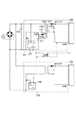
しかしながら、特許文献1の電源装置では、前述のように制御系電源が駆動系電源より先に停止してしまう場合がある。特許文献1の電源装置は制御ICによって動作を制御しており、この制御ICを駆動するための電圧を供給する必要がある。具体的に図10を用いて説明する。図10は主要部を抜粋したものであり101は制御系電源であり、102は駆動系電源である。200は制御部であり、300は駆動系の負荷である。103は制御系電源101と駆動系電源102のための平滑コンデンサである。107は制御系電源101を制御する制御ICであり、108は駆動系電源102を制御する制御ICである。また、制御系電源101のトランス109の主巻線109pに対して巻方向が異なる方向に巻いた(以降、フライバック結合と呼ぶ)補助巻線109cを有する。この補助巻線109cに誘起されるパルス電圧をダイオード110とコンデンサ111で整流平滑した電圧Vcc3を制御IC107及び制御IC108の駆動電圧として使用する。
However, in the power supply device of
ここで補助巻線109cに誘起される電圧Vddは、図10の制御系電源101の出力電圧Vout11、ダイオード112の順方向電圧をVfd、ニ次巻線109sの巻き数をNss、補助巻線109cの巻き数をNddとすると、概ね次式(1)で表される。
Here, the voltage Vdd induced in the auxiliary winding 109c is the output voltage Vout11 of the control

電圧Vddは、ダイオード110とコンデンサ111によって整流及び平滑され、制御IC107及び制御IC108の電源電圧Vcc3として供給される。制御IC107及び制御IC108は、電源電圧Vcc3によってスイッチング動作を制御する。なお、このとき、ダイオード110の順方向電圧をVfd2とすると、電源電圧Vcc3は概ね次式(2)で表される。
The voltage Vdd is rectified and smoothed by the
![]()
![]()
よって、整流及び平滑された電源電圧Vcc3は、制御系電源101の出力電圧Vout11に略比例した電圧となる。
Therefore, the rectified and smoothed power supply voltage Vcc3 is a voltage substantially proportional to the output voltage Vout11 of the control
特許文献1の電源装置において電子機器の動作中に停電や電源ケーブルが抜かれた際は、(2)式で示される通り、制御系電源101の出力電圧Vout11が低下するまで制御IC108の電源電圧Vcc3は低下しない。制御系電源101の出力電圧Vout11が低下して初めて駆動系電源102の制御IC108の電源電圧Vcc3も低下する。しかし電源電圧Vcc3が低下しても、すぐに制御IC108は停止することはなく動作を継続できるため駆動系電源102は出力電圧Vout22を維持する。よって制御系電源101の出力電圧Vout11が先に低下し、駆動系電源102がVout22を出力している間でモータの制御が正しく行えない状態でモータへの電力供給が継続され、その間モータが意図しない回転を続けてしまう。またはモータが突如動き出してしまう等の意図しない動作が生じる可能性がある。
When a power failure or a power cable is disconnected during the operation of the electronic device in the power supply device of
本発明は、前述課題を解決するためになされたものであり、電子機器の動作中に商用電源の交流電圧が低下又は停止した際に制御系電源より先に駆動系電源を停止させ、駆動系の負荷が意図しない動作を行わないようにすること目的とする。 The present invention has been made to solve the above-mentioned problems, and when the AC voltage of the commercial power supply is reduced or stopped during the operation of the electronic device, the drive system power supply is stopped before the control system power supply. The purpose of this is to prevent unintended operations from being performed by the load.
上記課題を解決するための本発明の電源装置は、入力される交流電圧を整流及び平滑した電圧が供給される第一のトランスを有し、前記第一のトランスをスイッチングすることにより第一の直流電圧を出力する第一のスイッチング電源と、前記第一のスイッチング電源のスイッチング動作を制御する第一の制御手段と、前記交流電圧を整流及び平滑した電圧が入力される第二のトランスを有し、前記第二のトランスをスイッチングすることにより第二の直流電圧を出力する第二のスイッチング電源と、前記第二のスイッチング電源のスイッチング動作を制御する第二の制御手段と、を有する電源装置において、前記第一のトランスの一次巻線と、前記一次巻線と巻方向が同一の第一の補助巻線と、前記一次巻線と巻方向が同一であって前記第一の補助巻線よりも巻き数が少ない第二の補助巻線と、前記第一の補助巻線に接続されており前記第一の制御手段を動作させるために前記第一の制御手段に供給される電源電圧を生成する第一の電圧生成手段と、前記第二の補助巻線に接続されており前記第二の制御手段を動作させるために前記第二の制御手段に供給される電源電圧を生成する第二の電圧生成手段と、を有し、前記第一の電圧生成手段により生成される電源電圧よりも前記第二の電圧生成手段により生成される電源電圧が小さくなるように電源電圧が生成され、前記交流電圧が停止した際に、前記電圧生成手段が生成する電圧に従って、前記第一の制御手段よりも前記第二の制御手段が先に停止するように制御することを特徴とする。 A power supply apparatus of the present invention for solving the above-described problem has a first transformer to which a voltage obtained by rectifying and smoothing an input AC voltage is supplied, and the first transformer is switched by switching the first transformer. A first switching power supply that outputs a DC voltage; first control means that controls a switching operation of the first switching power supply; and a second transformer that receives a voltage obtained by rectifying and smoothing the AC voltage. And a second switching power source that outputs a second DC voltage by switching the second transformer, and a second control unit that controls a switching operation of the second switching power source. in the the first transformer primary winding, said primary winding and the winding direction the same as the first auxiliary winding, the primary winding and winding direction are identical first And the auxiliary winding second auxiliary winding has fewer windings than is supplied to the first control means to operate said first is connected to the auxiliary winding said first control means A first voltage generating means for generating a power supply voltage, and a power supply voltage connected to the second auxiliary winding and supplied to the second control means for operating the second control means. has a second voltage generating means for generating, wherein the first voltage supply voltage so that the power supply voltage decreases generated by said second voltage generating means than the power supply voltage generated by the generating means is generated, when the AC voltage is stopped, in accordance with a voltage by the voltage generating means for generating, said than the first control means a second control means and controls to stop earlier .
また、本発明の画像形成装置は、記録材に画像を形成する画像形成装置において、画像形成手段と、前記画像形成装置に電力を供給する電源装置とを有し、前記電源装置は、入力される交流電圧を整流及び平滑した電圧が供給される第一のトランスを有し、前記第一のトランスをスイッチングすることにより第一の直流電圧を出力する第一のスイッチング電源と、前記第一のスイッチング電源のスイッチング動作を制御する第一の制御手段と、前記交流電圧を整流及び平滑した電圧が入力される第二のトランスを有し、前記第二のトランスをスイッチングすることにより第二の直流電圧を出力する第二のスイッチング電源と、前記第二のスイッチング電源のスイッチング動作を制御する第二の制御手段と、前記第一のトランスの一次巻線と、前記一次巻線と巻方向が同一の第一の補助巻線と、前記一次巻線と巻方向が同一の第一の補助巻線と、前記一次巻線と巻方向が同一であって前記第一の補助巻線よりも巻き数が少ない第二の補助巻線と、前記第一の補助巻線に接続されており前記第一の制御手段を動作させるために前記第一の制御手段に供給される電源電圧を生成する第一の電圧生成手段と、前記第二の補助巻線に接続されており前記第二の制御手段を動作させるために前記第二の制御手段に供給される電源電圧を生成する第二の電圧生成手段と、を有し、前記第一の電圧生成手段により生成される電源電圧よりも前記第二の電圧生成手段により生成される電源電圧が小さくなるように電源電圧が生成され、前記交流電圧が停止した際に、前記電圧生成手段が生成する電圧に従って、前記第一の制御手段よりも前記第二の制御手段が先に停止するように制御することを特徴とする。 The image forming apparatus of the present invention is an image forming apparatus that forms an image on a recording material. The image forming apparatus includes an image forming unit and a power supply device that supplies power to the image forming device. A first transformer that is supplied with a voltage obtained by rectifying and smoothing the AC voltage, and switching the first transformer to output a first DC voltage; and A first control means for controlling a switching operation of the switching power supply; and a second transformer into which a voltage obtained by rectifying and smoothing the AC voltage is input, and the second DC is switched by switching the second transformer. A second switching power supply that outputs a voltage; a second control means that controls a switching operation of the second switching power supply; and a primary winding of the first transformer; Serial and primary winding and the winding direction the first auxiliary winding same, wherein the primary winding and the winding direction the same as the first auxiliary winding, the primary winding and winding direction are identical first supplied to the first control means to operate a second auxiliary winding has fewer windings than the first auxiliary winding, the first being connected to the auxiliary winding said first control means A first voltage generating means for generating a power supply voltage to be supplied, and a power supply voltage connected to the second auxiliary winding and supplied to the second control means for operating the second control means And a second voltage generating means for generating the power supply voltage so that the power supply voltage generated by the second voltage generating means is smaller than the power supply voltage generated by the first voltage generating means. There are generated, when the AC voltage is stopped, the voltage by the voltage generating means for generating What, said second control means than said first control means and controls to stop earlier.
以上説明したように、本発明によれば、電子機器の動作中に商用電源の交流電圧が低下又は停止した際に制御系電源より先に駆動系電源を停止させ、駆動系の負荷が意図しない動作を行わないようにすることができる。 As described above, according to the present invention, when the AC voltage of the commercial power supply decreases or stops during operation of the electronic device, the drive system power supply is stopped before the control system power supply, and the drive system load is not intended. It is possible not to perform the operation.
以下に、図面を参照して、この発明の好適な実施の形態を例示的に詳しく説明する。ただし、この実施の形態に記載されている構成要素はあくまで例示であり、この発明の範囲をそれらのみに限定する趣旨のものではない。 Hereinafter, exemplary embodiments of the present invention will be described in detail with reference to the drawings. However, the constituent elements described in this embodiment are merely examples, and are not intended to limit the scope of the present invention only to them.
(本発明のスイッチング電源が適用される装置の一例)
以下の実施例1乃至5で説明するスイッチング電源は、例えば画像形成装置の低圧電源、即ち画像形成動作を制御するコントローラ(制御部)やモータ等の駆動部へ電力を供給する電源として適用可能である。まず、実施例1乃至5のスイッチング電源が適用される画像形成装置の構成を説明する。なお、本発明のスイッチング電源は画像形成装置に限らず制御系負荷と駆動系負荷を有する装置に適用可能である。
(Example of apparatus to which switching power supply of the present invention is applied)
The switching power supply described in the following first to fifth embodiments can be applied as, for example, a low-voltage power supply for an image forming apparatus, that is, a power supply that supplies power to a controller (control unit) that controls an image forming operation or a driving unit such as a motor. is there. First, the configuration of the image forming apparatus to which the switching power supply according to the first to fifth embodiments is applied will be described. The switching power supply of the present invention is not limited to an image forming apparatus, and can be applied to an apparatus having a control system load and a drive system load.
[画像形成装置の構成]
画像形成装置の一例として、図9に電子写真方式のプリンタの一例であるレーザビームプリンタの概略構成を示す。レーザビームプリンタ500は、静電潜像が形成される像担持体としての感光ドラム511を備えている。そして、感光ドラム511の表面を一様に帯電する帯電部517(帯電手段)、感光ドラム511に形成された静電潜像をトナーで現像する現像部512(現像手段)を備えている。そして、感光ドラム511に現像されたトナー像をカセット516から供給された記録材としてのシート(不図示)に転写部518(転写手段)によって転写して、シートに転写したトナー像を定着器514で定着してトレイ515に排出する。この感光ドラム511、帯電部517、現像部512、転写部518が画像形成部である。また、レーザビームプリンタ500は、以降で説明する実施例1乃至5で説明する電源装置550を備えている。なお、実施例1乃至5の電源装置550を適用可能な画像形成装置は、図9に例示した構成に限定されず、例えば、夫々、色の異なる画像を形成可能な複数の画像形成部を備えるカラー画像形成装置であってもよい。カラー画像形成装置としては、例えば、感光ドラム511上のトナー像を中間転写ベルトに転写する一次転写部と、中間転写ベルト上のトナー像をシートに転写する二次転写部を備える装置であってもよい。
[Configuration of Image Forming Apparatus]
As an example of the image forming apparatus, FIG. 9 shows a schematic configuration of a laser beam printer which is an example of an electrophotographic printer. The
レーザビームプリンタ500は、画像形成部による画像形成動作や、シートの搬送動作を制御するコントローラ520を備えており、以降で説明する実施例1乃至5に記載の電源装置550は、例えばコントローラ520に電力を供給する。また、実施例1乃至5に記載の電源装置550は、感光ドラム511を回転するため、又はシートを搬送する各種ローラ等を駆動するためのモータ等の駆動部に電力を供給する。
The
図1は、実施例1の電源装置の構成を示す回路図である。この回路は、CPUやASIC等の動作に必要な電圧が低い制御系負荷への第一の直流電圧Vout1と、モータやソレノイド等の動作に必要な電圧が高い駆動系負荷への第二の直流電圧Vout2との2系統の電圧を供給する2コンバータ構成の回路である。 FIG. 1 is a circuit diagram illustrating a configuration of the power supply device according to the first embodiment. This circuit includes a first DC voltage Vout1 to a control system load having a low voltage required for the operation of a CPU, an ASIC, etc., and a second DC voltage to a drive system load having a high voltage required for the operation of a motor, a solenoid or the like. It is a circuit of a two-converter configuration that supplies two systems of voltages, the voltage Vout2.
一般に、第一の直流電圧Vout1は、第二の直流電圧Vout2よりも低く設定される。例えば、Vout1=DC3.3Vに対して、Vout2=DC24Vという設定や、Vout1=DC1.8Vに対して、Vout2=DC12Vといった設定が一般的である。 In general, the first DC voltage Vout1 is set lower than the second DC voltage Vout2. For example, Vout1 = DC3.3V is generally set to Vout2 = DC24V, and Vout1 = DC1.8V is set to Vout2 = DC12V.
以降では、Vout1=DC3.3Vに対してVout2=DC24Vの設定を例として、説明を行う。だたし、このDC電圧の値は一例であって、種々供給する負荷に必要な電圧を選定すればよい。 Hereinafter, the setting of Vout2 = DC24V with respect to Vout1 = DC3.3V will be described as an example. However, the value of the DC voltage is an example, and a voltage necessary for various loads to be supplied may be selected.
また、本実施例の画像形成装置は商用電源の低下を検知する回路(不図示)を有しており、商用電源の停電や電源ケーブルを抜かれたことによって交流電圧が低下したことを検出することができる。なお、商用電源の交流電圧の低下又は停止を検知する回路とは、例えば、交流電圧が0Vを横切るポイント(ゼロクロスポイントと呼ぶ)を検出する回路(ゼロクロス回路)がある。その他に、交流電圧の周波数を検出する回路がある。交流電圧の周波数を検知する回路は、画像形成装置における定着器への投入電力の制御にも使用される。このような交流電圧の周波数を検出する回路は、所定の時間波形が検出できない場合に停電である検出することができる。停電であると検出した場合は、CPUやASIC等の制御部はモータ等の駆動系負荷及び不図示の他の回路に対して所定の終了処理を行うように制御する。 In addition, the image forming apparatus according to the present exemplary embodiment includes a circuit (not illustrated) that detects a drop in commercial power, and detects that the AC voltage has dropped due to a power failure or disconnection of the power cable. Can do. Note that the circuit that detects a drop or stop of the AC voltage of the commercial power supply includes, for example, a circuit (zero cross circuit) that detects a point where the AC voltage crosses 0V (referred to as a zero cross point). In addition, there is a circuit for detecting the frequency of the AC voltage. The circuit for detecting the frequency of the AC voltage is also used for controlling the input power to the fixing device in the image forming apparatus. Such a circuit that detects the frequency of the AC voltage can detect a power failure when a predetermined time waveform cannot be detected. When it is detected that there is a power failure, a control unit such as a CPU or ASIC controls a drive system load such as a motor and other circuits not shown to perform predetermined termination processing.
図1において、20は制御系負荷に直流電圧Vout1を供給する第一のスイッチング電源(以降、制御系電源と呼ぶ)、60は駆動系負荷に直流電圧Vout2を供給する第二のスイッチング電源(以降、駆動系電源と呼ぶ)である。また70は制御系電源20の負荷であり、装置の動作を制御するためのコントローラ、ASIC等の制御部である。80は駆動系電源60の負荷(駆動系負荷)であり、装置を駆動するためのモータやソレノイド等の負荷である。また、24b、ダイオード25、コンデンサ26、ツェナーダイオード30は本実施例における制御ICの電源電圧を生成する電圧生成回路である。
In FIG. 1, 20 is a first switching power supply (hereinafter referred to as a control system power supply) that supplies a DC voltage Vout1 to a control system load, and 60 is a second switching power supply (hereinafter referred to as a control system power supply). , Referred to as drive system power supply).
まず、制御系電源20の動作を説明する。商用電源10から交流電圧が印加されると、整流器11で整流された電圧が蓄電手段であるコンデンサ13に充電される。コンデンサ13への充電が開始され、コンデンサ13の端子間電圧が上昇すると起動抵抗21を介して第一の制御手段である制御IC22のVH端子に電源電圧が供給され、制御IC22はOUT端子よりFET23をオンしてスイッチング動作を開始する。ここで、トランス24は一次巻線24pの他に、二次巻線24s及び補助巻線24bが巻かれている。二次巻線24sは、一次巻線24pに対して巻方向が逆方向となるよう構成されている。一方、補助巻線24bは、一次巻線24pに対して巻方向が同一の方向(以降、フォワード結合と呼ぶ)となるよう構成される。FET23がオンするとコンデンサ13からトランス24の一次巻線24pに電流が流れ、この電流により発生する磁束によってエネルギーの蓄積を行う。この時、二次巻線24sに現れる電圧はダイオード31のアノード側を負とする電圧であるため電流が流れない。また、補助巻線24bに現れる電圧はダイオード25を通じてコンデンサ26を充電する方向に電流が流れ、コンデンサ26の電圧が上昇する。コンデンサ26の電圧が上昇すると、制御IC22は、起動抵抗21から供給されていた電源電圧を、VCC端子に接続されたコンデンサ26から供給されるように内部で切り替える。このように切り換えるのは、起動抵抗21から電源電圧を消費する状態は損失が大きく、効率を低下させてしまうためである。ここで補助巻線24bに誘起される電圧Vbは、コンデンサ13の電圧をVh、一次巻線24pの巻き数をNp、補助巻線24bの巻き数をNbとすると、概ね次式(3)で表される。
First, the operation of the control
このVbは、ダイオード25とコンデンサ26によって整流及び平滑され、制御IC22に電源電圧Vcc1として供給される。これ以降、制御IC22は、この電源電圧Vcc1によって動作を継続する。なお、このとき、ダイオード25の順方向電圧をVfとすると、Vcc1は概ね次式(4)で表される。
This Vb is rectified and smoothed by the
よって、整流及び平滑された電源電圧Vcc1は、コンデンサ13の電圧Vhに略比例した電圧となる。
Therefore, the rectified and smoothed power supply voltage Vcc1 is a voltage that is substantially proportional to the voltage Vh of the
トランス24の一次巻線24pに流れる電流は抵抗28によって電圧に変換され、制御IC22のIS端子に供給される。制御IC22はIS端子に入力された電圧がFB端子に入力された電圧になった時点でFET23をオフする。すると一次巻線24pのFET23のドレイン側端子の電圧が上昇する。また二次巻線24sに現れる電圧はダイオード31のアノード側を正とする電圧が現れ、トランス24に蓄積されたエネルギーが放出される。そしてダイオード31を通じてコンデンサ32を充電する方向に電流が流れ、コンデンサ32の電圧が上昇する。本実施例ではPWM制御を行う制御ICを採用しており、制御IC22は、FB端子電圧に応じたスイッチング周波数で動作するようにFET23をオンする。FET23がオンされると、再度トランス24の一次巻線24pを介して電流が流れる。この様に制御IC22は、FET23のオン、オフを繰り返し、次第にコンデンサ32およびコンデンサ26の電圧を上昇させる。コンデンサ32の電圧は、制御系電源20の出力電圧Vout1である。
The current flowing through the primary winding 24p of the
シャントレギュレータ35のRef端子には制御系電源20の出力電圧Vout1を抵抗33と34によって分圧した電圧が入力されるように接続される。また、シャントレギュレータ35のカソード端子は抵抗38を介してフォトカプラの発光ダイオード39に接続され、フォトカプラのフォトトランジスタ27は制御IC22のFB端子に接続される。制御IC22のFB端子の電圧は、制御IC22より放出されるFB端子に流れる電流と、二次側のフィードバック回路及びフォトトランジスタ27の動作に応じて変化する。制御系電源20の出力電圧が低下するとシャントレギュレータ35の出力電流は小さくなるため、発光ダイオード39の発光量は減り、フォトトランジスタ27に流れる電流が低下する。よって制御IC22内部の電源によりコンデンサ29が充電されてFB端子の電圧は上昇する。この時、制御IC22は、IS端子の電圧がFB端子電圧になった時点でFET23をオフするため、FB端子の電圧が上昇するとFET23のオン時間が長くなる。また、これと逆に制御系電源20の出力電圧が上昇すると、フォトトランジスタ27に流れる電流が増加し、コンデンサ29の電荷が放電されFB端子の電圧は低下する。この時、制御IC22は、IS端子の電圧がFB端子の電圧になった時点でFET23をオフするため、FB端子の電圧が低下するとオン時間が短くなる。このように制御IC22は、シャントレギュレータ35の基準電圧Vrefと制御系電源20の出力電圧Vout1を抵抗33と34で分圧した電圧が等しくなるようにFET23のオン時間を制御する。これにより、出力電圧を安定した第一の直流電圧Vout1にする。
The Ref terminal of the
次に、駆動系電源60の動作を説明する。本実施例の駆動系電源60は、制御系電源20と同じ制御IC40を用いているため、制御系電源20と同じ機能及び動作の箇所は、例えばトランスの構成、フォトカプラ等については符号及び説明を省略する。
Next, the operation of the drive
駆動系電源60の制御IC40のVcc端子への電圧の供給/停止は、制御部70により制御され、制御IC40の動作/停止が制御される。制御部70より動作開始信号が出力されると抵抗42を介してフォトカプラ43の発光ダイオードに電流が流れる。するとフォトカプラ43のフォトトランジスタがオンし、抵抗44を介してトランジスタ45へのベース電流が供給されトランジスタ45がオンする。そして、トランジスタ45がオンすると、前述(4)式で示された制御系電源20の電圧Vcc1がツェナーダイオード30を介して制御IC40の電源電圧Vcc2として供給される。このとき、ツェナーダイオード30のツェナー電圧をVzとすると、Vcc2は概ね次式(5)で表わされる。
Supply / stop of the voltage to the Vcc terminal of the
よって、整流及び平滑された電圧Vcc2は、コンデンサ13の電圧Vhに略比例した電圧となる。
Therefore, the rectified and smoothed voltage Vcc2 is a voltage substantially proportional to the voltage Vh of the
以上説明したように、(4)式及び(5)式から、制御IC22の電源電圧Vcc1と制御IC40の電源電圧Vcc2にはVz分の電圧差をつけており、Vcc1>Vcc2の関係にすることが本実施例の特徴である。制御IC40は、電圧Vcc2が供給されるとスイッチング動作を開始する。以降は制御系電源20と同様の動作で出力電圧を安定した第二の直流電圧Vout2にする。
As described above, from the equations (4) and (5), the power supply voltage Vcc1 of the
次に、本実施例の構成における、定常状態から停電、又は電源ケーブルが抜かれた際の各電圧の遷移を図2を用いて説明する。ここで、本実施例の効果を従来例と比較するため、図10で説明した電源装置の回路において、補助巻線109cをトランス109の一次巻線109pに対してフライバック結合となるよう構成された場合の電圧の遷移も合わせて説明する。
Next, transition of each voltage when the power failure or the power cable is disconnected from the steady state in the configuration of the present embodiment will be described with reference to FIG. Here, in order to compare the effect of the present embodiment with the conventional example, the auxiliary winding 109c is configured to be flyback coupled to the primary winding 109p of the
まず、図2(A)を用いて本実施例の電子機器の待機中である駆動系負荷80の負荷が比較的小さい場合において、停電又はコンセントが抜かれる等で交流電圧が低下した時の電圧波形の遷移と電源装置の動作を説明する。時刻t0以前は、交流電圧が供給された状態でありコンデンサ13の電圧Vhは安定した電圧を保持しており、制御系電源20と駆動系電源60は通常動作を行っている。よって出力電圧Vout1及びVout2も安定した電圧で推移する。時刻t0で例えば、停電が発生すると、商用電源10からの交流電圧の供給がなくなるためコンデンサ13の電圧Vhは低下する。そして、それと共に(4)式、(5)式で示したように電圧Vhと略比例した関係である制御IC22の電源電圧Vcc1と制御IC40の電源電圧Vcc2も低下し始める。なお、電源電圧Vcc1及びVcc2は(5)式で示したようにツェナーダイオード30のツェナー電圧Vz分の電圧差が生じている。また、t0からt1の間は制御IC22と制御IC40は制御を継続することが可能なため、スイッチング動作を継続しており出力電圧Vout1とVout2は出力し続ける。時刻t1の時点でVcc2が制御IC40の動作停止電圧Vstに達するため、駆動系電源60が先に停止し出力電圧Vout2が低下し始める。その後、時刻t2で電源電圧Vcc1が制御IC22の動作停止電圧Vstに達するため、制御系電源20が停止し出力電圧Vout1が低下する。
First, referring to FIG. 2A, when the load of the
次に図2(B)を用いて従来の電源装置における停電、又は電源ケーブルが抜かれた際の各電圧の遷移を説明する。時刻t0以前は図2(A)と同様に交流電圧が供給された状態でありコンデンサ103の電圧は安定した電圧を保持しており、制御系電源101と駆動系電源102は通常動作を行っている。よって出力電圧Vout11及びVout22も安定した電圧で推移する。時刻t0で、例えば停電が発生すると、商用電源10からの交流電圧の供給がなくなるためコンデンサ103の電圧は低下する。またt0からt1の間において制御IC107と制御IC108は制御を継続することが可能なため、動作を継続し出力電圧Vout11とVout22は出力し続ける。よってt0からt1の間において制御IC107と制御IC108の電源電圧Vcc3は、(2)式で示したように出力電圧Vout11と略比例関係であるため、図2(A)とは異なり低下しない。そして、時刻t1の時点でのコンデンサ103に蓄えられている電力では出力電圧Vout11を維持できなくなるため、Vout11の低下が始まり、Vout11と略比例関係でVcc3の低下も始まる。待機中であるため駆動軽負荷300は動作しておらず、ほとんど電力を消費しない。一方、制御系電源101は制御部200への電力供給しているため、駆動系電源102よりも制御系電源101のほうが先に出力電圧Vout11は低下する。時刻t2で制御部200の電源電圧が低下し、制御部200が動作停止となると駆動系電源102の駆動信号が出力されなくなる。よって制御IC108のVcc3が供給されなくなり、駆動系電源102は停止し、出力電圧Vout22は低下する。時刻t2以降は制御部200が動作停止状態で、且つ出力電圧Vout22の出力電圧がある程度高い状態になる。この状態は駆動軽負荷300が動作できる状態であり、前述したようにモータやソレノイド等が突如動き出してしまうような意図しない動作が生じてしまう可能性がある。これに対して、図2(A)で説明したように、本実施例の電源装置は、先に駆動系電源60が停止する構成であり、制御部70が動作停止となる際は、駆動系負荷80への供給電圧が低下しておりモータやソレノイドが意図せず動作することはない。
Next, the transition of each voltage when a power failure in the conventional power supply device or the power cable is disconnected will be described with reference to FIG. Prior to time t0, an AC voltage is supplied as in FIG. 2A, and the voltage of the
以上説明したように、電子機器の動作中に停電が発生したり、又、電源ケーブルが抜かれた際に制御系電源20より先に駆動系電源60を停止させることが可能となる。なお、本実施例における電圧生成手段では、電源電圧Vcc1及びVcc2に電位差を持たせるためにツェナーダイオードを使用した回路を示した。しかしながら、これに限定されるものではなく、例えば、電位差を設ける他の構成としては、電源電圧Vcc1からシリーズレギュレータやシャントレギュレータを用いて電源電圧Vcc2を生成するように回路を構成してもよい。
As described above, it is possible to stop the drive
実施例1で述べた図1のスイッチング電源において、駆動系負荷80が動作中の重負荷時にも停電等で交流電力の供給が断たれる場合がある。このとき、駆動系電源60は駆動軽負荷80を駆動するために、しばらくはコンデンサ13の電気エネルギーによって電力供給を継続する。すると、コンデンサ13に蓄えられた電気エネルギーが駆動系電源60で使用されてしまうため、制御系電源20が停止するまでの時間が短くなる。本実施例は、駆動系電源60が重負荷時に停電が発生した場合でも、制御系電源20が停止するまでの時間を駆動系電源60が軽負荷の場合と同等にすること特徴とする。
In the switching power supply of FIG. 1 described in the first embodiment, the supply of AC power may be interrupted due to a power failure or the like even when the
図3に実施例2の電源装置を示す。前述した図1で説明した電源装置と同様の構成については、同じ符号を付して説明を省略する。また、図4に実施例2のスイッチング電源の特徴を表す動作波形を示す。図3の構成は、整流平滑回路において本実施例の逆流防止手段であるダイオード12と駆動系電源60用のコンデンサ41を配置した構成が実施例1(図1)とは異なる。すなわち、本実施例では制御系電源20と駆動系電源60に対して、整流平滑用コンデンサを独立して配置し、制御系電源20のコンデンサ13に蓄えられた電気エネルギーが駆動系電源60のコンデンサ41に逆流しないようにした構成が特徴である。
FIG. 3 shows a power supply device according to the second embodiment. The same components as those of the power supply device described with reference to FIG. FIG. 4 shows operation waveforms representing the characteristics of the switching power supply according to the second embodiment. The configuration of FIG. 3 is different from that of the first embodiment (FIG. 1) in that a
図3において商用電源10から交流電圧が印加されると、整流器11で整流された電圧がダイオード12を介してコンデンサ13が充電される。コンデンサ13の端子間電圧が上昇すると起動抵抗21を介して制御IC22のVH端子に電源が供給され、制御IC22はOUT端子よりFET23をオンし、スイッチングを開始する。以降は実施例1と同様の動作により、制御系電源20は出力電圧を安定した第一の直流電圧Vout1にする。
In FIG. 3, when an AC voltage is applied from the
また、商用電源10から交流電圧が印加されると、整流器11で整流された電圧によってコンデンサ41が充電される。制御部70より動作開始信号が出力されると制御IC40に電源電圧Vcc2が供給され、制御IC40はスイッチングを開始する。以降は制御系電源20と同様の動作で駆動系電源60は出力電圧を安定した第二の直流電圧Vout2にする。
When an AC voltage is applied from the
次に、図4に基づき本実施例の動作を説明する。なお実施例1と同様な箇所は説明を省略する。まず、図4(A)を用いて本実施例の停電時の電圧波形の遷移と電源装置の動作を説明する。時刻t0以前は、実線で示されるコンデンサ13の電圧Vh及び破線で示されるコンデンサ41の電圧Vh2は安定した電圧を保持しており、電圧Vh2は、ダイオード12の順方向電圧をVf12とすると次式(6)の関係となっている。
Next, the operation of this embodiment will be described with reference to FIG. Note that description of parts similar to those in the first embodiment is omitted. First, the transition of the voltage waveform and the operation of the power supply device during a power failure according to this embodiment will be described with reference to FIG. Prior to time t0, the voltage Vh of the
Vh2=Vh+Vf12 ・・・(6)
時刻t0で停電が発生すると、コンデンサ13の電圧Vh及びコンデンサ41の電圧Vh2は商用電源からの電荷供給がなくなるため低下し始める。駆動系電源60が重負荷の場合は、コンデンサ41に蓄えられている電気エネルギーを駆動軽負荷80へ放出する量が大きく、かつ商用電源からの電気エネルギーの供給もない。そのため、コンデンサ41の電圧Vh2の電圧は図3(A)の破線で示す通り急速に低下する。一方コンデンサ13の電圧Vhはダイオード12によって電気エネルギーがコンデンサ41に逆流しないため、急速に低下することはなく実線で示す低下となる。そして、電圧Vhの低下と共に(4)式(5)式で示されるようにVhと略比例関係である制御IC22のVcc1と制御IC40のVcc2も低下し始める。また、t0からt1の間は制御IC22と制御IC40は制御を継続することが可能なため、動作を継続し出力電圧Vout1とVout2は出力し続ける。時刻t1の時点でVcc2が制御IC40の動作停止電圧Vstに達するため、駆動系電源60が先に停止し出力電圧Vout2が低下し始める。その後時刻t2でVcc1が制御IC22の動作停止電圧Vstに達するため、制御系電源20が停止し出力電圧Vout1が低下する。本実施例では逆流防止用のダイオード12があることで、駆動系電源60が重負荷であっても軽負荷であってもコンデンサ13の電圧Vhの低下する傾きはほぼ変わらない。よって停電が発生してから制御IC22が停止するまでの時刻t2は、駆動系電源60の駆動軽負荷80の状態によらずほぼ一定である。
Vh2 = Vh + Vf12 (6)
When a power failure occurs at time t0, the voltage Vh of the
次に本実施例の効果を説明するため、図4(B)を用いて、実施例1の構成における駆動系電源60が重負荷の場合の動作波形と比較する。時刻t0以前は、実施例2と同様にコンデンサ13の電圧Vhは安定した電圧を保持しており、制御系電源20と駆動系電源60は通常動作を行い、出力電圧Vout1及びVout2は安定した電圧で推移する。時刻t0で停電が発生すると、駆動系電源60が重負荷の場合は、コンデンサ13に蓄えられている電気エネルギーを駆動系負荷80へ放出する量が大きく、かつ商用電源からの電気エネルギーの供給もない状態である。そのため、電圧Vhの電圧は図4(B)で示す通り急速に低下する。電圧Vhの低下と共にVhと略比例関係である制御IC22のVcc1と制御IC40のVcc2は低下する。時刻t1の時点でVcc2が制御IC40の動作停止電圧Vstに達すると、駆動系電源60が先に停止し出力電圧Vout2が低下する。その後、時刻t2でVcc1が制御IC22の動作停止電圧Vstに達すると、制御系電源20が停止し出力電圧Vout1が低下する。このように、駆動系電源60が重負荷の場合は、停電後の駆動軽負荷への電力供給によってコンデンサ13の電圧Vhが急速に低下する。よって停電が発生した時刻t0から制御IC40が動作停止電圧に達するまでの時刻t1は、図4(A)に比べて短くなるため、その後、制御IC22の動作停止電圧Vstに達し、出力電圧Vout11が低下する時刻t2も短くなってしまう。
Next, in order to explain the effect of the present embodiment, FIG. 4B is used to compare with the operation waveform when the drive
以上説明したように、本実施例は、駆動系電源60の負荷状態に関わらず、電子機器の動作中に停電が発生したり、電源ケーブルが抜かれた際に制御系電源20が所定の処理を完了するまでの時間を確保することが可能となる。よって、不図示の商用電源の低下を検知する回路により、駆動系電源60の駆動軽負荷80の動作中であっても、制御部70の機能が停止する前に駆動軽負荷80の動作終了処理を完了することができる。
As described above, in this embodiment, regardless of the load state of the drive
図5に実施例3の電源装置を示す。前述した図1及び図3で説明した電源装置と同様の構成については、同じ符号を付して説明を省略する。また、図6に、実施例3のスイッチング電源の特徴を表す動作波形を示す。 FIG. 5 shows a power supply device according to the third embodiment. The same components as those of the power supply device described with reference to FIGS. 1 and 3 described above are denoted by the same reference numerals and description thereof is omitted. FIG. 6 shows operation waveforms representing the characteristics of the switching power supply according to the third embodiment.
本実施例では、図5で示す制御系電源20の制御IC22と駆動系電源60の制御IC40は動作停止電圧の異なるICを採用している。具体的には制御IC22の動作停止電圧をVst1とすると、Vst1=6.5Vであり、制御IC40の動作停止電圧をVst2とすると、Vst2=9Vであり、Vst1<Vst2となる制御ICの組み合わせであることが特徴である。またツェナーダイオード30を削除したところが実施例2(図3)とは異なる。よって、制御系電源20の制御IC22と、駆動系電源60の制御IC40へ供給電圧Vcc1はほぼ同じ電圧となる。
In this embodiment, the
まず、制御系電源20の動作を説明する。商用電源10から交流電圧が印加されると、整流器11で整流された電圧がダイオード12を介してコンデンサ13が充電される。コンデンサ13の端子間電圧が上昇すると起動抵抗21を介して制御IC22のVH端子に電源が供給され、制御IC22はOUT端子よりFET23をオンし、スイッチングを開始する。以降は実施例1と同様の動作により、制御系電源20は出力電圧を安定した第一の直流電圧Vout1にする。
First, the operation of the control
次に、駆動系電源60の動作を説明する。本実施例では駆動系電源60はフォワード方式のスイッチング電源である。商用電源10から交流電圧が印加されると、整流器11で整流された電圧によってコンデンサ41が充電される。制御部70より動作開始信号が出力されると制御IC40に電源電圧Vcc1が供給され、制御IC40はFET46をオンしスイッチングを開始する。ここで、トランス47は一次巻線47pの他に、二次巻線47sが巻かれている。二次巻線47sは、一次巻線47pに対して巻方向が同じ方向となるよう構成されている。トランス47の二次巻線47sから発生するパルス電圧は、ダイオード48及び49、チョークコイル50、コンデンサ51よりなるフォワード型の整流平滑回路にて整流平滑し直流電圧Vout2を得る。この出力電圧Vout2が所望の値になるように、シャントレギュレータ52のRef端子には駆動系電源60の出力電圧Vout2を抵抗53,54によって分圧した電圧が接続される。そして、シャントレギュレータ52のカソード端子は抵抗55を介してフォトカプラの発光ダイオード56に接続され、フォトカプラのフォトトランジスタ57は制御IC40のFB端子に接続されている。制御IC40のFB端子電圧は、制御IC40より放出されるFB端子電流と、二次側フィードバック回路およびフォトトランジスタ57の動作に応じて変化する。このFB電圧の変化が、FET46のスイッチングデューティや、スイッチング周波数を変化させる主なトリガーとなり、安定した出力電圧Vout2の制御が可能となる。
Next, the operation of the drive
次に、図6に基づき本実施例の動作を説明する。なお実施例1と同様な箇所は説明を省略する。まず、図6を用いて本実施例の停電時の電圧波形の遷移と電源装置の動作を説明する。時刻t0以前は、実線で示されるコンデンサ13の電圧Vhは安定した電圧を保持しており、制御系電源20と駆動系電源60は通常動作を行っている。よって出力電圧Vout1及びVout2も安定した電圧で推移する。時刻t0で停電が発生すると、商用電源からの電荷供給がなくなるためコンデンサ13の電圧Vhは低下し、それと共に(4)式で示されるように電圧Vhと略比例関係である制御IC22と制御IC40のVcc1も低下し始める。また、t0からt1の間は制御IC22と制御IC40は制御を継続することが可能なため、動作を継続し出力電圧Vout1とVout2は出力し続ける。時刻t1の時点でVcc1が制御IC40の動作停止電圧Vst2=9Vに達するため、駆動系電源60が先に停止し出力電圧Vout2が低下し始める。その後時刻t2でVcc1が制御IC22の動作停止電圧Vst1=6.5Vに達するため、制御系電源20が停止し出力電圧Vout1が低下する。
Next, the operation of this embodiment will be described with reference to FIG. Note that description of parts similar to those in the first embodiment is omitted. First, the transition of the voltage waveform at the time of a power failure and the operation of the power supply device according to this embodiment will be described with reference to FIG. Prior to time t0, the voltage Vh of the
以上説明したように、制御ICの動作停止電圧が異なるものを採用することで、実施例2のツェナーダイオードを削除しても、電子機器の動作中に停電や電源ケーブルが抜かれた際に制御系電源20より先に駆動系電源60を停止させることが可能となる。なお、本実施例では制御IC22と制御IC40を例にして説明したけれどもこれに限定されるものではなく、動作停止電圧Vst1とVst2がVst1<Vst2となる組み合わせであれば、その効果を得ることができる。
As described above, by adopting a control IC with a different operation stop voltage, even if the Zener diode of the second embodiment is deleted, the control system can be used when a power failure or power cable is disconnected during operation of the electronic device. The drive
図7に実施例4の電源装置を示す。前述した図1及び図3で説明した電源装置と同様の構成については、同じ符号を付して説明を省略する。図7の補助巻線24b、ダイオード25、コンデンサ26、補助巻線24c、ダイオード58、コンデンサ59が本実施例における電源を生成する電圧生成手段である。駆動系電源60の制御IC40の電源電圧Vcc2を新たに設けた補助巻線24cから供給し、ツェナーダイオード30を削除したところが実施例2(図3)とは異なる。
FIG. 7 shows a power supply device according to the fourth embodiment. The same components as those of the power supply device described with reference to FIGS. 1 and 3 described above are denoted by the same reference numerals and description thereof is omitted. The auxiliary winding 24b, the
まず、制御系電源20の動作を説明する。商用電源10から交流電圧が印加されると、整流器11で整流された電圧がダイオード12を介してコンデンサ13が充電される。コンデンサ13の端子間電圧が上昇すると起動抵抗21を介して制御IC22のVH端子に電源が供給され、制御IC22はOUT端子よりFET23をオンし、スイッチングを開始する。ここで、トランス24は一次巻線24pの他に、二次巻線24sおよび補助巻線24b、補助巻線24cが巻かれている。二次巻線24sは、一次巻線24pに対して巻方向が異なる方向となるよう構成されている。一方、補助巻線24bは、一次巻線24pに対して巻方向が同じ方向(以降、フォワード結合と呼ぶ)となるよう構成されている。また補助巻線24cは補助巻線24bと同様に、一次巻線24pに対し、フォワード結合となるよう構成されている。FET23がオンするとコンデンサ13からトランス24の一次巻線24pに電流が流れ、この電流により発生する磁束によってエネルギーの蓄積を行う。この時、二次巻線24sに現れる電圧はダイオード31のアノード側を負とする電圧であるため電流が流れない。また、補助巻線24bに現れる電圧はダイオード25を通じてコンデンサ26を充電する方向に電流が流れ、コンデンサ26の電圧が上昇する。また、補助巻線24cに現れる電圧はダイオード58を通じてコンデンサ59を充電する方向に電流が流れ、コンデンサ59の電圧が上昇する。
First, the operation of the control
ここで、制御IC22のVcc端子の電圧Vcc1は実施例1で説明した通り(4)式で示される電圧となる。一方、補助巻線24cに誘起される電圧Vcは、補助巻線24cの巻き数をNcとすると、概ね次式(7)で表される。
Here, as described in the first embodiment, the voltage Vcc1 at the Vcc terminal of the
このVcは、ダイオード58とコンデンサ59によって整流平滑され、制御IC40に電源電圧Vcc2として供給される。このとき、ダイオード58の順方向電圧をVf58とすると、Vcc2は概ね次式で表される。
This Vc is rectified and smoothed by the
よって、整流平滑された電圧Vcc2も、電圧Vcc1と同様にコンデンサ13の電圧Vhに略比例した電圧となる。以降、制御系電源20は実施例2と同様の動作で出力電圧を安定した第一の直流電圧Vout1にする。
Therefore, the rectified and smoothed voltage Vcc2 is also approximately proportional to the voltage Vh of the
次に、駆動系電源60の動作を説明する。本実施例の駆動系電源60は、制御系電源20と同じ制御IC40を用いている。よって制御系電源20と同じ機能及び動作の箇所は符号を付けず、説明を省略する。駆動系電源60の制御IC40のVcc端子への電圧の供給状態が制御部70により制御されることで、制御IC40は動作/停止を制御される。
Next, the operation of the drive
制御部70より動作開始信号が出力されると抵抗42を介してフォトカプラ43の発光ダイオードに電流が流れる。するとフォトトランジスタがオンし、抵抗44を介してトランジスタ45へのベース電流が供給されトランジスタ45がオンする。トランジスタ45のコレクタは制御系電源20の(8)式で示された電源電圧Vcc2のラインに接続されており、制御IC40は、電源電圧Vcc2が供給されるとスイッチングを開始する。以降は制御系電源20と同様の動作で出力電圧を安定した第二の直流電圧Vout2にする。
When an operation start signal is output from the
ここで、本実施例ではトランス24の補助巻線24b及び補助巻線24cの巻き数は、以下の関係となるように構成している。
Here, in this embodiment, the number of turns of the auxiliary winding 24b and the auxiliary winding 24c of the
Nb>Nc ・・・(9)
よって、(4)式、(8)式及び(9)式より、制御IC22の電源電圧Vcc1と制御IC40の電源電圧Vcc2は、Vcc1>Vcc2の大小関係にすることができる。停電が発生したり、電源ケーブルが抜かれた際の動作は実施例2で説明した図4(A)と同様の波形となるため説明を省略する。
Nb> Nc (9)
Therefore, from the equations (4), (8), and (9), the power supply voltage Vcc1 of the
以上説明したように、電子機器の動作中に停電や電源ケーブルが抜かれた際に制御系電源20より先に駆動系電源60を停止させることが可能となる。また、補助巻線を分けることで他方の制御ICの動作による電圧変動の影響を受けないため、より安定した電源ラインにすることができる。
As described above, the drive
図8に実施例5の電源装置を示す。前述した図1及び図2で説明した電源装置と同様の構成については、同じ符号を付して説明を省略する。本実施例では、駆動系負荷80の負荷容量が大きく、整流器を2つに分けて構成した場合の説明をする。
FIG. 8 shows a power supply device according to the fifth embodiment. The same components as those of the power supply device described with reference to FIGS. 1 and 2 described above are denoted by the same reference numerals and description thereof is omitted. In the present embodiment, a description will be given of a case where the load capacity of the
図8の構成では、整流平滑回路において実施例4(図7)逆流防止手段であるダイオード12の代わりは整流器56となる。図8の回路構成の場合、整流器11と整流器56が分かれており、整流後のコンデンサ13とコンデンサ41のローレベル側の電位が異なってしまい、制御IC22のGND電位と制御IC40のGND電位がずれてしまう懸念がある。よって図8に示す通り、補助巻線24cのダイオード58に接続される端子と逆の端子は制御IC40のGND端子に接続している。これにより、補助巻線24cから出力されるパルス電圧の基準は制御IC40のGNDが基準となり、安定した起動電圧Vcc2を供給できるようにしている。
In the configuration of FIG. 8, a
まず、制御系電源20の動作を説明する。商用電源10から交流電圧が印加されると、整流器11で整流された電圧がコンデンサ13に充電される。コンデンサ13の端子間電圧が上昇すると起動抵抗21を介して制御IC22のVH端子に電源が供給され、制御IC22はOUT端子よりFET23をオンし、スイッチングを開始する。以降は実施例4と同様の動作により、制御系電源20は出力電圧を安定した第一の直流電圧Vout1にする。
First, the operation of the control
次に、駆動系電源60の動作を説明する。商用交流電源10から交流電圧が印加されると、整流器56で整流された電圧によってコンデンサ41が充電される。制御部70より動作開始信号が出力されると制御IC40に電源電圧Vcc2が供給され、制御IC40はスイッチングを開始する。以降は制御系電源20と同様の動作で駆動系電源60は出力電圧を安定した第二の直流電圧Vout2にする。
Next, the operation of the drive
停電や電源ケーブルが抜かれた際の動作は実施例2で説明した図4(A)と同様の波形となるため説明を省略する。以上説明したように、電子機器の動作中に停電や電源ケーブルが抜かれた際に制御系電源20より先に駆動系電源60を停止させることが可能となる。
Since the operation when the power failure or the power cable is disconnected is the same as that in FIG. 4A described in the second embodiment, the description thereof is omitted. As described above, the drive
12 逆流防止ダイオード
13 コンデンサ
20 制御系電源
22 制御系電源の制御IC
24 制御系電源のトランス
30 ツェナーダイオード
40 駆動系電源の制御IC
60 駆動系電源
70 制御部
80 駆動系負荷
12
24 Control system
60 Drive
Claims (8)
前記第一のトランスの一次巻線と、
前記一次巻線と巻方向が同一の第一の補助巻線と、
前記一次巻線と巻方向が同一であって前記第一の補助巻線よりも巻き数が少ない第二の補助巻線と、
前記第一の補助巻線に接続されており前記第一の制御手段を動作させるために前記第一の制御手段に供給される電源電圧を生成する第一の電圧生成手段と、
前記第二の補助巻線に接続されており前記第二の制御手段を動作させるために前記第二の制御手段に供給される電源電圧を生成する第二の電圧生成手段と、を有し、
前記第一の電圧生成手段により生成される電源電圧よりも前記第二の電圧生成手段により生成される電源電圧が小さくなるように電源電圧が生成され、
前記交流電圧が停止した際に、前記電圧生成手段が生成する電圧に従って、前記第一の制御手段よりも前記第二の制御手段が先に停止するように制御することを特徴とする電源装置。 A first switching power supply having a first transformer to which a voltage obtained by rectifying and smoothing an input AC voltage is supplied, and outputting a first DC voltage by switching the first transformer; A first control means for controlling a switching operation of one switching power supply; a second transformer to which a voltage obtained by rectifying and smoothing the AC voltage is input; and by switching the second transformer, In a power supply device comprising: a second switching power supply that outputs a direct current voltage; and a second control unit that controls a switching operation of the second switching power supply.
A primary winding of the first transformer;
A first auxiliary winding the primary winding and the winding direction of the same,
A second auxiliary winding having the same winding direction as the primary winding and having a smaller number of turns than the first auxiliary winding;
A first voltage generator to generate a power supply voltage supplied to the first control means to operate said first control means being coupled to said first auxiliary winding,
A second voltage generating means connected to the second auxiliary winding and generating a power supply voltage supplied to the second control means for operating the second control means ;
Wherein the power supply voltage so that the power supply voltage generated is reduced by the first of the than the power supply voltage generated by the voltage generating means the second voltage generating means is generated,
When the AC voltage is stopped, the second control unit is controlled to stop before the first control unit according to the voltage generated by the voltage generation unit.
前記第一のトランスと接続され、前記整流手段で整流された電圧を蓄電し、且つ、平滑する第一の蓄電手段と、
前記第二のトランスと接続され、前記整流手段で整流された電圧を蓄電し、且つ、平滑する第二の蓄電手段と、を有し、
前記第一の蓄電手段と前記第二の蓄電手段との間に、前記第一の蓄電手段の電気エネルギーが前記第二の蓄電手段へ逆流することを防止する逆流防止手段が接続されることを特徴とする請求項1に記載の電源装置。 Rectifying means for rectifying the AC voltage;
A first power storage means connected to the first transformer, storing the voltage rectified by the rectifying means, and smoothing;
A second power storage means connected to the second transformer, storing the voltage rectified by the rectifying means, and smoothing;
Between the first power storage means and the second power storage means, a backflow prevention means for preventing the electrical energy of the first power storage means from flowing back to the second power storage means is connected. The power supply device according to claim 1.
画像形成手段と、
前記画像形成装置に電力を供給する電源装置とを有し、
前記電源装置は、
入力される交流電圧を整流及び平滑した電圧が供給される第一のトランスを有し、前記第一のトランスをスイッチングすることにより第一の直流電圧を出力する第一のスイッチング電源と、前記第一のスイッチング電源のスイッチング動作を制御する第一の制御手段と、前記交流電圧を整流及び平滑した電圧が入力される第二のトランスを有し、前記第二のトランスをスイッチングすることにより第二の直流電圧を出力する第二のスイッチング電源と、前記第二のスイッチング電源のスイッチング動作を制御する第二の制御手段と、前記第一のトランスの一次巻線と、
前記一次巻線と巻方向が同一の第一の補助巻線と、
前記一次巻線と巻方向が同一の第一の補助巻線と、
前記一次巻線と巻方向が同一であって前記第一の補助巻線よりも巻き数が少ない第二の補助巻線と、
前記第一の補助巻線に接続されており前記第一の制御手段を動作させるために前記第一の制御手段に供給される電源電圧を生成する第一の電圧生成手段と、
前記第二の補助巻線に接続されており前記第二の制御手段を動作させるために前記第二の制御手段に供給される電源電圧を生成する第二の電圧生成手段と、を有し、
前記第一の電圧生成手段により生成される電源電圧よりも前記第二の電圧生成手段により生成される電源電圧が小さくなるように電源電圧が生成され、
前記交流電圧が停止した際に、前記電圧生成手段が生成する電圧に従って、前記第一の制御手段よりも前記第二の制御手段が先に停止するように制御することを特徴とする画像形成装置。 In an image forming apparatus for forming an image on a recording material,
Image forming means;
A power supply device for supplying power to the image forming apparatus,
The power supply device
A first switching power supply having a first transformer to which a voltage obtained by rectifying and smoothing an input AC voltage is supplied, and outputting a first DC voltage by switching the first transformer; A first control means for controlling a switching operation of one switching power supply; a second transformer to which a voltage obtained by rectifying and smoothing the AC voltage is input; and by switching the second transformer, A second switching power supply that outputs a DC voltage of the second switching power supply, a second control unit that controls a switching operation of the second switching power supply, a primary winding of the first transformer,
A first auxiliary winding the primary winding and the winding direction of the same,
A first auxiliary winding the primary winding and the winding direction of the same,
A second auxiliary winding having the same winding direction as the primary winding and having a smaller number of turns than the first auxiliary winding;
A first voltage generator to generate a power supply voltage supplied to the first control means to operate said first control means being coupled to said first auxiliary winding,
A second voltage generating means connected to the second auxiliary winding and generating a power supply voltage supplied to the second control means for operating the second control means ;
Wherein the power supply voltage so that the power supply voltage generated is reduced by the first of the than the power supply voltage generated by the voltage generating means the second voltage generating means is generated,
When the AC voltage is stopped, the second control unit is controlled to stop before the first control unit according to the voltage generated by the voltage generation unit. .
前記第一のトランスと接続され、前記整流手段で整流された電圧を蓄電し、且つ、平滑する第一の蓄電手段と、
前記第二のトランスと接続され、前記整流手段で整流された電圧を蓄電し、且つ、平滑する第二の蓄電手段と、を有し、
前記第一の蓄電手段と前記第二の蓄電手段との間に、前記第一の蓄電手段の電気エネルギーが前記第二の蓄電手段へ逆流することを防止する逆流防止手段が接続されることを特徴とする請求項4に記載の画像形成装置。 Rectifying means for rectifying the AC voltage;
A first power storage means connected to the first transformer, storing the voltage rectified by the rectifying means, and smoothing;
A second power storage means connected to the second transformer, storing the voltage rectified by the rectifying means, and smoothing;
Between the first power storage means and the second power storage means, a backflow prevention means for preventing the electrical energy of the first power storage means from flowing back to the second power storage means is connected. The image forming apparatus according to claim 4 .
前記電源装置の前記第一のスイッチング電源は前記コントローラに電力を供給することを特徴とする請求項4乃至6のいずれか1項に記載の画像形成装置。 A controller for controlling the operation of the image forming means;
The image forming apparatus according to any one of claims 4 to 6 wherein the first switching power supply of the power supply and supplying the power to the controller.
前記電源装置の前記第二のスイッチング電源は前記駆動手段に電力を供給することを特徴とする請求項4乃至6のいずれか1項に記載の画像形成装置。 Drive means for driving the image forming means;
The image forming apparatus according to any one of claims 4 to 6 wherein the second switching power supply of the power supply and supplying power to said driving means.
Priority Applications (2)
| Application Number | Priority Date | Filing Date | Title |
|---|---|---|---|
| JP2015132172A JP6608197B2 (en) | 2015-06-30 | 2015-06-30 | Power supply device and image forming apparatus having power supply device |
| US15/183,621 US9851680B2 (en) | 2015-06-30 | 2016-06-15 | Power supply device and image forming apparatus including power supply device |
Applications Claiming Priority (1)
| Application Number | Priority Date | Filing Date | Title |
|---|---|---|---|
| JP2015132172A JP6608197B2 (en) | 2015-06-30 | 2015-06-30 | Power supply device and image forming apparatus having power supply device |
Publications (3)
| Publication Number | Publication Date |
|---|---|
| JP2017017859A JP2017017859A (en) | 2017-01-19 |
| JP2017017859A5 JP2017017859A5 (en) | 2018-08-09 |
| JP6608197B2 true JP6608197B2 (en) | 2019-11-20 |
Family
ID=57683660
Family Applications (1)
| Application Number | Title | Priority Date | Filing Date |
|---|---|---|---|
| JP2015132172A Active JP6608197B2 (en) | 2015-06-30 | 2015-06-30 | Power supply device and image forming apparatus having power supply device |
Country Status (2)
| Country | Link |
|---|---|
| US (1) | US9851680B2 (en) |
| JP (1) | JP6608197B2 (en) |
Families Citing this family (3)
| Publication number | Priority date | Publication date | Assignee | Title |
|---|---|---|---|---|
| JP7062355B2 (en) * | 2016-11-28 | 2022-05-06 | キヤノン株式会社 | Voltage detection device, power detection device and image forming device |
| JP7207962B2 (en) * | 2018-11-13 | 2023-01-18 | キヤノン株式会社 | image forming device |
| JP7231206B2 (en) * | 2019-02-08 | 2023-03-01 | 株式会社アイエイアイ | Switching power supply and motor drive control system using it |
Family Cites Families (7)
| Publication number | Priority date | Publication date | Assignee | Title |
|---|---|---|---|---|
| JP2000324815A (en) | 1999-04-28 | 2000-11-24 | Tdk Corp | Switching power supply |
| JP4310963B2 (en) * | 2001-06-06 | 2009-08-12 | セイコーエプソン株式会社 | Image forming apparatus |
| JP4683539B2 (en) * | 2005-04-26 | 2011-05-18 | ニチコン株式会社 | Switching power supply |
| US8232674B2 (en) * | 2008-07-31 | 2012-07-31 | Astec International Limited | Multiple output isolated DC/DC power converters |
| US8692480B2 (en) * | 2008-09-05 | 2014-04-08 | Nxp B.V. | Power supply unit and method for controlling a power supply unit |
| JP5424663B2 (en) | 2009-01-30 | 2014-02-26 | キヤノン株式会社 | Power supply device and image forming apparatus |
| JP5693048B2 (en) * | 2010-05-31 | 2015-04-01 | キヤノン株式会社 | Current resonance power supply |
-
2015
- 2015-06-30 JP JP2015132172A patent/JP6608197B2/en active Active
-
2016
- 2016-06-15 US US15/183,621 patent/US9851680B2/en active Active
Also Published As
| Publication number | Publication date |
|---|---|
| JP2017017859A (en) | 2017-01-19 |
| US9851680B2 (en) | 2017-12-26 |
| US20170003641A1 (en) | 2017-01-05 |
Similar Documents
| Publication | Publication Date | Title |
|---|---|---|
| JP5273637B2 (en) | Power supply apparatus, power supply output control method for power supply apparatus, image forming apparatus, and device | |
| JP5873293B2 (en) | Power supply device and image forming apparatus | |
| US8977157B2 (en) | Switching power supply | |
| JP6304577B2 (en) | Power supply system, image forming apparatus equipped with the same power supply system, and control method of power supply system | |
| EP2552004A2 (en) | Power supply system with low power standby supply for control unit | |
| JP6040768B2 (en) | Switching power supply, power supply system, and image forming apparatus | |
| US20160238983A1 (en) | Power supply apparatus and image forming apparatus | |
| JP6824708B2 (en) | Power supply device and image forming device | |
| JP2008172914A (en) | Power supply device and image forming device | |
| JP6608197B2 (en) | Power supply device and image forming apparatus having power supply device | |
| JP6727806B2 (en) | Power supply device and image forming apparatus | |
| JP6991832B2 (en) | Power supply and image forming equipment | |
| JP6188371B2 (en) | Power supply device and image forming apparatus | |
| JP2013251979A (en) | Power supply device and image formation apparatus | |
| JP2006280179A (en) | Dc-stabilizing power supply | |
| JP6885163B2 (en) | Power supply and image forming equipment | |
| JP6147007B2 (en) | Power supply device and image forming apparatus | |
| JP6155905B2 (en) | Power supply system and image forming apparatus | |
| JP2015097447A (en) | Power supply and image formation device | |
| US10211717B2 (en) | Power supply device and image forming apparatus | |
| JP2020141458A (en) | Power supply device and image forming apparatus | |
| JP2017041949A (en) | Power supply device and image forming apparatus | |
| JP6635681B2 (en) | Image forming device | |
| JP2016082714A (en) | Power source device and image forming apparatus | |
| JP6406798B2 (en) | Power supply device and image forming apparatus |
Legal Events
| Date | Code | Title | Description |
|---|---|---|---|
| A521 | Written amendment |
Free format text: JAPANESE INTERMEDIATE CODE: A523 Effective date: 20180628 |
|
| A621 | Written request for application examination |
Free format text: JAPANESE INTERMEDIATE CODE: A621 Effective date: 20180628 |
|
| A977 | Report on retrieval |
Free format text: JAPANESE INTERMEDIATE CODE: A971007 Effective date: 20190607 |
|
| A131 | Notification of reasons for refusal |
Free format text: JAPANESE INTERMEDIATE CODE: A131 Effective date: 20190625 |
|
| A521 | Written amendment |
Free format text: JAPANESE INTERMEDIATE CODE: A523 Effective date: 20190822 |
|
| TRDD | Decision of grant or rejection written | ||
| A01 | Written decision to grant a patent or to grant a registration (utility model) |
Free format text: JAPANESE INTERMEDIATE CODE: A01 Effective date: 20190924 |
|
| A61 | First payment of annual fees (during grant procedure) |
Free format text: JAPANESE INTERMEDIATE CODE: A61 Effective date: 20191023 |
|
| R151 | Written notification of patent or utility model registration |
Ref document number: 6608197 Country of ref document: JP Free format text: JAPANESE INTERMEDIATE CODE: R151 |