JP6607933B2 - Surgical snare - Google Patents
Surgical snare Download PDFInfo
- Publication number
- JP6607933B2 JP6607933B2 JP2017520455A JP2017520455A JP6607933B2 JP 6607933 B2 JP6607933 B2 JP 6607933B2 JP 2017520455 A JP2017520455 A JP 2017520455A JP 2017520455 A JP2017520455 A JP 2017520455A JP 6607933 B2 JP6607933 B2 JP 6607933B2
- Authority
- JP
- Japan
- Prior art keywords
- wire
- loop
- end cap
- catheter
- snare
- Prior art date
- Legal status (The legal status is an assumption and is not a legal conclusion. Google has not performed a legal analysis and makes no representation as to the accuracy of the status listed.)
- Active
Links
- 238000005520 cutting process Methods 0.000 claims description 25
- 229910001000 nickel titanium Inorganic materials 0.000 claims description 9
- HLXZNVUGXRDIFK-UHFFFAOYSA-N nickel titanium Chemical compound [Ti].[Ti].[Ti].[Ti].[Ti].[Ti].[Ti].[Ti].[Ti].[Ti].[Ti].[Ni].[Ni].[Ni].[Ni].[Ni].[Ni].[Ni].[Ni].[Ni].[Ni].[Ni].[Ni].[Ni].[Ni] HLXZNVUGXRDIFK-UHFFFAOYSA-N 0.000 claims description 8
- 239000012530 fluid Substances 0.000 claims description 3
- 229910001285 shape-memory alloy Inorganic materials 0.000 claims description 2
- 210000001519 tissue Anatomy 0.000 description 19
- 241000565118 Cordylophora caspia Species 0.000 description 8
- 208000037062 Polyps Diseases 0.000 description 8
- 230000000694 effects Effects 0.000 description 6
- 239000000463 material Substances 0.000 description 6
- 229910001220 stainless steel Inorganic materials 0.000 description 6
- 230000007246 mechanism Effects 0.000 description 5
- 239000010935 stainless steel Substances 0.000 description 5
- 230000006870 function Effects 0.000 description 4
- 238000010438 heat treatment Methods 0.000 description 3
- XWHHYOYVRVGJJY-UHFFFAOYSA-N 4-fluorophenylalanine Chemical compound OC(=O)C(N)CC1=CC=C(F)C=C1 XWHHYOYVRVGJJY-UHFFFAOYSA-N 0.000 description 2
- 239000004812 Fluorinated ethylene propylene Substances 0.000 description 2
- 239000004677 Nylon Substances 0.000 description 2
- 239000004696 Poly ether ether ketone Substances 0.000 description 2
- 230000009471 action Effects 0.000 description 2
- 229910045601 alloy Inorganic materials 0.000 description 2
- 239000000956 alloy Substances 0.000 description 2
- 235000013351 cheese Nutrition 0.000 description 2
- 238000002052 colonoscopy Methods 0.000 description 2
- 239000004020 conductor Substances 0.000 description 2
- 229920000840 ethylene tetrafluoroethylene copolymer Polymers 0.000 description 2
- 229920001778 nylon Polymers 0.000 description 2
- 229920009441 perflouroethylene propylene Polymers 0.000 description 2
- 229920002530 polyetherether ketone Polymers 0.000 description 2
- 229920001343 polytetrafluoroethylene Polymers 0.000 description 2
- 239000004810 polytetrafluoroethylene Substances 0.000 description 2
- 238000003466 welding Methods 0.000 description 2
- HZEWFHLRYVTOIW-UHFFFAOYSA-N [Ti].[Ni] Chemical compound [Ti].[Ni] HZEWFHLRYVTOIW-UHFFFAOYSA-N 0.000 description 1
- 238000002679 ablation Methods 0.000 description 1
- 230000008901 benefit Effects 0.000 description 1
- 230000000740 bleeding effect Effects 0.000 description 1
- 230000008859 change Effects 0.000 description 1
- 230000007423 decrease Effects 0.000 description 1
- 230000003111 delayed effect Effects 0.000 description 1
- 230000009977 dual effect Effects 0.000 description 1
- HQQADJVZYDDRJT-UHFFFAOYSA-N ethene;prop-1-ene Chemical group C=C.CC=C HQQADJVZYDDRJT-UHFFFAOYSA-N 0.000 description 1
- 239000006260 foam Substances 0.000 description 1
- 238000003780 insertion Methods 0.000 description 1
- 230000037431 insertion Effects 0.000 description 1
- 230000010354 integration Effects 0.000 description 1
- 210000002429 large intestine Anatomy 0.000 description 1
- 210000003205 muscle Anatomy 0.000 description 1
- RVTZCBVAJQQJTK-UHFFFAOYSA-N oxygen(2-);zirconium(4+) Chemical compound [O-2].[O-2].[Zr+4] RVTZCBVAJQQJTK-UHFFFAOYSA-N 0.000 description 1
- 208000014081 polyp of colon Diseases 0.000 description 1
- -1 polytetrafluoroethylene Polymers 0.000 description 1
- 230000008929 regeneration Effects 0.000 description 1
- 238000011069 regeneration method Methods 0.000 description 1
- 238000001356 surgical procedure Methods 0.000 description 1
- 238000002560 therapeutic procedure Methods 0.000 description 1
Images


Classifications
-
- A—HUMAN NECESSITIES
- A61—MEDICAL OR VETERINARY SCIENCE; HYGIENE
- A61B—DIAGNOSIS; SURGERY; IDENTIFICATION
- A61B17/00—Surgical instruments, devices or methods, e.g. tourniquets
- A61B17/22—Implements for squeezing-off ulcers or the like on the inside of inner organs of the body; Implements for scraping-out cavities of body organs, e.g. bones; Calculus removers; Calculus smashing apparatus; Apparatus for removing obstructions in blood vessels, not otherwise provided for
- A61B17/221—Gripping devices in the form of loops or baskets for gripping calculi or similar types of obstructions
-
- A—HUMAN NECESSITIES
- A61—MEDICAL OR VETERINARY SCIENCE; HYGIENE
- A61B—DIAGNOSIS; SURGERY; IDENTIFICATION
- A61B17/00—Surgical instruments, devices or methods, e.g. tourniquets
- A61B17/32—Surgical cutting instruments
- A61B17/3205—Excision instruments
- A61B17/32056—Surgical snare instruments
-
- A—HUMAN NECESSITIES
- A61—MEDICAL OR VETERINARY SCIENCE; HYGIENE
- A61B—DIAGNOSIS; SURGERY; IDENTIFICATION
- A61B17/00—Surgical instruments, devices or methods, e.g. tourniquets
- A61B17/32—Surgical cutting instruments
- A61B17/3205—Excision instruments
-
- A—HUMAN NECESSITIES
- A61—MEDICAL OR VETERINARY SCIENCE; HYGIENE
- A61B—DIAGNOSIS; SURGERY; IDENTIFICATION
- A61B17/00—Surgical instruments, devices or methods, e.g. tourniquets
- A61B17/00234—Surgical instruments, devices or methods, e.g. tourniquets for minimally invasive surgery
- A61B2017/00353—Surgical instruments, devices or methods, e.g. tourniquets for minimally invasive surgery one mechanical instrument performing multiple functions, e.g. cutting and grasping
-
- A—HUMAN NECESSITIES
- A61—MEDICAL OR VETERINARY SCIENCE; HYGIENE
- A61B—DIAGNOSIS; SURGERY; IDENTIFICATION
- A61B17/00—Surgical instruments, devices or methods, e.g. tourniquets
- A61B2017/00831—Material properties
- A61B2017/00867—Material properties shape memory effect
-
- A—HUMAN NECESSITIES
- A61—MEDICAL OR VETERINARY SCIENCE; HYGIENE
- A61B—DIAGNOSIS; SURGERY; IDENTIFICATION
- A61B17/00—Surgical instruments, devices or methods, e.g. tourniquets
- A61B17/22—Implements for squeezing-off ulcers or the like on the inside of inner organs of the body; Implements for scraping-out cavities of body organs, e.g. bones; Calculus removers; Calculus smashing apparatus; Apparatus for removing obstructions in blood vessels, not otherwise provided for
- A61B2017/22079—Implements for squeezing-off ulcers or the like on the inside of inner organs of the body; Implements for scraping-out cavities of body organs, e.g. bones; Calculus removers; Calculus smashing apparatus; Apparatus for removing obstructions in blood vessels, not otherwise provided for with suction of debris
-
- A—HUMAN NECESSITIES
- A61—MEDICAL OR VETERINARY SCIENCE; HYGIENE
- A61B—DIAGNOSIS; SURGERY; IDENTIFICATION
- A61B17/00—Surgical instruments, devices or methods, e.g. tourniquets
- A61B17/22—Implements for squeezing-off ulcers or the like on the inside of inner organs of the body; Implements for scraping-out cavities of body organs, e.g. bones; Calculus removers; Calculus smashing apparatus; Apparatus for removing obstructions in blood vessels, not otherwise provided for
- A61B17/221—Gripping devices in the form of loops or baskets for gripping calculi or similar types of obstructions
- A61B2017/2212—Gripping devices in the form of loops or baskets for gripping calculi or similar types of obstructions having a closed distal end, e.g. a loop
Description
本発明は外科用スネア、即ち、例えばポリープ切除術において、生物組織のステムを把持または切断するための退避可能なループ材を有する外科用器具に関する。特に、本発明は、スコーピング装置(例えば内視鏡または大腸内視鏡)の器具チャネルを通るカテーテルを介して導入が可能な外科用スネアに関する。 The present invention relates to a surgical snare, i.e., a surgical instrument having a retractable loop material for grasping or cutting a stem of biological tissue, such as in polypectomy. In particular, the present invention relates to a surgical snare that can be introduced through a catheter through the instrument channel of a scoping device (eg, an endoscope or colonoscope).
ポリープ切除術において外科用スネアを使用することはよく知られている。従来のスネアは、空洞シース内で摺動可能なワイヤのループを備える。ワイヤのループは、シースを越えて延ばされる場合、それはポリープ上に引っ掛けるための丸いスペースを作るために開口し易いように弾性がある。ポリープを把持または除去するために、その後、ワイヤのループは空洞シース内へ後退され、それによって円形のスペースの領域が減少し、ワイヤはポリープのステムに接触し、最終的に切り裂く。 The use of surgical snares in polypectomy is well known. A conventional snare comprises a loop of wire that is slidable within a hollow sheath. When the loop of wire is extended beyond the sheath, it is elastic so that it is easy to open to create a round space to hook onto the polyp. To grip or remove the polyp, the wire loop is then retracted into the hollow sheath, thereby reducing the area of the circular space, and the wire contacts the polyp stem and eventually tears.
典型的には、ワイヤのループの遠位端はそこに形成されるキンクやニブを有していて、それはワイヤが退避される際にワイヤ形状の変形を防止するのを支援する。 Typically, the distal end of the wire loop has a kink or nib formed therein to help prevent deformation of the wire shape as the wire is retracted.
切断を支援するために、スネアによって保持された生物組織上でジアテルミー療法を行う手段としてスネアを通して無線周波数(RF)エネルギを供給することが知られている。そのようなエネルギで動作するスネアはしばしば「熱」スネアと呼ばれる。純粋に機械的に動作するスネアはしばしば「冷」スネアと呼ばれる。 To assist in cutting, it is known to provide radio frequency (RF) energy through the snare as a means of performing diathermy therapy on the biological tissue held by the snare. Snares operating with such energy are often referred to as “thermal” snares. Snares that operate purely mechanically are often referred to as “cold” snares.
その最も一般的なことでは、本発明は外科用スネア構造を提案しており、スネア用に使用される材料およびスネアの配備メカニズムが、スネアの切断効果を向上するように構成されている。特に、本発明の外科用スネア構造は、既知の外科用スネアループに存在するキンクやニブを無くし、及び/またはスネアの切断作用が効果的な反作用表面を提供する。本発明の外科用スネアは、冷スネアであってもよく、即ち、機械的のみの効果を有するスネアであってもよく、もしくは、切断または凝結効果を高めるために無線周波数(RF)および/またはマイクロ波エネルギと協同して使用されてもよい。 In its most general terms, the present invention proposes a surgical snare structure, where the material used for the snare and the deployment mechanism of the snare are configured to improve the cutting effect of the snare. In particular, the surgical snare structure of the present invention eliminates kinks and nibs present in known surgical snare loops and / or provides a reaction surface where the cutting action of the snare is effective. The surgical snare of the present invention may be a cold snare, i.e. a snare having a mechanical only effect, or radio frequency (RF) and / or to enhance the cutting or setting effect. It may be used in conjunction with microwave energy.
本発明の1つの態様によれば、外科用スネア、好ましくは冷外科用スネア(RFがない外科用スネア)が提供され、外科用スネアは、アウタスリーブおよび、前記アウタスリーブ内に(例えば同軸上に)取り付けられ、前記アウタスリーブに対して摺動可能なインナプッシュロッドを備えるフレキシブルアクチュエータシャフトと、前記アウタスリーブの遠位端に取り付けられた端部キャップと、前記インナプッシュロッドの遠心端へ接続されたワイヤのループ、好ましくはワイヤのニブレスループと、を備え、前記端部キャップはワイヤの前記ニブレスループを受け取るための通路を含み、それによって前記インナプッシュロッドは、ワイヤの前記ニブレスループを前記端部キャップ内へ退避させるように動作可能であり、前記端部キャップは、その遠心端に、ワイヤの前記ニブレスループが前記端部キャップ内へ完全に退避させられた時に当接する反作用表面を含んでいる。ここでは、用語「ニブレス」は、「キンクまたは他の不連続がなく、即ち、その全長に沿って曲率が同じ向きを有して形成されている」ことを意味してよい。言いかえれば、ワイヤのループはループのまわりの曲率の方向に変化がない。 In accordance with one aspect of the present invention, a surgical snare, preferably a cold surgical snare (surgical snare without RF), is provided, the surgical snare being disposed within the outer sleeve (e.g., coaxially) And a flexible actuator shaft with an inner pushrod slidable relative to the outer sleeve, an end cap attached to the distal end of the outer sleeve, and connected to the distal end of the inner pushrod A wire loop, preferably a wire nibble loop, wherein the end cap includes a passage for receiving the wire nibless loop, whereby the inner push rod is connected to the wire nibless loop. Operable to retract the loop into the end cap and the end cap. It is its distal end includes a reaction surface to the two breath loop of the wire abuts when allowed to fully retract to the end inside the cap. Here, the term “nibres” may mean “no kinks or other discontinuities, ie formed with the same orientation of curvature along its entire length”. In other words, the wire loop has no change in the direction of curvature around the loop.
ニブレスワイヤのループおよび切断が行なわれることができる反作用表面の組み合わせは、スネアがより清潔な切断を行うことを可能にする。これは、大腸内視鏡検査の進行において遭遇する小さな無茎性ポリープ等の少量の生物組織の除去に特に役立つかもしれない。清潔な切断は、生物組織のより良いひとまとめの除去、即ち、より完全な切断を可能にし、それは、切断後の荒れた組織の存在を減らすまたはなくす。荒れた組織は、ポリープ再生の高いリスクと関連があり、従って、切断部をできるだけ清潔にすることは望ましい。 The combination of the nibless wire loop and the reaction surface on which the cut can be made allows the snare to make a cleaner cut. This may be particularly useful for removing small amounts of biological tissue such as small sessile polyps encountered in the course of colonoscopy. Clean cutting allows for better batch removal of biological tissue, ie more complete cutting, which reduces or eliminates the presence of rough tissue after cutting. Rough tissue is associated with a high risk of polyp regeneration, so it is desirable to make the cut as clean as possible.
更に、大腸内での加熱効果(ジアテルミー)の使用は、遅発性出血の危険があり、不適切かもしれない。本発明は、加熱を要求せず、従って、この危険をなくす解決を提案する。しかし、他の実施形態では、付加的な加熱効果は有用かもしれない。本発明のスネアは、従って、RF及び/またはマイクロ波エネルギ供給するための手段を内蔵していてもよい。 Furthermore, the use of a heating effect (diathermy) in the large intestine may be inadequate because of the risk of delayed bleeding. The present invention proposes a solution that does not require heating and therefore eliminates this danger. However, in other embodiments, additional heating effects may be useful. The snare of the present invention may therefore incorporate means for supplying RF and / or microwave energy.
反作用表面は端部キャップの水平または凹状の遠位面であってもよい。反作用表面形状は、ワイヤのループが退避させられた時にワイヤのループを備える円形の開口を形成するように選択されてもよい。凹状表面の半径は、完全に延ばされた時のワイヤのループと同一であってもよい。この配置は、スネアによって引き起こされる損傷が円形で、切断の間に組織に付与される力を低減または最小限にすることを保証する。ワイヤのループが完全に退避される時に、ワイヤの反作用表面及びループの間にギャップがないことが望ましい。従って、ワイヤのループが端部キャップ内へ完全に退避可能であることが望ましい。 The reaction surface may be the horizontal or concave distal surface of the end cap. The reaction surface shape may be selected to form a circular opening with the wire loop when the wire loop is retracted. The radius of the concave surface may be the same as the wire loop when fully extended. This arrangement ensures that the damage caused by the snare is circular and reduces or minimizes the force applied to the tissue during cutting. When the wire loop is fully retracted, it is desirable that there be no gap between the wire reaction surface and the loop. Accordingly, it is desirable that the wire loop be retractable completely into the end cap.
反作用表面は、端部キャップ内へ完全に退避させられた時のワイヤのニブレスループを受け取るための溝を含んでいてもよい。 The reaction surface may include a groove for receiving the nibble loop of the wire when fully retracted into the end cap.
反作用表面は端部キャップの遠位に対向する表面上にあってもよい。もしくは、反作用表面は端部キャップの一側面上に形成されてもよく、それにより、端部キャップ内の通路は、プッシュロッドを使用してループが延ばされる時、ワイヤのループを端部キャップから外へ横向きにするように配置される。端部キャップの一側面へスネアループを開くことにより、ワイヤのループ内に組織を把持することが支援される。 The reaction surface may be on the distally opposite surface of the end cap. Alternatively, the reaction surface may be formed on one side of the end cap so that the passage in the end cap allows the wire loop to be removed from the end cap when the loop is extended using a push rod. Arranged to be sideways outward. Opening the snare loop to one side of the end cap assists in grasping the tissue within the wire loop.
ある状況では、切断機能を強化するまたは凝結を援助するためにワイヤのニブレスループに電磁エネルギを供給することは望ましいかもしれない。1例において、無線周波数(RF)及び/またはマイクロ波エネルギは、フレキシブルアクチュエータシャフトを通って走るまたはそのシャフトに沿って走る同軸ケーブルに沿って端部キャップに供給されてもよい。ワイヤのニブレスループは、同軸ケーブルの内部導体と電気的に接続された1つ以上の伝導性部分を含んでいてもよい。また、反作用表面は、同軸ケーブルの外部導体に電気的に接続された1つ以上の伝導性部分を含んでいてもよい。ワイヤのニブレスループ及び反作用表面上の伝導性部分は、従って、ワイヤのニブレスループによって収集された生物組織内へRFエネルギ及び/またはマイクロ波エネルギを送るための二極構造を形成してもよい。 In certain situations, it may be desirable to provide electromagnetic energy to the nibless loop of the wire to enhance the cutting function or aid in setting. In one example, radio frequency (RF) and / or microwave energy may be supplied to the end cap along a coaxial cable that runs through or along the flexible actuator shaft. The wire nibble loop may include one or more conductive portions that are electrically connected to the inner conductor of the coaxial cable. The reaction surface may also include one or more conductive portions that are electrically connected to the outer conductor of the coaxial cable. The conductive portion on the wire nibless loop and reaction surface may thus form a bipolar structure for delivering RF energy and / or microwave energy into the biological tissue collected by the wire nibless loop. Good.
フレキシブルアクチュエータシャフトは、スネアを作動させるために内部をインナプッシュロッドが摺動するカテーテルに相当するかもしれない。端部キャップは、そのカテーテルの遠位端でこのように装着されてもよい。しかし、別の例においては、外科用スネアは追加のカテーテルを含んでいてもよく、その場合、フレキシブルアクチュエータシャフトはカテーテルの遠位端で端部キャップを配備させるためにカテーテル内に摺動可能に取り付けられる。カテーテルはスコーピング装置(例えば大腸内視鏡)の器具チャネル内に嵌まる大きさに作られてもよい。使用において、カテーテルは、従って、フレキシブルアクチュエータシャフトが器具チャネルの内部に不在である間、または端部キャップがカテーテルの遠心端から近位に間隔を置かれた退避構成にある間、機器チャネル内に挿入される。大腸内視鏡が治療サイトに位置付けされた後、フレキシブルアクチュエータシャフトはカテーテルの遠位端に端部キャップを位置付けるためにカテーテル内を軸方向に摺動してもよい。その後、インナプッシュロッドは、例えば、ワイヤのループを配備させることによってスネアを操作するために使用することができる。 The flexible actuator shaft may correspond to a catheter in which the inner push rod slides to activate the snare. The end cap may be mounted in this manner at the distal end of the catheter. However, in another example, the surgical snare may include an additional catheter, in which case the flexible actuator shaft is slidable within the catheter to deploy an end cap at the distal end of the catheter. It is attached. The catheter may be sized to fit within the instrument channel of a scoping device (eg, a colonoscope). In use, the catheter is thus in the instrument channel while the flexible actuator shaft is absent within the instrument channel or while the end cap is in a retracted configuration proximally spaced from the distal end of the catheter. Inserted. After the colonoscope is positioned at the treatment site, the flexible actuator shaft may slide axially within the catheter to position the end cap at the distal end of the catheter. The inner push rod can then be used to manipulate the snare, for example, by deploying a loop of wire.
カテーテルは、カテーテルの遠位端に向かって、例えば円錐状に細くなる先端セクションを有していてもよい。この構成はワイヤのループの正確な位置付けを支援する。例えば、ワイヤのループ及び反作用表面の反復可能な正確な位置付けを可能にする方法で、端部キャップは、先端セクションの内表面に接するように形成されてもよい。スネアはこの構成において係止可能であってもよい。 The catheter may have a tip section that tapers toward the distal end of the catheter, for example conically. This configuration supports the precise positioning of the wire loop. For example, the end cap may be formed to contact the inner surface of the tip section in a manner that allows repeatable and precise positioning of the wire loop and reaction surface. The snare may be lockable in this configuration.
カテーテルの遠心端を越えて吸引力が付与されるのを可能にするために、流体流路が端部キャップの周りに、例えば、カテーテルの外面とカテーテルが導入される機器チャネルの内面の間に、またはカテーテルの内面とフレキシブルアクチュエータ/キャップの間にあってもよい。ワイヤのループ内へポリープを捕えることを支援するために、及び/または処理サイトから流体を取り除くために、治療中に吸引力を付与することは有用かもしれない。 In order to allow suction to be applied beyond the distal end of the catheter, a fluid flow path is placed around the end cap, eg, between the outer surface of the catheter and the inner surface of the instrument channel into which the catheter is introduced. Or between the inner surface of the catheter and the flexible actuator / cap. It may be useful to apply suction during treatment to assist in capturing the polyp within the loop of wire and / or to remove fluid from the processing site.
一実施形態では、ワイヤのニブレスループは、その2端が接合されたワイヤから形成された一定円周のループを備える。例えば、ワイヤのループが端部キャップ内に取り付けられた後にしっかりと固定された2つの部分としての端部キャップを形成することにより、2端が接合された後に一定円周のループはキャップ内に取り付けられてもよい。この構成により、インナプッシュロッドの動作がワイヤのループの両側を端部キャップ内へ同時に退避させることが確実になる。ループ内で捕らえられた生物の組織は、従って、均一な方法で反作用表面に向かって引かれてもよい。一定円周のループは所定直径、例えば3mm、6mm、8mm、10mm、12mm、等を有していてもよい。 In one embodiment, the wire nibless loop comprises a constant circumferential loop formed from a wire joined at its two ends. For example, by forming a two-part end cap that is firmly secured after the wire loop is installed in the end cap, the constant circumferential loop is in the cap after the two ends are joined. It may be attached. This configuration ensures that the operation of the inner push rod retracts both sides of the wire loop simultaneously into the end cap. Biological tissue trapped in the loop may therefore be pulled towards the reaction surface in a uniform manner. The constant circumferential loop may have a predetermined diameter, such as 3 mm, 6 mm, 8 mm, 10 mm, 12 mm, and the like.
ワイヤのニブレスループは、ワイヤの2端間の接合点でインナプッシュロッドに接続されてもよい。ワイヤは、丸い形状、例えば直径が10mm以下、好ましくは8mm未満である円形を帯びる傾向がある形状記憶合金(例えばニチノール)であってもよい。1例において、ワイヤの形状記憶特性は、所定温度でスネアの手術用に有用な形状を帯びるようにワイヤのループを訓練するよう使用されてもよい。ワイヤのループの温度は、ワイヤのループに電流(例えば小さなDCまたはRF AC)を供給することによりコントロールされてもよい。1例において、訓練された有用な形状は高められた剛性を有するワイヤのループであってもよく、これはポリープ上にループを位置付けるのを支援する。 The wire nibless loop may be connected to the inner push rod at the junction between the two ends of the wire. The wire may be a shape memory alloy (eg Nitinol) that tends to assume a round shape, for example a circle with a diameter of 10 mm or less, preferably less than 8 mm. In one example, the shape memory properties of the wire may be used to train the loop of the wire to assume a shape that is useful for snare surgery at a given temperature. The temperature of the wire loop may be controlled by supplying a current (eg, a small DC or RF AC) to the wire loop. In one example, the trained useful shape may be a loop of wire with increased stiffness, which assists in positioning the loop on the polyp.
端部キャップは、ワイヤのニブレスループがそこから遠位へ延びると、ワイヤのニブレスループを配備するように配置されてもよい。その結果、ニブレスループの面はフレキシブルアクチュエータシャフトの縦軸に対してある角度で傾斜させられる(例えばオフセットされる)。この構成により、大腸の壁の無茎性ポリープ上にワイヤのループを位置付けることが支援される。 The end cap may be arranged to deploy the wire nibless loop as the wire nibless loop extends distally therefrom. As a result, the face of the nibless loop is tilted (eg, offset) at an angle with respect to the longitudinal axis of the flexible actuator shaft. This configuration assists in positioning the wire loop over the sessile polyp of the colon wall.
ワイヤは、切断を容易にするためにその表面に亘って(または一定円周のループの内表面を形成する表面上において)、粗くまたは鋭利にされてもよい。ワイヤは、織られ、捩じられ、編まれ、そうでなければ共に接合される複数の撚り線から形成されるケーブル状の構造を有していてもよい。複数の撚り線はニチノールから作られていてもよい。複数の撚り線が、有刺鉄線から作られた1つ以上の撚り線を含んでいてもよい。この構造により、ワイヤが小さな無茎性ポリープを把持することが支援される。 The wire may be roughened or sharpened across its surface (or on the surface forming the inner surface of the constant circumferential loop) to facilitate cutting. The wire may have a cable-like structure formed from a plurality of strands that are woven, twisted, knitted, or otherwise joined together. The plurality of stranded wires may be made from nitinol. The plurality of stranded wires may include one or more stranded wires made from barbed wire. This structure helps the wire to grip small sessile polyps.
端部キャップ及びワイヤのニブレスループは、フレキシブルアクチュエータシャフトに、例えば、適切なバヨネット接続等を利用して、取り外し可能に取り付けられてもよい。これは、異なる直径のループが容易に交換可能であることを許容する。 The end cap and wire nibless loop may be removably attached to the flexible actuator shaft, for example, using a suitable bayonet connection or the like. This allows loops of different diameters to be easily interchangeable.
別の実施形態では、ワイヤのニブレスループはカテーテルの内面に取り付けられた第1端およびインナプッシュロッドに接続された第2端を有していてもよい。この配置では、ワイヤのループはチーズワイヤと似た方法で反作用表面に対して作用する。反作用表面に対するワイヤのループの十分な退避を可能にするために、第1端は、カテーテルの遠位端から近位へ変位したカテーテルの内面上の箇所で取り付けられていてもよい。端部キャップが、カテーテルの内面の取り付け箇所に隣接しているワイヤのニブレスループ用出口を有することは望ましいかもしれない。その結果、ワイヤが完全に退避されている時、ループの直径は非常に小さく、好ましくは0である。 In another embodiment, the nibless loop of wire may have a first end attached to the inner surface of the catheter and a second end connected to the inner pushrod. In this arrangement, the wire loop acts against the reaction surface in a manner similar to cheese wire. The first end may be attached at a location on the inner surface of the catheter that is displaced proximally from the distal end of the catheter to allow for full retraction of the wire loop relative to the reaction surface. It may be desirable for the end cap to have a wire nibless loop outlet adjacent to the attachment point on the inner surface of the catheter. As a result, when the wire is fully retracted, the loop diameter is very small, preferably zero.
正確な切断を提供するために、反作用表面はその上に取り付けられたブレードを有していてもよい。安全のために、ブレードの遠位エッジは、カテーテルの遠位端に、即ち、カテーテル内に、近位に位置付けられているのが好ましい。言いかえれば、ブレードは反作用表面内に形成された凹部に取り付けられてもよい。 In order to provide an accurate cut, the reaction surface may have a blade mounted thereon. For safety, the distal edge of the blade is preferably located proximally at the distal end of the catheter, i.e. within the catheter. In other words, the blade may be attached to a recess formed in the reaction surface.
本発明の外科用スネアは従来のスコーピング装置(例えば内視鏡または大腸内視鏡)と共に使用されてもよい。フレキシブルアクチュエータシャフトの近位端は、それがアクチュエータツール内で受け取られるスコーピング装置から外に延びていてもよい。アクチュエータツールはフレキシブルアクチュエータシャフトに回転を付与するためのハンドルを備えていてもよく、その回転はワイヤのループを回転させるためにスネアの遠位端に伝えられてもよい。個別のカテーテルのない実施形態では、回転はインナプッシュロッドに付与されてもよく、また、端部キャップはワイヤのニブレスループの回転を許容するために回転ジョイントを含んでいてもよい。アクチュエータツールは、インナプッシュロッドに取り付けられたスライダメカニズムを更に備えていてもよく、これによりインナプッシュロッドがワイヤのループを配備させるためにアウタスリーブに対して軸方向に摺動可能になる。スライダメカニズムは、例えば、ワイヤのループの開閉に関してオペレータに細かいコントロールを与えるために2:1または3:1の比を有するギアシステムを含んでいてもよい。ラックアンドピニオンタイプの配置はそのギアシステムに適しているかもしれない。 The surgical snare of the present invention may be used with a conventional scoping device (eg, an endoscope or a colonoscope). The proximal end of the flexible actuator shaft may extend out of a scoping device where it is received within the actuator tool. The actuator tool may include a handle for imparting rotation to the flexible actuator shaft, which rotation may be transmitted to the distal end of the snare to rotate the wire loop. In embodiments without a separate catheter, rotation may be imparted to the inner push rod and the end cap may include a rotating joint to allow rotation of the wire nibless loop. The actuator tool may further comprise a slider mechanism attached to the inner push rod, which allows the inner push rod to slide axially relative to the outer sleeve to deploy a loop of wire. The slider mechanism may include, for example, a gear system having a ratio of 2: 1 or 3: 1 to give the operator fine control over the opening and closing of the wire loop. A rack and pinion type arrangement may be suitable for the gear system.
1例において、スライダメカニズムは、ワイヤのニブレスループを閉じる時に付与することができる力を制限するためにフォースリミッタを含んでいてもよい。これは、スネアによって収集された組織内に捕らえられ得る筋組織の不測の切断を防ぐ。フォースリミッタは調整可能であってもよいし、またはワイヤのニブレスループの直径が切断を開始するのに十分に小さい場合に有効になるだけであってもよい。1例において、内部のプルワイヤは縦方向に弾性を示す部分を含んでいてもよい。それにより、もし内部のプルワイヤ上にかかる力が閾値を越えた場合、プルワイヤは端部キャップを通ってワイヤのニブレスループを移動させるために作用するよりもむしろ弾性的に延びる。 In one example, the slider mechanism may include a force limiter to limit the force that can be applied when closing the nibless loop of the wire. This prevents inadvertent cutting of muscle tissue that can be trapped within the tissue collected by the snare. The force limiter may be adjustable or may only be effective if the diameter of the wire nibless loop is small enough to initiate cutting. In one example, the internal pull wire may include a portion that exhibits elasticity in the longitudinal direction. Thereby, if the force on the internal pull wire exceeds a threshold, the pull wire will extend elastically rather than act to move the nibless loop of the wire through the end cap.
反作用表面を必要としない外科用スネアの内でのニチノールワイヤのニブレスループの使用は、本発明の別の態様であってもよい。 The use of a nibble loop of nitinol wire in a surgical snare that does not require a reaction surface may be another aspect of the present invention.
本発明の例は、添付図面を参照しつつ以下に詳細に説明される。 Examples of the present invention will be described in detail below with reference to the accompanying drawings.
更なる選択及び参照
図1は、本発明の外科用スネアが使用される大腸内視鏡システム100の概略図である。システム100は、本体102及び本体から延びるフレキシブルシャフト104を有する大腸内視鏡を備え、このフレキシブルシャフトは、治療サイトにアクセスするためにボディ内への挿入に適している。シャフト104は、様々なチャネル、例えば、器具チャネル及び従来のような観察チャネル(図示せず)を収容している。観察チャネルは、治療サイトの画像を観察窓106に伝えるのに適切な光学機器を運ぶ。
Further Selection and Reference FIG. 1 is a schematic view of a
本体102は、器具チャネル内へ外科用器具(この場合、外科用スネア)を受け取るための器具ポート108を含んでいる。以下により詳細に説明されるように、外科用スネアは、スネアの手術用部品を形成しているワイヤ112のループをその遠心端で有するフレキシブルカテーテル110を備える。ワイヤ112のループは、カテーテル110によって運ばれるフレキシブルアクチュエータシャフト(図1では不図示)に接続される。
The
カテーテル110はその遠心端で回転子114に接続され、回転子は、器具チャネルに対してカテーテル(及び、従って、ワイヤ112のループ)を回転させるように作用する。フレキシブルアクチュエータシャフトはカテーテルの遠心端でスライダ116に接続され、このスライダは以下に更に詳細に説明されるようにワイヤ112のループを延ばし縮めるように動作する。
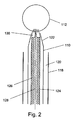
図2は、本発明の実施形態である外科用スネアの遠心端の部分的断面図である。本例において、スネアは、スコーピング装置(例えば、大腸内視鏡または内視鏡)の器具チャネル118を通過する寸法にされたカテーテル110を備える。図2に示されるように、器具チャネル118の内壁とカテーテル110の外壁の間にエアギャップ120(その大きさは図面では誇張されている)があるのが好ましい。このエアギャップは、治療中に吸引が器具チャネルを通って付与されることを可能にする。
FIG. 2 is a partial cross-sectional view of a distal end of a surgical snare according to an embodiment of the present invention. In this example, the snare comprises a
カテーテル110は遠心端に向かって直径が狭くなる先端セクション122を有する。先端セクション122は従って円錐体に似ているかもしれない。この配置はスネアを導入するための狭いアパーチャを提供し、それは、外科医によるコントロールを容易にさせる。
本例において、カテーテル110は、フレキシブルアクチュエータシャフト124のアウタスリーブ126に対して別個の存在として示されていて、それによってフレキシブルアクチュエータシャフト124はカテーテル110に対して摺動可能である。しかし、代替例においては、個別のカテーテル110は提供されず、アウタスリーブ126それ自体がカテーテルを形成する。従って、カテーテル110およびカテーテル110の任意の特徴の本明細書での言及は、個別のカテーテル110が存在していないアウタスリーブ126に等しく当てはまってもよいということが理解されよう。
In this example, the
カテーテル110(及び/またはアウタスリーブ126)はフレキシブルアクチュエータシャフト124を運ぶ柔軟な中空チューブである。カテーテルの材料は大腸内視鏡に押し通すことを容易にするのに十分な堅さを示すものが選ばれる。カテーテルは、ナイロン、PTFE(ポリテトラフルオロエチレン)、FEP(フッ化エチレンプロピレン)、編組FEP、PFA(p−フルオロフェニルアラニン)、ETFE(エチレンテトラフルオロエチレン共重合体)、PEEK(ポリエーテルエーテルケトン)等から作られていてもよい。
Catheter 110 (and / or outer sleeve 126) is a flexible hollow tube that carries
フレキシブルアクチュエータシャフト124は、カテーテル110内に摺動可能に受け入れられるアウタスリーブ126と、アウタスリーブ126内に摺動可能に受け入れられる、インナプッシュロッド128、例えば、ステンレススチールのワイヤ等、とを備える。
The
フレキシブルアクチュエータシャフト124はその遠心端にてキャップ130で終了し、キャップは堅いユニットであり、例えば、ステンレススチールから作られている。本実施形態では、ワイヤ112のループがカテーテル110から外へ延びるのを可能にする方法で、キャップ130はカテーテル110の先端セクション122に対して嵌まるように形作られている。例えば、端部キャップは、先端セクション122の内面と協同する複数の側面を備えていてもよい。
The
図2は、ワイヤ112のループを受け入れるためのT字形の内部通路と内部プッシュロッド128と共に、端部キャップを断面図において示している。
FIG. 2 shows the end cap in cross-section with a T-shaped internal passage for receiving the loop of
図3は、図2に示される位置から垂直軸のまわりに90°回転した時の端部キャップ130の側面図を示している。ここでは、端部キャップ130が2ピースで形成されていることが認識でき、それらは、ワイヤ112のループおよびインナプッシュロッド128が端部キャップ内に取り付けられた後に、例えば、溶接等によって、ともにしっかりと固定される。キャップ130は、従って、アウタスリーブ126に装着されるベース132を備える。本実施形態では、ベース132は先細り形状を有するが、カテーテル110内で摺動するのに適切などんな形状も使用されてよい。ベース132はそこにT字形のチャネル134を形成している。T字形のチャネル134のトップ(クロスバー)は、例えば、チャネルを形成するためにベース132の上面及び複数の側面で開口している。T字形のチャネル134の底はインナプッシュロッド128に出口を提供するために開口している。T字形のチャネル134内のループをしっかりと固定するために、端部キャップ130は、チャネルを閉鎖するためにベース132の上面に固定される(例えば、溶接される)、トップのピース136を含んでいる。例えば、部品の構造的一体化を向上させるために、トップのピース136はベース132の上面内のチャネル内へ嵌合するリッジ138を含んでいてもよい。トップのピース136の上面は、スネアが完全に退避させられる時に、ワイヤ112のループを受け取るためにトップのピース136の上面に形成された溝140を有していてもよい。
FIG. 3 shows a side view of the
ワイヤ112のループは、端部キャップから延ばされた時に丸い形を帯びるように十分な剛性及び弾性を有する材料から形成されるのが好ましい。本発明者らは、形状記憶特性を示す合金、例えば、ニッケルチタン(ニチノール)、が特によく適しているということが分かった。
The loop of
更に、本発明では、ワイヤ112のループは一定の円周長さを有する。即ち、一つの長さのワイヤ(例えばニチノール)の2つの端が、ループを形成するために(例えば溶接によって)ともに接合されている。ループの直径は、例えば20mmまでの任意の適切な寸法であってもよいが、好ましくは10mm未満、更に好ましくは8mm未満であってもよい。材料が形状記憶特性を有する場合、ループは所定の形状を安定して占めるように訓練されてもよい。このループ構成を使用するという利点は、形が一様に、つまり、キンクやニブ等の不連続がなく丸いということである。これによってループは、端部キャップ130に対して完全に閉じられることができ、不完全に切る危険を減らすまたはなくす。
Furthermore, in the present invention, the loop of
一旦このように形成されると、ワイヤ112のループはインナプッシュロッド128に取り付けられ、例えば、溶接され、さもなければしっかりと固定され、インナプッシュロッド128は十分な剛性を示すステンレススチールまたは他の材料であってもよい。インナプッシュロッド128は、T字路でワイヤ112のループと交わってもよく、これは、スネアが完全に配備された(延ばされた)時に、T字形のチャネル内に嵌まってもよい。アウタスリーブ126に対してインナプッシュロッド128を滑らせると、ワイヤのループは端部キャップ130内にまたはその端部キャップから外へ引っ張られる。アウタスリーブ126及びインナプッシュロッド128は、このように2重の作用配備シャフトとして働き、これらはともに、カテーテル110に対してワイヤ112のループを位置付けて、ワイヤ112のループを配備させる(延ばし退避させる)。
Once formed in this manner, the loop of
使用においては、ワイヤ112のループは生物組織を集め、スネアが退避されるにつれ端部キャップの方へ生物組織を引き戻す。トップのピース136(溝140の有無に関わらず)の上面は、従って、機械的な(圧力)切断/切除を行うために、ワイヤのループが組織を押す反作用表面として働く。図2において上面は水平であるように示されているが、実際上、上面は、例えば、ループが閉じられる時にループの形状と一致するように凸状であってもよい。
In use, the loop of
切断機能を支援するために、ワイヤ112のループには、例えば、ループの内方向に面する部分上に粗面が設けられてもよい。
In order to assist the cutting function, the loop of the
インナプッシュロッド128は、カテーテルの近位端にある従来のスライダによって操作可能であってもよい。スライダは、遠心端で必要かもしれない微動作を支援するために例えば、3:1のギア比を有するギアメカニズムを含んでいてもよい。
The
図4は、外科用スネアの別の実施形態を示す。図2に示されるスネアと共通の特徴には同一参照番号を付し、説明を省略する。本実施形態では、外科用スネアは、フレキシブルアクチュエータシャフト124に連結されることができる分離可能なスネアヘッド142備える。分離可能なスネアヘッド142は、上述されたワイヤ112のループ及び端部キャップ130を含む。しかし、端部キャップ130のベース132及びフレキシブルアクチュエータシャフト124の遠心端は、端部キャップ130をフレキシブルアクチュエータシャフト124へしっかりと固定するために係合可能な協同アタッチメント要素144、146を有する。協同アタッチメント要素144、146は、インターロック特徴、例えばバヨネットフィットを備えていてもよく、もしくは、ねじ、スプリングクリップ、タイ・ラップ留め具または軸方向に部品をしっかりと固定する他の手段を含んでいてもよい。
FIG. 4 illustrates another embodiment of a surgical snare. Features common to the snare shown in FIG. 2 are given the same reference numerals, and descriptions thereof are omitted. In this embodiment, the surgical snare comprises a separable snare head 142 that can be coupled to the
本実施形態では、インナプッシュロッド128の機能は、遠位連結棒148及び近位連結棒150によって提供される。遠位連結棒148はワイヤ112のループに取り付けられている(例えば、溶接されている)。また、近位連結棒150はカテーテル110の近位端でスライダ(不図示)からアウタスリーブ126を通って移動する。端部キャップ130がフレキシブルアクチュエータシャフト124にしっかりと固定されると、遠位連結棒148及び近位連結棒150は連結部152によって互いに係合する。係合されると、遠位連結棒148及び近位連結棒150は、インナプッシュロッド128の機能を行う単一の堅固な実体として働く。
In this embodiment, the function of the
図5は、外科用スネアの別の実施形態を示す。図2に示されるスネアと共通の特徴には同一参照番号を付し、説明を省略する。本実施形態では、シャープエッジまたはブレード154は、端部キャップ130(即ち上述された反作用表面の一部として)の上面に取り付けられるか、この上面と一体的に形成されている。ブレード154はきれいな切断を更に支援する。
FIG. 5 shows another embodiment of a surgical snare. Features common to the snare shown in FIG. 2 are given the same reference numerals, and descriptions thereof are omitted. In this embodiment, the sharp edge or
治療サイト(即ちワイヤ112のループ内に集められない組織)でブレード154が図らずも周囲組織を損傷してしまうのを防止するために、ブレード154及び/または端部キャップ130はそれらがカテーテル110内に完全に存在することを確実にするように構成されてもよい。言いかえれば、ブレード154の遠位エッジは、カテーテル110の先端セクション122の遠心端へ近接して位置付けられている。ワイヤ112のループがカテーテル110を越えて通り出られるように、端部キャップ130はトップのピース136の側壁にギャップまたはチャネルを含んでいてもよい。
In order to prevent the
図6は外科用スネアの別の実施形態を示す。図2に示されるスネアと共通の特徴には同一参照番号を付し、説明を省略する。本実施形態では、スネアの手術用部品はループされた長さのワイヤ156によって形成される。前の実施形態と異なり、ループを形成する長さのワイヤ156の端と端は接合されない。その代わりに、一端158はカテーテル110の内面に、例えば、カテーテルの先端セクション122に取り付けられている。取り付け箇所は、ループが十分に退避されることを可能にするために、先端セクションの遠位端から後退している。
FIG. 6 shows another embodiment of a surgical snare. Features common to the snare shown in FIG. 2 are given the same reference numerals, and descriptions thereof are omitted. In this embodiment, the snare surgical component is formed by a looped length of
ワイヤ156の他端160はインナプッシュロッド128の遠位端に取り付けられる、例えば、溶接される。上述したように、ワイヤ156は、それがカテーテル110から延出された時にループ状の構成を取る傾向を有するように形状記憶特性を示す合金(例えばニチノール)から形成されていてもよい。
The
上述された実施形態におけるように、端部キャップ162はフレキシブルアクチュエータシャフト124の遠位端を終結させる。この実施形態では、端部キャップ162は、スネアの配備中ワイヤ156(及びインナープッシュロッド128)が通って走る軸方向通路を備えていてもよい。端部キャップ162は、従って、(例えばステンレススチールの)単一ピースとして形成されてもよい。
As in the embodiment described above, the
ワイヤがカテーテル110内部の取り付け箇所からそれを過ぎて走ることを可能にするために、端部キャップ162は、その外表面内に形成されたチャネル164またはギャップを有してもよい。
使用中、ループで取り囲まれた生物組織を端部キャップ162の上面に対して引くために、ワイヤはチーズワイヤのように作用してもよい。
In use, the wire may act like a cheese wire to pull biological tissue surrounded by the loop against the top surface of the
図7は、外科用スネアの別の実施形態を示す。図6に示されるスネアと共通の特徴には同一参照番号を付し、説明を省略する。本実施形態では、スネアの手術部は2重ワイヤのループ166により形成されている。本実施形態では、端部キャップは、2重ワイヤのループ166の1部分を受け取るためのU字形通路168を含んでいる。これは、反作用表面を支持するための手段としてループを閉じるために使用される力を利用する効果を有し、これにより切断プロセスに対するより大きなコントロールが与えられる。更に、1例において、ループが閉じられている間に端部キャップの外からループ内の収集組織と接触させることができる(スプリング等によって端部キャップ内へ後方にバイアスをかけられた)移動可能なチップ部分170を端部キャップは含んでいてもよい。移動可能なチップ部分170はその上に取り付けられた鋭利な遠位エッジまたはブレードを有していてもよい。
FIG. 7 shows another embodiment of a surgical snare. Features common to the snare shown in FIG. 6 are given the same reference numerals, and descriptions thereof are omitted. In this embodiment, the snare surgical section is formed by a double-
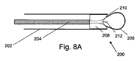
図8Aは、別の実施形態によるスネア装置200の遠位端を通る概略断面図を示す。スネア装置200は、(例えばフォームナイロンで作られた)アウタスリーブ202と、アウタスリーブ202内に取り付けられアウタスリーブ202に対して摺動可能な(例えば、ステンレススチールから作られた)インナプッシュロッド204とを備えたフレキシブルアクチュエータシャフトを備える。ワイヤ206のニブレスループはインナプッシュロッドの遠位端に接続される。ワイヤのループは複数の編んだニチノール撚り線または一つのニチノール撚り線で作られていてもよい。本例において、ループの両端はプッシュロッド204に接続される。しかし、1つの端が端部キャップ208に(例えば内部通路内に)に固定され、他端がプッシュロッド204に固定されることも有り得る。ワイヤ206のループは、アウタスリーブ202の遠心端に取り付けられた端部キャップ208を通じてプッシュロッド204の作用により摺動可能である。端部キャップはステンレススチールから作られていてもよい。端部キャップ208はワイヤのニブレスループを受け取るために内部通路(不図示)を有している。本実施形態では、端部キャップ208は窪みのある遠位表面210を有し、そこから薄いブレード212が突出する。端部キャップ208へ完全に退避させられた時にワイヤ206のニブレスループが当接する反作用表面を提供する内部通路の入口にブレード212は跨っている。ブレードはループ内で捕らえられた組織の切断を支援する。窪みのある遠位表面は、ブレードの先端がアウタスリーブ202の端を実質的に越えて突出しないことを確保する。
FIG. 8A shows a schematic cross-sectional view through the distal end of a
図8Bは、別の実施形態によるスネア装置214の遠位端を通る概略断面図を示す。図8Aに示されるスネアと共通の特徴には同一参照番号を付し、説明を省略する。本実施形態では、端部キャップ208は1組の内部通路を、ループ206の各端に1つずつ備える。端部キャップ208は内部通路への入口間の切断領域218で鋭利にされた凹状遠位面216を有する。切断領域218は、端部キャップ208内へ完全に退避させられた時にワイヤ206のニブレスループが当接する反作用表面を形成する。凹状の遠位面216は、切断領域がアウタスリーブ202の端を越えて突出しないことを確保する。
FIG. 8B shows a schematic cross-sectional view through the distal end of the
図8Cは、別の実施形態によるスネア装置220の遠位端を通る概略断面図を示す。図8Aに示されるスネアと共通の特徴には同一参照番号を付し、説明を省略する。本実施形態では、端部キャップ208はまた、1組の内部通路(不図示)を、ループ206の各端に1つずつ備える。端部キャップ208は後退した口222を有し、前記1組の通路の遠位端は後退した口のベースに開口している。後退した口222のベースは、内部通路への入口間の切断領域224で鋭利にされている。切断領域224は、端部キャップ208内へ完全に退避させられた時にワイヤ206のニブレスループが当接する反作用表面を形成する。後退した口222は、切断領域がアウタスリーブ202の端を越えて突出しないことを確保する。
FIG. 8C shows a schematic cross-sectional view through the distal end of the
上に説明された実施形態の全てにおいて、ワイヤのループはカテーテルの先端セクションから遠位に延びる。他の実施形態では、スネアキャップ内の通路は先端セクションの側面を通って開口していてもよく、その結果、ワイヤのループは装置の片方に向けられる。 In all of the embodiments described above, the wire loop extends distally from the tip section of the catheter. In other embodiments, the passage in the snare cap may open through the side of the tip section so that the loop of wire is directed to one side of the device.
Claims (15)
前記アウタスリーブの遠位端に取り付けられた端部キャップと、
前記インナプッシュロッドの遠心端へ接続されたワイヤのニブレスループと、を備え、
前記端部キャップはワイヤの前記ニブレスループを受け取るための通路を含み、それによって前記インナプッシュロッドは、ワイヤの前記ニブレスループを前記端部キャップ内へ退避させるように動作可能であり、
前記端部キャップは、その遠心端に、ワイヤの前記ニブレスループが前記端部キャップ内へ完全に退避させられた時に当接する反作用表面を含んでおり、
前記反作用表面は、前記端部キャップへ完全に退避させられた時のワイヤの前記ニブレスループを受け取るための溝を含んでいる、外科用スネア。 An outer sleeve, and a flexible actuator shaft comprising an inner push rod mounted in the outer sleeve and slidable with respect to the outer sleep;
An end cap attached to the distal end of the outer sleeve;
A wire nibless loop connected to the distal end of the inner push rod,
The end cap includes a passage for receiving the nibless loop of wire, whereby the inner push rod is operable to retract the nibless loop of wire into the end cap;
The end cap includes at its distal end a reaction surface that abuts when the nibble loop of wire is fully retracted into the end cap;
The surgical snare wherein the reaction surface includes a groove for receiving the nibless loop of wire when fully retracted to the end cap.
Applications Claiming Priority (3)
| Application Number | Priority Date | Filing Date | Title |
|---|---|---|---|
| GBGB1418368.5A GB201418368D0 (en) | 2014-10-16 | 2014-10-16 | Surgical snare |
| GB1418368.5 | 2014-10-16 | ||
| PCT/EP2015/074004 WO2016059210A1 (en) | 2014-10-16 | 2015-10-16 | Surgical snare |
Publications (3)
| Publication Number | Publication Date |
|---|---|
| JP2017531512A JP2017531512A (en) | 2017-10-26 |
| JP2017531512A5 JP2017531512A5 (en) | 2018-11-01 |
| JP6607933B2 true JP6607933B2 (en) | 2019-11-20 |
Family
ID=52013082
Family Applications (1)
| Application Number | Title | Priority Date | Filing Date |
|---|---|---|---|
| JP2017520455A Active JP6607933B2 (en) | 2014-10-16 | 2015-10-16 | Surgical snare |
Country Status (13)
| Country | Link |
|---|---|
| US (1) | US10835270B2 (en) |
| EP (1) | EP3206601B1 (en) |
| JP (1) | JP6607933B2 (en) |
| KR (1) | KR20170068495A (en) |
| CN (1) | CN107072687B (en) |
| AU (1) | AU2015332595B2 (en) |
| BR (1) | BR112017007354B1 (en) |
| CA (1) | CA2964668C (en) |
| ES (1) | ES2926060T3 (en) |
| GB (2) | GB201418368D0 (en) |
| PT (1) | PT3206601T (en) |
| SG (1) | SG11201703052UA (en) |
| WO (1) | WO2016059210A1 (en) |
Families Citing this family (39)
| Publication number | Priority date | Publication date | Assignee | Title |
|---|---|---|---|---|
| US6814739B2 (en) | 2001-05-18 | 2004-11-09 | U.S. Endoscopy Group, Inc. | Retrieval device |
| US8591521B2 (en) | 2007-06-08 | 2013-11-26 | United States Endoscopy Group, Inc. | Retrieval device |
| US8070694B2 (en) | 2008-07-14 | 2011-12-06 | Medtronic Vascular, Inc. | Fiber based medical devices and aspiration catheters |
| US9572591B2 (en) | 2013-09-03 | 2017-02-21 | United States Endoscopy Group, Inc. | Endoscopic snare device |
| US9265512B2 (en) | 2013-12-23 | 2016-02-23 | Silk Road Medical, Inc. | Transcarotid neurovascular catheter |
| RU2019132037A (en) | 2014-09-17 | 2019-12-02 | Янтек, Инк. | DEVICES AND METHODS FOR REMOVING CRYSTAL FABRIC |
| US9629747B2 (en) | 2014-09-17 | 2017-04-25 | Iantech, Inc. | Devices and methods for cutting lenticular tissue |
| US10426497B2 (en) | 2015-07-24 | 2019-10-01 | Route 92 Medical, Inc. | Anchoring delivery system and methods |
| US11065019B1 (en) | 2015-02-04 | 2021-07-20 | Route 92 Medical, Inc. | Aspiration catheter systems and methods of use |
| JP6732769B2 (en) | 2015-02-04 | 2020-07-29 | ルート92メディカル・インコーポレイテッドRoute 92 Medical, Inc. | Rapid suction thrombectomy system and method |
| US10716915B2 (en) * | 2015-11-23 | 2020-07-21 | Mivi Neuroscience, Inc. | Catheter systems for applying effective suction in remote vessels and thrombectomy procedures facilitated by catheter systems |
| US10624785B2 (en) | 2016-01-30 | 2020-04-21 | Carl Zeiss Meditec Cataract Technology Inc. | Devices and methods for ocular surgery |
| WO2017203582A1 (en) * | 2016-05-23 | 2017-11-30 | オリンパス株式会社 | Endoscope-use device, and endoscopic system |
| US11413188B2 (en) | 2016-10-26 | 2022-08-16 | Carl Zeiss Meditec Cataract Technology Inc. | Devices and methods for cutting a lens in an eye |
| US10667838B2 (en) * | 2017-01-09 | 2020-06-02 | United States Endoscopy Group, Inc. | Endoscopic snare device |
| EP4134120A1 (en) | 2017-01-10 | 2023-02-15 | Route 92 Medical, Inc. | Aspiration catheter systems |
| CN106725738A (en) * | 2017-01-17 | 2017-05-31 | 李达周 | Soft endoscopic tissue reducing mechanism |
| CN106983539B (en) * | 2017-05-08 | 2020-05-19 | 南微医学科技股份有限公司 | Medical rotatable snare |
| CA3062650C (en) * | 2017-05-12 | 2021-11-16 | Ellenial Surgical, LLC | Fecalith removal system |
| US10478535B2 (en) | 2017-05-24 | 2019-11-19 | Mivi Neuroscience, Inc. | Suction catheter systems for applying effective aspiration in remote vessels, especially cerebral arteries |
| US11234723B2 (en) | 2017-12-20 | 2022-02-01 | Mivi Neuroscience, Inc. | Suction catheter systems for applying effective aspiration in remote vessels, especially cerebral arteries |
| KR102058037B1 (en) * | 2017-10-11 | 2020-01-22 | (주)비엠에이 | Medical snare |
| KR102035102B1 (en) * | 2017-11-09 | 2019-10-22 | 석재일 | Endoscopic tool |
| AU2018378808A1 (en) * | 2017-12-08 | 2020-05-21 | Auris Health, Inc. | Directed fluidics |
| BR112020011860A2 (en) | 2017-12-14 | 2020-11-24 | Carl Zeiss Meditec Cataract Technology Inc. | devices and methods for eye surgery |
| CN112423824B (en) | 2018-05-17 | 2023-02-21 | 92号医疗公司 | Aspiration catheter system and method of use |
| US10881280B2 (en) | 2018-08-24 | 2021-01-05 | Auris Health, Inc. | Manually and robotically controllable medical instruments |
| US10765487B2 (en) | 2018-09-28 | 2020-09-08 | Auris Health, Inc. | Systems and methods for docking medical instruments |
| US11723637B2 (en) * | 2018-10-19 | 2023-08-15 | New Wave Endo-Surgical Corp. | Method and apparatus for intra-abdominal assembly, disassembly and retrieval of laparoscopic instruments |
| WO2020140072A1 (en) | 2018-12-28 | 2020-07-02 | Auris Health, Inc. | Percutaneous sheath for robotic medical systems and methods |
| US11007079B1 (en) | 2019-12-02 | 2021-05-18 | Richard Mackool | Ophthalmic surgical instruments and snares thereof |
| CA3143470A1 (en) * | 2019-06-24 | 2020-12-30 | Richard Mackool | Ophthalmic surgical instruments and snares thereof |
| EP4013285A4 (en) | 2019-08-15 | 2023-11-22 | Auris Health, Inc. | Medical device having multiple bending sections |
| CN114929148A (en) | 2019-12-31 | 2022-08-19 | 奥瑞斯健康公司 | Alignment interface for percutaneous access |
| US11298195B2 (en) | 2019-12-31 | 2022-04-12 | Auris Health, Inc. | Anatomical feature identification and targeting |
| WO2021137109A1 (en) | 2019-12-31 | 2021-07-08 | Auris Health, Inc. | Alignment techniques for percutaneous access |
| US11617865B2 (en) | 2020-01-24 | 2023-04-04 | Mivi Neuroscience, Inc. | Suction catheter systems with designs allowing rapid clearing of clots |
| DE202020104255U1 (en) | 2020-07-23 | 2021-10-26 | Hms Medical Gmbh | Device for removing raised cell tissue, in particular tumors |
| US20230346405A1 (en) * | 2022-04-28 | 2023-11-02 | United States Government As Represented By The Department Of Veterans Affairs | Clot Disruptor And Systems And Methods Of Using Same |
Family Cites Families (32)
| Publication number | Priority date | Publication date | Assignee | Title |
|---|---|---|---|---|
| JPS482474Y1 (en) | 1969-12-23 | 1973-01-22 | ||
| US4538611A (en) | 1983-06-13 | 1985-09-03 | Kelman Charles D | Surgical instrument and method of cutting a lens of an eye |
| US4718419A (en) | 1985-08-05 | 1988-01-12 | Olympus Optical Co., Ltd. | Snare assembly for endoscope |
| US5318564A (en) | 1992-05-01 | 1994-06-07 | Hemostatic Surgery Corporation | Bipolar surgical snare and methods of use |
| JPH1014922A (en) | 1996-07-03 | 1998-01-20 | Osamu Yoshida | Organ slicer and organ slicing device |
| JP3806516B2 (en) * | 1998-07-02 | 2006-08-09 | オリンパス株式会社 | Endoscope system |
| EP1112229A4 (en) * | 1998-05-29 | 2004-06-16 | Proton Energy Systems | Fluids management system for water electrolysis |
| US6007546A (en) * | 1998-10-26 | 1999-12-28 | Boston Scientific Ltd. | Injection snare |
| US20030135222A1 (en) * | 2000-02-17 | 2003-07-17 | Kanag Baska | Surgical snare |
| AU2001233500B2 (en) | 2000-02-17 | 2005-02-17 | Kanag Baska | Surgical snare |
| US6602262B2 (en) * | 2000-06-02 | 2003-08-05 | Scimed Life Systems, Inc. | Medical device having linear to rotation control |
| US20040220604A1 (en) * | 2003-04-30 | 2004-11-04 | Fogarty Thomas J. | Tissue separation apparatus and method |
| JP2005110860A (en) * | 2003-10-06 | 2005-04-28 | Olympus Corp | Ligator device for medical use |
| JP4638683B2 (en) | 2004-03-25 | 2011-02-23 | テルモ株式会社 | Intravascular foreign body removal aspiration catheter |
| US7658738B2 (en) | 2004-05-14 | 2010-02-09 | Ethicon Endo-Surgery, Inc. | Medical devices for use with endoscope |
| CN2745521Y (en) | 2004-12-06 | 2005-12-14 | 何菊 | Atheroscleorsis plaque cutting instrument |
| US7297136B2 (en) | 2004-12-06 | 2007-11-20 | Wyrick Ronald E | Medicine injection devices and methods |
| US20060173468A1 (en) | 2005-01-28 | 2006-08-03 | Marc Simmon | Obturator introducer with snare |
| JP4823533B2 (en) * | 2005-02-04 | 2011-11-24 | オリンパス株式会社 | Medical suture ligation tool and medical suture ligation apparatus |
| US8932208B2 (en) * | 2005-05-26 | 2015-01-13 | Maquet Cardiovascular Llc | Apparatus and methods for performing minimally-invasive surgical procedures |
| EP2079373B1 (en) * | 2006-09-21 | 2018-12-19 | Mayo Foundation For Medical Education And Research | Devices for ligating anatomical structures |
| US8298243B2 (en) * | 2007-07-30 | 2012-10-30 | Tyco Healthcare Group Lp | Combination wire electrode and tube electrode polypectomy device |
| EP2052688B1 (en) * | 2007-10-25 | 2012-06-06 | pfm medical ag | Snare mechanism for surgical retrieval |
| US20090182324A1 (en) * | 2008-01-16 | 2009-07-16 | Mel Kurtulus | Laproscopic electronic surgical instruments |
| US8328803B2 (en) * | 2008-01-31 | 2012-12-11 | Covidien Lp | Polyp removal device and method of use |
| US8961543B2 (en) * | 2008-10-20 | 2015-02-24 | Mayo Foundation For Medical Education And Research | Tissue ligation devices and methods |
| CN201453327U (en) * | 2009-06-25 | 2010-05-12 | 安瑞医疗器械(杭州)有限公司 | Snare |
| DK2493392T3 (en) * | 2009-10-30 | 2016-08-01 | Cook Medical Technologies Llc | Apparatus for maintaining a force in a tissue using a loop element |
| CN202010184U (en) * | 2011-02-17 | 2011-10-19 | 上海菲捷实业有限公司 | Disposable surgical high-frequency snare |
| US20140364866A1 (en) * | 2012-01-06 | 2014-12-11 | University Of Louisville Research Foundation, Inc. | Endoscopic snare device |
| EP2948075B1 (en) * | 2013-01-23 | 2020-07-15 | Boston Scientific Scimed, Inc. | Surgical snare device |
| US10945756B2 (en) * | 2013-03-01 | 2021-03-16 | Catch Medical, Llc | Device of inserting and controlling a snare |
-
2014
- 2014-10-16 GB GBGB1418368.5A patent/GB201418368D0/en not_active Ceased
-
2015
- 2015-10-16 GB GB1518324.7A patent/GB2532596B/en not_active Expired - Fee Related
- 2015-10-16 WO PCT/EP2015/074004 patent/WO2016059210A1/en active Application Filing
- 2015-10-16 KR KR1020177011687A patent/KR20170068495A/en active IP Right Grant
- 2015-10-16 CA CA2964668A patent/CA2964668C/en active Active
- 2015-10-16 SG SG11201703052UA patent/SG11201703052UA/en unknown
- 2015-10-16 EP EP15784000.0A patent/EP3206601B1/en active Active
- 2015-10-16 ES ES15784000T patent/ES2926060T3/en active Active
- 2015-10-16 PT PT157840000T patent/PT3206601T/en unknown
- 2015-10-16 AU AU2015332595A patent/AU2015332595B2/en active Active
- 2015-10-16 CN CN201580056221.3A patent/CN107072687B/en active Active
- 2015-10-16 BR BR112017007354-4A patent/BR112017007354B1/en active IP Right Grant
- 2015-10-16 US US15/518,725 patent/US10835270B2/en active Active
- 2015-10-16 JP JP2017520455A patent/JP6607933B2/en active Active
Also Published As
| Publication number | Publication date |
|---|---|
| US20170231647A1 (en) | 2017-08-17 |
| CN107072687A (en) | 2017-08-18 |
| WO2016059210A1 (en) | 2016-04-21 |
| AU2015332595B2 (en) | 2019-08-01 |
| SG11201703052UA (en) | 2017-05-30 |
| CN107072687B (en) | 2023-12-05 |
| EP3206601A1 (en) | 2017-08-23 |
| CA2964668A1 (en) | 2016-04-21 |
| GB2532596A (en) | 2016-05-25 |
| CA2964668C (en) | 2023-01-17 |
| GB2532596B (en) | 2017-05-10 |
| US10835270B2 (en) | 2020-11-17 |
| BR112017007354B1 (en) | 2022-11-16 |
| JP2017531512A (en) | 2017-10-26 |
| PT3206601T (en) | 2022-08-31 |
| AU2015332595A1 (en) | 2017-05-18 |
| BR112017007354A2 (en) | 2017-12-19 |
| GB201518324D0 (en) | 2015-12-02 |
| GB201418368D0 (en) | 2014-12-03 |
| EP3206601B1 (en) | 2022-07-27 |
| KR20170068495A (en) | 2017-06-19 |
| ES2926060T3 (en) | 2022-10-21 |
Similar Documents
| Publication | Publication Date | Title |
|---|---|---|
| JP6607933B2 (en) | Surgical snare | |
| JP6211541B2 (en) | Cutting tool with circulation wire | |
| AU2015201540B2 (en) | Devices, systems, and methods for obtaining a tissue sample using a biopsy tool | |
| EP2025298B1 (en) | Endoscopic high-frequency knife | |
| EP1948027B1 (en) | Tissue cutting devices having hemostasis capability | |
| JPWO2007102586A1 (en) | Endoscopic treatment tool | |
| US20140378988A1 (en) | Supported retrieval device and related methods of use | |
| EP2797518B1 (en) | Adjustable resection device | |
| JPWO2015133434A1 (en) | Endoscopic treatment tool and incision system | |
| US9901363B2 (en) | Resection device and related methods of use | |
| US9549661B2 (en) | Medical device actuation systems and related methods of use | |
| JP2007301285A (en) | High-frequency treatment instrument | |
| US10765444B2 (en) | Medical instrument for ablation of tissue | |
| JP2019000215A (en) | Treatment instrument for endoscope | |
| US20210298581A1 (en) | Adjustable-shape snare for endoscopic procedures | |
| JP6874001B2 (en) | Medical equipment and usage |
Legal Events
| Date | Code | Title | Description |
|---|---|---|---|
| A521 | Request for written amendment filed |
Free format text: JAPANESE INTERMEDIATE CODE: A523 Effective date: 20180920 |
|
| A621 | Written request for application examination |
Free format text: JAPANESE INTERMEDIATE CODE: A621 Effective date: 20180920 |
|
| A131 | Notification of reasons for refusal |
Free format text: JAPANESE INTERMEDIATE CODE: A131 Effective date: 20190618 |
|
| A977 | Report on retrieval |
Free format text: JAPANESE INTERMEDIATE CODE: A971007 Effective date: 20190621 |
|
| A521 | Request for written amendment filed |
Free format text: JAPANESE INTERMEDIATE CODE: A523 Effective date: 20190906 |
|
| TRDD | Decision of grant or rejection written | ||
| A01 | Written decision to grant a patent or to grant a registration (utility model) |
Free format text: JAPANESE INTERMEDIATE CODE: A01 Effective date: 20190924 |
|
| A61 | First payment of annual fees (during grant procedure) |
Free format text: JAPANESE INTERMEDIATE CODE: A61 Effective date: 20191021 |
|
| R150 | Certificate of patent or registration of utility model |
Ref document number: 6607933 Country of ref document: JP Free format text: JAPANESE INTERMEDIATE CODE: R150 |
|
| R250 | Receipt of annual fees |
Free format text: JAPANESE INTERMEDIATE CODE: R250 |
|
| R250 | Receipt of annual fees |
Free format text: JAPANESE INTERMEDIATE CODE: R250 |