JP6603674B2 - Winding device for wrappable materials such as strands - Google Patents
Winding device for wrappable materials such as strands Download PDFInfo
- Publication number
- JP6603674B2 JP6603674B2 JP2016568878A JP2016568878A JP6603674B2 JP 6603674 B2 JP6603674 B2 JP 6603674B2 JP 2016568878 A JP2016568878 A JP 2016568878A JP 2016568878 A JP2016568878 A JP 2016568878A JP 6603674 B2 JP6603674 B2 JP 6603674B2
- Authority
- JP
- Japan
- Prior art keywords
- traverse
- spool
- winding
- lance
- winding device
- Prior art date
- Legal status (The legal status is an assumption and is not a legal conclusion. Google has not performed a legal analysis and makes no representation as to the accuracy of the status listed.)
- Active
Links
Images


Classifications
-
- B—PERFORMING OPERATIONS; TRANSPORTING
- B65—CONVEYING; PACKING; STORING; HANDLING THIN OR FILAMENTARY MATERIAL
- B65H—HANDLING THIN OR FILAMENTARY MATERIAL, e.g. SHEETS, WEBS, CABLES
- B65H54/00—Winding, coiling, or depositing filamentary material
- B65H54/02—Winding and traversing material on to reels, bobbins, tubes, or like package cores or formers
- B65H54/28—Traversing devices; Package-shaping arrangements
- B65H54/2848—Arrangements for aligned winding
- B65H54/2854—Detection or control of aligned winding or reversal
- B65H54/2869—Control of the rotating speed of the reel or the traversing speed for aligned winding
- B65H54/2872—Control of the rotating speed of the reel or the traversing speed for aligned winding by detection of the incidence angle
-
- B—PERFORMING OPERATIONS; TRANSPORTING
- B65—CONVEYING; PACKING; STORING; HANDLING THIN OR FILAMENTARY MATERIAL
- B65H—HANDLING THIN OR FILAMENTARY MATERIAL, e.g. SHEETS, WEBS, CABLES
- B65H54/00—Winding, coiling, or depositing filamentary material
- B65H54/02—Winding and traversing material on to reels, bobbins, tubes, or like package cores or formers
- B65H54/28—Traversing devices; Package-shaping arrangements
- B65H54/2806—Traversing devices driven by cam
- B65H54/2809—Traversing devices driven by cam rotating grooved cam
- B65H54/2812—Traversing devices driven by cam rotating grooved cam with a traversing guide running in the groove
-
- B—PERFORMING OPERATIONS; TRANSPORTING
- B65—CONVEYING; PACKING; STORING; HANDLING THIN OR FILAMENTARY MATERIAL
- B65H—HANDLING THIN OR FILAMENTARY MATERIAL, e.g. SHEETS, WEBS, CABLES
- B65H54/00—Winding, coiling, or depositing filamentary material
- B65H54/02—Winding and traversing material on to reels, bobbins, tubes, or like package cores or formers
- B65H54/28—Traversing devices; Package-shaping arrangements
- B65H54/2848—Arrangements for aligned winding
- B65H54/2851—Arrangements for aligned winding by pressing the material being wound against the drum, flange or already wound material, e.g. by fingers or rollers; guides moved by the already wound material
-
- B—PERFORMING OPERATIONS; TRANSPORTING
- B65—CONVEYING; PACKING; STORING; HANDLING THIN OR FILAMENTARY MATERIAL
- B65H—HANDLING THIN OR FILAMENTARY MATERIAL, e.g. SHEETS, WEBS, CABLES
- B65H2701/00—Handled material; Storage means
- B65H2701/30—Handled filamentary material
- B65H2701/36—Wires
Description
優先出願である独国特許発明第10 2014 007 552.4号明細書の全内容は、本明細書において参照することによって本出願に組み込まれる。
The entire content of the
本発明は、回転スプール上でストランドのような巻付可能材料を巻き取るための巻取装置に関する。 The present invention relates to a winding device for winding a rollable material such as a strand on a rotating spool.
ストランドのような巻付可能材料は、例えば、金属又は非金属の被覆又は非被覆線、シングルケーブルもしくは多心ケーブル、ストランド、繊維、例えば天然繊維もしくは合成繊維、特に、光ファイバーケーブル、フィラメント、コード又はロープのような特定の技術的適用のための繊維である。 A wrappable material such as a strand can be, for example, a metal or non-metal coated or uncoated wire, a single cable or a multi-core cable, a strand, a fiber, such as a natural or synthetic fiber, in particular a fiber optic cable, a filament, a cord or A fiber for specific technical applications such as ropes.
スプールは、好ましくはシリンダ状、円錐状もしくはさらに二重円錐状のスプール本体を有する好ましくは回転対称体として理解される。スプールは、スプール本体の端部に配置された、少なくとも1つの好ましくはディスク状のフランジをさらに備え、フランジの直径は、通常、スプール本体の最も大きい直径よりも顕著に大きい。 The spool is preferably understood as a rotationally symmetric body, preferably having a cylindrical, conical or even double-conical spool body. The spool further comprises at least one preferably disc-shaped flange disposed at the end of the spool body, the diameter of the flange being typically significantly larger than the largest diameter of the spool body.
問題のタイプの巻取装置は、トラバース機構をさらに備え、巻付可能材料は、トラバース機構によってスプール巻取部上の進行ポイントにガイドされる。それに関して、進行ポイントは、巻取プロセス中に巻付可能材料がスプール上のスプール巻取部に入るポイント、従って巻付可能材料がその移動方向から見るとすでに形成されたスプール巻取部と最初に接触するポイントとして理解される。従って進行ポイントの場所は、巻取装置の非移動部に対して且つ巻取プロセス中に周囲に対して変化する。 The take-up device of the type in question further comprises a traverse mechanism, and the wrappable material is guided by the traverse mechanism to an advance point on the spool winder. In that regard, the progression point is the point at which the wrappable material enters the spool take-up on the spool during the take-up process, so that the spool take-up material is first formed with respect to the spool take-up already formed when viewed from its direction of travel. To be understood as the point of contact. Thus, the location of the advance point changes relative to the non-moving part of the winding device and to the surroundings during the winding process.
トラバース機構は、スプールの回転軸の方向に実質的に移動可能である。 The traverse mechanism is substantially movable in the direction of the rotation axis of the spool.
スプールがその回転軸周りに回転すること及び巻付可能材料がトラバース機構を介して同時に供給されることによって、巻付可能材料の個々の巻線部がスプール上で形成される。トラバース機構がスプールの回転軸の方向にさらに移動することによって、巻線部は、最終的にスプール上で互いに並行に位置し、従って連続的な巻線部の層を形成する。 As the spool rotates about its axis of rotation and the wrappable material is fed simultaneously via the traverse mechanism, individual windings of the wrappable material are formed on the spool. As the traverse mechanism moves further in the direction of the axis of rotation of the spool, the windings eventually lie parallel to each other on the spool and thus form a continuous winding layer.
さまざまなタイプの巻線部の幾何学的形状、例えば螺旋状及び環状巻線部が、公知である。 Various types of winding geometry, such as spiral and annular windings, are known.
スプール巻取部のそれぞれの終端ポイントにおいて、例えば提供されるのであればスプールのそれぞれのフランジにおいてトラバース機構の移動方向を適切に変化させることによって、1つの層の形成が終了し、別の層がすでに形成された層の上に形成し始める。 By appropriately changing the direction of movement of the traverse mechanism at each end point of the spool winding, for example at each flange of the spool, if provided, the formation of one layer is terminated and another layer is Start forming on the already formed layer.
緊密に隣り合った巻線部の複数の層からなる均一なスプール巻取部を形成するために、スプール巻線部が一様でない直径を有することをもたらす、“中断”、すなわち間隙が巻線部の間に形成しないこと、また巻線部が直前に形成された巻線部上に“積み重ならないこと”及び巻線部を“飛び越えないこと”を保証しなければならない。これは、スプールの回転速度と、巻付可能材料の特性、例えば巻付可能材料の直径、表面構造、その表面の摩擦係数またはその剛性と、の下で、回転軸の方向におけるトラバース機構の変位速度の良好な制御を必要とする。 In order to form a uniform spool winding consisting of multiple layers of closely adjacent windings, the "interrupt", i.e. the gap, causes the spool windings to have a non-uniform diameter. It must be ensured that it does not form between the parts, and that the winding part “does not stack” on the immediately preceding winding part and “does not jump over” the winding part. This is the displacement of the traverse mechanism in the direction of the axis of rotation under the rotation speed of the spool and the characteristics of the wrappable material, eg the diameter of the wrappable material, the surface structure, the coefficient of friction of the surface or its rigidity. Requires good control of speed.
巻付可能材料の進行角度に応じて巻取プロセス中にトラバース機構の移動を調整することは、証明された利点を有する。進行角度は、スプールの回転軸に対して垂直な方向と巻付可能材料の進行軸との間の角度であり、そのために、進行軸は、それに沿って巻付可能材料がスプール巻取部上に入る軸を参照する。 Adjusting the movement of the traverse mechanism during the winding process according to the angle of advance of the wrappable material has a proven advantage. The advancing angle is the angle between the direction perpendicular to the axis of rotation of the spool and the advancing axis of the wrappable material, so that the advancing axis has a wrappable material on the spool take-up along it. Refers to the axis that enters.
例えば、進行角度が、スプールの回転軸に対して垂直な方向、すなわち巻取部がスプール上に形成する方向から見るとトラバース機構の移動方向に向かって開いており、且つその大きさが特定の値を超える場合、これは、トラバース機構が、移動方向から見ると極めて後方に位置していることを意味し、このとき、制御は、変位速度を若干増大させるべきである。他方で、進行角度が移動方向に対して反対に開いており、且つ特定の値だけその大きさを超える場合、制御は、結果として変位速度を若干減少させるべきである。 For example, the advancing angle is open toward the moving direction of the traverse mechanism when viewed from the direction perpendicular to the rotation axis of the spool, that is, the direction in which the take-up portion forms on the spool, and the size of the moving angle is a specific size. If the value is exceeded, this means that the traverse mechanism is located very rearward when viewed from the direction of travel, at which time the control should increase the displacement speed slightly. On the other hand, if the advance angle is open opposite to the direction of movement and exceeds its magnitude by a certain value, control should result in a slight decrease in displacement speed.
そのため、巻取装置は、巻付可能材料の進行角度を決定するための少なくとも1つのセンサを備えている。 For this purpose, the winding device comprises at least one sensor for determining the advance angle of the rollable material.
進行角度に応じたトラバース機構の変位のこのような調整は、例えば特許文献1及び2で使用されている。
Such adjustment of the displacement of the traverse mechanism according to the traveling angle is used in
本発明が基づいている課題は、回転スプール上でストランドのような巻付可能材料を巻き取るための説明されたタイプの巻取装置をさらに改良することである。 The problem on which the present invention is based is to further improve a winding device of the described type for winding a rollable material such as a strand on a rotating spool.
この課題は、請求項1に従う巻取装置によって解決される。本発明のさらに有利な実施形態は、従属請求項で記載されている。
This problem is solved by a winding device according to
本発明の巻取装置では、巻取プロセス中に離脱ポイントと進行ポイントとの間の距離が、少なくとも断続的に、巻付可能材料の直径の4倍未満であり、好ましくは2倍未満であり、さらに好ましくは最大でも巻付可能材料の直径と等しい。離脱ポイントが理解されるように、ここでの離脱ポイントは、巻付可能材料がトラバース機構から離れるポイントであり、すなわち巻付可能材料がその移動方向から見たときにトラバース機構と最後に接触しているポイントである。 In the winding device of the invention, during the winding process, the distance between the break-off point and the advance point is at least intermittently less than 4 times the diameter of the wrappable material, preferably less than 2 times. More preferably, it is at most equal to the diameter of the rollable material. As understood by the separation point, the separation point here is the point at which the wrappable material leaves the traverse mechanism, i.e. the last contact of the wrappable mechanism with the wrappable material when viewed from its direction of travel. It is a point.
優先的に、巻取プロセス中の離脱ポイントと進行ポイントとの間の距離は、さらに常に、巻付可能材料の直径の4倍未満であり、好ましくは2倍未満であり、さらに好ましくは最大でも巻付可能材料の直径と等しい。 Preferentially, the distance between the break-off point and the advance point during the winding process is always always less than 4 times the diameter of the rollable material, preferably less than 2 times, more preferably at most Equal to the diameter of the wrappable material.
巻付可能材料がガイドされない、従って空間内で“自由に”移動する、離脱ポイントと進行ポイントとの間のこの短い距離は、巻付可能材料の信頼性の高く且つ正確なガイドを可能にし、従って個々の巻線部が緊密に隣り合ってスプールの良好な巻取を達成する。特に、これは、個々の巻線部が“飛び越える”ことを防止し、例えば圧力点及び損傷を防止することによって巻付可能材料をやさしく保護し、それにより、これは、スプールの巻取の品質を増大させることをもたらす。さらなる利点は、均一なスプールの巻取に起因するスプールの高い充填能力と、高いスプールの巻取の再現性と、オペレータ入力のない自動動作の実現可能性と、を含む。 This short distance between the break-off point and the advancing point, where the wrappable material is not guided and thus moves "freely" in space, allows a reliable and accurate guide of the wrappable material, Accordingly, the individual winding portions are closely adjacent to each other to achieve good winding of the spool. In particular, this prevents the individual windings from “jumping” over, eg gently protecting the wrappable material by preventing pressure points and damage, so that this is the quality of the spool winding. To increase. Further advantages include high spool loading due to uniform spool winding, high spool winding reproducibility, and feasibility of automated operation without operator input.
本発明の優先的な一実施形態では、トラバース機構は、トラバースランスを備え、巻付可能材料が、スプール上の進行ポイントへトラバースランスに沿ってガイドされる。トラバースランスは、好ましくは長尺であり、さらに好ましくはロッド状であり、且つ好ましくは進行軸に沿って少なくとも近接して常に長手方向に延在する。しかしながら、トラバースランスは、異なる形態、例えばディスク状の形態を呈することができる。 In a preferential embodiment of the invention, the traverse mechanism comprises a traverse lance, and the wrappable material is guided along the traverse lance to an advance point on the spool. The traverse is preferably elongated, more preferably rod-shaped, and preferably always extends longitudinally at least close to the axis of travel. However, the traversance can take on different forms, for example a disk-like form.
無負荷位置、例えば巻付可能材料がいかなる機械的ストレスにもさらされない無負荷位置では、トラバースランス及び進行軸は、好ましくはスプールの回転軸に対して直角に方向づけられ、すなわちこの位置で測定される進行角度は0である。 In an unloaded position, e.g. an unloaded position where the wrappable material is not exposed to any mechanical stress, the traverse and travel axis are preferably oriented at right angles to the axis of rotation of the spool, i.e. measured at this position. The traveling angle is zero.
トラバースランスは、巻付可能材料がスプール巻取部上の進行ポイントに極めて近く前進させられることを可能にし、従って、本発明に従って短い距離を達成することができる。 The traverse lance allows the wrappable material to be advanced very close to the advance point on the spool winder, and thus a short distance can be achieved according to the present invention.
特に選択的には、トラバースランスが、トラバース機構に変位可能に取り付けられ、このため、離脱ポイントからスプールの回転軸までの距離が巻取プロセス中に変化することができる。この距離を適切に調節することによって、離脱ポイントと進行ポイントとの間の距離は、スプール上のスプール巻取部の直径が巻取プロセス中に増大しながら実質的に一定に維持される。 In particular, the traverse lance is movably mounted on the traverse mechanism so that the distance from the disengagement point to the axis of rotation of the spool can be varied during the winding process. By appropriately adjusting this distance, the distance between the departure point and the advance point is maintained substantially constant as the diameter of the spool winding on the spool increases during the winding process.
本発明のさらに優先的な一実施形態では、トラバースランス自体は、進行軸を含み且つスプールの回転軸と平行な平面内で移動可能である。従って、この平面内でのトラバースランスの移動は、進行軸、ひいては進行角度の変化を生じさせる。 In a further preferential embodiment of the invention, the traverse lance itself is movable in a plane that contains the axis of travel and is parallel to the axis of rotation of the spool. Accordingly, the movement of the traverse lance in this plane causes a change in the traveling axis, and hence the traveling angle.
優先的には、トラバースランス自体の可動性は、トラバースランスが可撓性を有する構造からなることによって達成される。従って、トラバースランスの可動性が、すでにその材料の特性の機能としてある場合、さらなる構造的要素は必要ない。 Preferentially, the mobility of the traverse lance itself is achieved by the traverse lance comprising a flexible structure. Thus, no additional structural element is required if the traverse lance mobility is already a function of the material properties.
しかしながら、特に優先的には、トラバースランス自体の可動性は、複数のパーツの形態のトラバースランスによって達成され、それらパーツの少なくとも2つが、特にジョイント又はヒンジによって、ともに移動可能に接続されている。それにより、これは、任意の又は極めて小さい復元トルクのみによって妨害されることなくトラバースランス自体の可動性を達成し、このため、巻付可能材料のテンションがトラバースランス自体の移動によって影響を受けないか、又は最小の影響のみ受ける。 However, preferentially, the mobility of the traverse lance itself is achieved by a traverse lance in the form of a plurality of parts, at least two of which are movably connected together, in particular by joints or hinges. Thereby, this achieves the mobility of the traverse lance itself without being disturbed only by any or very small restoring torque, so that the tension of the wrappable material is not affected by the movement of the traverse lance itself. Or only minimally affected.
優先的には、少なくとも1つのセンサがトラバースランスに取り付けられる。このようにすることは、進行角度が進行ポイントに極めて近い距離で測定されること、従って高精度で測定されることを可能にする。複数のパーツのトラバースランスでは、少なくとも1つのセンサが、前記トラバースランスの2つのパーツが互いに対して移動することができるトラバースランスのポイントに取り付けられるか、又はこのポイントに近く取り付けられることが特に優先的である。 Preferentially, at least one sensor is attached to the traverse. This makes it possible for the advance angle to be measured at a distance very close to the advance point and thus to be measured with high accuracy. In multi-part traversances, it is particularly preferred that at least one sensor is mounted at or close to the point of the traversance where the two parts of said traversance can move relative to each other Is.
特に優先的には、少なくとも1つのセンサが、トラバースランス自体の移動を測定するように構成されている。トラバースランスの少なくとも一部が実質的に進行軸に沿って常に延在する場合、進行角度は、センサの測定値から決定される。 Particularly preferentially, at least one sensor is arranged to measure the movement of the traversance itself. If at least a portion of the traverse lance always extends substantially along the axis of travel, the angle of travel is determined from sensor measurements.
特に優先的には、トラバースランスは、少なくとも1つの偏向ローラを備え、巻付可能材料が、偏向ローラ上でガイドされる。 Particularly preferentially, the traverse lance comprises at least one deflection roller, the wrappable material being guided on the deflection roller.
特に優先的には、少なくとも1つのセンサが、光センサもしくは機械的センサ又は光センサ及び機械的センサの組み合わせであり、例えば角度を測定するために三角測量のようなプロセスを好ましくは利用する機械的角度センサを有するレーザーセンサである。 Particularly preferentially, the at least one sensor is a light sensor or a mechanical sensor or a combination of a light sensor and a mechanical sensor, for example a mechanical preferably utilizing a process such as triangulation to measure the angle. A laser sensor having an angle sensor.
本発明のさらなる優先的な一実施形態では、スプールは、少なくとも1つのフランジを備えている。さらに、巻取装置は、巻取プロセス中の離脱ポイントからスプールの回転軸までの距離が少なくとも断続的にフランジの直径よりも短いように構成される。言い換えると、トラバース機構、特にトラバースランスは、フランジと並行して又はフランジの間でスプール内に“入り込む”ことができる。それにより、これは、離脱ポイントと進行ポイントとの間の所望の短い距離が、フランジを有するスプールの場合にも達成されることを可能にする。 In a further preferential embodiment of the invention, the spool comprises at least one flange. Furthermore, the winding device is configured such that the distance from the separation point during the winding process to the axis of rotation of the spool is at least intermittently shorter than the diameter of the flange. In other words, the traverse mechanism, in particular the traverse lance, can “enter” into the spool in parallel with or between the flanges. Thereby, this allows the desired short distance between the break-off point and the advance point to be achieved also in the case of a spool with a flange.
本発明は、本発明による巻取装置を使用して回転スプール上にストランドのような巻付可能材料を巻き取るための方法にさらに関する。 The invention further relates to a method for winding a rollable material such as a strand on a rotating spool using the winding device according to the invention.
本発明による巻取方法では、離脱ポイントと進行ポイントとの間の距離は、少なくとも断続的に、巻取プロセス中に巻付可能材料の直径の4倍未満であり、好ましくは2倍未満であり、さらに好ましくは最大でも巻取プロセス中に巻付可能材料の直径と等しい。 In the winding method according to the invention, the distance between the break-off point and the advance point is at least intermittently less than 4 times the diameter of the rollable material during the winding process, preferably less than 2 times. More preferably at most equal to the diameter of the rollable material during the winding process.
本発明の巻取方法は、スプール本体の直径及び製品の直径からトラバースピッチを計算するステップを含むことができる。 The winding method of the present invention may include a step of calculating a traverse pitch from the diameter of the spool body and the diameter of the product.
本発明のさらなる発展及び利点は、添付している部分的に概略的な図面と関連して以下に記載されている。 Further developments and advantages of the invention are described below in connection with the accompanying partially schematic drawings.
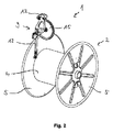
図1は、回転軸3周りに回動可能に取り付けられたスプール2が部分的に巻き取られた状態にある本発明の巻取装置1の概略断面図を示している。スプール2は、フランジ5を有するスプール本体4を備え、フランジ5は、スプール本体4の両端部に取り付けられている。
FIG. 1 shows a schematic cross-sectional view of a winding
巻取装置1は、スプール2のフランジ5の間に、円形断面を有する巻付可能材料のスプール巻取部をすでに部分的に形成している。巻付可能材料は、好ましくはワイヤであり、好ましくは8mmから30mmの直径を有する。
In the winding
スプール巻取部は、(図1において理想的な形態が描かれる)断面が六角形配置を形成する、個々の巻線部6の複数の層7からなる。 The spool take-up part consists of a plurality of layers 7 of individual winding parts 6 whose cross-section (in which the ideal form is depicted in FIG. 1) forms a hexagonal arrangement.
巻線部8は、最も外側の層7が巻き取られて当該ポイントにおいてさらに径方向外側に載るときに、すでに形成された巻線部を飛び越える“飛び越えている巻線部”の一例を表している。巻線部8の後に、3つのさらなる巻線部が最後に巻き取られた層7に適切に形成している。このような飛び越えている巻線部8は、スプールの巻取中に可能な限りどこでも防止されるべきであり、これは、不均一なスプールの巻取を引き起こすゆがみが後の層でさらに補強され、このことが全体として一様でない品質の悪いスプールのスプール巻取部と、対応して不十分なスプール充填率の程度と、をもたらす可能性があるためである。 The winding portion 8 represents an example of a “jumping winding portion” that jumps over the already formed winding portion when the outermost layer 7 is wound and placed further radially outward at that point. Yes. After the winding part 8, three further winding parts are suitably formed in the last wound layer. Such jumping windings 8 should be prevented as much as possible during the winding of the spool, which is further reinforced in later layers with distortions that cause uneven winding of the spool. This can result in a spool take-up portion of the overall poor quality spool and a correspondingly insufficient degree of spool fill.
巻取装置1は、スプール2の回転軸3と平行に配置されたスピンドル11に沿って変位可能なトラバース機構9を備えている。このために、スピンドル11は、モータ10によって回転され、これにより、外側ネジ山付きスピンドル11に変位可能に取り付けられ且つ対応する内側ネジ山(図示せず)を有するトラバースキャリッジ12がスピンドル11に沿って直線運動させられる。
The winding
トラバースキャリッジ12は、回転軸3及びスピンドル11に対して垂直に並べられたトラバースランス13に接続されている。トラバースランス13は、トラバースキャリッジ12に剛性接続された後方部13bと、スイベルジョイント14により後方部13bに回転可能に取り付けられた前方部13aと、からなり、回転は、トラバースランス13及び回転軸3を通って延びる平面で、すなわち(ジョイント14上に半円二重矢印によって示される)図1における投影平面で可能である。
The
巻付可能材料は、2つの偏向ローラ15を介してスプール巻取部にトラバースランス13に沿って供給される(明瞭にするために、巻付可能材料自体が、図1では描かれない)。左側の偏向ローラ15の最も外側の位置と最後の巻き取られた巻線部との間の距離、すなわち離脱ポイントと進行ポイントとの間の距離は、巻付可能材料の直径よりも一回り小さいことに留意されたい。機構(図示せず)が、例えば予め決定された角度だけスピンドル11周りに回動可能なトラバースランス13によって、この距離を調節するために採用することができる。
The wrappable material is fed along the
従って、トラバースランス13は、巻取プロセス中にスプール2の2つのフランジ5の間に入り込むが、巻取プロセスの初期にはフランジ5の間の領域内に回動させられるか、又は巻取プロセスの終わりにはフランジ5の外側に再び戻るように回動させることもそれぞれできる。従って、スプール2がトラバースランス13と衝突する可能性なくスプールを交換することが、困難なく提供される。
Thus, the
トラバースランス13の前方部13aと後方部13bとの間の角度は、トラバースランス13上でジョイント14に取り付けられたセンサ(図示せず)によって測定される。後方部13bが回転軸13に対して常に垂直であり、且つ前方部13aが巻付可能材料の進行軸の方向に延在しているので、前記角度は、巻付可能材料の進行角度に対応する。
The angle between the
トラバース速度、すなわち、測定された進行角度に応じて、スピンドル11の回転速度から生じるスピンドル11に沿うトラバースキャリッジ12の変位速度を適切に調節することによって、横断は、上述したようないかなる間隙の形成又は巻線部の飛び越えもなく、巻線部が互いに接触して位置するように制御される。
By appropriately adjusting the traverse speed, i.e. the displacement speed of the
所望の直線速度、すなわち巻付可能材料の供給量と、特定の時点でそれから生じるトラバース速度と、は、好ましくは、目標値として制御するために提供される。 The desired linear speed, i.e. the supply of wrappable material, and the traverse speed resulting therefrom at a particular point in time, are preferably provided for control as target values.
トラバース速度は、好ましくはリアルタイムで調節され、すなわちセンサデータは、制御手順がトラバース速度に影響を与えることのないように極めて迅速に処理される。 The traverse speed is preferably adjusted in real time, i.e. the sensor data is processed very quickly so that the control procedure does not affect the traverse speed.
これによって、制御手順は、巻付可能材料を正確な軌道に向けることを試みないように構成される。代わりに、トラバース機構9のみが、トラバースランス13がスプール巻取部のための最良な位置に常にあるように、測定された進行角度に基づいて調節される。すでに巻き取られた巻線部又は層ではなく、この現時点で巻き取られる巻線部の巻取のみが、再調節される。
Thereby, the control procedure is configured not to attempt to direct the wrappable material into the correct trajectory. Instead, only the traverse mechanism 9 is adjusted based on the measured advance angle so that the
第1、すなわち最も内側の層は、いかなる制御もなく、トラバース機構9の制御された変位のみによって、巻き取られていないスプールに形成される。 The first, i.e. innermost layer, is formed on the unwound spool by no controlled, only by the controlled displacement of the traverse mechanism 9.
さらに、1つ以上の適切な好ましい光センサ(図示せず)が、スプール2のフランジ5を検出することができ、このため、トラバース方向、すなわち回転軸3に沿うトラバース機構9の変位方向は、逆の方向で次の層を形成するために、フランジ5に達すると自動的に逆転する。しかしながら、この方向の変化は、トラバース機構9の移動経路に沿うフランジ5の位置に対応する一定の予め決定された切り替えポイントで生じることもできる。
In addition, one or more suitable preferred optical sensors (not shown) can detect the flange 5 of the
センサデータは、デジタル又はアナログ形態で記録することができる。さらに、外部の制御装置へのオープンインターフェースが、巻取装置1のフレキシブルな且つモジュール式の設計を可能にするために、巻取装置1に提供することができる。
Sensor data can be recorded in digital or analog form. Furthermore, an open interface to an external control device can be provided to the winding
図2は、図1においてのみ概略的に描かれたスプールが全く巻き取られていない状態にある本発明の巻取装置1の斜視図を示す。図3は、図2からのトラバース機構9の拡大詳細図を示す。参照符号は、図1のものと対応している。
FIG. 2 shows a perspective view of the winding
1 巻取装置、2 スプール、3 回転軸、4 スプール本体、5 フランジ、6 巻線部、7 層、8 飛び越えている巻線部、9 トラバース機構、10 モータ、11 スピンドル、12 トラバースキャリッジ、13 トラバースランス、13a トラバースランスの前方部、13b トラバースランスの後方部、14 ジョイント、15 偏向ローラ 1 winding device, 2 spool, 3 rotation shaft, 4 spool body, 5 flange, 6 winding part, 7 layers, 8 jumping winding part, 9 traverse mechanism, 10 motor, 11 spindle, 12 traverse carriage, 13 Traverse Lance, 13a Traverse Lance Front, 13b Traverse Lance Rear, 14 Joint, 15 Deflection Roller
Claims (7)
トラバース機構(9)であって、前記巻付可能材料が、前記トラバース機構(9)により、前記巻付可能材料が前記回転スプール(2)上のスプール巻取部に入る進行ポイントにガイドされ、且つ前記トラバース機構(9)が、前記回転スプール(2)の回転軸(3)の方向に実質的に移動可能である、トラバース機構(9)を備え、
前記回転スプール(2)の前記回転軸(3)に対して垂直な方向と、進行軸であって、前記巻付可能材料が、前記進行軸に沿って前記回転スプール(2)上の前記スプール巻取部上に入る、進行軸と、の間の前記巻付可能材料の進行角度を決定するための少なくとも1つのセンサをさらに備え、
前記巻取装置(1)が、巻取プロセス中の前記トラバース機構(9)の変位が前記少なくとも1つのセンサによって決定された前記進行角度に応じて調整されるように構成される、巻取装置(1)において、
前記巻付可能材料が前記トラバース機構(9)から離れる離脱ポイントと、前記進行ポイントと、の間の距離が、少なくとも断続的に、巻取プロセス中に前記巻付可能材料の直径の4倍未満であり、
前記トラバース機構(9)が、トラバースランス(13)を備えており、前記巻付可能材料が、前記トラバースランス(13)に沿って前記スプール巻取部(2)上の前記進行ポイントにガイドされ、
前記トラバースランス(13)自体が、前記進行軸を含み且つ前記回転スプール(2)の前記回転軸(3)と平行な平面において移動可能であり、
前記トラバースランス(13)が、複数のパーツの形態からなり、前記複数のパーツのうちの2つのパーツ(13a,13b)が、スイベルジョイント(14)によってともに回転可能に接続されており、前記少なくとも1つのセンサが、前記トラバースランス(13)の前記2つのパーツ(13a,13b)が互いに接続される、前記トラバースランス(13)のポイントに取り付けられることを特徴とする巻取装置(1)。 A winding device (1) for winding a wrappable material such as a strand onto a rotating spool (2),
A traverse mechanism (9), wherein the wrappable material is guided by the traverse mechanism (9) to an advancing point where the wrappable material enters a spool winding on the rotating spool (2); The traverse mechanism (9) includes a traverse mechanism (9) that is substantially movable in the direction of the rotation axis (3) of the rotary spool (2),
A direction perpendicular to the rotating shaft (3) of the rotating spool (2) and a traveling shaft, wherein the wrappable material is placed on the rotating spool (2) along the traveling shaft. At least one sensor for determining a travel angle of the wrappable material between a travel axis entering the winding portion;
The winding device (1) is configured such that the displacement of the traverse mechanism (9) during the winding process is adjusted according to the advance angle determined by the at least one sensor In (1),
The distance between the departure point where the wrappable material leaves the traverse mechanism (9) and the advance point is at least intermittently less than 4 times the diameter of the wrappable material during the winding process. And
The traverse mechanism (9) includes a traverse lance (13), and the wrappable material is guided along the traverse lance (13) to the advance point on the spool winding portion (2). ,
The traverse lance (13) itself is movable in a plane including the advancing axis and parallel to the rotational axis (3) of the rotary spool (2);
The traverse (13) is in the form of a plurality of parts, and two parts (13a, 13b) of the plurality of parts are rotatably connected together by a swivel joint (14), one sensor, wherein the two parts (13a, 13b) are connected to each other, the winding device comprising a fitted Turkey point of the traverse lance (13) of the traverse lance (13) (1 ).
前記離脱ポイントと前記進行ポイントとの間の距離が、少なくとも断続的に、前記巻取プロセス中に前記巻付可能材料の直径の4倍未満であることを特徴とする方法。 A method for winding a wrappable material such as a strand on a rotating spool (2) by means of a winding device (1) according to any one of claims 1 to 6,
The method, wherein the distance between the break-off point and the advance point is at least intermittently less than 4 times the diameter of the rewoundable material during the winding process.
Applications Claiming Priority (3)
| Application Number | Priority Date | Filing Date | Title |
|---|---|---|---|
| DE102014007552.4 | 2014-05-22 | ||
| DE102014007552.4A DE102014007552A1 (en) | 2014-05-22 | 2014-05-22 | Winding device for stranded winding material |
| PCT/EP2015/060960 WO2015177121A1 (en) | 2014-05-22 | 2015-05-19 | Winding device for strand-like material to be wound |
Publications (2)
| Publication Number | Publication Date |
|---|---|
| JP2017516727A JP2017516727A (en) | 2017-06-22 |
| JP6603674B2 true JP6603674B2 (en) | 2019-11-06 |
Family
ID=53276087
Family Applications (1)
| Application Number | Title | Priority Date | Filing Date |
|---|---|---|---|
| JP2016568878A Active JP6603674B2 (en) | 2014-05-22 | 2015-05-19 | Winding device for wrappable materials such as strands |
Country Status (11)
| Country | Link |
|---|---|
| US (1) | US10059560B2 (en) |
| EP (1) | EP3145846B1 (en) |
| JP (1) | JP6603674B2 (en) |
| CN (1) | CN106488879B (en) |
| DE (1) | DE102014007552A1 (en) |
| ES (1) | ES2748428T3 (en) |
| HU (1) | HUE046550T2 (en) |
| MX (1) | MX2016015108A (en) |
| PL (1) | PL3145846T3 (en) |
| RU (1) | RU2673730C2 (en) |
| WO (1) | WO2015177121A1 (en) |
Families Citing this family (8)
| Publication number | Priority date | Publication date | Assignee | Title |
|---|---|---|---|---|
| CN109775444B (en) * | 2017-11-10 | 2022-03-29 | 苏州凌犀物联网技术有限公司 | Remove spacing equipment |
| CN109775442A (en) * | 2017-11-10 | 2019-05-21 | 苏州凌犀物联网技术有限公司 | A kind of close strand winding apparatus in automatic Arrange-line System |
| CN107826848A (en) * | 2017-11-22 | 2018-03-23 | 正新橡胶(中国)有限公司 | A kind of band cord banding machine and its curl tension control device |
| CN107902479B (en) * | 2017-12-16 | 2023-07-04 | 橙色云互联网设计有限公司 | Winding and arranging system capable of adjusting incoming line angle |
| CN110002276A (en) * | 2019-01-21 | 2019-07-12 | 长春烽火技术有限公司 | A kind of cable auto take-up and its working method |
| CN112173864B (en) * | 2020-10-20 | 2022-03-01 | 温岭市新中禾机械有限公司 | Textile wire winding mechanism |
| CN112299276B (en) * | 2020-11-05 | 2022-10-25 | 庞华俊 | Electric hoist for hoisting equipment |
| CN112537693A (en) * | 2020-11-24 | 2021-03-23 | 杭州慧智新材料科技有限公司 | Traction incoming line angle reciprocating self-changing type wire-clamping-preventing wire winding device |
Family Cites Families (10)
| Publication number | Priority date | Publication date | Assignee | Title |
|---|---|---|---|---|
| GB1328542A (en) * | 1971-04-19 | 1973-08-30 | British Insulated Callenders | Apparatus for winding electric cables and the like |
| JPS516234U (en) * | 1974-07-03 | 1976-01-17 | ||
| AU495293B2 (en) * | 1974-08-27 | 1976-03-04 | Sumitomo Electric Industries, Ltd. | Automatic cable winding apparatus |
| CA1164851A (en) * | 1981-08-17 | 1984-04-03 | Ali Pan | Reeling of cable |
| DE3308283A1 (en) * | 1983-03-09 | 1984-09-20 | Fraunhofer-Gesellschaft zur Förderung der angewandten Forschung e.V., 8000 München | Device for winding cables or flexible lines onto drums |
| JP2621906B2 (en) * | 1988-02-25 | 1997-06-18 | 宇部日東化成株式会社 | Alignment winding device for linear objects |
| DE3827078A1 (en) | 1988-08-10 | 1990-02-15 | Hatlapa Uetersener Maschf | WINDING DEVICE FOR WINCHES |
| DE19508051A1 (en) | 1995-02-23 | 1996-08-29 | Hermann Jockisch | Coiling elongated material direction change point detection appts. |
| RU2392214C1 (en) * | 2009-01-27 | 2010-06-20 | Закрытое акционерное общество "Новатор" | Pickup of winding machine |
| CN203411163U (en) * | 2013-08-28 | 2014-01-29 | 象山科迪液压机械制造有限公司 | Winding machine |
-
2014
- 2014-05-22 DE DE102014007552.4A patent/DE102014007552A1/en active Pending
-
2015
- 2015-05-19 US US15/312,396 patent/US10059560B2/en active Active
- 2015-05-19 CN CN201580026633.2A patent/CN106488879B/en active Active
- 2015-05-19 WO PCT/EP2015/060960 patent/WO2015177121A1/en active Application Filing
- 2015-05-19 MX MX2016015108A patent/MX2016015108A/en unknown
- 2015-05-19 EP EP15726039.9A patent/EP3145846B1/en active Active
- 2015-05-19 PL PL15726039T patent/PL3145846T3/en unknown
- 2015-05-19 RU RU2016150090A patent/RU2673730C2/en active
- 2015-05-19 ES ES15726039T patent/ES2748428T3/en active Active
- 2015-05-19 JP JP2016568878A patent/JP6603674B2/en active Active
- 2015-05-19 HU HUE15726039A patent/HUE046550T2/en unknown
Also Published As
| Publication number | Publication date |
|---|---|
| HUE046550T2 (en) | 2020-03-30 |
| CN106488879B (en) | 2020-02-18 |
| RU2016150090A (en) | 2018-06-25 |
| JP2017516727A (en) | 2017-06-22 |
| US20170088389A1 (en) | 2017-03-30 |
| MX2016015108A (en) | 2017-03-27 |
| ES2748428T3 (en) | 2020-03-16 |
| EP3145846A1 (en) | 2017-03-29 |
| EP3145846B1 (en) | 2019-09-11 |
| PL3145846T3 (en) | 2020-02-28 |
| DE102014007552A1 (en) | 2015-11-26 |
| RU2673730C2 (en) | 2018-11-29 |
| CN106488879A (en) | 2017-03-08 |
| RU2016150090A3 (en) | 2018-09-28 |
| US10059560B2 (en) | 2018-08-28 |
| WO2015177121A1 (en) | 2015-11-26 |
Similar Documents
| Publication | Publication Date | Title |
|---|---|---|
| JP6603674B2 (en) | Winding device for wrappable materials such as strands | |
| KR102149074B1 (en) | Cable guide device for multi-diameter cables | |
| US11099345B2 (en) | Method of winding optical fiber, method of manufacturing bobbin-wound optical fiber, optical fiber winder, and method of manufacturing optical fiber strand | |
| TW201702169A (en) | Wire rod take-up device | |
| JP2010235332A (en) | Optical fiber reeling device and method for reeling optical fiber | |
| US9611124B2 (en) | Optical fiber screening test method and optical fiber screening test apparatus | |
| US20240010460A1 (en) | Low tension application coiler | |
| KR102135724B1 (en) | Winding apparatus | |
| JP5876158B2 (en) | Device comprising a rotating arm for unwinding a strand of material | |
| MX2022000983A (en) | Braiding, winding or spiralling machine, and method for operating same. | |
| JP2016044044A (en) | Delivery device of filament body and rewinding method of filament body | |
| US5390482A (en) | Apparatus and method for sending out linear material | |
| JP2621906B2 (en) | Alignment winding device for linear objects | |
| JP5225175B2 (en) | Cylindrical twisted yarn manufacturing apparatus and cylindrical twisted yarn manufacturing method using the apparatus | |
| JP7447378B2 (en) | Wire winding device and winding method | |
| JP7384177B2 (en) | Winding device and winding method | |
| JP6457203B2 (en) | Winding device | |
| WO2017116320A1 (en) | System and method for continuous strip winding onto lateral surface of longitudinal objects | |
| BR112016026977B1 (en) | WINDING DEVICE AND METHOD FOR WINDING A WIRE TYPE PRODUCT TO BE WINDED | |
| JP2023526589A (en) | Method and system for detecting lateral winding defects | |
| JPH05229733A (en) | Locking device of wire rod | |
| JP3449297B2 (en) | Method and apparatus for winding linear body on winding frame | |
| RU165157U1 (en) | DEVICE FOR STABILIZING WINDING SPEED OF FLEXIBLE LONG DIMENSIONAL MATERIAL | |
| KR100867165B1 (en) | Winder of packinging band and winding method thereof | |
| JPS6251874B2 (en) |
Legal Events
| Date | Code | Title | Description |
|---|---|---|---|
| A621 | Written request for application examination |
Free format text: JAPANESE INTERMEDIATE CODE: A621 Effective date: 20180508 |
|
| A977 | Report on retrieval |
Free format text: JAPANESE INTERMEDIATE CODE: A971007 Effective date: 20181105 |
|
| A131 | Notification of reasons for refusal |
Free format text: JAPANESE INTERMEDIATE CODE: A131 Effective date: 20181119 |
|
| A521 | Request for written amendment filed |
Free format text: JAPANESE INTERMEDIATE CODE: A523 Effective date: 20190214 |
|
| A131 | Notification of reasons for refusal |
Free format text: JAPANESE INTERMEDIATE CODE: A131 Effective date: 20190513 |
|
| A521 | Request for written amendment filed |
Free format text: JAPANESE INTERMEDIATE CODE: A523 Effective date: 20190730 |
|
| TRDD | Decision of grant or rejection written | ||
| A01 | Written decision to grant a patent or to grant a registration (utility model) |
Free format text: JAPANESE INTERMEDIATE CODE: A01 Effective date: 20190917 |
|
| A61 | First payment of annual fees (during grant procedure) |
Free format text: JAPANESE INTERMEDIATE CODE: A61 Effective date: 20191011 |
|
| R150 | Certificate of patent or registration of utility model |
Ref document number: 6603674 Country of ref document: JP Free format text: JAPANESE INTERMEDIATE CODE: R150 |
|
| R250 | Receipt of annual fees |
Free format text: JAPANESE INTERMEDIATE CODE: R250 |
|
| R250 | Receipt of annual fees |
Free format text: JAPANESE INTERMEDIATE CODE: R250 |