JP6603525B2 - sewing machine - Google Patents
sewing machine Download PDFInfo
- Publication number
- JP6603525B2 JP6603525B2 JP2015184915A JP2015184915A JP6603525B2 JP 6603525 B2 JP6603525 B2 JP 6603525B2 JP 2015184915 A JP2015184915 A JP 2015184915A JP 2015184915 A JP2015184915 A JP 2015184915A JP 6603525 B2 JP6603525 B2 JP 6603525B2
- Authority
- JP
- Japan
- Prior art keywords
- presser
- sewing machine
- cloth presser
- neutral
- height
- Prior art date
- Legal status (The legal status is an assumption and is not a legal conclusion. Google has not performed a legal analysis and makes no representation as to the accuracy of the status listed.)
- Active
Links
Images


Landscapes
- Sewing Machines And Sewing (AREA)
Description
本発明は、布押さえを昇降させる押さえ上げ機構を有するミシンに関する。 The present invention relates to a sewing machine having a press-up mechanism for raising and lowering a cloth presser.
従来のミシンは、布押さえを保持する押さえ棒と、押さえ棒を介して布押さえに下方の押さえ圧を付与する押さえバネと、押さえバネに抗して押さえ棒に上昇動作を付与するレバーと、複数のリンク体を介してレバーに上昇動作を付与するソレノイドとからなる押さえ上げ機構を備えている。
そして、布押さえを下降させる際には、ソレノイドを駆動しないか或いは推力を最小限として押さえバネのバネ圧により布押さえを行い、布押さえを上昇させる際には、ソレノイドを駆動して引き上げ動作を行っていた(例えば、特許文献1参照)。
The conventional sewing machine includes a press bar that holds the presser, a presser spring that applies a downward pressurizing pressure to the presser via the presser bar, a lever that applies an upward motion to the presser bar against the presser spring, A press-up mechanism including a solenoid that applies a lifting operation to the lever through a plurality of link bodies is provided.
When lowering the cloth presser, do not drive the solenoid, or press the cloth with the spring pressure of the presser spring while minimizing the thrust, and when raising the cloth presser, drive the solenoid to perform the lifting operation. (For example, refer to Patent Document 1).
しかしながら、上記従来のミシンは、布押さえの上昇動作駆動源としてソレノイドを使用しているので、布押さえの高さを任意に制御することが困難である。また、ソレノイドによる布押さえの昇降動作は、部材間の衝突が激しく、騒音が生じやすい、部材の損耗や破損が生じやすい等の問題が生じていた。
さらに、ソレノイドを布押さえの昇降動作の駆動源とする場合、布押さえの上昇中は電力を供給し続けて布押さえを維持しなければならないので、電力消費量が大きくなるという問題も生じていた。
However, since the conventional sewing machine uses a solenoid as a cloth presser raising operation drive source, it is difficult to arbitrarily control the height of the cloth presser. In addition, the lifting and lowering operation of the cloth presser by the solenoid causes problems such as strong collision between members, easy noise, and easy wear and damage of the members.
Furthermore, when the solenoid is used as a driving source for the lifting / lowering operation of the cloth presser, there is a problem that the power consumption is increased because the cloth presser must be maintained while the cloth presser is raised to maintain the cloth presser. .
本発明は、より良好な布押さえの昇降動作を行うことが可能なミシンを提供することをその目的とする。 An object of the present invention is to provide a sewing machine capable of performing a better fabric presser lifting operation.
請求項1記載の発明は、ミシンにおいて
回転式の外周カムと、
前記外周カムの外周に当接する従節体と、
前記従節体を介して回動し、布押さえに昇降動作を伝える伝達体と、
前記外周カムを回転させる押さえモーターと、
前記押さえモーターを制御して前記布押さえの昇降動作を制御する制御装置とを備えることを特徴とする。
さらに、請求項1記載の発明は、
前記外周カムは、一周の中に、押さえ位置と中間位置と押さえ上げ位置の三段階の前記布押さえの高さに個別に対応し、その外径がそれぞれ一定となる三つの中立区間と、これら三つの中立区間の間に設けられた三つの変化区間とを有し、
それぞれの前記変化区間は、外径が異なる両側の前記中立区間の一方の前記中立区間の外径から他方の前記中立区間の外径に徐々に移行するように外径が変化していることを特徴とする。
The invention according to
A follower that contacts the outer periphery of the outer cam;
A transmission body that rotates through the follower body and conveys the lifting operation to the cloth presser;
A holding motor for rotating the outer cam;
And a control device that controls the presser motor to control the lifting and lowering operation of the cloth presser.
Furthermore, the invention of
The outer peripheral cam individually corresponds to the height of the cloth presser in three stages of a press position, an intermediate position, and a press-up position, and has three neutral sections each having a constant outer diameter. Three change sections provided between the three neutral sections,
Each of the change sections has an outer diameter that gradually changes from the outer diameter of one of the neutral sections of the neutral sections on both sides having different outer diameters to the outer diameter of the other neutral section. Features.
請求項2記載の発明は、請求項1記載のミシンにおいて
前記布押さえの高さを入力操作によって指示入力する操作手段を備え、
前記制御装置が、前記布押さえが前記操作手段の入力操作量に応じた高さとなるように前記押さえモーターを制御することを特徴とする。
Invention of Claim 2 is provided with the operation means which instruct | indicates and inputs the height of the said cloth presser by input operation in the sewing machine of
The control device controls the presser motor so that the cloth presser has a height corresponding to an input operation amount of the operation means.
請求項3記載の発明は、請求項1又は2に記載のミシンにおいて
前記布押さえの高さを入力操作によって指示入力する操作手段を備え、
前記制御装置が、前記布押さえが前記操作手段の入力操作に応じて前記押さえ位置と前記中間位置と前記押さえ上げ位置のいずれかの高さとなるように前記押さえモーターを制御することを特徴とする。
Invention of Claim 3 is provided with the operation means which instruct | indicates and inputs the height of the said cloth presser by input operation in the sewing machine of
The control device controls the presser motor so that the cloth presser is at one of the press position, the intermediate position, and the press-up position according to an input operation of the operation means. .
請求項4記載の発明は、請求項1又は2に記載のミシンにおいて
前記布押さえの高さを入力操作によって指示入力する操作手段を備え、
前記制御装置は、
前記布押さえが前記操作手段の入力操作量に応じた高さとなるように前記押さえモーターを制御するリニア制御を実行することを特徴とする。
Invention of Claim 4 is equipped with the operation means which instruct | indicates and inputs the height of the said cloth presser by input operation in the sewing machine of
The controller is
Linear control for controlling the presser motor is executed so that the cloth presser has a height corresponding to an input operation amount of the operating means.
請求項5記載の発明は、請求項4記載のミシンにおいて
前記外周カムは、
前記三つの中立区間としての第一中立区間、第二中立区間及び第三中立区間と、
前記三つの変化区間としての第一変化区間、第二変化区間及び第三変化区間とを有しており、
前記制御装置は、
前記リニア制御として、前記押さえ位置から前記中間位置までの範囲における第一のリニア制御と、前記押さえ位置から前記押さえ上げ位置までの範囲における第二のリニア制御のいずれかを選択して実行すると共に、
前記第一のリニア制御の際には、前記外周カムの前記押さえ位置に対応する前記第一中立区間と前記中間位置に対応する前記第二中立区間との間の前記第一変化区間を使用し、
前記第二のリニア制御の際には、前記外周カムの前記押さえ位置に対応する前記第一中立区間と前記押さえ上げ位置に対応する前記第三中立区間との間の前記第三変化区間を使用するように前記押さえモーターを制御することを特徴とする。
The invention according to claim 5 is the sewing machine according to claim 4 , wherein the outer peripheral cam is:
A first neutral section, a second neutral section and a third neutral section as the three neutral sections;
The first change section, the second change section and the third change section as the three change sections,
The controller is
As the linear control, one of the first linear control in the range from the pressing position to the intermediate position and the second linear control in the range from the pressing position to the press-up position are selected and executed. ,
In the first linear control, the first change section between the first neutral section corresponding to the pressing position of the outer cam and the second neutral section corresponding to the intermediate position is used. ,
In the second linear control, the third change section between the first neutral section corresponding to the pressing position of the outer peripheral cam and the third neutral section corresponding to the pressing position is used. The presser motor is controlled as described above.
請求項6記載の発明は、請求項1から5のいずれか一項に記載のミシンにおいて
前記伝達体は、前記外周カムの回転中心側への回動により前記布押さえに下降動作を伝達し、
前記伝達体の前記外周カムの回転中心側への近接限界位置を調節することにより前記布押さえの下限位置を決定する調節手段を備えることを特徴とする。
The invention according to claim 6 is the sewing machine according to any one of
Adjusting means for determining a lower limit position of the cloth presser by adjusting a proximity limit position of the transmission body toward the rotation center side of the outer peripheral cam is provided.
本発明のミシンは、外周カムと押さえモーターとを備え、押さえモーターにより外周カムを回転させて布押さえの昇降動作を制御する制御装置を備えるので、布押さえを任意の高さに調節することが容易であり、縫製に関する種々の要請に対応して布押さえの高さ調節を行うことが可能となる。
また、布押さえの上下動を外周カムと押さえモーターとにより行うので、ソレノイドを駆動源とする場合のように二位置間での部材の移動による衝突や作動音が発生せず、静音化を図ると共に部材の損耗や破損の発生を低減することが可能となる。
また、外周カムを利用して布押さえの上下動を行うので、外周カムのカム形状の一部に回転中心から等径となる区間を設けた場合には、押さえモーターへの電源供給を低減又は停止しても従節体を一定の位置に保持することができるので、布押さえの上下動が行われ内題の電力消費量の低減を図ることが可能となる。
The sewing machine of the present invention includes an outer peripheral cam and a presser motor, and includes a control device that controls the lifting / lowering operation of the cloth presser by rotating the outer peripheral cam by the presser motor, so that the cloth presser can be adjusted to an arbitrary height. It is easy, and the height of the cloth presser can be adjusted in response to various demands related to sewing.
Further, since the cloth presser is moved up and down by the outer peripheral cam and the presser motor, there is no collision or operating noise caused by the movement of the member between the two positions as in the case where the solenoid is used as the drive source, and the noise is reduced. At the same time, it becomes possible to reduce the occurrence of wear and damage of the members.
In addition, since the cloth presser is moved up and down using the outer peripheral cam, the power supply to the presser motor is reduced or reduced when a section having the same diameter from the rotation center is provided in a part of the cam shape of the outer peripheral cam. Since the follower body can be held at a fixed position even when it is stopped, the cloth presser is moved up and down, and the power consumption of the subject can be reduced.
[発明の実施形態の概略]
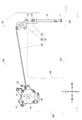
以下、図面を参照して、本発明にかかるミシンについて説明する。図1はミシンが有するミシンフレーム100と当該ミシンフレーム100内における押さえ上げ機構10の全体構成の配置を示す側面図である。
なお、本実施形態のミシンはいわゆる本縫いミシンであり、本発明の特徴的なミシンの押さえ上げ機構10について主に説明を行い、一般的な本縫いミシンが有する針上下動機構、布送り機構、釜機構、糸調子装置、天秤機構、糸切り装置については周知の構成と同一のものを備えているのでその説明は省略する。
[Outline of Embodiment of the Invention]
Hereinafter, a sewing machine according to the present invention will be described with reference to the drawings. FIG. 1 is a side view showing an arrangement of the entire structure of a
The sewing machine according to the present embodiment is a so-called lockstitch sewing machine. The sewing machine press-
また、以下の説明において、水平方向であって図1に示すミシンフレーム100のベッド部101の長手方向に沿った方向をY軸方向、水平方向であってY軸方向に直交する方向をX軸方向、鉛直上下方向をZ軸方向というものとする。また、必要に応じて、図1に示すように、Y軸方向における一方を「前」、他方を「後」とし、X軸方向における一方(図1の紙面奥側)を「左」、他方(図1の紙面手前側)を「右」とする。
In the following description, the horizontal direction along the longitudinal direction of the
ミシンフレーム100は、ミシン下部に延在するミシンベッド部101、当該ミシンベッド部101の後端部から立設された立胴部102、当該立胴部102の上端部から前方に延出されたミシンアーム部103とからなる。
ミシンベッド部101の前端部が針落ち位置となっており、その上面には針板104が装備されている。また、ミシンアーム部103の左端部には図示を省略した針棒が上下動可能な状態でZ軸方向に沿って支持されている。
The
A front end portion of the sewing
[押さえ上げ機構の概略構成]
押さえ上げ機構10は、布押さえ11と、布押さえ11を下端部で保持する押さえ棒12と、回転式の外周カム20と、外周カム20から布押さえ11に昇降動作を伝える伝達機構30と、外周カム20を回転させる押さえモーター14とを備えており、押さえモーター14はミシンの全体構成を制御する制御装置90によりその動作制御が行われる。
[Schematic configuration of presser foot lifting mechanism]
The
[布押さえ及び押さえ棒]
布押さえ11は、底面が平滑であって布送り方向上流側(手前側)が上方に反り上がったいわゆる舟形の押さえである。
押さえ棒12は、針棒の近傍においてZ軸方向に沿った状態でミシンアーム部103により上下動可能に支持されている。
押さえ棒12の上端部には棒抱き13が固定装備されている。押さえ棒12の上端部は棒抱き13を介して図示しない押さえバネにより下方に押圧されており、これにより押さえ圧を確保している。
また、棒抱き13は、右方に延出された角柱状の突起131を備えており、この突起131は後述するフック状の引き上げ板35に係止され、上方への引き上げ力が付与される。
[Cloth presser and presser bar]
The
The
A
Further, the
[伝達機構]
伝達機構30は、外周カム20の外周に当接する従節体としてのコロ31と、コロ31を支持する伝達体としての主動リンク32と、当該主動リンク32に連動する従動リンク33と、主動リンク32と従動リンク33を連結する連結棒34と、従動リンク33に連結されると共に棒抱き13を介して押さえ棒12及び布押さえ11を引き上げる引き上げ板35とを備えている。
[Transmission mechanism]
The
コロ31は主動リンク32によりX軸回りに回転可能に支持されており、外周カム20の外周の上部に当接するように配置されている。
主動リンク32は、いわゆるベルクランクであり、段ネジを軸としてX軸回りに回動可能にミシンフレーム100内に支持されている。この主動リンク32は、段ネジを中心とする半径方向外側に向かって二方向に二本の腕部を備えている。一方の腕部は後斜め下側に延出されると共にその先端部でコロ31を支持しており、他方の腕部は前斜め下側に延出されると共に連結棒34の一端部がX軸回りに回動可能に連結されている。
The
The
従動リンク33は、いわゆるベルクランクであり、図示しない支軸によりX軸回りに回動可能にミシンフレーム100内に支持されている。この従動リンク33は、支軸を中心とする半径方向外側に向かって二方向に二本の腕部を備えている。一方の腕部は前側に延出されると共にその先端部がX軸回りに回動可能に引き上げ板35の上端部に連結されており、他方の腕部は上側に延出されると共に連結棒34の他端部がX軸回りに回動可能に連結されている。
The driven
前述したように、布押さえ11及び押さえ棒12は、押さえバネによって下方に押圧されており、これによって、引き上げ板35を介して従動リンク33は図1における時計方向の回動力を受ける。さらに、主動リンク32は、連結棒34を介して反時計方向の回動力が付与され、コロ31は外周カム20の外周に圧接される。
As described above, the
[押さえモーター]
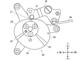
押さえモーター14は、出力軸がX軸方向に平行且つ左方を向いた状態で立胴部102内に支持されており、押さえモーター14の左側には外周カム20を支持する支持ブラケット15が組み付けられている。
支持ブラケット15は、図2に示すように、外周カム20の左右両側に配置された一対のブラケット板151,152とこれらブラケット板151,152の間に外周カム20を介挿させるために間隔をあけた状態で連結する三本の支柱153とから構成されている。そして、右側のブラケット板152が押さえモーター14に固定されている。
また、ブラケット板151,152の双方により、押さえモーター14が回転可能に支持されており、図示しないモーターベアリングの負荷を低減可能としている。
[Presser motor]
The holding
As shown in FIG. 2, the
Further, the holding
また、上記押さえモーター14と外周カム20と支持ブラケット15と後述する押さえモーター14の駆動回路142が形成された回路基板とが一体的にユニット化されている。
これにより、押さえモーター14及び外周カム20を備えていない従来のミシンに対しても、上記ユニットを容易に取り付けることができ、押さえモーター14により布押さえ11の高さ制御を行うことが可能なミシンに容易に改造することが可能となっている。
Further, the
Accordingly, the above-mentioned unit can be easily attached to a conventional sewing machine that is not provided with the
[外周カム]
外周カム20には、前述したように主動リンク32に支持されたコロ31が圧接しているので、その回転中心から外周までの距離(以下、変位という)の変動により主動リンク32を回動させることができる。前述した伝達機構30の構成の場合、外周カム20の変位が小さければ布押さえ11は下降し、外周カム20の変位が大きければ布押さえ11は上昇する。
[Outer peripheral cam]
As described above, the
そして、外周カム20は、図3に示すように、一周の中に、「押さえ位置」,「中間位置」,「押さえ上げ位置」の三段階の布押さえ11の高さに個別に対応三つの中立区間である第一中立区間21,第二中立区間22,第三中立区間23と、これら第一中立区間21,第二中立区間22,第三中立区間23の間に設けられた三つの変化区間である第一変化区間24,第二変化区間25,第三変化区間26とを有している。
As shown in FIG. 3, the outer
上記「押さえ位置」は、布押さえ11が針板104に到達し、針板104の上の被縫製物を押さえること可能な高さであり、「中間位置」及び「押さえ上げ位置」よりも低い位置となる。
上記「中立位置」は、布押さえ11が針板104から幾分上方に離れた高さであり、例えば、縫い針が被縫製物に刺さったままの状態で向きを変える等の作業を行う場合に、布押さえ11による押さえ圧を解除するための高さである。この「中間位置」は、「押さえ位置」と「押さえ上げ位置」の間の高さとなる。
上記「押さえ上げ位置」は、布押さえ11が針板104から十分上方に離れた高さであり、例えば、縫製終了後の被縫製物の撤去、交換等の作業の妨げとならないように布押さえ11を退避させる高さである。この「押さえ上げ位置」は「押さえ位置」及び「中間位置」よりも高い位置となる。
The “pressing position” is a height at which the
The “neutral position” is a height at which the
The above-mentioned “pressing up position” is a height at which the
上記第一中立区間21,第二中立区間22,第三中立区間23は、いずれも、その外周の変位が一定となるように形成されている。そして、「押さえ位置」に対応する第一中立区間21はその変位が最も小さく、「中間位置」に対応する第二中立区間22はその変位が二番目に小さく、「押さえ上げ位置」に対応する第三中立区間23はその変位が最も大きい。
また、図3に示すように、第一中立区間21に対して第二中立区間22は反時計方向に位置し、第一中立区間21に対して第三中立区間23は時計方向に位置している。
なお、三つの中立区間21,22,23の角度幅は、三つの変化区間24,25,26に比べて狭くすることが望ましい。但し、少なくとも、押さえモーター14の駆動を停止した状態でコロ31が各中立区間21,22,23の外周に当接した状態を維持することが可能な程度の幅を有することが望ましい。
The first
Further, as shown in FIG. 3, the second
It should be noted that the angle widths of the three
三つの変化区間24,25,26は、三つの中立区間21,22,23の間に個別に設けられている。
そして、第一変化区間24は、第一中立区間21の外径から第二中立区間22の外径に徐々に移行するように外径が変化している。
また、第二変化区間25は、第二中立区間22の外径から第三中立区間23の外径に徐々に移行するように外径が変化している。
また、第三変化区間26は、第三中立区間23の外径から第一中立区間21の外径に徐々に移行するように外径が変化している。
また、図3に示すように、第一変化区間24に対して第二変化区間25は反時計方向に位置し、第一変化区間24に対して第三変化区間26は時計方向に位置している。
The three
The first changing
Further, the outer diameter of the
Further, the outer diameter of the
In addition, as shown in FIG. 3, the
[ミシンの制御系]
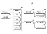
図4に押さえ上げ機構10を備えるミシンの制御系のブロック図を示す。
ミシンは、その構成の動作制御を行う制御装置90を備え、当該制御装置90に対して、布押さえ11の昇降動作の駆動源となる押さえモーター14及びその出力軸角度を検出するエンコーダー141、縫製動作の駆動源となるミシンモーター16及びその出力軸角度を検出するエンコーダー161がそれぞれの駆動回路142、162を介して接続されている。
また、制御装置90に対して、縫製終了時に上糸及び下糸を切断する糸切り装置17、作業者がミシンに対する操作入力を行う操作手段としての操作ペダル18からの操作量を検出するペダルセンサー181が接続されている。
[Sewing machine control system]
FIG. 4 shows a block diagram of a control system of a sewing machine provided with the press-up
The sewing machine includes a
In addition, a
制御装置90は、ミシンの押さえ上げ機構10の各部の制御及び演算処理を行うCPU91と、CPU91の作業エリアとなるRAM92と、CPU91が処理するプログラムが記憶されたROM93と、演算処理に用いられるデータが記憶されるとともに当該データを書き換え可能に構成された記憶部としてのEEPROM94とを備えている。
The
図5は操作ペダル18の前踏み量(図5における時計方向の回動角度)と後踏み量(図5における反時計方向の回動角度)と入力操作の割り当てとの関係について示す説明図である。
操作ペダル18は、図5に実線で示す傾斜角度を中立位置としており、作業者が操作を行っていない状態ではこの中立位置に復帰するようにバネ圧が付与されている。
FIG. 5 is an explanatory diagram showing the relationship between the amount of forward depression of the operation pedal 18 (clockwise rotation angle in FIG. 5), the amount of rear depression (counterclockwise rotation angle in FIG. 5), and assignment of input operations. is there.
The
そして、ペダルセンサー181は、中立位置を0として、前踏みにおける最大踏み込み量をPf、後踏みにおける最大踏み込み量をPeとして出力を行う。これらの最大踏み込み量は、操作ペダル18の物理的な踏み込みの限界位置と一致する。なお、前踏みと後踏みでは、ペダルセンサー181が出力する検出値の極性は互いに逆となっている。
そして、制御装置90は、操作ペダル18の踏み込み量0〜Pfまでの前踏みの範囲では、ミシンモーター16を駆動して縫製を行う。また、この踏み込み量0〜Pfの範囲では、踏み込み量に応じてミシンモーター16の速度制御を行う。
また、制御装置90は、縫製途中において操作ペダル18の踏み込み量0(中立位置)が検出された場合には、針棒下位置(縫い針が被縫製物に刺さった状態)でミシンモーター16を停止させる制御を行う。
さらに、ペダルセンサー181が中立位置及び前踏みの範囲内では、制御装置90は、布押さえ11を押さえ位置に下ろした状態とする制御を行う。
Then, the
Then, the
Further, when the depression amount 0 (neutral position) of the
Further, when the
一方、制御装置90は、操作ペダル18の後踏みについては、後述する「縫製途中」か否かによって、実行する動作が異なっている。
即ち、ミシンが縫製途中の状態では、制御装置90は、操作ペダル18の後踏みの踏み込み量が0を超えてPn未満の範囲では、踏み込み量に応じた布押さえ11の高さ制御を実行し、踏み込み量がPn以上となると、糸切り装置17による糸切りを実行する。
また、ミシンが縫製途中ではない場合には、制御装置90は、操作ペダル18の後踏みの踏み込み量が0を超えてPeまでの全範囲で、踏み込み量に応じた布押さえ11の高さ制御を実行する。
On the other hand, the
That is, when the sewing machine is in the middle of sewing, the
When the sewing machine is not in the middle of sewing, the
なお、制御装置90による、ミシンが縫製途中であるか否かの判断は、ミシンモーター16の駆動履歴と糸切り装置17の糸切り動作の実行の履歴とから行う。
即ち、ミシンの主電源の投入後、ミシンモーター16の駆動が行われるまでは「非縫製途中状態」と判断され、一回転でもミシンモーター16の駆動が行われると「縫製途中状態」となる。その後は、糸切りが実行されると、「縫製途中状態」が解除されて「非縫製途中状態」となり、一回転でもミシンモーター16の駆動が行われると「縫製途中状態」となる。その後は、主電源が落とされるまで、制御装置90によって、同様の判断が行われる。
The
That is, after the main power of the sewing machine is turned on, it is determined that the
[押さえ上げ機構の動作制御]
上記制御装置90のCPU91による押さえ上げ機構10を主体とするミシンの動作制御について図6のフローチャートに基づいて詳細に説明する。
まず、ミシンの主電源が投入されると、制御装置90のCPU91は、ミシンが縫製途中状態か否かを判定する(ステップS1)。前述したように、CPU91は、ミシンモーター16の駆動履歴と糸切り装置17の実行履歴とから判断を行う。
[Operation control of the lifting mechanism]
The operation control of the sewing machine mainly composed of the press-up
First, when the main power of the sewing machine is turned on, the
具体的には、主電源投入後又は糸切りの実行後にミシンモーター16の駆動が全く行われていない場合には、「非縫製途中状態」と判断し(ステップS1:NO)、CPU91は、操作ペダル18の後踏みの踏み込み量0〜Peまでの全範囲を布押さえ11の高さ制御に割り当てる。この時、踏み込み量0で「押さえ位置」、踏み込み量Peで「押さえ上げ位置」となり、これらの間については踏み込み量に応じて比例的に布押さえ11の高さが増減するように割り当てを行う。
そして、CPU91は、上記割り当てに基づいてペダルセンサー181の検出した踏み込み量Pbに対応する布押さえ11の高さを求め、当該高さとなる様に押さえモーター14の回転を制御する(ステップS19)。
そして、処理をステップS1に戻す。
Specifically, when the
Then, the
Then, the process returns to step S1.
なお、上記ステップS19の高さ調節制御は「第二のリニア制御」に相当する。第二のリニア制御では、ペダル操作に応じて、布押さえ11の高さを「押さえ位置」から「押さえ上げ位置」の範囲で任意且つリニアに制御するので、CPU91は、外周カム20の第三変化区間26にコロ31が当接するように押さえモーター14を制御する。
The height adjustment control in step S19 corresponds to “second linear control”. In the second linear control, the height of the
一方、ミシンが縫製途中か否かの判定において、主電源投入後又は糸切りの実行後にミシンモーター16の駆動が一回転でも行われていた場合には、「縫製途中状態」と判断し(ステップS1:YES)、CPU91は、操作ペダル18の後踏みの踏み込み量0〜Pnの範囲を布押さえ11の高さ制御に割り当て、踏み込み量Pnを超える範囲を糸切り装置17による糸切りの実行指示に割り当てる。
さらに、CPU91は、上記割り当てに基づいてペダルセンサー181の検出した踏み込み量Pbが0<Pb≦Pnの範囲内か否かを判定する(ステップS3)。
On the other hand, in the determination of whether the sewing machine is in the middle of sewing, if the
Further, the
そして、踏み込み量Pbが0<Pb≦Pnの範囲内である場合には(ステップS3:YES)、ミシンモーター16のエンコーダー161の検出信号から現在の縫い針の先端部が針板上面よりも下に位置する針棒下位置であるか否かを判定する(ステップS5)。
When the stepping amount Pb is within the range of 0 <Pb ≦ Pn (step S3: YES), the tip of the current sewing needle is below the upper surface of the needle plate from the detection signal of the
上記判定において、針棒下位置と判定した場合には(ステップS5:YES)、CPU91は、踏み込み量0では「押さえ位置」、踏み込み量Pnでは「中間位置」を割り当て、これらの間の踏み込み量については踏み込み量に応じて比例的に布押さえ11の高さが増減するように割り当てを行う。そして、上記割り当てに基づいてペダルセンサー181の検出した踏み込み量Pbに対応する布押さえ11の高さを求め、当該高さとなる様に押さえモーター14の回転を制御する(ステップS7)。
そして、処理をステップS1に戻す。
In the above determination, if it is determined that the needle bar is in the lower position (step S5: YES), the
Then, the process returns to step S1.
なお、上記ステップS7の高さ調節制御は「第一のリニア制御」に相当する。第一のリニア制御では、ペダル操作に応じて、布押さえ11の高さを「押さえ位置」から「中間位置」の範囲で任意且つリニアに制御するので、CPU91は、外周カム20の第一変化区間24にコロ31が当接するように押さえモーター14を制御する。
Note that the height adjustment control in step S7 corresponds to “first linear control”. In the first linear control, the height of the
上記ステップS7の布押さえ11の高さ制御の意義について補足的に説明する。
ステップS7は、ミシンが縫製途中であって、ペダル後踏みの踏み込み量Pbは0<Pb≦Pnの範囲内であること、針棒が針棒下位置にあることを前提とする。
ミシンが縫製途中であるということは、針板上に被縫製物が存在し、縫製が現在実行中であることを示す。
ペダル後踏みの踏み込み量Pbが0<Pb≦Pnの範囲内であるということは、ミシンの使用者は、布押さえ11の高さを調節しようとしていることを示す
そして、針棒が針棒下位置にあるということは、縫い針が被縫製物に突き刺さった状態で停止していることを示す。
つまり、ステップS7に至る場合には、ミシンの使用者は、縫製途中で縫いを停止し、縫い針が突き刺さったままの状態で布押さえ11を押さえ位置より上に上昇させようとしており、一般には、被縫製物の向きを変える等の作業を行おうとしている状況にある可能性が高いことを意味している。
従って、このような場合には、制御装置90は、布押さえ11の高さ調節範囲を「押さえ位置」から「中間位置」までの範囲内で操作ペダル18によってリニア制御を行うことを可能とし、過剰に布押さえ11が上昇することなく、適度な範囲で任意に布押さえ11の高さ調節することができるように制御を行う。
The significance of the height control of the
Step S7 is based on the premise that the sewing machine is in the middle of sewing, the depression amount Pb of the pedal after stepping is within the range of 0 <Pb ≦ Pn, and the needle bar is in the lower position of the needle bar.
The fact that the sewing machine is in the middle of sewing indicates that there is an object to be sewn on the needle plate and sewing is currently being executed.
The fact that the pedal depression amount Pb is within the range of 0 <Pb ≦ Pn indicates that the sewing machine user wants to adjust the height of the
In other words, when reaching step S7, the user of the sewing machine stops sewing in the middle of sewing, and tries to raise the
Accordingly, in such a case, the
一方、ステップS5の判定において、針棒下位置ではないと判定した場合には、(ステップS5:NO)、CPU91は、踏み込み量0では「押さえ位置」、踏み込み量Pnでは「押さえ上げ位置」を割り当て、これらの間の踏み込み量については踏み込み量に応じて比例的に布押さえ11の高さが増減するように割り当てを行う。そして、上記割り当てに基づいてペダルセンサー181の検出した踏み込み量Pbに対応する布押さえ11の高さを求め、当該高さとなる様に押さえモーター14の回転を制御する(ステップS9)。
そして、処理をステップS1に戻す。
On the other hand, if it is determined in step S5 that the position is not the needle bar lower position (step S5: NO), the
Then, the process returns to step S1.
なお、上記ステップS9の高さ調節制御は「第二のリニア制御」に相当する。第二のリニア制御では、ペダル操作に応じて、布押さえ11の高さを「押さえ位置」から「押さえ上げ位置」の範囲で任意且つリニアに制御するので、CPU91は、外周カム20の第三変化区間26にコロ31が当接するように押さえモーター14を制御する。
The height adjustment control in step S9 corresponds to “second linear control”. In the second linear control, the height of the
上記ステップS9の布押さえ11の高さ制御の意義について補足的に説明する。
ステップS9は、ミシンが縫製途中であって、ペダル後踏みの踏み込み量Pbは0<Pb≦Pnの範囲内であること、針棒が針棒下位置にはないことを前提とする。
つまり、ステップS9に至る場合には、ミシンの使用者は、縫製途中で縫いを停止し、縫い針が突き刺さっていない状態で布押さえ11を押さえ位置より上に上昇させようとしている。通常は、縫製途中で縫いを停止した場合には、制御装置90は、針棒が針棒下位置となるようにミシンモーター16を停止させる制御を行うが、それにも拘わらず、針棒が針棒下位置にないということは、人為的にプーリを回して針棒を上昇させた可能性が高いことを意味している。これには種々の要因が考えられるが、少なくとも針棒を針棒下位置よりも上に上昇させているということは、縫い針が作業の妨げになるので退避させていることが予想される。
従って、このような場合には、制御装置90は、布押さえ11の高さ調節範囲を「押さえ位置」から「押さえ上げ位置」までの範囲内で操作ペダル18によってリニア制御を行うことを可能とし、布押さえ11を十分に上方に退避させることが可能な範囲で任意に高さ調節することができるように制御を行う。
The significance of the height control of the
Step S9 is based on the premise that the sewing machine is in the middle of sewing, the depression amount Pb of the step after the pedal is within the range of 0 <Pb ≦ Pn, and the needle bar is not in the lower position of the needle bar.
That is, when reaching step S9, the user of the sewing machine stops sewing in the middle of sewing, and tries to raise the
Therefore, in such a case, the
また、ステップS3の判定において、ペダルの踏み込み量Pbが0<Pb≦Pnの範囲内ではないと判定した場合には(ステップS3:NO)、ペダルの踏み込み量PbがPb>Pnであるか否かを判定する(ステップS11)。
そして、ペダルの踏み込み量PbがPb>Pnである場合には(ステップS11:YES)、糸切りの実行の指示入力であると判断して、布押さえ11を押さえ位置まで下降させるように押さえモーター14を制御して(ステップS13)、さらに、糸切り装置17により糸切り動作を実行させる(ステップS15)。
そして、処理をステップS1に戻す。
If it is determined in step S3 that the pedal depression amount Pb is not within the range of 0 <Pb ≦ Pn (step S3: NO), whether or not the pedal depression amount Pb is Pb> Pn. Is determined (step S11).
If the pedal depression amount Pb is Pb> Pn (step S11: YES), it is determined that it is an instruction input to execute thread trimming, and a presser motor is used to lower the
Then, the process returns to step S1.
一方、ステップS11において、ペダルの踏み込み量PbがPb>Pnではないと判定した場合には(ステップS11:NO)、操作ペダル18は中立位置か前踏みの範囲内(0≦Pb≦Pf)であることを意味するので、布押さえ11を押さえ位置まで下降させるように押さえモーター14を制御して(ステップS17)、ミシンモーター16を停止又は踏み込み量に応じた速度で駆動させる。
そして、処理をステップS1に戻す。
On the other hand, if it is determined in step S11 that the pedal depression amount Pb is not Pb> Pn (step S11: NO), the
Then, the process returns to step S1.
[発明の実施形態の技術的効果]
押さえ上げ機構10は、外周カム20と従節体としてのコロ31と伝達体としての主動リンク32と押さえモーター14とを備え、ミシンは、押さえモーター14を制御して布押さえ11の昇降動作を制御する制御装置90を備えるので、布押さえ11を任意の高さに調節することが容易であり、縫製に関する種々の要請に対応して布押さえ11の高さ調節を行うことが可能となる。
また、布押さえ11の上下動を外周カム20と押さえモーター14とにより行うので、ソレノイドを駆動源とする場合のように二位置間での部材の移動による衝突や作動音が発生せず、静音化を図ると共に部材の損耗や破損の発生を低減することが可能となる。
[Technical effects of the embodiment of the invention]
The
Further, since the
また、上記ミシンは、布押さえ11の高さを入力操作によって指示入力する操作手段としてのペダルを備え、制御装置90が、布押さえ11がペダルの入力操作量に応じた高さとなるように押さえモーター14を制御するので、例えば、縫製中であっても、容易に、布押さえ11の高さ調節を行うことが可能となる。
Further, the sewing machine includes a pedal as an operation means for inputting an instruction to input the height of the
また、外周カム20は、一周の中に、押さえ位置と中間位置と押さえ上げ位置の布押さえ11の高さに個別に対応する三つの中立区間21,22,23とを有するので、各中立区間21,22,23にコロ31が当接した状態で押さえモーター14の電源供給を低減又は停止しても、布押さえ11をそれらの各中立区間に対応した布押さえ11の高さに維持することができ、電力消費量の低減を図ることが可能となる。
また、三つの変化区間24,25,26との間で漸減的又は漸増的に外周が変化した三つの変化区間24,25,26とを有するので、押さえ位置と中間位置と押さえ上げ位置の各位置間での高さ調節を円滑に行うことが可能となる。
Moreover, since the outer
In addition, since there are three
また、制御装置90は、外周カム20の回転により、布押さえ11が操作ペダル18の入力操作量に応じた高さとなるように押さえモーター14を制御する第一又は第二のリニア制御を実行するので、布押さえ11を、押さえ位置と中間位置と押さえ上げ位置の各位置の間の任意の高さにも容易に調節することが可能となる。
Further, the
さらに、制御装置90は、前述したステップS7,S9,S19において、押さえ位置から中間位置までの範囲における第一のリニア制御と、押さえ位置から押さえ上げ位置までの範囲における第二のリニア制御とを選択して実行すると共に、第一のリニア制御の際には、外周カム20の押さえ位置に対応する第一中立区間21と中間位置に対応する第二中立区間22との間の第一変化区間24を使用し、第二のリニア制御の際には、外周カム20の押さえ位置に対応する第一中立区間21と押さえ上げ位置に対応する第三中立区間23との間の第三変化区間26を使用するように押さえモーター14を制御している。
このため、第一及び第二のリニア制御の調節範囲内において布押さえ11の高さを漸増的又は漸減的に変化させる際に、いずれかの中立区間とコロ31とが当接する状態の発生を回避することができるので、途中で停止することなく、布押さえ11を円滑に昇降させることが可能となる。
Further, the
For this reason, when the height of the
[押さえ上げ機構の動作制御の他の例]
図6に示した押さえ上げ機構10の動作制御では、ステップS7,S9,S19において、布押さえ11の高さについてリニア制御を実施しているが、これらは、押さえ位置と中間位置と押さえ上げ位置のいずれかの高さとなるように高さを段階的に調節する制御を行っても良い。
例えば、図6のステップS7では布押さえ11が中間位置となる様に押さえモーター14を制御し、ステップS9では布押さえ11が押さえ上げ位置となる様に押さえモーター14を制御し、ステップS19では布押さえ11が押さえ上げ位置となる様に押さえモーター14を制御しても良い。
これにより、外周カム20の三つの中立区間21,22,23の内のいずれかにコロ31を当接させることができ、その間は押さえモーター14への電源供給を低減又は停止することができるので、ミシンの電力消費を低減することが可能となる。
[Another example of operation control of the presser mechanism]
In the operation control of the press-up
For example, in step S7 of FIG. 6, the
Thereby, the
[微小押さえ上げの調節手段]
押さえ上げ機構10には、図7に示すように、微小押さえ上げの調節手段40を付加しても良い。
調節手段40は、伝達体としての主動リンク32の外周カム20の回転中心側への近接限界位置を調節することにより布押さえ11の下限位置を決定するためのものであり、例えば、ミシンフレームに設けられたZ軸方向に沿ったネジ穴41と当該ネジ穴41に螺合する調節ネジ42とからなる。
調節ネジ42は、その下端部が主動リンク32との当接端部となり、上端部は回転操作を行うための頭部となっている。頭部は手動で回転操作を行うためにローレット加工を施す、或いは、工具で回転操作を行うために外周が六角形状又は上端面に六角穴を設けてもよい。
調節ネジ42の下端部は、主動リンク32のコロ31を保持していない方の腕部に対して上方から当接し、調節ネジ42を回転操作することにより主動リンク32が時計周りに回動し、コロ31が外周カム20から離間する方向へ移動させることができる。
この調節手段40により、コロ31が外周カム20の回転中心側に最も近接する位置を当該回転中心に対して離間させることができ、その離間移動量に応じて、布押さえ11の下限位置(通常は押さえ位置が下限位置となっている)を押さえ位置よりも上方に移動調節することができる。
例えば、厚地の被縫製物に対して、布押さえ11の下限位置を押さえ位置よりも幾分上方、例えば、布厚よりも若干狭い隙間が生じる程度にシフトさせることにより、厚地の被縫製物を良好に送ることが可能となる。いわゆる、微小押さえ上げの調節が可能となる。
[Adjustment means for minute press-up]
As shown in FIG. 7, the press-up
The adjusting means 40 is for determining the lower limit position of the
The
The lower end portion of the
By this adjusting means 40, the position where the
For example, by shifting the lower limit position of the
[その他]
なお、上記ミシンでは、布押さえ11の上下動を糸切り装置と連動するように動作制御を行っているが(図6のステップS13及びS14)、布押さえ11の上下動のミシンの他の構成と連動させても良い。
例えば、針板の下側で縫製開始時の上糸の縫い開始端部を保持する糸掴み装置を備えるミシンに上記押さえ上げ機構10を装備した場合には、糸掴み装置が上糸の縫い開始端部を保持するタイミングで布押さえ11を一時的に上方に移動させて上糸が布押さえ11に押さえられないようにして、糸掴み装置が掴んだ上糸引き寄せる動作を円滑に行えるように構成してもよい。
[Others]
In the above-described sewing machine, the movement control is performed so that the vertical movement of the
For example, when the above-described
また、ミシンの回転数や上軸角度に応じて押さえ上げ機構10を連動させて、所定の針数で又は所定の上軸角度で布押さえ11を上昇させて被縫製物を解放する動作制御等も行うことが可能である。
In addition, the press-up
また、上記ミシンでは外周カムを挟むよう支持する一対のブラケット151,152を設け、その内の一方のブラケット152で押さえモーター14を固定する構成としたが、十分に剛性のあるモーター軸、及びモーターベアリングを用いることによって、支持ブラケット板151と三本の支柱153を省略し、ブラケット152のみによる片持ち支持の構成とすることも可能である。
In the above-described sewing machine, a pair of
10 押さえ上げ機構
11 布押さえ
14 押さえモーター
15 支持ブラケット
16 ミシンモーター
17 糸切り装置
18 操作ペダル
20 外周カム
21,22,23 中立区間
24,25,26 変化区間
30 伝達機構
31 コロ(従節体)
32 主動リンク(伝達体)
40 調節手段
42 調節ネジ
90 制御装置
100 ミシンフレーム
DESCRIPTION OF
32 Main link (transmitter)
40 adjusting means 42 adjusting
Claims (6)
前記外周カムの外周に当接する従節体と、
前記従節体を介して回動し、布押さえに昇降動作を伝える伝達体と、
前記外周カムを回転させる押さえモーターと、
前記押さえモーターを制御して前記布押さえの昇降動作を制御する制御装置とを備え、
前記外周カムは、一周の中に、押さえ位置と中間位置と押さえ上げ位置の三段階の前記布押さえの高さに個別に対応し、その外径がそれぞれ一定となる三つの中立区間と、これら三つの中立区間の間に設けられた三つの変化区間とを有し、
それぞれの前記変化区間は、外径が異なる両側の前記中立区間の一方の前記中立区間の外径から他方の前記中立区間の外径に徐々に移行するように外径が変化していることを特徴とするミシン。 A rotary outer cam;
A follower that contacts the outer periphery of the outer cam;
A transmission body that rotates through the follower body and conveys the lifting operation to the cloth presser;
A holding motor for rotating the outer circumferential cam;
A controller for controlling the presser motor to control the lifting operation of the cloth presser ,
The outer circumferential cam has three neutral sections each corresponding to the height of the cloth presser in three stages of a press position, an intermediate position, and a press-up position, each of which has a constant outer diameter. And three change sections provided between three neutral sections,
Each of the change sections has an outer diameter that gradually changes from the outer diameter of one of the neutral sections on the opposite sides of the neutral section, which has different outer diameters, to the outer diameter of the other neutral section. Characteristic sewing machine.
前記制御装置が、前記布押さえが前記操作手段の入力操作量に応じた高さとなるように前記押さえモーターを制御することを特徴とする請求項1記載のミシン。 Comprising an operation means for inputting an instruction for the height of the cloth presser by an input operation;
The sewing machine according to claim 1, wherein the control device controls the presser motor so that the cloth presser has a height corresponding to an input operation amount of the operation means.
前記制御装置が、前記布押さえが前記操作手段の入力操作に応じて前記押さえ位置と前記中間位置と前記押さえ上げ位置のいずれかの高さとなるように前記押さえモーターを制御することを特徴とする請求項1又は2に記載のミシン。 Comprising an operation means for inputting an instruction for the height of the cloth presser by an input operation;
The control device controls the presser motor so that the cloth presser is at one of the press position, the intermediate position, and the press-up position according to an input operation of the operation means. The sewing machine according to claim 1 or 2 .
前記制御装置は、
前記布押さえが前記操作手段の入力操作量に応じた高さとなるように前記押さえモーターを制御するリニア制御を実行することを特徴とする請求項1又は2に記載のミシン。 Comprising an operation means for inputting an instruction for the height of the cloth presser by an input operation;
The controller is
3. The sewing machine according to claim 1 , wherein linear control is performed to control the presser motor so that the cloth presser has a height corresponding to an input operation amount of the operating means.
前記三つの中立区間としての第一中立区間、第二中立区間及び第三中立区間と、
前記三つの変化区間としての第一変化区間、第二変化区間及び第三変化区間を有しており、
前記制御装置は、
前記リニア制御として、前記押さえ位置から前記中間位置までの範囲における第一のリニア制御と、前記押さえ位置から前記押さえ上げ位置までの範囲における第二のリニア制御のいずれかを選択して実行すると共に、
前記第一のリニア制御の際には、前記外周カムの前記押さえ位置に対応する前記第一中立区間と前記中間位置に対応する前記第二中立区間との間の前記第一変化区間を使用し、
前記第二のリニア制御の際には、前記外周カムの前記押さえ位置に対応する前記第一中立区間と前記押さえ上げ位置に対応する前記第三中立区間との間の前記第三変化区間を使用するように前記押さえモーターを制御することを特徴とする請求項4記載のミシン。 The outer peripheral cam is
A first neutral section, a second neutral section and a third neutral section as the three neutral sections;
The first change section, the second change section and the third change section as the three change sections,
The controller is
As the linear control, one of the first linear control in the range from the pressing position to the intermediate position and the second linear control in the range from the pressing position to the press-up position are selected and executed. ,
In the first linear control, the first change section between the first neutral section corresponding to the pressing position of the outer cam and the second neutral section corresponding to the intermediate position is used. ,
In the second linear control, the third change section between the first neutral section corresponding to the pressing position of the outer peripheral cam and the third neutral section corresponding to the pressing position is used. The sewing machine according to claim 4 , wherein the presser motor is controlled to do so.
前記伝達体の前記外周カムの回転中心側への近接限界位置を調節することにより前記布押さえの下限位置を決定する調節手段を備えることを特徴とする請求項1から5のいずれか一項に記載のミシン。 The transmission body transmits a lowering operation to the cloth presser by rotating the outer peripheral cam toward the rotation center side,
To any one of claims 1 5, characterized in that it comprises adjusting means for determining a lower limit position of the presser foot by adjusting the near-limit position of the rotation center side of the outer peripheral cam of the transmission member The described sewing machine.
Priority Applications (1)
| Application Number | Priority Date | Filing Date | Title |
|---|---|---|---|
| JP2015184915A JP6603525B2 (en) | 2015-09-18 | 2015-09-18 | sewing machine |
Applications Claiming Priority (1)
| Application Number | Priority Date | Filing Date | Title |
|---|---|---|---|
| JP2015184915A JP6603525B2 (en) | 2015-09-18 | 2015-09-18 | sewing machine |
Publications (2)
| Publication Number | Publication Date |
|---|---|
| JP2017056079A JP2017056079A (en) | 2017-03-23 |
| JP6603525B2 true JP6603525B2 (en) | 2019-11-06 |
Family
ID=58388967
Family Applications (1)
| Application Number | Title | Priority Date | Filing Date |
|---|---|---|---|
| JP2015184915A Active JP6603525B2 (en) | 2015-09-18 | 2015-09-18 | sewing machine |
Country Status (1)
| Country | Link |
|---|---|
| JP (1) | JP6603525B2 (en) |
Families Citing this family (2)
| Publication number | Priority date | Publication date | Assignee | Title |
|---|---|---|---|---|
| JP7137329B2 (en) * | 2018-03-20 | 2022-09-14 | Juki株式会社 | sewing machine |
| DE102018206088A1 (en) * | 2018-04-20 | 2019-10-24 | Dürkopp Adler AG | sewing machine |
Family Cites Families (5)
| Publication number | Priority date | Publication date | Assignee | Title |
|---|---|---|---|---|
| JPH082396B2 (en) * | 1991-11-29 | 1996-01-17 | ジューキ株式会社 | Sewing machine presser lifting control device |
| JP3734301B2 (en) * | 1996-03-22 | 2006-01-11 | Juki株式会社 | Intermediate presser of automatic sewing machine |
| JP2006102396A (en) * | 2004-10-08 | 2006-04-20 | Juki Corp | Sewing machine |
| DE102008016353A1 (en) * | 2008-03-29 | 2009-10-08 | Dürkopp Adler AG | sewing machine |
| DE102014213877A1 (en) * | 2014-07-16 | 2016-01-21 | Dürkopp Adler AG | sewing machine |
-
2015
- 2015-09-18 JP JP2015184915A patent/JP6603525B2/en active Active
Also Published As
| Publication number | Publication date |
|---|---|
| JP2017056079A (en) | 2017-03-23 |
Similar Documents
| Publication | Publication Date | Title |
|---|---|---|
| JP6950967B2 (en) | Perforation device and embroidery sewing machine equipped with the perforation device | |
| US6209468B1 (en) | Method and apparatus for sewing handles on a strip of material | |
| JP4919714B2 (en) | Multi-head embroidery machine | |
| JP6603525B2 (en) | sewing machine | |
| JP2017192474A (en) | sewing machine | |
| JP2006102396A (en) | Sewing machine | |
| JP4722510B2 (en) | sewing machine | |
| JP5427355B2 (en) | Sewing press | |
| JP2019022623A (en) | sewing machine | |
| JP6530246B2 (en) | Clamp mechanism and sewing machine provided with the same | |
| JP5993287B2 (en) | sewing machine | |
| JP5689590B2 (en) | sewing machine | |
| JP2008237560A (en) | Fabric pressing device of sewing machine | |
| JP2009195449A (en) | Thread take-up device for sewing machine, sewing machine, control program for changing thread take-up lever stroke, and recording medium for changing thread take-up lever stroke | |
| JP4375467B2 (en) | Sewing machine intermediate presser | |
| CN108411504B (en) | Sewing machine | |
| JP2019022622A (en) | sewing machine | |
| JP2019022621A (en) | sewing machine | |
| JP5073360B2 (en) | sewing machine | |
| KR20070104839A (en) | Sewing machine | |
| JP2006263177A (en) | Sewing machine | |
| TWI726992B (en) | Sewing machine | |
| KR100944296B1 (en) | Sewing machine | |
| JP2006020757A (en) | Embroidery sewing machine | |
| JPH09299642A (en) | Edge control sewing device |
Legal Events
| Date | Code | Title | Description |
|---|---|---|---|
| A621 | Written request for application examination |
Free format text: JAPANESE INTERMEDIATE CODE: A621 Effective date: 20180820 |
|
| A977 | Report on retrieval |
Free format text: JAPANESE INTERMEDIATE CODE: A971007 Effective date: 20190510 |
|
| A131 | Notification of reasons for refusal |
Free format text: JAPANESE INTERMEDIATE CODE: A131 Effective date: 20190521 |
|
| A521 | Written amendment |
Free format text: JAPANESE INTERMEDIATE CODE: A523 Effective date: 20190708 |
|
| TRDD | Decision of grant or rejection written | ||
| A01 | Written decision to grant a patent or to grant a registration (utility model) |
Free format text: JAPANESE INTERMEDIATE CODE: A01 Effective date: 20190917 |
|
| A61 | First payment of annual fees (during grant procedure) |
Free format text: JAPANESE INTERMEDIATE CODE: A61 Effective date: 20191011 |
|
| R150 | Certificate of patent or registration of utility model |
Ref document number: 6603525 Country of ref document: JP Free format text: JAPANESE INTERMEDIATE CODE: R150 |