JP6602835B2 - Plug-in sleeve - Google Patents
Plug-in sleeve Download PDFInfo
- Publication number
- JP6602835B2 JP6602835B2 JP2017500105A JP2017500105A JP6602835B2 JP 6602835 B2 JP6602835 B2 JP 6602835B2 JP 2017500105 A JP2017500105 A JP 2017500105A JP 2017500105 A JP2017500105 A JP 2017500105A JP 6602835 B2 JP6602835 B2 JP 6602835B2
- Authority
- JP
- Japan
- Prior art keywords
- sleeve
- plug
- clamping element
- shape
- ring
- Prior art date
- Legal status (The legal status is an assumption and is not a legal conclusion. Google has not performed a legal analysis and makes no representation as to the accuracy of the status listed.)
- Active
Links
- 238000007789 sealing Methods 0.000 claims description 13
- 239000012530 fluid Substances 0.000 claims description 10
- 230000002093 peripheral effect Effects 0.000 claims description 10
- 230000009471 action Effects 0.000 claims description 6
- 230000037431 insertion Effects 0.000 claims 2
- 238000003780 insertion Methods 0.000 claims 2
- 235000021152 breakfast Nutrition 0.000 claims 1
- 229920001971 elastomer Polymers 0.000 description 5
- 239000000463 material Substances 0.000 description 4
- 239000004033 plastic Substances 0.000 description 4
- 238000003825 pressing Methods 0.000 description 4
- 210000000078 claw Anatomy 0.000 description 3
- 230000000694 effects Effects 0.000 description 3
- 239000004576 sand Substances 0.000 description 3
- 238000006243 chemical reaction Methods 0.000 description 2
- 238000005520 cutting process Methods 0.000 description 2
- 239000000806 elastomer Substances 0.000 description 2
- 239000013536 elastomeric material Substances 0.000 description 2
- 239000002184 metal Substances 0.000 description 2
- 238000000034 method Methods 0.000 description 2
- 230000008569 process Effects 0.000 description 2
- 229920001875 Ebonite Polymers 0.000 description 1
- 230000008901 benefit Effects 0.000 description 1
- 238000004140 cleaning Methods 0.000 description 1
- 230000006835 compression Effects 0.000 description 1
- 238000007906 compression Methods 0.000 description 1
- 238000001816 cooling Methods 0.000 description 1
- 230000001419 dependent effect Effects 0.000 description 1
- 230000006872 improvement Effects 0.000 description 1
- 239000007788 liquid Substances 0.000 description 1
- 238000004519 manufacturing process Methods 0.000 description 1
- 238000002360 preparation method Methods 0.000 description 1
- 238000004513 sizing Methods 0.000 description 1
- 125000006850 spacer group Chemical group 0.000 description 1
- 239000007858 starting material Substances 0.000 description 1
- 230000003068 static effect Effects 0.000 description 1
- 239000000126 substance Substances 0.000 description 1
Images


Classifications
-
- F—MECHANICAL ENGINEERING; LIGHTING; HEATING; WEAPONS; BLASTING
- F16—ENGINEERING ELEMENTS AND UNITS; GENERAL MEASURES FOR PRODUCING AND MAINTAINING EFFECTIVE FUNCTIONING OF MACHINES OR INSTALLATIONS; THERMAL INSULATION IN GENERAL
- F16L—PIPES; JOINTS OR FITTINGS FOR PIPES; SUPPORTS FOR PIPES, CABLES OR PROTECTIVE TUBING; MEANS FOR THERMAL INSULATION IN GENERAL
- F16L21/00—Joints with sleeve or socket
- F16L21/08—Joints with sleeve or socket with additional locking means
-
- F—MECHANICAL ENGINEERING; LIGHTING; HEATING; WEAPONS; BLASTING
- F16—ENGINEERING ELEMENTS AND UNITS; GENERAL MEASURES FOR PRODUCING AND MAINTAINING EFFECTIVE FUNCTIONING OF MACHINES OR INSTALLATIONS; THERMAL INSULATION IN GENERAL
- F16B—DEVICES FOR FASTENING OR SECURING CONSTRUCTIONAL ELEMENTS OR MACHINE PARTS TOGETHER, e.g. NAILS, BOLTS, CIRCLIPS, CLAMPS, CLIPS OR WEDGES; JOINTS OR JOINTING
- F16B7/00—Connections of rods or tubes, e.g. of non-circular section, mutually, including resilient connections
- F16B7/04—Clamping or clipping connections
- F16B7/0406—Clamping or clipping connections for rods or tubes being coaxial
-
- F—MECHANICAL ENGINEERING; LIGHTING; HEATING; WEAPONS; BLASTING
- F16—ENGINEERING ELEMENTS AND UNITS; GENERAL MEASURES FOR PRODUCING AND MAINTAINING EFFECTIVE FUNCTIONING OF MACHINES OR INSTALLATIONS; THERMAL INSULATION IN GENERAL
- F16L—PIPES; JOINTS OR FITTINGS FOR PIPES; SUPPORTS FOR PIPES, CABLES OR PROTECTIVE TUBING; MEANS FOR THERMAL INSULATION IN GENERAL
- F16L17/00—Joints with packing adapted to sealing by fluid pressure
- F16L17/10—Joints with packing adapted to sealing by fluid pressure the packing being sealed by the pressure of a fluid other than the fluid in or surrounding the pipe
-
- F—MECHANICAL ENGINEERING; LIGHTING; HEATING; WEAPONS; BLASTING
- F16—ENGINEERING ELEMENTS AND UNITS; GENERAL MEASURES FOR PRODUCING AND MAINTAINING EFFECTIVE FUNCTIONING OF MACHINES OR INSTALLATIONS; THERMAL INSULATION IN GENERAL
- F16L—PIPES; JOINTS OR FITTINGS FOR PIPES; SUPPORTS FOR PIPES, CABLES OR PROTECTIVE TUBING; MEANS FOR THERMAL INSULATION IN GENERAL
- F16L21/00—Joints with sleeve or socket
- F16L21/02—Joints with sleeve or socket with elastic sealing rings between pipe and sleeve or between pipe and socket, e.g. with rolling or other prefabricated profiled rings
Landscapes
- Engineering & Computer Science (AREA)
- General Engineering & Computer Science (AREA)
- Mechanical Engineering (AREA)
- Physics & Mathematics (AREA)
- Fluid Mechanics (AREA)
- Quick-Acting Or Multi-Walled Pipe Joints (AREA)
- Mutual Connection Of Rods And Tubes (AREA)
- Clamps And Clips (AREA)
- Gasket Seals (AREA)
- Joints With Pressure Members (AREA)
- Joints With Sleeves (AREA)
- Flanged Joints, Insulating Joints, And Other Joints (AREA)
Description
本発明は、独立請求項である請求項1の上位概念に記載の差込み式スリーブに関する。
The present invention relates to a plug-in sleeve according to the superordinate concept of
複数の管、特にプラスチック管を接続するためにはしばしば、差込み式スリーブが使用される。この差込み式スリーブには、互いに向かい合って位置する2つの側から、接続したい管の端部区分を導入し、次いで、このスリーブ内で密に固定する。選択的に、この差込み式スリーブは、一方の管の端部に形成されていてもよい。 Plug-in sleeves are often used to connect multiple tubes, especially plastic tubes. This plug-in sleeve is introduced with the end sections of the pipes to be connected from two sides facing each other and then tightly fixed in this sleeve. Optionally, the plug-in sleeve may be formed at the end of one tube.
広く公知の形式のこのような差込み式スリーブでは、固定はエラストマ材料から成るリングシール部材によって行われ、このリングシール部材は接続部に必要なシール性も同時に提供する。リングシール部材は、差込み式スリーブに設けられた環状の溝内に位置し、接続したい1つの若しくは複数の管の端部区分を導入する際に、差込み式スリーブの内壁と、端部区分の外面との間で圧縮されるので、このリングシール部材は端部区分の外面に密着し、管の端部区分に摩擦接続的に保持される。 In such plug-in sleeves of the widely known type, the fixing is effected by a ring seal member made of an elastomer material, which simultaneously provides the necessary sealing properties for the connection. The ring seal member is located in an annular groove provided in the plug-in sleeve, and when introducing the end section of one or more tubes to be connected, the inner wall of the plug-in sleeve and the outer surface of the end section The ring seal member is in close contact with the outer surface of the end section and is frictionally connected to the end section of the tube.
このような差込み式スリーブの利点は、構造的に極めて単純であり、管を接続するために他の補助手段が不要であることにある。しかしながら多様な使用目的に関わる重要な欠点は、このような差込み式スリーブは、接続したい管の端部区分を差込み式スリーブに導入するのには比較的大きな力が必要であることにある。何故ならば、リングシール部材を著しく圧縮する必要があるが、これにより端部区分の導入に対して大きな抵抗が加えられるからである。寸法設定を適切にすることにより、リングシール部材の必要な圧縮を、ひいては加えられる抵抗を減じることはできるが、同時に、達成可能な引き抜き強度も減じられてしまい、このことは多くの使用例において望ましくない、又は許容できない。 The advantage of such a plug-in sleeve is that it is very simple in structure and does not require any other auxiliary means to connect the tubes. However, an important drawback associated with various uses is that such plug-in sleeves require a relatively large force to introduce the end section of the tube to be connected to the plug-in sleeve. This is because the ring seal member needs to be significantly compressed, which adds great resistance to the introduction of the end section. Proper sizing can reduce the required compression of the ring seal member and thus the applied resistance, but at the same time, the achievable pullout strength is reduced, which in many use cases. Undesirable or unacceptable.
電気ケーブルを接続する場合、差込み式スリーブは、例えばケーブル接続ねじのために、引張り負荷を軽減するために使用される。シール性と所定の引き抜き力を保証しなければならない多くのケーブル接続では、差込み式スリーブには、柔軟なゴムから成るリングシール部材が配置されており、このリングシール部材は、ユニオンナットによって軸方向で緊締され、これにより半径方向内側で圧縮される。この場合、リングシール部材はケーブル外被に押し付けられ、これによりケーブルを密に保持する。しかしながら、管の接続についてはこのようなユニオンナットを用いる差込み式スリーブは限定的にしか適していない。 When connecting electrical cables, plug-in sleeves are used to reduce tensile loads, for example for cable connection screws. In many cable connections where sealing and a certain pull-out force must be ensured, the plug-in sleeve is provided with a ring seal member made of flexible rubber, which is axially connected by a union nut. So that it is compressed radially inward. In this case, the ring seal member is pressed against the cable jacket, thereby holding the cable tightly. However, plug-in sleeves using such union nuts are only suitable for connecting pipes.
本発明は、先行技術の上記欠点を回避しながら、自在に装着可能な差込み式スリーブであって、簡単な構造と、実際に力をかけない組み付けを特徴とし、同時に、確実なシールと極めて高い引き抜き強度とを達成可能な差込み式スリーブが提供されることを課題とする。 The present invention is a plug-in sleeve that can be freely mounted while avoiding the above-mentioned drawbacks of the prior art, and features a simple structure and an assembly that does not actually apply force, and at the same time a reliable seal and extremely high It is an object of the present invention to provide a plug-in sleeve that can achieve pull-out strength.
本発明のこの課題は、独立請求項1の特徴部に記載の差込み式スリーブにより解決される。
This object of the invention is solved by a plug-in sleeve according to the characterizing part of the
本発明による差込み式スリーブの好適かつ特に有利な別の構成は、従属請求項に記載されている。 Further preferred and particularly advantageous configurations of the plug-in sleeve according to the invention are described in the dependent claims.
本発明による差込み式スリーブの本質の最も一般的な形式は以下の通りである。特に棒状、ケーブル状、又は管状の対象物に固定するための差込み式スリーブが、前記対象物の一区分を収容するための開口と前記区分の外面に当付け可能なクランプエレメントとを有した第1の端部を有していて、さらに、押圧力を受けて前記クランプエレメントに前記差込み式スリーブの長手方向で連結可能な、前記クランプエレメントに軸方向力を負荷する実質的にスリーブ状の緊締エレメントを有しており、前記クランプエレメントは、前記軸方向力が負荷される際に、半径方向で狭まるように形成され、構成されており、前記緊締エレメントは、流体の圧力媒体による外的な負荷により前記緊締エレメントが軸方向で伸長させられ、これにより前記クランプエレメントに前記軸方向力が負荷されるように構成され、配置されている。 The most common form of the nature of the plug-in sleeve according to the invention is as follows. In particular, a plug-in sleeve for fixing to a rod-shaped, cable-shaped or tubular object has an opening for accommodating a section of the object and a clamping element which can be applied to the outer surface of the section. A substantially sleeve-like tightening that is axially loaded on the clamping element and that can be coupled to the clamping element in the longitudinal direction of the plug-in sleeve upon receiving a pressing force. The clamping element is formed and configured to be radially narrowed when the axial force is applied, and the clamping element is externally applied by a fluid pressure medium. The tightening element is extended in the axial direction by a load so that the axial force is applied to the clamping element.
本発明の本質の好適な構成は以下の通りである:特に棒状、ケーブル状、又は管状の対象物に固定するための差込み式スリーブが、前記対象物の一区分を収容するための開口と、環状の溝であって、該環状の溝内には、前記区分の外面に当付け可能なリングシール部材が配置されている環状の溝とを有した第1の端部を有していて、さらに、押圧力を受けて前記リングシール部材に前記差込み式スリーブの長手方向で連結可能な、前記リングシール部材を軸方向で圧縮しこれにより半径方向で狭める実質的にスリーブ状の緊締エレメントを有しており、前記緊締エレメントは、流体の圧力媒体による外的な負荷により前記緊締エレメントが軸方向で伸長させられるように形成されかつ構成されている。 A preferred configuration of the essence of the invention is as follows: a plug-in sleeve, in particular for fixing to a rod-shaped, cable-shaped or tubular object, an opening for accommodating a section of said object; An annular groove having a first end having an annular groove in which a ring seal member capable of abutting against the outer surface of the section is disposed; In addition, it has a substantially sleeve-like tightening element that can be connected to the ring seal member in the longitudinal direction of the plug-in sleeve by receiving a pressing force and compresses the ring seal member in the axial direction and thereby narrows in the radial direction. The tightening element is formed and configured so that the tightening element is extended in the axial direction by an external load caused by a fluid pressure medium.
選択的に、前記クランプエレメントは、その外面がほぼ円錐状のリングエレメントを有しており、該リングエレメントは、前記第1の端部に形成された、好適にはほぼ同じ形の対応円錐状の対応面と協働して、前記リングエレメントが、前記軸方向力の負荷により前記対応面に対して相対的に軸方向で摺動可能であり、この際に半径方向で狭められるようになっている。 Optionally, the clamping element has a ring element whose outer surface is substantially conical, said ring element being formed at said first end, preferably a corresponding conical shape of substantially the same shape. In cooperation with the corresponding surface, the ring element is slidable in the axial direction relative to the corresponding surface by the load of the axial force, and is narrowed in the radial direction at this time. ing.
緊締エレメントの特別な構成により、一方では、対象物の区分を、実際に力をかけずに差込み式スリーブ内に導入することができ、他方では、極めて良好なシール作用と極めて高い引き抜き強度とを達成することができる。 Due to the special configuration of the clamping element, on the one hand, the object segment can be introduced into the plug-in sleeve without actually applying any force, while on the other hand it has a very good sealing action and a very high pull-out strength. Can be achieved.
本発明の好適な態様では、前記緊締エレメントは、初期形状から死点形状を越えて終端形状へと変位可能であるように形成されており、前記緊締エレメントの長さは、前記初期形状では最も短く、前記死点形状では最も大きく、前記終端形状では、前記死点形状よりもやや小さいが、前記初期形状よりは大きい。 In a preferred aspect of the present invention, the fastening element is formed so as to be displaceable from an initial shape to a terminal shape beyond a dead center shape, and the length of the fastening element is the largest in the initial shape. Short, largest in the dead center shape, and slightly smaller in the terminal shape than the dead point shape, but larger than the initial shape.
本発明の別の好適な態様によれば、前記緊締エレメントはスナップ機能を有していて、前記緊締エレメントは前記死点形状から瞬発的に前記終端形状へと変位し、外的力作用を加えることなく前記終端形状のまま留まるようになっている。 According to another preferred aspect of the present invention, the tightening element has a snap function, and the tightening element is instantaneously displaced from the dead center shape to the terminal shape to apply an external force action. The terminal shape remains as it is.
本発明の別の好適な態様によれば、前記緊締エレメントは、前記初期形状ではほぼ樽状に外方に向かって湾曲又は屈曲しており、前記死点形状ではほぼまっすぐ伸ばされていて、前記終端形状ではほぼクッション状に内側に向かって湾曲又は屈曲されているように、形成されている。 According to another preferred aspect of the present invention, the tightening element is curved or bent outward in a substantially barrel shape in the initial shape, and is stretched substantially straight in the dead center shape, The terminal shape is formed so as to be bent or bent inward in a substantially cushion shape.
好適には、前記第1の端部に環状の室が形成されていて、前記緊締エレメントは前記室内で長手方向で前記クランプエレメントに並設されており、かつ、長手方向で実質的に、前記室の輪郭を画成する端面側の画成面から前記クランプエレメントまで延在しており、前記緊締エレメントは少なくとも中央区分で半径方向内側に向かって変形可能に形成されており、前記緊締エレメントの半径方向内側への変形により長手方向での伸長が生じ、前記緊締エレメントの前記伸長により、前記クランプエレメントに前記軸方向力が負荷される。 Preferably, an annular chamber is formed at the first end, the clamping element being juxtaposed with the clamping element in the longitudinal direction in the chamber, and substantially in the longitudinal direction, Extending from an end surface defining the chamber outline to the clamping element, the fastening element being deformed radially inward at least in a central section, The deformation inward in the radial direction causes an extension in the longitudinal direction, and the extension of the tightening element causes the axial force to be applied to the clamp element.
有利には、差込み式スリーブは、流体の圧力媒体用に、前記環状の室に開口する接続部を有している。 Advantageously, the plug-in sleeve has a connection opening into the annular chamber for the fluid pressure medium.
好適には、接続部には、取り外し可能又は破断可能な封止部材が設けられている。 Preferably, the connection part is provided with a removable or breakable sealing member.
本発明の好適な別の態様では、前記緊締エレメントが、第1の支持リングと、該第1の支持リングに対して間隔を置いて配置された第2の支持リングと、前記両支持リングの間に配置された複数対のプレート状のリンクとを有しており、1つの対のうちの前記リンクがそれぞれ、長手方向で互いに相並んで配置されていて、互いに旋回可能に枢着されており、1つの対のうちそれぞれ一方のリンクが前記第1の支持リングに、1つの対のうちそれぞれ他方のリンクが前記第2の支持リングに、傾動可能に枢着されており、1つの対のうちの両リンクがそれぞれ互いに傾けられて配置されている。 In another preferred aspect of the present invention, the tightening element includes a first support ring, a second support ring spaced apart from the first support ring, and the two support rings. A plurality of pairs of plate-like links arranged between each other, and each of the links in one pair is arranged side by side in the longitudinal direction and pivotally attached to each other. One link of each pair is pivotally attached to the first support ring and the other link of the pair is pivotally attached to the second support ring. Both of the links are inclined with respect to each other.
この場合、好適には、リンクと支持リングとは、1つの弾性的なシールホースによって取り囲まれている。 In this case, the link and the support ring are preferably surrounded by one elastic sealing hose.
好適な実施の形態によれば、クランプエレメントはリングシール部材を有しており、該リングシール部材は、一方では溝の周面に、他方では溝の肩部に支持されており、前記第1の端部に前記溝に接続する環状の室が形成されていて、前記緊締エレメントが前記室内で長手方向で前記リングシール部材に並んで配置されており、かつ、長手方向で実質的に、前記室の端面側の画成面から前記リングシール部材まで延在しており、前記緊締エレメントは少なくとも中央区分で半径方向内側に向かって変形可能に形成されており、前記緊締エレメントの半径方向内側への変形により長手方向での前記緊締エレメントの伸長が生じ、前記緊締エレメントの前記伸長により、前記リングシール部材が軸方向で圧縮される。 According to a preferred embodiment, the clamping element comprises a ring seal member, which is supported on the one hand on the circumferential surface of the groove and on the other hand on the shoulder of the groove. An annular chamber connected to the groove is formed at the end of the ring, the fastening element is arranged in the chamber in the longitudinal direction alongside the ring seal member, and substantially in the longitudinal direction, The fastening element extends from the defining surface on the end face side of the chamber to the ring seal member, and the fastening element is formed to be deformable radially inward at least in the central section, and radially inward of the fastening element. Due to the deformation, the tightening element is elongated in the longitudinal direction, and the ring seal member is compressed in the axial direction by the elongation of the tightening element.
好適には、前記差込み式スリーブは、安定性改善のために、管状の対象物内に導入可能な支持スリーブを有している。 Preferably, the plug-in sleeve has a support sleeve that can be introduced into a tubular object for improved stability.
好適には、差込み式スリーブには、前記緊締エレメントが初期形状にあるのか、又は終端形状にあるのかを表示する表示部材が設けられている。 Preferably, the plug-in sleeve is provided with a display member for indicating whether the clamping element is in the initial shape or in the terminal shape.
本発明の別の好適な態様によれば、差込み式スリーブは、前記第1の端部と一体の、又は前記第1の端部に結合された、前記第1の端部とほぼ同様に形成され構成された第2の端部を有している。これにより差込み式スリーブを、2つの対象物、特に管を接続するために使用することができる。 According to another preferred aspect of the present invention, the plug-in sleeve is formed substantially the same as the first end integral with or coupled to the first end. And having a configured second end. This allows the plug-in sleeve to be used to connect two objects, in particular tubes.
好適にはこの場合、クランプエレメント若しくは具体的にはリングシール部材が両端部において、両端部の互いに向かい合う面に配置されている。 Preferably, in this case, clamping elements or specifically ring seal members are arranged at opposite ends of the opposite ends.
好適にはこの場合、第1の端部及び第2の端部に、流体の圧力媒体のためにそれぞれ固有の接続部が設けられている。選択的に、差込み式スリーブは、流体の圧力媒体のために両端部に共通の1つの接続部を有していてもよい。 Preferably, in this case, the first end and the second end are each provided with a unique connection for the fluid pressure medium. Alternatively, the plug-in sleeve may have a common connection at both ends for the fluid pressure medium.
以下に、図示した実施の形態につき、本発明をさらに詳しく説明する。 Hereinafter, the present invention will be described in more detail with reference to the illustrated embodiments.
以下の説明に関し次の規則が適用される。1つの図面において全ての部分に符号が付与されていない場合、それぞれ対応する明細書部分に関連する別の図面が参照される。軸方向若しくは長手方向とは、実際に使用される場合に、差込み式スリーブによって接続すべき対象物が差込み式スリーブ内に導入される方向、若しくは、差込み式スリーブが前記対象物に被せ嵌められる方向を意味する。従って、半径方向とは、それぞれ長手方向に対して垂直な方向を意味する。 The following rules apply for the following description: If all parts in one drawing are not labeled, reference is made to another drawing associated with the corresponding specification part. The axial direction or the longitudinal direction is a direction in which an object to be connected by the plug-in sleeve is introduced into the plug-in sleeve when actually used, or a direction in which the plug-in sleeve is fitted over the object. Means. Therefore, the radial direction means a direction perpendicular to the longitudinal direction.
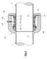
図1及び図2に示した、全体を符号Mで示した差込み式スリーブは、この場合、管1の端部区分1aに形成されている。差込み式スリーブは、開口110を備えた第1の端部100を有していて、差込み式スリーブMによって接続すべき管2の端部区分2aが、開口110から、差込み式スリーブに形成された当接肩部111に到るまで差込み式スリーブ内に導入される。端部100には、リング状の肩部121と周面122とを有した環状の溝120と、リング状の側方の画成面131と周面132とを有した環状の室130とが形成されている。溝120内には、エラストマ(又はその他の)材料から成るリングシール部材140の形態のクランプエレメントが挿入されていて、このリングシール部材140は、溝120の肩部121と周面122とに支持されている。室130内には、全体を符号150で示された実質的にスリーブ状の緊締エレメントが配置されていて、この緊締エレメントは、長手方向で室130の側方の画成面131からリングシール部材140まで延在している。リングシール部材140とスリーブ状の緊締エレメント150とは、差込み式スリーブ内に位置する管2の端部区分2aを取り囲んでいる。差込み式スリーブの端部100の外側には、流体の圧力媒体のための接続部160が配置されていて、この接続部は、孔161を介して室130へと開口している。接続部160を介して、例えば管路171経由で圧力媒体容器170から差込み式スリーブの室130へと流体の圧力媒体が供給される。圧力媒体容器ではなくて、適切な圧力媒体ポンプ若しくは圧縮機が設けられていてもよい。
The plug-in sleeve shown in FIG. 1 and FIG. 2 and generally indicated by the symbol M is formed in the end section 1 a of the
スリーブ状の緊締エレメント150の詳細な構成は、図3及び図4の斜視図により明らかである。緊締エレメント150は、第1の支持リング151と、この第1の支持リング151に軸方向で間隔を置いて位置する第2の支持リング152とを有している。両支持リング151と152との間には、複数の、例えば10対のプレート状のリンク153と154とが懸吊されていて、これらリンクは一緒に、緊締エレメント150の1つの周面を形成している。両支持リング151と152とプレート状のリンク153と154とは、1つの弾性的なシールホース155によって取り囲まれていて、このシールホース155は一方の側で半径方向外側に突出する固定フランジ155cを有している。シールホース155の内面には、リンク153と154を取り囲むポケット155aと155bとが設けられている。リンク153は、特に図5に示した概略的な断面図にも示されている。
The detailed configuration of the sleeve-
各対のプレート状のリンク153と154は長手方向で相並んで配置されていて、(限定的に)旋回可能に互いに枢着されている。各対のうち一方のリンク153は一方の支持リング151に、他方のリンク154は他方の支持リング152に(限定的に)旋回可能若しくは傾動可能に枢着されている。各対の両リンク153と154はそれぞれ互いに傾けられているので、緊締エレメント150の、リンク153と154により形成される周面は、両支持リング151と152の間の真ん中において、支持リングの近傍におけるよりも大きな直径を有している。即ち、緊締エレメント150は、周面の領域で若しくはリンク153と154の領域で、実質的に、樽状に膨らんだ、若しくは屈曲された形状を有していて、この形状を以下では初期形状と記載する。
Each pair of plate-
以下に、差込み式スリーブMの機能形式を説明する。 Below, the functional form of the insertion-type sleeve M is demonstrated.
差込み式スリーブMを管2の端部区分2aに固定するために、若しくは逆に端部区分2aを差込み式スリーブMに固定するために、管2の端部区分2aを、図1に示したように、開口110から差込み式スリーブMの端部100へと導入する。この時点では、リングシール部材140はまだ緊締されていない、若しくは圧縮されていないので、端部区分2aの導入は実際には力をかけずに行うことができる。
In order to fix the plug-in sleeve M to the
次いで、差込み式スリーブMにおける端部区分2aの固定が緊締エレメント150によって行われる。このために、緊締エレメント150の、リンク153と154により形成された周面の外面に流体の圧力媒体が負荷される。通常は圧縮空気であってよい圧力媒体をこのために、接続部160を介して室130へと導入する。緊締エレメント150を圧力負荷することにより、緊締エレメント150は半径方向内側に向かって変形し、リンク153と154との間の角度は、それぞれ対になったリンク153と154が1つの平面に位置するほど平らになる。周面のこのような内向きの変形により、両支持リング151と152は互いに離れるように押されるので、緊締エレメント150は長手方向で伸張する。これにより、緊締エレメント150の支持リング151は軸方向でリングシール部材140に対して押し付けられ、軸方向でリングシール部材140を圧縮する。リングシール部材のエラストマ材料は殆ど圧縮不能であるので、リングシール部材140は半径方向内側に向かって狭められ、この際に、管2の端部区分2aの外面を大きな力で押し、これにより端部区分は摩擦接続により保持される。
Next, the fastening of the
リンク153と154により形成される周面が、各対のリンク153と154が一平面に位置するほどまで内側に向かって変形した場合、緊締エレメント150は長手方向でその最も大きな伸長に達する。緊締エレメント150のこのように伸ばされた形状は、以下では死点形状と記載する。
When the peripheral surface formed by the
図1及び図2によりわかるように、リンク153と154とは、支持リングに枢着された領域で、管2の端部区分2a上方に、小さな半径方向の間隔を置いて位置している。これにより、緊締エレメント150の、リンク153と154により形成される周面が、リンク153と154とが管2の端部区分2aの外面に接するまで、死点形状を越えてさらに僅かに半径方向内側に向かって変形することができる。この場合、リンク153と154とは互いに小さい角度をなしている。リンク153と154のこの位置では、緊締エレメント150の形状は実質的に僅かにクッション形に湾曲若しくは屈曲している。緊締エレメントのこのような形状は、以下では終端形状と記載する。緊締エレメント150の終端形状は死点形状から僅かにしか逸れていないので、この終端形状における緊締エレメントの全長は、死点形状における全長よりも僅かにしか小さくない。この結果さらに、緊締エレメント150によりリングシール部材140に加えられる軸方向の押圧力は僅かにしか小さくならず、リングシール部材140から管2の端部区分2aに加えられる保持力はこれにより実際には殆ど損なわれない。図2には、差込み式スリーブが作動状態若しくは緊締状態で示されていて、緊締エレメント150は終端形状となっている。図4には、緊締エレメント150がこの終端形状で示されている。
As can be seen from FIGS. 1 and 2, the
リンク153と154の特別な構成及び配置により、緊締エレメント150にスナップ機能を与える一種のトグルレバーシステムが形成される。これは、圧力媒体により発生する内向き変形が、死点形状を越えるとすぐに、瞬発的に緊締エレメント150が終端形状へと変形することを意味する。終端形状は安定的であって、緊締エレメントは、この終端形状において外的な力を作用させずとも不動であるので、接続を維持するために、圧力媒体をさらに付与する必要はない。
Due to the special configuration and arrangement of the
特に図2によりわかるように、差込み式スリーブMには、緊締エレメントがどの状態にあるかを表示する表示部材が設けられている。表示部材はこの場合、ピン180として形成されていて、このピンは、緊締エレメント150のリンク153と154とによって形成される周面上に直立しており、半径方向外側に向かって開口161内へと延在している。緊締エレメント150の非作動状態(図1)では、ピン180は、外部から見えるほど開口161から突出している。緊締エレメント150の作動状態(図2)では、ピン180は、さらに内部に位置していて見えなくなっている。表示部材180の代わりに、例えば、図8に示したように、接続部160に封止部材162を設けることもでき、この封止部材162は、圧力媒体供給のためには除去され、破断される。
As can be seen in particular in FIG. 2, the plug-in sleeve M is provided with a display member for indicating in which state the tightening element is. The indicator member is in this case formed as a
さらに、差込み式スリーブMには、差込み式スリーブ内に管が導入されていない状態で、緊締エレメントが終端形状を越えて内方に向かって変形する可能性を阻止する安全手段を備えることができる。この手段は例えば、リンク153と154の相互の旋回若しくは傾動を制限する構成により得られる。
Furthermore, the plug-in sleeve M can be provided with safety means that prevent the clamping element from deforming inwardly beyond the terminal shape without a tube being introduced into the plug-in sleeve. . This means is obtained, for example, by a configuration that restricts the mutual turning or tilting of the
本発明による差込み式スリーブは、接続部160を介して差圧を付与することにより極めて簡単に再び解除することができる。この場合、緊締エレメント150が再び図1に示した初期状態となるまで、シールホース155に組み込まれているポケット155aと155bが、リンク153と154とを半径方向外側に向かって連行する。この場合、緊締エレメントが軸方向で短縮することにより、リングシール部材140からは再び負荷が除去され、管区分2aを実際には力をかけずに、差込み式スリーブMから引き出すことができる。
The plug-in sleeve according to the invention can be released again very simply by applying a differential pressure via the
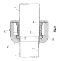
図6には、本発明による差込み式スリーブの実施の形態が示されている。この実施の形態では、差込み式スリーブMは独立部品として形成されていて、2つの管3と4とを接続している。
FIG. 6 shows an embodiment of a plug-in sleeve according to the invention. In this embodiment, the plug-in sleeve M is formed as an independent part and connects the two
この実施の形態による差込み式スリーブMは、図1及び図2に示した差込み式スリーブの端部100と同様に形成され構成された2つの端部100と200とを有している。両端部100と200は鏡像対照的に配置されていて、一体に形成されている。選択的には両端部は別個の部品として形成されていてよく、適当な形式で互いに接続されいてよい。両端部100と200は1つの共通の開口110を有していて、この開口に、互いに対向する側から、接続したい管3若しくは4のそれぞれ1つの端部区分3aと4aとが導入される。差込み式スリーブの端部100と200は、図1及び図2に示した端部100と同様に形成され、構成されているので、機能が同じ部分には、図1及び図2と同じ符号を付与している。
The plug-in sleeve M according to this embodiment has two
圧力媒体の供給は、この実施の形態では、各端部100と200にそれぞれ配置された2つの別個の接続部160を介して行われる。しかしながら両端部の室130を連通するように接続することもでき、この場合、圧力媒体の供給は1つの共通の接続部で十分である。
In this embodiment, the supply of the pressure medium is performed via two
図7の実施の形態では、差込み式スリーブは同様に、独立部品として形成されていて、この場合、ケーブルスリーブを形成している。差込み式スリーブの端部100は、貫通開口110を有していて、この開口110からケーブル5が導入される。その他の点では、差込み式スリーブは、図1及び図2の実施の形態と同様に形成され、構成されているので、機能が同じ部分には、図1及び図2と同じ符号を付与している。
In the embodiment of FIG. 7, the plug-in sleeve is likewise formed as an independent part, in this case forming a cable sleeve. The
シール効果及び緊締力(引き抜き強度)を増強するために、差込み式スリーブの端部ごとに、直列配置のような形式で、それぞれ対応する緊締エレメントを備えた2つ以上のリングシール部材を設けることもできる。管表面を相応に構成することにより、接続を形状接続的に形成することもできる。摩擦力を高める手段(例えば砂)をリングシール部材の接触区域に導入することにより、保持力をさらに強化することができる。リングシール部材140は通常、エラストマ材料から成っているが、特別な使用例のためには、硬質ゴム、金属、又はエラストマプラスチックとは異なる材料から成っていてもよい。リングシール部材は中空に形成されてもよい。シールリングは、(保持すべき対象物若しくは管に関して)特別に高い静止摩擦係数を有した材料から製造されてもよく、この場合、この特性は、シールリングを製造する際に、特別な物質(例えば、砂)を出発材料に加えることにより得ることができる。
To enhance the sealing effect and tightening force (pullout strength), each end of the plug-in sleeve should be provided with two or more ring seal members, each with a corresponding tightening element, in the form of a series arrangement. You can also. By configuring the tube surface accordingly, the connection can also be formed like a shape connection. By introducing means for increasing the frictional force (for example, sand) into the contact area of the ring seal member, the holding force can be further strengthened. The
シール効果の改善若しくは引き抜き力の向上は、クランプ位置の領域におけるクランプすべき対象物若しくは管の摩擦を高める表面構造によっても得られ、例えば、溝を設けることによって、又は砂等を添加することによって得られる。 The improvement of the sealing effect or the pull-out force can also be obtained by a surface structure which increases the friction of the object to be clamped or the tube in the region of the clamping position, for example by providing grooves or by adding sand etc. can get.
上述した実施の形態では、緊締エレメント150はプレート状のリンク153と154を備えている。しかしながら、圧力媒体の外部からの負荷に基づく緊締エレメントの内向き変形により、緊締エレメントの軸方向の伸長が達成され、かつ、緊締エレメントが、必要な緊締力をリングシール部材に伝達するのに十分剛性的に形成されていることが保証されているならば、緊締エレメントの別の構成形式も可能であることは言うまでもない。特に、緊締エレメントは、例えば適切なプラスチック又は金属から一体に形成されてもよい。
In the above-described embodiment, the tightening
上記説明からわかるように、管の固定及びシールは、軸方向に圧縮されたゴム弾性的なエレメント(リングシール部材)により行われる。過圧下にある液体又は気体の媒体による面(緊締エレメントの周面)への力作用により、管軸線に対して半径方向内側に向かって作用する一次力が形成される。(緊締エレメントのリンクにより形成される)機械的な変換エレメントが、この力をさらに変換し、強化し、管軸線に対して平行な方向で、クランプ・シールエレメント(リングシール部材)へと導入する。保持及びシール機能は、同じゴム弾性的なエレメントにより発揮される。 As can be seen from the above description, fixing and sealing of the tube are performed by a rubber elastic element (ring seal member) compressed in the axial direction. Due to the force action on the surface (surrounding surface of the tightening element) by the liquid or gas medium under overpressure, a primary force acting radially inward with respect to the tube axis is formed. A mechanical transducer element (formed by the link of the clamping elements) further transforms and strengthens this force and introduces it into the clamping and sealing element (ring seal member) in a direction parallel to the tube axis. . The holding and sealing functions are exerted by the same rubber elastic element.
管状の緊締エレメント(円形又は多角形)は、管軸線に対して平行に向けられた個別の複数のリンクから成っていて、これらのリンクは、半径方向外側から作用する力が加えられた際に、軸方向に伸長することができ、この場合、力作用を発揮することができるように形成されている。これらのリンクは、半径方向外側から作用する力を変換する際に、軸方向へ向けられた力への強力な変換が行われるように設計されている。 A tubular clamping element (circular or polygonal) consists of a plurality of individual links oriented parallel to the tube axis, when these forces are applied from the outside in the radial direction. It is possible to extend in the axial direction, and in this case, it is formed so as to exert a force action. These links are designed in such a way that a strong conversion to axially directed forces takes place when converting forces acting from outside in the radial direction.
これらのリンクは、所定の直線的な伸長が超過されると、これらのエレメントがその長さを(殆ど完全に)維持し(スナップ機能)、圧力媒体により加えられる外部から作用する力がなくなっても、戻ることはないように、設計されている。 These links, when a predetermined linear extension is exceeded, these elements maintain their length (almost completely) (snap function) and there is no external force applied by the pressure medium. But it is designed not to return.
管は力をかけることなく、接合させることができる。機械的な接続工程は、外的な反応力やトルクを発生させることはない。接続は、最低限の準備(切断や、場合によっては切断縁のクリーニング)しか必要としない。接続工程が行われたあと、冷却時間や硬化時間を要さない。接続のために迅速に負荷され、その後の作業をすぐに行うことができる。 The tubes can be joined without applying force. The mechanical connection process does not generate an external reaction force or torque. The connection requires minimal preparation (cutting and possibly cutting edge cleaning). No cooling or curing time is required after the connection process has been performed. Loaded quickly for connection and subsequent work can be done immediately.
緊締されたプラスチック管への大きな面圧により、管は部分的にくびれ、これにより、いわば形状接続が形成される。このようなくびれが不都合なものであったり、大きすぎる場合には、図9の実施の形態に示したように、管内壁を支持スリーブ175によって補強することができる。 この場合、支持スリーブ175の外周面に、例えば溝によって摩擦を高めるような構造化を施すように構成することができる。クランプ力の作用下で、壁の薄い管は、支持スリーブの表面構造に適合し、ひいては、引き抜き力を高める効果を発揮する。その他の点では、図9の差込み式スリーブは、図1及び図2の実施の形態と同様に形成され、構成されているので、機能が同じ部分には、図1及び図2と同じ符号を付与している。
Due to the high surface pressure on the clamped plastic tube, the tube is partially constricted, which forms a so-called shape connection. If the necking is inconvenient or too large, the inner wall of the tube can be reinforced by the
図10〜図13には、本発明による差込み式スリーブの変化実施例が示されている。この場合、引き抜き力をさらに高めるために、クランプエレメント150とリングシール部材140との間に、クランプ確保板185が配置されている。クランプ確保板185は、図13に(縮小化されて)平面図で示されている。その他の点では、図10〜図12の差込み式スリーブは、図1及び図2の実施の形態と同様に形成され、構成されているので、機能が同じ部分には、図1及び図2と同じ符号を付与している。
10 to 13 show a variant embodiment of the plug-in sleeve according to the invention. In this case, a
クランプ確保板185は、公知の形式で、内側に向けられ、ワッシャ平面から外に向かって曲げられた歯若しくは爪185aを有していて、これらの歯若しくは爪185aは、緊締エレメント150の非作動状態では管区分2aの表面に接触しない、又は極めて僅かにしか接触しない(図10)。緊締エレメント150が緊締されると(図11)、クランプ確保板185は変形し、その歯若しくは爪185aが、図12に詳しく示したように、管区分2aの表面に食い込む。これにより引き抜き強度は高まる。スペーサリングによって分離された複数のクランプ確保板を設けることもできる。
The
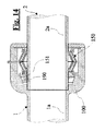
図14〜図17に示した本発明による差込み式スリーブの実施の形態では、リングシール部材の代わりに、クランプエレメントとしてリングエレメント190が設けられている。その他の点では、図14〜図17の差込み式スリーブは、図1及び図2の実施の形態と同様に形成され、構成されているので、機能が同じ部分には、図1及び図2と同じ符号を付与している。
In the embodiment of the plug-in sleeve according to the present invention shown in FIGS. 14 to 17, a
リングエレメント190は、円錐状の外面191を有していて、この外面191は、緊締エレメント150から離れる方向で先細りしている。差込み式スリーブの端部100には、リングエレメント190の円錐面191と協働する、同様の対応面192が設けられている。(軸方向で実質的に圧縮不能な)リングエレメント190が、緊締エレメント150の第1の支持リング151に接触している。緊締エレメント150の非作動状態では、リングエレメント190の内径は、保持したい管2の端部区分2aの外径よりも僅かに大きい(図14及び図16の詳細図)。緊締エレメント150の作動状態では、リングエレメント190は、緊締エレメント150の長さが変化することにより軸方向に摺動し、この際、リングエレメント190の円錐状の外面191は対応面192に沿って滑動し、この場合、リングエレメント190は半径方向に押しつぶされる。これにより、リングエレメント190は管2の端部区分2aの外面に密に押し付けられ、これにより管をしっかりとクランプする(図15及び図17の詳細図)。リングエレメントは場合によっては、(例えば、ドリルチャックの形式で)セグメント化されて形成されていてもよい。
The
最後に、図18〜図21に本発明による差込み式スリーブのさらに別の実施の形態を示している。この差込み式スリーブは、図1及び図2に示した実施の形態と図14〜図17に示した実施の形態の組み合わせである。この実施の形態では、クランプエレメントとして、リングシール部材140もリングエレメント190も設けられている。その他の点では、図18〜図21の差込み式スリーブは、図1及び図2の実施の形態と同様に形成され、構成されているので、機能が同じ部分には、図1及び図2と同じ符号を付与する。この変化実施例では、特に図20及び図21に詳しく示されているように、緊締エレメント150がリングエレメント190を押し、これによりリングエレメント190がリングシール部材140を圧縮する。
Finally, FIG. 18 to FIG. 21 show still another embodiment of the plug-in sleeve according to the present invention. This plug-in sleeve is a combination of the embodiment shown in FIGS. 1 and 2 and the embodiment shown in FIGS. In this embodiment, both the
勿論、図6及び図7に示した実施の形態も、図9〜図21に示した実施の形態と対応するように形成することもできる。 Of course, the embodiment shown in FIGS. 6 and 7 can also be formed to correspond to the embodiment shown in FIGS.
本発明による差込み式スリーブは特に、管接続部材の製造に適している。しかしながら本発明は、例えばケーブル接続等に使用することもできる。差込み式スリーブは、横断面が円形の接続部品に限定されるものではない。さらに、差込み式スリーブは、カバー又は閉鎖キャップとして使用することもできる。 The plug-in sleeve according to the invention is particularly suitable for the manufacture of pipe connection members. However, the present invention can also be used for cable connection, for example. The plug-in sleeve is not limited to connecting parts having a circular cross section. Furthermore, the plug-in sleeve can also be used as a cover or a closure cap.
Claims (14)
押圧力を受けて前記クランプエレメント(140;190)に前記差込み式スリーブの長手方向で連結可能な、前記クランプエレメント(140;190)に軸方向力を負荷する実質的にスリーブ状の緊締エレメント(150)が設けられており、前記クランプエレメント(140;190)は、前記軸方向力が負荷される際に、半径方向で狭まるように成形されかつ構成されており、前記緊締エレメント(150)は、流体の圧力媒体による外的な負荷により前記緊締エレメント(150)が軸方向で伸長させられ、これにより前記クランプエレメント(140;190)に前記軸方向力が負荷されるように構成されかつ配置されており、
前記緊締エレメント(150)が、第1の支持リング(151)と、該第1の支持リングに対して間隔を置いて配置された第2の支持リング(152)と、前記両支持リング(151,152)の間に配置された複数対のプレート状のリンク(153,154)とを有しており、1つの対のうちの前記リンク(153,154)がそれぞれ、長手方向で相並んで配置されていて、互いに旋回可能に枢着されており、1つの対のうちそれぞれ一方のリンク(153)が前記第1の支持リング(151)に、1つの対のうちそれぞれ他方のリンク(154)が前記第2の支持リング(152)に、傾動可能に枢着されており、1つの対のうちの両リンク(153,154)がそれぞれ互いに傾けられて配置されていることを特徴とする、差込み式スリーブ。 Rod-like, cable-like, or a bayonet sleeve for securing to the object a tubular, the outer surface of a segment (2a) said section and the opening (110) for accommodating the object (2a) In a plug-in sleeve with a first end (100) having an abutable clamping element (140; 190),
A substantially sleeve-like clamping element (loading axial force on the clamping element (140; 190), which is capable of being connected to the clamping element (140; 190) in the longitudinal direction of the plug-in sleeve under pressure. 150), and the clamping element (140; 190) is shaped and configured to radially narrow when the axial force is applied, the clamping element (150) The clamping element (150) is configured to be axially extended by an external load by a fluid pressure medium, whereby the axial force is applied to the clamping element (140; 190). Has been
The tightening element (150) includes a first support ring (151), a second support ring (152) spaced from the first support ring, and both the support rings (151). , 152), and a plurality of pairs of plate-like links (153, 154) arranged between the links (153, 154) in one pair. Arranged so as to be pivotable with respect to each other, and one link (153) in one pair is connected to the first support ring (151), and the other link (154) in one pair. ) Is pivotably attached to the second support ring (152), and both links (153, 154) of one pair are arranged to be inclined with respect to each other. , Plug-in type Reeve.
Applications Claiming Priority (3)
| Application Number | Priority Date | Filing Date | Title |
|---|---|---|---|
| CH428/14 | 2014-03-20 | ||
| CH00428/14A CH709441A2 (en) | 2014-03-20 | 2014-03-20 | Push-fit socket. |
| PCT/CH2015/000038 WO2015139148A1 (en) | 2014-03-20 | 2015-03-09 | Plug-type sleeve |
Publications (2)
| Publication Number | Publication Date |
|---|---|
| JP2017516043A JP2017516043A (en) | 2017-06-15 |
| JP6602835B2 true JP6602835B2 (en) | 2019-11-06 |
Family
ID=52705908
Family Applications (1)
| Application Number | Title | Priority Date | Filing Date |
|---|---|---|---|
| JP2017500105A Active JP6602835B2 (en) | 2014-03-20 | 2015-03-09 | Plug-in sleeve |
Country Status (11)
| Country | Link |
|---|---|
| US (1) | US10119639B2 (en) |
| EP (1) | EP3120064B1 (en) |
| JP (1) | JP6602835B2 (en) |
| KR (1) | KR102327034B1 (en) |
| CA (1) | CA2941922C (en) |
| CH (1) | CH709441A2 (en) |
| ES (1) | ES2701507T3 (en) |
| PL (1) | PL3120064T3 (en) |
| PT (1) | PT3120064T (en) |
| RU (1) | RU2675959C2 (en) |
| WO (1) | WO2015139148A1 (en) |
Families Citing this family (6)
| Publication number | Priority date | Publication date | Assignee | Title |
|---|---|---|---|---|
| GB2573103B (en) * | 2018-04-20 | 2020-10-07 | Cejn Ab | Connector with pressure actuated elastic clamp |
| DE102019116326A1 (en) * | 2019-06-14 | 2020-12-17 | Theodor WÜST | Pipe joint applicator and method of making a joint |
| DE102019127857A1 (en) * | 2019-10-16 | 2021-04-22 | Voss Automotive Gmbh | Tooth lock washer |
| CH718244A1 (en) | 2021-01-06 | 2022-07-15 | Swiss Tech Innovation AG | Sealing assembly and connecting sleeve. |
| US20230392729A1 (en) * | 2022-06-01 | 2023-12-07 | Polyflow, Llc | End Fitting for a Pipe and Associated Methods |
| CN118157070B (en) * | 2024-05-10 | 2024-07-19 | 国网山东省电力公司聊城市茌平区供电公司 | Cable end sealing structure |
Family Cites Families (26)
| Publication number | Priority date | Publication date | Assignee | Title |
|---|---|---|---|---|
| US1930361A (en) * | 1930-03-20 | 1933-10-10 | Collins Kilmer Corp | Contractible and expansible well packer |
| US2291143A (en) * | 1939-03-20 | 1942-07-28 | Cicero C Brown | Bradenhead |
| GB556256A (en) * | 1942-03-17 | 1943-09-27 | Raymond James Mitchell | Improvements in methods and apparatus for the application and utilization of fluid pressure |
| US2826420A (en) * | 1954-01-08 | 1958-03-11 | Karl A Klingler | Hydraulic holding means for chucks and the like |
| US3097866A (en) * | 1960-11-14 | 1963-07-16 | Weatherhead Co | Pressurized hose end |
| US3271053A (en) * | 1964-07-02 | 1966-09-06 | Kurachi Hisaharu | Means for coupling a hose to a pipe |
| GB1271855A (en) * | 1968-11-22 | 1972-04-26 | Petroles Cie Francaise | Improvements relating to elements for coupling pipes |
| US3737139A (en) * | 1971-06-28 | 1973-06-05 | Hydril Co | Annular blowout preventer |
| US3810665A (en) * | 1971-11-17 | 1974-05-14 | F Rodgers | Pipe coupling |
| FR2166593A5 (en) * | 1971-12-30 | 1973-08-17 | Pont A Mousson | |
| JPS4955414U (en) * | 1972-08-22 | 1974-05-16 | ||
| US3843167A (en) * | 1973-01-31 | 1974-10-22 | B Gronstedt | Hydraulically actuated pipe coupling |
| DE2426234C2 (en) * | 1974-05-29 | 1985-04-04 | Allstar Verbrauchsgüter GmbH & Co KG, 6000 Frankfurt | Connector made of plastic or metal for the detachable connection of pipes with different diameters |
| US4195865A (en) * | 1976-11-03 | 1980-04-01 | Martin Charles F | Apparatus for connecting tubular members |
| US4371198A (en) * | 1976-11-03 | 1983-02-01 | Martin Charles F | Apparatus for connecting tubular members |
| US4150250A (en) * | 1977-07-01 | 1979-04-17 | General Signal Corporation | Strain relief fitting |
| US4178020A (en) * | 1977-12-15 | 1979-12-11 | Big-Inch Marine Systems, Inc. | Locking slip joint and method of use |
| US4431215A (en) * | 1981-04-20 | 1984-02-14 | Exxon Production Research Co. | Riser connector |
| US4676531A (en) * | 1985-04-15 | 1987-06-30 | Martin Charles F | Apparatus for clamping and sealing the outer surface of a pipe and fittings for pipe connection |
| JPH0241435Y2 (en) * | 1985-05-08 | 1990-11-05 | ||
| GB9515473D0 (en) * | 1995-07-28 | 1995-09-27 | Guest John D | Improvements in or relating to tube couplings |
| NL1011520C2 (en) * | 1999-03-10 | 2000-09-12 | Wijnant Van Genderen | Pressure device for fixing or sealing bodies. |
| JP3921208B2 (en) * | 2003-06-02 | 2007-05-30 | 乙一 落合 | Tube connection structure |
| KR20080000142U (en) * | 2008-01-14 | 2008-02-04 | 남정운 | Stainless pipe piping material |
| US9068423B2 (en) * | 2012-02-03 | 2015-06-30 | National Oilwell Varco, L.P. | Wellhead connector and method of using same |
| US9074450B2 (en) * | 2012-02-03 | 2015-07-07 | National Oilwell Varco, L.P. | Blowout preventer and method of using same |
-
2014
- 2014-03-20 CH CH00428/14A patent/CH709441A2/en not_active Application Discontinuation
-
2015
- 2015-03-09 PL PL15711418T patent/PL3120064T3/en unknown
- 2015-03-09 RU RU2016141090A patent/RU2675959C2/en active
- 2015-03-09 JP JP2017500105A patent/JP6602835B2/en active Active
- 2015-03-09 PT PT15711418T patent/PT3120064T/en unknown
- 2015-03-09 WO PCT/CH2015/000038 patent/WO2015139148A1/en active Application Filing
- 2015-03-09 ES ES15711418T patent/ES2701507T3/en active Active
- 2015-03-09 EP EP15711418.2A patent/EP3120064B1/en active Active
- 2015-03-09 KR KR1020167028605A patent/KR102327034B1/en active IP Right Grant
- 2015-03-09 CA CA2941922A patent/CA2941922C/en active Active
-
2016
- 2016-09-20 US US15/270,653 patent/US10119639B2/en active Active
Also Published As
| Publication number | Publication date |
|---|---|
| EP3120064A1 (en) | 2017-01-25 |
| CH709441A2 (en) | 2015-09-30 |
| CA2941922A1 (en) | 2015-09-24 |
| KR20160134764A (en) | 2016-11-23 |
| RU2016141090A3 (en) | 2018-10-18 |
| ES2701507T3 (en) | 2019-02-22 |
| RU2675959C2 (en) | 2018-12-25 |
| US20170009917A1 (en) | 2017-01-12 |
| WO2015139148A1 (en) | 2015-09-24 |
| JP2017516043A (en) | 2017-06-15 |
| RU2016141090A (en) | 2018-04-28 |
| EP3120064B1 (en) | 2018-09-12 |
| CA2941922C (en) | 2019-12-31 |
| KR102327034B1 (en) | 2021-11-16 |
| PL3120064T3 (en) | 2019-02-28 |
| US10119639B2 (en) | 2018-11-06 |
| PT3120064T (en) | 2018-12-19 |
Similar Documents
| Publication | Publication Date | Title |
|---|---|---|
| JP6602835B2 (en) | Plug-in sleeve | |
| US4358079A (en) | Moisture resistant clamp for portable cables | |
| EP3540284A1 (en) | Tension-resistant coupling piece | |
| US5600094A (en) | Fixing device to anchor and seal an elongate member | |
| US4103941A (en) | Disconnectable coupling for conduits of deformable material | |
| HUP0303824A2 (en) | Pipe coupling | |
| JPH04229011A (en) | Electric connector | |
| KR20040044468A (en) | Support sleeve for use in a tube coupling and a coupling housing for use together with said sleeve | |
| JP2010223422A (en) | Pressing wheel assembly for connecting pipes | |
| US7699357B2 (en) | Coupling for tubes | |
| NO313720B1 (en) | Connection for connecting a rudder or hose when pushed in | |
| US3332708A (en) | Tube coupling having deformable gripping and sealing means | |
| JP6910662B2 (en) | Assembly of flexible tube and joint body and its method | |
| US4238132A (en) | Connector | |
| KR102443762B1 (en) | pipe connection forming device | |
| JP2008528890A (en) | Device for liquid-tight connection of soft tubes | |
| CN110657307A (en) | Anti-slip ring, connecting assembly, anti-slip assembly and connecting pipe fitting | |
| KR101918082B1 (en) | Low Pressure Compression Type Pipe Fitting And Method of Compressing Thereof | |
| CS195274B2 (en) | Dismountable adapter connection for the pipeline | |
| KR101469151B1 (en) | One-pushing pipe jointer | |
| JP2014003128A (en) | Cable clamp device of explosion-proof type cable ground | |
| DE502007002335D1 (en) | Cable gland | |
| US20240151334A1 (en) | Seal assembly and joint bushing | |
| KR102426743B1 (en) | Connecting Structure of Pipe | |
| US20180224035A1 (en) | Connecting Arrangement and Press Ring for A Connecting Arrangement |
Legal Events
| Date | Code | Title | Description |
|---|---|---|---|
| A521 | Request for written amendment filed |
Free format text: JAPANESE INTERMEDIATE CODE: A523 Effective date: 20160926 |
|
| A621 | Written request for application examination |
Free format text: JAPANESE INTERMEDIATE CODE: A621 Effective date: 20171207 |
|
| A977 | Report on retrieval |
Free format text: JAPANESE INTERMEDIATE CODE: A971007 Effective date: 20181108 |
|
| A131 | Notification of reasons for refusal |
Free format text: JAPANESE INTERMEDIATE CODE: A131 Effective date: 20190107 |
|
| A521 | Request for written amendment filed |
Free format text: JAPANESE INTERMEDIATE CODE: A523 Effective date: 20190402 |
|
| TRDD | Decision of grant or rejection written | ||
| A01 | Written decision to grant a patent or to grant a registration (utility model) |
Free format text: JAPANESE INTERMEDIATE CODE: A01 Effective date: 20190910 |
|
| A61 | First payment of annual fees (during grant procedure) |
Free format text: JAPANESE INTERMEDIATE CODE: A61 Effective date: 20191009 |
|
| R150 | Certificate of patent or registration of utility model |
Ref document number: 6602835 Country of ref document: JP Free format text: JAPANESE INTERMEDIATE CODE: R150 |
|
| S111 | Request for change of ownership or part of ownership |
Free format text: JAPANESE INTERMEDIATE CODE: R313113 |
|
| R350 | Written notification of registration of transfer |
Free format text: JAPANESE INTERMEDIATE CODE: R350 |
|
| R250 | Receipt of annual fees |
Free format text: JAPANESE INTERMEDIATE CODE: R250 |
|
| R250 | Receipt of annual fees |
Free format text: JAPANESE INTERMEDIATE CODE: R250 |