JP6602467B2 - Laminated iron core and manufacturing method thereof - Google Patents
Laminated iron core and manufacturing method thereof Download PDFInfo
- Publication number
- JP6602467B2 JP6602467B2 JP2018510569A JP2018510569A JP6602467B2 JP 6602467 B2 JP6602467 B2 JP 6602467B2 JP 2018510569 A JP2018510569 A JP 2018510569A JP 2018510569 A JP2018510569 A JP 2018510569A JP 6602467 B2 JP6602467 B2 JP 6602467B2
- Authority
- JP
- Japan
- Prior art keywords
- laminated
- core
- concave portion
- cores
- iron core
- Prior art date
- Legal status (The legal status is an assumption and is not a legal conclusion. Google has not performed a legal analysis and makes no representation as to the accuracy of the status listed.)
- Active
Links
Images


Classifications
-
- H—ELECTRICITY
- H02—GENERATION; CONVERSION OR DISTRIBUTION OF ELECTRIC POWER
- H02K—DYNAMO-ELECTRIC MACHINES
- H02K1/00—Details of the magnetic circuit
- H02K1/06—Details of the magnetic circuit characterised by the shape, form or construction
- H02K1/12—Stationary parts of the magnetic circuit
- H02K1/18—Means for mounting or fastening magnetic stationary parts on to, or to, the stator structures
-
- H—ELECTRICITY
- H02—GENERATION; CONVERSION OR DISTRIBUTION OF ELECTRIC POWER
- H02K—DYNAMO-ELECTRIC MACHINES
- H02K15/00—Methods or apparatus specially adapted for manufacturing, assembling, maintaining or repairing of dynamo-electric machines
- H02K15/02—Methods or apparatus specially adapted for manufacturing, assembling, maintaining or repairing of dynamo-electric machines of stator or rotor bodies
Description
この発明は、電動機や変成器等の鉄心構造に関し、板状のコア片が積層された複数の積層コアを環状に連結する積層型鉄心およびその製造方法に関するものである。 The present invention relates to an iron core structure such as an electric motor or a transformer, and more particularly to a laminated iron core in which a plurality of laminated cores in which plate-like core pieces are laminated are connected in a ring shape and a method for manufacturing the same.
従来、電動機の固定子として、プレス打抜きされたシート状のコア片を積層した積層コアが鉄心装置として使用されている。各ティースが薄肉部を介して直線状に繋がる形状のコア片からなる積層コアを金型で一度に形成し、積層コアを一体として巻線可能とし、その端部同士を円環状に折り曲げることで鉄心装置が得られる構成が開示されている(例えば、特許文献1参照)。
また、積層コア端部に形成された凸部と、反対端部の凹部を位置合わせして積巾方向に挿入することで、鉄心装置が得られる構成が開示されている(例えば、特許文献2参照)。Conventionally, as a stator of an electric motor, a laminated core obtained by laminating press-cut sheet-like core pieces has been used as an iron core device. By forming a laminated core consisting of core pieces in a shape where each tooth is connected in a straight line through a thin part with a mold, the laminated core can be wound as a unit, and its ends are bent into an annular shape. The structure which can obtain an iron core device is indicated (for example, refer to patent documents 1).
Moreover, the structure which obtains an iron core apparatus by aligning the convex part formed in the laminated | stacked core edge part and the recessed part of an opposite edge part, and inserting in a product width direction is disclosed (for example, patent document 2). reference).
しかし、特許文献1開示発明では、積層コアの生産性が良く、巻線と搬送は容易であるが、金型およびプレス装置が大型化するため、大きな投資が必要となり、生産台数が少ない機種には適用が難しかった。又、特許文献2開示発明では、積層コアを凸部と凹部を位置合わせして積巾方向に挿入するため、挿入時にカジリが発生し、端部まで挿入できない懸念がある。
However, in the invention disclosed in
この発明は、上記の問題を解決するためになされたものであり、積層コアを容易に連結でき、金型を小型化できる積層型鉄心およびその製造方法を提供することを目的とする。 The present invention has been made to solve the above-described problems, and an object of the present invention is to provide a laminated iron core that can easily connect laminated cores and that can reduce the size of a mold, and a method for manufacturing the same.
この発明に係る積層型鉄心は、同一形状の板状コア片を積層固定した積層コアを複数連結して環状と成す積層型鉄心であって、積層コアの一方の端部に凸部を有し、積層コアの他方の端部に凹部を有し、凹部の外周側の一部に切り欠きを有し、凹部は、凸部を囲む穴部を形成するようにC字型に変形可能な構造を持ち、切り欠きを有する凹部の外周側の一部は薄肉部であり、切り欠きは、積層コア同士をスライド可能とする逃がし溝を有し、凹部は2段階の変形が可能な構造であり、凹部がU字型となることで、積層コア同士を周方向にスライド可能な状態で連結させる第1段階の変形と、凹部が前記C字型となることで、積層コア同士が動かない状態で固定する第2段階の変形を有し、積層コア同士が外れることなく、積層コアのティース部同士を離れる方向にスライドさせることができるものである。
また、この発明に係る積層型鉄心は、同一形状の板状コア片を積層固定した積層コアを複数連結して環状と成す積層型鉄心であって、積層コアの一方の端部に凸部を有し、積層コアの他方の端部に凹部を有し、凹部の外周側の一部に切り欠きを有し、凹部は、凸部を囲む穴部を形成するようにC字型に変形可能な構造を持ち、切り欠きを有する凹部の外周側の一部は薄肉部であり、切り欠きは、積層コア同士をスライド可能とする逃がし溝を有し、凹部の外周側の先端部と接する位置に、凸部の外周側に径方向に伸びる突起部を有する構造を有し、凹部がC字型に変形後にスプリングバックによって変形が戻ることを防止するものである。
また、この発明に係る積層型鉄心は、同一形状の板状コア片を積層固定した積層コアを複数連結して環状と成す積層型鉄心であって、積層コアの一方の端部に凸部を有し、積層コアの他方の端部に凹部を有し、凹部の外周側の一部に切り欠きを有し、凹部は、凸部を囲む穴部を形成するようにC字型に変形可能な構造を持ち、凹部は2段階の変形が可能な構造であり、凹部がU字型となることで、積層コア同士を周方向にスライド可能な状態で連結させ、積層コア同士が外れることなく、積層コアのティース部同士を離れる方向にスライドさせることができる第1段階の変形と、凹部が前記C字型となることで、積層コア同士が動かない状態で固定する第2段階の変形を有するものである。
また、この発明に係る積層型鉄心は、同一形状の板状コア片を積層固定した積層コアを複数連結して環状と成す積層型鉄心であって、積層コアの一方の端部に凸部を有し、積層コアの他方の端部に凹部を有し、凹部の外周側の一部に切り欠きを有し、凹部は、凸部を囲む穴部を形成するようにC字型に変形可能な構造を持ち、凹部の外周側の先端部と接する位置に、凸部の外周側に径方向に伸びる突起部を有する構造を有し、凹部がC字型に変形後にスプリングバックによって変形が戻ることを防止するものである。
また、この発明に係る積層型鉄心は、同一形状の板状コア片を積層固定した積層コアを複数連結して環状と成す積層型鉄心であって、積層コアの一方の端部に凸部を有し、積層コアの他方の端部に凹部を有し、凹部の外周側の一部に切り欠きを有し、凹部は、凸部を囲む穴部を形成するようにC字型に変形可能な構造を持ち、凹部を構成する外径側の突起において、突起の内径基部側に張り出しを設け、内径先端側に谷部を設ける構造とし、一方凸部の基部の外径側に張り出しを有する構造とし、積層コア同士を直線状態に並べた時に、凹部の張り出しと凸部の張り出しが接触し、積層コア同士が外れることなく、積層コアのティース部同士を離れる方向にスライドさせることができ、積層コア同士を円環状態に並べた時に、凹部の谷部と凸部の張り出しが嵌合する構造を有するものである。
A laminated iron core according to the present invention is a laminated iron core that is formed by connecting a plurality of laminated cores in which plate-shaped core pieces having the same shape are laminated and fixed, and has a convex portion at one end of the laminated core. A structure having a recess at the other end of the laminated core, a notch in a part on the outer peripheral side of the recess, and the recess being deformable into a C shape so as to form a hole surrounding the protrusion the have a thin portion part of the outer peripheral side of the recess having a notch, notch, the laminated cores have a relief groove and slidable recess is in capable variant of two-stage construction The first stage of deformation that connects the laminated cores in a slidable state in the circumferential direction due to the U-shaped recess and the state where the stacked cores do not move due to the C-shaped recess. The core of the laminated core has a second stage deformation that is fixed at Those that can be slid away to each other.
The laminated core according to the present invention is a laminated iron core that is formed by connecting a plurality of laminated cores in which plate-shaped core pieces having the same shape are laminated and fixed, and has a convex portion at one end of the laminated core. Has a recess at the other end of the laminated core, has a notch on a part of the outer periphery of the recess, and the recess can be deformed into a C shape to form a hole surrounding the protrusion A part of the outer peripheral side of the recess having a notch is a thin part, and the notch has an escape groove that allows the laminated cores to slide with each other and is in contact with the outer end of the recess Further, it has a structure having a projecting portion extending in the radial direction on the outer peripheral side of the convex portion, and prevents the concave portion from returning to the deformation by the springback after the concave portion is deformed into a C shape.
The laminated core according to the present invention is a laminated iron core that is formed by connecting a plurality of laminated cores in which plate-shaped core pieces having the same shape are laminated and fixed, and has a convex portion at one end of the laminated core. Has a recess at the other end of the laminated core, has a notch on a part of the outer periphery of the recess, and the recess can be deformed into a C shape to form a hole surrounding the protrusion The concave part is a structure that can be deformed in two steps, and the concave part is U-shaped, so that the laminated cores can be connected in a slidable state in the circumferential direction without causing the laminated cores to come off. , a first stage of deformation is Ru can be slid in a direction away tooth portions of the laminated core, that the recess is the C-shape, deformation of the second stage of fixed while the laminated cores from moving It is what has.
The laminated core according to the present invention is a laminated iron core that is formed by connecting a plurality of laminated cores in which plate-shaped core pieces having the same shape are laminated and fixed, and has a convex portion at one end of the laminated core. Has a recess at the other end of the laminated core, has a notch on a part of the outer periphery of the recess, and the recess can be deformed into a C shape to form a hole surrounding the protrusion It has a structure that has a projecting portion extending radially on the outer peripheral side of the convex portion at a position in contact with the outer peripheral end portion of the concave portion, and the deformation is restored by the springback after the concave portion is deformed into a C shape. This is to prevent this.
The laminated core according to the present invention is a laminated iron core that is formed by connecting a plurality of laminated cores in which plate-shaped core pieces having the same shape are laminated and fixed, and has a convex portion at one end of the laminated core. Has a recess at the other end of the laminated core, has a notch on a part of the outer periphery of the recess, and the recess can be deformed into a C shape to form a hole surrounding the protrusion The protrusion on the outer diameter side constituting the recess has a structure in which a protrusion is provided on the inner diameter base side of the protrusion and a valley is provided on the tip end side of the inner diameter, while a protrusion is provided on the outer diameter side of the base of the protrusion. the structure, when arranging the laminated cores in a linear state, overhanging Zhang Ri out and the convex portion of the concave portion are in contact, the laminated core without departing each other, be slid in a direction away tooth portions of the laminated core can, when arranged laminated cores in an annular state, the recess of the valley and the convex Zhang Ri out has the structure to be fitted in.
この発明に係る積層型鉄心の製造方法は、複数の積層コアを連結して環状となす積層型鉄心の製造方法であって、積層コアの一方の端部に凸部を有し、積層コアの他方の端部に凹部を有し、凹部の外周側の一部に切り欠きを有し、凹部は凸部を囲む穴部を形成するようにC字型に変形可能な積層コアを用い、第1の積層コアの凸部を第2の積層コアの凹部に挿入する位置合わせ工程と、凹部をU字型に変形させて第1の積層コアの凸部を囲む穴部を形成し、積層コア同士が外れることを防止し、積層コア同士が外れることなく、積層コアのティース部同士を離れる方向にスライドさせることができる仮連結工程と、積層コアのティース部に巻線を行う巻線工程と、凹部をU字型からC字型に変形させて積層コア同士を環状に固定する本連結工程と、を備えたものである。 A method for manufacturing a laminated iron core according to the present invention is a method for producing a laminated iron core in which a plurality of laminated cores are connected to form a ring, and has a convex portion at one end of the laminated core. Using a laminated core that has a recess at the other end, has a notch at a part of the outer periphery of the recess, and the recess can be deformed into a C shape so as to form a hole surrounding the protrusion. An alignment step of inserting the convex portion of the first laminated core into the concave portion of the second laminated core, and forming a hole surrounding the convex portion of the first laminated core by deforming the concave portion into a U shape. A temporary connection step that prevents sliding of the laminated cores and allows the teeth portions of the laminated cores to slide away from each other without coming off, and a winding step of winding the teeth portions of the laminated cores. , This connecting work to deform the recess from U-shaped to C-shaped and fix the laminated cores in an annular shape When, those having a.
この発明に係る積層型鉄心によれば、凹部の外周側の一部に切り欠きを有し、凹部は、凸部を囲む穴部を形成するようにC字型に変形可能な構造であるため、積層コアを容易に連結でき、金型を小型化できる。 The laminated iron core according to the present invention has a notch in a part on the outer peripheral side of the concave portion, and the concave portion is a structure that can be deformed into a C shape so as to form a hole portion surrounding the convex portion. The laminated cores can be easily connected and the mold can be miniaturized.
この発明に係る積層型鉄心の製造方法によれば、凹部をU字型に変形させて第1の積層コアの凸部を囲む穴部を形成し、積層コア同士が外れることを防止し、積層コア同士が外れることなく、積層コアのティース部同士を離れる方向にスライドさせることができる仮連結工程と、凹部をU字型からC字型に変形させて積層コア同士を環状に固定する本連結工程とを備えるため、積層型鉄心積層コアを容易に連結でき、金型を小型化できる。 According to the method for manufacturing a laminated core according to the present invention, the concave portion is deformed into a U shape to form a hole surrounding the convex portion of the first laminated core, and the laminated cores are prevented from being separated from each other. Temporary connection process that can slide the teeth of the laminated cores away from each other without detaching the cores, and main connection to fix the laminated cores in an annular shape by deforming the recesses from U-shaped to C-shaped Therefore, the laminated iron core laminated core can be easily connected, and the mold can be miniaturized.
実施の形態1.
実施の形態1は、積層コアの第1端部にコア凸部を有し、積層コアの第2端部にコア凹部を有し、積層コアの第2端部のコア凹部は顎型突起とスライドガイド突起とを有し、顎型突起はスライドガイド突起とで第1端部のコア凸部を囲む穴部を形成するように2段階の変形が可能な構造であり、第1段階の変形(以降、第1の変形と記載する)は、積層コア同士が外れることなく、積層コア同士をスライドさせることができ、第2段階の変形(以降、第2の変形と記載する)は、積層コア同士を連結して円環状の積層型鉄心を形成する構造の積層型鉄心、および位置合わせ工程と、仮連結工程と、巻線工程と、本連結工程と、を備える積層型鉄心の製造方法に関するものである。
以下、実施の形態1に係る積層型鉄心の構成およびその製造方法について、電動機の積層型鉄心の構成を示す断面図である図1、連結前の状態を示す斜視図と平面図である図2、図2の要部拡大図である図3、位置合わせ工程を示す斜視図と平面図である図4、仮連結工程を示す斜視図と平面図である図5および図7、図5および図7の要部拡大図である図6および図8、本連結工程を示す斜視図と平面図である図9、図9の要部拡大図である図10、比較例の積層鉄心の巻線工程の説明図である図11、比較例の積層鉄心の丸め工程の説明図である図12、実施の形態1に係る積層型鉄心の巻線工程の説明図である図13、仮連結工程の説明図である図14、図15、巻線工程の説明図である図16〜図18、本連結工程の説明図である図19、図20、および積層型鉄心の製造方法に係るフローチャートである図21に基づいて説明する。
FIG. 1 is a cross-sectional view showing the configuration of the laminated core of the electric motor and the manufacturing method thereof according to
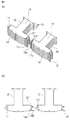
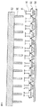
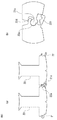
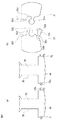
まず、実施の形態1の積層型鉄心を適用する装置例として、電動機の積層型鉄心の構成を図1に基づいて、また積層コアの基本構成を図2に基づいて説明する。なお、図2(a)は積層コアの斜視図、図2(b)は積層コアの平面図である。
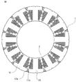
図1は、電動機の積層型鉄心の構成を示す断面図である。積層型鉄心1は複数の積層コア10を環状に連結した構成で、積層コア10には巻線2が巻き回される。積層コア10同士は、コア凸部11aとコア凹部12aが嵌合することで連結されている。
図2(a)、(b)において、積層コア10は磁性材料から成る板状コア片13を軸方向に積層固定したものである。積層コア10は、バックヨーク部14とティース部15から構成される。積層コア10は、第1端部11と第2端部12を備える。第1端部11には連結手段としてのコア凸部11a、第2端部12にはコア凸部11aと連結するためのコア凹部12aが形成されている。積層固定の手段としては、接着、溶接、ダボによるカシメ、あるいはそれらの組合せを使用する。First, as an example of an apparatus to which the laminated iron core of the first embodiment is applied, the configuration of the laminated iron core of the electric motor will be described based on FIG. 1 and the basic configuration of the laminated core will be described based on FIG. 2A is a perspective view of the laminated core, and FIG. 2B is a plan view of the laminated core.
FIG. 1 is a cross-sectional view showing a configuration of a laminated iron core of an electric motor. The
2A and 2B, a
次に積層コア10の連結手順(位置合わせ、仮連結、本連結工程)、巻線工程、および治具を使用した仮連結、本連結工程について説明する。なお、巻線工程の説明では、実施の形態1の積層型鉄心およびその製造方法の特徴を明確にするために、比較例の積層鉄心の巻線工程についても説明する。
Next, the connection procedure (positioning, temporary connection, main connection process) of the
まず、積層コア10の連結前の状態および位置合わせ工程について、図2〜図4に基づいて説明する。なお、図4(a)は位置合わせ工程を示す斜視図、図4(b)は平面図である。
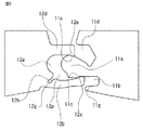
図2(a)、図2(b)に示す隣接する積層コア10同士を、コア凸部11aとコア凹部12aを近づけて、図3の内側係止段差11eと内側係止凸部12eの位置を合わせて図4(a)、(b)の状態とする。この時、図3に示すように顎型突起12bとスライドガイド突起12dで囲われたコア凹部12aの開口幅は、コア凸部11aの幅より大きいため、スムーズに位置合わせすることができる。
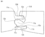
なお、図3において、第1端部11には、さらに外側スライド逃し溝11b、外側係止段差11c、内側スライド逃し溝11d、凸部側端面11f、スプリングバック防止突起11g、およびコア丸め係止凹部11hを備える。また、第2端部12には、さらに外側係止凸部12c、凹部側端面12f、薄肉部12g、および変形逃し溝12hを備える。これらの機能、役割については後で順次説明する。First, the state before the connection of the
2 (a) and 2 (b),
In FIG. 3, the
次に、積層コア10の仮連結工程について、図5〜図8に基づいて説明する。なお、図5(a)、図7(a)は仮連結工程を示す斜視図、図5(b)、図7(b)は平面図である。
顎型突起12bに力を加えて第1の変形をさせることで、積層コア10は図5(a)、(b)に示す状態となる。顎型突起12bの第1の変形により、コア凹部12aの開口幅はコア凸部11aの幅より小さくなり、積層コア10同士を一体として扱うことが可能となる。すなわち、コア凹部12aはU字型となる。
図6は顎型突起12b周辺を拡大した要部拡大図である。顎型突起12bとスライドガイド突起12dとで穴部12pを形成している。顎型突起12b先端の外側係止凸部12cと、スライドガイド突起12d先端の内側係止凸部12eとの幅はコア凸部11aの幅より狭いため、積層コア10同士は外れることはない。
ここで、顎型突起12bは薄肉部12gおよび変形逃がし溝12hを介して板状コア片13とつながっているため、顎型突起12bの変形に必要な力を小さくすることができる。さらに、変形逃がし溝12hが面外変形とスプリングバックを抑制して形状精度を向上させている。Next, the temporary connection process of the lamination | stacking
By applying a force to the jaw-shaped
FIG. 6 is an enlarged view of a main part in which the periphery of the jaw-shaped
Here, since the jaw-shaped
次に、積層コア10同士を近づける方向にスライドさせることで、積層コア10は図7(a)、(b)に示す状態となる。図8は顎型突起12b周辺を拡大した要部拡大図である。外側係止凸部12cと外側係止段差11c、および内側係止凸部12eと内側係止段差11eが噛み合うことで積層コア10同士が分離することを防止する。また、外側スライド逃し溝11bと内側スライド逃し溝11dを設けることで、積層コア10同士を近づける方向にスライドさせることできる。
Next, the
次に、積層コア10の本連結工程について、図9、図10に基づいて説明する。なお、図9(a)は本連結工程を示す斜視図、図9(b)は平面図である。
積層コア10を円環状に変形させる。さらに顎型突起12bに力を加えて、仮連結よりさらに積層コア10内径側に変形(第2の変形)をさせることで、積層コア10は図9(a)(b)の状態となる。すなわち、コア凹部12aはC字型となる。
図10は顎型突起12b周辺を拡大した要部拡大図である。
これと共に、積層コア10を回転させて、片方の積層コア10の凹部側端面12fと、連結する積層コア10の凸部側端面11fを突き合わせることで、積層コア10同士を円環状に配置する。
後に説明する巻線を巻き回した後に複数の積層コア10に対して本連結を行うことで、図1の積層型鉄心1を形成する。Next, the main connection step of the
The
FIG. 10 is an enlarged view of a main part in which the periphery of the jaw-shaped
At the same time, the
After the winding described later is wound, the
図10において、第2の変形後の顎型突起12bは、スプリングバック防止突起11gにより外側スライド逃し溝11b内部に収まる。顎型突起12bの変形には外から治具等により力を加えてもよいし、積層コア10を回転させる力によりスプリングバック防止突起11gで顎型突起12bを押すことで力を加えてもよい。内側スライド逃し溝11dの形状が多角形であるため、積層コア10を回転させても、スライドガイド突起12dは内側スライド逃し溝11dの内部に収まる。さらにスライドガイド突起12dの先端に設けた内側係止凸部12eとコア凸部11aの根元に設けたコア丸め係止凹部11hが噛み合うことで、環状形成後の積層コア10をロックする。
なお、図10において、コア凹部12aがC字型に変形された後、変形逃がし溝12hには空間(逃がし代)が残る。これは逃がし溝の役割をする。In FIG. 10, the jaw-shaped
In FIG. 10, after the
ここで、請求の範囲の記載との対応を説明する。
請求の範囲の凸部はコア凸部11a、凹部はコア凹部12a、凹部の外周側は顎型突起12b、切り欠きは変形逃がし溝12h、穴部は穴部12pである。
請求の範囲の薄肉部は薄肉部12gである。
請求の範囲の凸部の外周側に径方向に伸びる突起部はスプリングバック防止突起11gである。
請求の範囲の凹部の内径側の先端部に設けた突起は内側係止凸部12e、凹部の内径側の先端部に設けた突起と一致する形状の凸部の基部の内径側の谷部はコア丸め係止凹部11hである。Here, correspondence with the description of the claims will be described.
The convex part of the claims is the core
The thin part in the claims is the
The protrusion extending in the radial direction on the outer peripheral side of the convex part in the claims is a
The protrusion provided at the tip on the inner diameter side of the concave portion of the claims is the inner locking
次に、先に説明した仮連結工程の後に行う巻線工程について、図11〜図13に基づいて説明する。
実施の形態1の積層型鉄心およびその製造方法では、図5の仮連結工程で説明したように、積層コア10のティース部15同士を離れる方向にスライドさせることができる。この特徴があるため、積層コア10のティース部15間の巻線スペースを広げて、より多くの巻線を巻き回すことが可能である。Next, the winding process performed after the temporary connection process demonstrated previously is demonstrated based on FIGS.
In the laminated iron core and the manufacturing method thereof according to
実施の形態1の積層型鉄心およびその製造方法のこの特徴を明確にするため、まず比較例の積層鉄心の巻線工程と丸め工程とについて図11、図12で説明する。
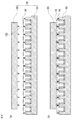
図11(a)、(b)に比較例の積層コア110の巻線工程を示す。ここで、図11(b)は図11(a)の右端の2個の積層コア110を拡大した図である。
比較例の積層コア110は、スリット部110aと薄肉部110bを介して繋がっている。積層コア110は、バックヨーク部114とティース部115から構成される。
積層コア110は、巻線機コアチャック51で固定される。巻線機ノズル50を用いて巻線2を巻き回した後、薄肉部110bを塑性変形させて円環状に配置し、積層コア110をコア端部接合110cにより固定し、図12に示す円環状の比較例の鉄心装置101を形成する。コア端部接合110cには溶接や接着等が使用される。In order to clarify this feature of the laminated core and the manufacturing method thereof according to the first embodiment, first, the winding process and the rounding process of the laminated core of the comparative example will be described with reference to FIGS.
FIGS. 11A and 11B show a winding process of the
The
The
ここで比較例の積層コア110の課題について説明する。図11(b)において、右端のティース部115に巻線2を巻き回した後、左側のティース部115に巻線2を巻き回す際に、巻線機ノズル50と巻線2が干渉する。積層コア間距離Aを拡大すると、比較例の鉄心装置101の外径も拡大し、その結果電動機が大型化する。比較例の鉄心装置101の外径を変更しない場合は、巻線するコイルの数を減らす必要があり、その結果電動機の効率が低下する。
Here, the problem of the
これに対して、実施の形態1の積層型鉄心およびその製造方法の巻線工程を図13(a)、(b)に示す。図13(a)は、積層コア10のティース部15間の巻線スペースを広げて巻線を巻き回す状態を示す。図13(b)は巻線を終了して、積層コア10のティース部15間の巻線スペースを狭めた状態を示す。なお、比較例の積層コア110用の巻線機コアチャック51に対して、実施の形態1の積層コア10用を巻線機コアチャック52としている。
積層コア10を巻線機コアチャック52で固定した後、それぞれ離れる方向にスライドさせて積層コア間距離B(B>A)とすることで、巻線2と巻線機ノズル50は干渉しない。このため、比較例の積層コア110より多くの巻線を巻き回すことができ、その結果電動機の効率を向上させることができる。
巻線後は図13(b)に示すように、積層コア10同士を近づける方向にスライドさせて、積層コア間距離Bを積層コア間距離Aまで縮めることで、比較例の積層コア110と同じ積層コア間距離Aとなり、本連結工程により図1の積層型鉄心1を形成する。実施の形態1の積層型鉄心1は比較例の鉄心装置101と同一の外径で、より多くのコイルを巻線できる。
したがって、実施の形態1の積層型鉄心およびその製造方法は、巻線作業を容易化して、線積率を向上させることができる。In contrast, FIGS. 13A and 13B show the winding process of the laminated iron core and the manufacturing method thereof according to the first embodiment. FIG. 13A shows a state in which the winding space is expanded between the
After the
After winding, as shown in FIG. 13B, the
Therefore, the laminated iron core and the manufacturing method thereof according to
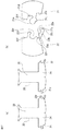
次に、仮連結工程における治具の適用について、図14、図15に基づいて説明する。
まず、仮連結治具パンチを1台使用する場合を図14で説明する。
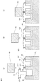
図14(a)は、連結する一対の積層コア10を、仮連結治具60へ配置する方法を示す。図14(b)は、積層コア10の位置合わせした状態を示す。図14(c)は、顎型突起12bの第1の変形を行い、仮連結が完了した状態を示す。Next, application of the jig in the temporary connection step will be described with reference to FIGS.
First, the case where one temporary connecting jig punch is used will be described with reference to FIG.
FIG. 14A shows a method of arranging a pair of
仮連結治具60は、積層コア10を位置決めする仮連結治具ベース61と、顎型突起12bを押して変形させるための仮連結治具パンチ63とを備える。
仮連結治具ベース61には、コア位置決め突起62が形成されており、積層コア10の凸部側端面11fと凹部側端面12fをコア位置決め突起62に合わせて位置決めを行う(図14(b)の状態)。次に仮連結治具パンチ63を用いて顎型突起12bに力を加えて第1の変形を行い、仮連結を完了する(図14(c)の状態)。
なお、凸部側端面11fの先端部は直角または傾斜を有する。また、凹部側端面12fは基部の内径側に直角または傾斜を有する。
ここで、請求の範囲の凸部の基部の内径側に設けた突起は凸部側端面11f、凹部を構成する内径側の突起は凹部側端面12fである。The
A
In addition, the front-end | tip part of the convex part
Here, the protrusion provided on the inner diameter side of the base of the convex portion in the claims is the convex-
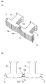
次に、一括仮連結治具を使用する場合を図15で説明する。図15(a)は、複数個の積層コア10の位置合わせを行い、治具に設置した状態を示す。図15(b)は、顎型突起12bの第1の変形を一括して行い仮連結を完了した状態を示す。ここで、仮連結された積層コア10を仮連結した積層コア16とする。
図14の仮連結治具60は、1箇所ずつ仮連結を行う治具であったが、図15に示す一括仮連結治具64は、複数の連結箇所を同時に一括で仮連結を行うことができる。
一括仮連結治具ベース65に、積層コア10を複数個並べ(図15(a)の状態)、一括仮連結治具パンチ66により複数の顎型突起12bに対して第1の変形を同時に行い、仮連結した積層コア16を形成できる(図15(b)の状態)。この結果、積層コア10当たりの仮連結を行う時間を短縮することができる。Next, the case where the collective temporary connecting jig is used will be described with reference to FIG. FIG. 15A shows a state where a plurality of
The
A plurality of
次に、複数の積層コア10に対して、一括して巻線2を巻き回す巻線工程について、図16〜図18に基づいて説明する。ここで、巻線された積層コア10を巻線後の積層コア17とする。
図13の巻線工程は巻線機ノズル50が1本の例を示したが、図16〜図18に示すように仮連結した積層コア16を一括で巻線することもできる。巻線機本体(図示なし)は複数の巻線機コアチャック52と、巻線機コアチャック52をスライド可能な状態で固定する巻線機コアチャックベース54と、複数の巻線機ノズル50と、巻線機ノズル50を固定する巻線機ノズルホルダ53とを備える。まず、図16に示すように仮連結した積層コア16を巻線機コアチャック52に取り付ける。この時、仮連結した積層コア16は積層コア10のティース部15間の距離を縮める方向にスライドさせて連結部の接触点を増やすことで、コア全体の剛性を向上させ、搬送や巻線機コアチャック52への取付けを容易にしている。次に図17に示すように、巻線機コアチャック52を積層コア10のティース部15間の距離を広げる方向にスライドさせた後、巻線機ノズルホルダ53に取付けた複数の巻線機ノズル50を用いて、仮連結した積層コア16の全ティース部15に同時に巻線2を巻き回す。巻線完了後、図18に示すように、巻線機ノズル50を退避させた後、巻線機コアチャック52を積層コア10のティース部15間の距離を縮める方向にスライドさせて、巻線後の積層コア17を巻線機コアチャック52から取り外す。Next, a winding process for winding the winding 2 around the plurality of
The winding process of FIG. 13 shows an example in which the winding
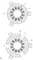
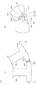
次に、巻線後の積層コア17の連結部に本連結を行い、円環状の積層型鉄心1を形成する本連結工程における治具の適用について、図19、図20に基づいて説明する。
まず、本連結押し爪70を適用して本連結を行う場合を図19で説明する。
図19(a)に示すように、巻線後の積層コア17を円環状に丸め、外周側から本連結押し爪70で力を加えて、巻線後の積層コア17の外径から飛び出た顎型突起12bに第2の変形を行うことで本連結を行い、図19(b)に示すように積層型鉄心1を形成する。
図19では、本連結押し爪70を3台としているが、2台でも可能であるし、あるいは4台以上としてもよい。Next, the application of the jig in the main connection step in which main connection is performed to the connection portion of the
First, a case where the main
As shown in FIG. 19A, the
In FIG. 19, there are three main connecting
次に、本連結芯棒71および本連結押しローラ72を適用して本連結を行う場合を図20で説明する。ここで、図20(a)は治具の構成を示し、図20(b)、(c)は、本連結の要領の説明図である。
本連結用治具は、巻線後の積層コア17の内径を位置決めするための本連結芯棒71と、顎型突起12bに力を加えて変形させるための本連結押しローラ72とで構成される。
図20(b)において、本連結芯棒71に対して、巻線後の積層コア17を巻きつける。このとき、本連結芯棒71に電磁石、または永久磁石を用いて磁気吸引力を発生させることで積層コア10を固定することもできる。次に本連結押しローラ72に力を加えて、巻線後の積層コア17を本連結芯棒71へ押し付け、巻線後の積層コア17の外径から飛び出している顎型突起12bに第2の変形を行い、本連結を行う。図20(c)の矢印方向へ、本連結芯棒71と巻線後の積層コア17を回転させることで、本連結押しローラ72により、連続して本連結を行うことができる。このため、短時間での本連結を行うことが可能となる。Next, a case where the main connection is performed by applying the main
The connecting jig includes a main connecting
In FIG. 20B, the
次に上記で説明した本実施の形態1の積層型鉄心の製造方法について、図21のフローチャートに基づいて説明する。
なお、本実施の形態1の積層型鉄心の製造方法は、積層コア10の第1端部11にコア凸部11aを有し、積層コア10の第2端部12にコア凹部12aを有し、積層コア10の第2端部12のコア凹部12aは顎型突起12bとスライドガイド突起12dとを有し、顎型突起12bは、顎型突起12bとスライドガイド突起12dとで第1端部11のコア凸部11aを囲む穴部12pを形成するように2段階の変形が可能な構造の積層コア10を用いるものである。第1の変形は、積層コア10同士が外れることなく、積層コア10同士をスライドさせることができ、第2の変形は、積層コア10同士を連結する。実施の形態1の積層型鉄心の製造方法は、以下のステップ1(S01)からステップ4(S04)の工程から成る。Next, the manufacturing method of the laminated core of the first embodiment described above will be described based on the flowchart of FIG.
The method for manufacturing the laminated core of the first embodiment has a core
ステップ1(S01)の位置合わせ工程では、第1の積層コア10のコア凸部11aを第2の積層コア10のコア凹部12aに挿入して、第1の積層コア10との第2の積層コア10との位置合わせを行う。
In the alignment process of Step 1 (S01), the
ステップ2(S02)の仮連結工程では、積層コア10の顎型突起12bに第1の変形を行い、コア凹部12aの開口幅を縮小させる。顎型突起12bとスライドガイド突起12dとで穴部12pを形成する。これで積層コア同士10が外れることが防止される。
In the temporary connection step of Step 2 (S02), the first deformation is performed on the jaw-shaped
ステップ3(S03)の巻線工程では、積層コア10同士をスライドさせて、ティース部15の間隔を広げた状態で積層コア10のティース部15に巻線2を巻き回し、巻線後、積層コア10同士をスライドさせて、ティース部15の間隔を狭める。
In the winding process of Step 3 (S03), the
ステップ4(S04)の本連結工程では、巻線2が巻き回された複数の積層コア10を環状に配列し、積層コア10の顎型突起12bに第2の変形を行って連結固定して、積層型鉄心1を形成する。
In the main connecting step of Step 4 (S04), the plurality of
以上説明したように、実施の形態1は、積層コアの第1端部にコア凸部を有し、積層コアの第2端部にコア凹部を有し、積層コアの第2端部のコア凹部は顎型突起とスライドガイド突起とを有し、顎型突起はスライドガイド突起とで第1端部のコア凸部を囲む穴部を形成するように2段階の変形が可能な構造であり、第1の変形は、積層コア同士が外れることなく、積層コア同士をスライドさせることができ、第2の変形は、積層コア同士を連結して円環状の積層型鉄心を形成する構造の積層型鉄心、および位置合わせ工程と、仮連結工程と、巻線工程と、本連結工程と、を備える積層型鉄心の製造方法に関するものである。
このため、実施の形態1の積層型鉄心およびその製造方法は、積層コアを容易に連結でき、金型を小型化できる。さらに、巻線作業を容易化して、線積率を向上させることができる。As described above, the first embodiment has a core convex portion at the first end of the laminated core, a core concave portion at the second end of the laminated core, and a core at the second end of the laminated core. The recess has a jaw projection and a slide guide projection, and the jaw projection has a structure that can be deformed in two stages so as to form a hole surrounding the core projection at the first end with the slide guide projection. In the first modification, the laminated cores can be slid without being separated from each other, and in the second modification, the laminated cores are connected to each other to form an annular laminated iron core. The present invention relates to a method for manufacturing a laminated core including a mold core, an alignment step, a temporary connection step, a winding step, and a main connection step.
For this reason, the laminated iron core and the manufacturing method thereof according to the first embodiment can easily connect the laminated cores and reduce the size of the mold. Furthermore, the winding work can be facilitated and the line product ratio can be improved.
実施の形態2.
実施の形態2の積層型鉄心は、実施の形態1の積層型鉄心に対して、仮連結時における積層コア同士をスライドさせる構造を除いて、積層型鉄心の構造およびその製造方法を簡素化したものである。
The laminated iron core according to the second embodiment has a simplified structure of the laminated iron core and a method for manufacturing the laminated iron core except for the structure in which the laminated cores are slid between the laminated iron cores according to the first embodiment. Is.
以下、実施の形態2の積層型鉄心およびその製造方法について、積層コアの連結前の状態を示す平面図と要部拡大図である図22、位置合わせ工程を示す平面図と要部拡大図である図23、仮連結工程を示す平面図と要部拡大図である図24、および本連結工程を示す平面図と要部拡大図である図25に基づいて、実施の形態1との差異を中心に説明する。 Hereinafter, with respect to the laminated iron core of the second embodiment and the manufacturing method thereof, FIG. 22 is a plan view showing a state before connection of the laminated cores and FIG. 22 is an enlarged view of the main part, and a plan view and an enlarged view of the main part showing the alignment step. Based on FIG. 23, FIG. 24, which is a plan view showing the provisional connection step, and FIG. 24, which is an enlarged view of the main portion, and FIG. 25, which is a plan view showing the main connection step, and FIG. The explanation is centered.
積層コア20の連結手順(位置合わせ、仮連結、本連結工程)について順次説明する。
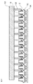
まず、積層コア20の連結前の状態および位置合わせ工程について、図22、図23に基づいて説明する。なお、図22(a)は積層コア20の平面図、図22(b)は要部拡大図である。また図23(a)は位置合わせ工程を示す平面図、図23(b)は要部拡大図である。The connection procedure (positioning, temporary connection, main connection process) of the
First, the state before the connection of the
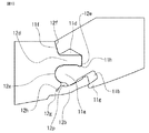
図22(a)において、積層コア20は磁性材料から成る板状コア片を軸方向に積層固定したものである。積層コア20は、バックヨーク部24とティース部25から構成される。積層コア20は、第1端部21と第2端部22を備える。第1端部21には連結手段としてのコア凸部21a、第2端部22にはコア凸部21aと連結するためのコア凹部22aが形成されている。積層固定の手段としては、接着、溶接、ダボによるカシメ、あるいはそれらの組合せを使用する。
In FIG. 22A, a
図22(b)において、積層コア20の第1端部21には、コア凸部21aの両側に外側スライド逃し溝21bと内側スライド逃し溝21dとを備える。コア凸部21aの一部に連結係止凸部21jを備えている。また、内径側には積層コア20を円環状に位置決めするための凸部側端面21fを備える。
一方、積層コア20の第2端部22は、コア凹部22aを備え、その両側には顎型突起22bとスライドガイド突起22dとを備える。顎型突起22bの根元には薄肉部22gと変形逃し溝22hとを備える。顎型突起22bの先端部には外側係止凸部22cと、内径側には本連結工程において嵌合するための本連結係止溝22jと、仮連結工程において連結係止凸部21jを位置決めするための仮連結係止突起22kとを備える。またスライドガイド突起22dの内径側には凸部側端面21fと位置決めするための凹部側端面22fとを備える。22B, the
On the other hand, the
隣接する積層コア20同士を近づけてコア凸部21aとコア凹部22aとの位置を合わせて図23(a)、(b)の状態とする。この時、顎型突起22bとスライドガイド突起22dで囲われたコア凹部22aの開口幅は、コア凸部21aの幅より大きいため、スムーズに位置合わせすることができる。
The adjacent
次に、積層コア20の仮連結工程について、図24に基づいて説明する。なお、図24(a)は仮連結工程を示す平面図、図24(b)は要部拡大図である。ここで、仮連結された積層コア20を仮連結した積層コア26とする。
顎型突起22bに力を加えて第1の変形をさせることで、積層コア20は図24(a)に示す状態となる。顎型突起22bとスライドガイド突起22dとで穴部22pを形成している。顎型突起22bの変形により、コア凸部21aは、スライドガイド突起22d、仮連結係止突起22k、およびコア凹部22aにより挟まれることで固定される。
さらに外側スライド逃し溝21bと外側係止凸部22cとが接することで、積層コア20同士の回転についても抑制される。これにより、積層コア20を仮連結した積層コア26は比較例の積層コア110と同様に一体として容易に搬送や巻線作業を実施できる。
ここで、顎型突起22bは薄肉部22gおよび変形逃がし溝22hを介して板状コア片とつながっており、顎型突起22bの変形に必要な力を小さくすることができる。さらに、変形逃がし溝22hが面外変形とスプリングバックを抑制して形状精度を向上させている。Next, the temporary connection process of the
By applying a force to the jaw-shaped
Furthermore, the rotation of the
Here, the jaw-shaped
次に、積層コア20の本連結工程について、図25に基づいて説明する。なお、図25(a)は本連結工程を示す平面図、図25(b)は要部拡大図である。
積層コア20を円環状に変形させる。さらに顎型突起22bに力を加えて、仮連結よりさらに積層コア20内径側に変形(第2の変形)をさせることで、積層コア20は図25(a)の状態となる。
具体的には、積層コア20を回転させて、積層コア20の第2端部22の凹部側端面22fと、積層コア20の第1端部21の凸部側端面21fとを突き合わせることで、積層コア20同士を円環状に配置する。この後に、顎型突起22bに力を加えて、仮連結よりさらに積層コア20内径側に変形させて、積層コア20を円環状に固定する。
図25(b)に示すように、顎型突起22bの内径側にある本連結係止溝22jと連結係止凸部21jとが嵌合し、コア凸部21aの根元部は外側係止凸部22cとスライドガイド突起22dにより挟まれることで、積層コア20同士が固定される。この時、スライドガイド突起22dは内側スライド逃し溝21dの内部に収まる。
なお、請求の範囲の凹部を構成する外径側の突起の内径基部側の張り出しは仮連結係止突起22k、凹部を構成する外径側の突起の内径先端側の谷部は本連結係止溝22j、凸部の基部の外径側の張り出しは連結係止凸部21jである。Next, the main connecting step of the
The
Specifically, by rotating the
As shown in FIG. 25 (b), the
Note that the protrusion on the inner diameter base side of the outer diameter side projection constituting the concave portion of the claims is the temporary
なお、巻線作業については、実施の形態1で説明した比較例の積層コア110について説明した内容と同様であるため省略する。
実施の形態2の積層型鉄心は積層コア毎に分割されているため、積層コアを小さな金型で製造でき、金型コストを低減できる。一方で、巻線工程は比較例の積層コア110と同じ設備を使用できるため、設備投資コストを低く抑えることが可能である。The winding work is omitted because it is the same as that described for the
Since the laminated iron core of
次に上記で説明した本実施の形態2の積層型鉄心の製造方法について説明する。なお、フローチャートは実施の形態1の図21と同じであるため、図21を参照して説明する。
なお、実施の形態1と区別するため、ステップ番号は10番台として説明する。
本実施の形態2の積層型鉄心の製造方法は、積層コア20の第1端部21にコア凸部21aを有し、積層コア20の第2端部22にコア凹部22aを有し、積層コア20の第2端部22のコア凹部22aは顎型突起22bとスライドガイド突起22dとを有し、顎型突起22bは、顎型突起22bとスライドガイド突起22dとで第1端部21のコア凸部21aを囲む穴部を形成するように2段階の変形が可能な構造である積層コア20を用いるものである。実施の形態2の積層型鉄心の製造方法は、以下のステップ11(S11)からステップ14(S14)の工程から成る。Next, a method for manufacturing the laminated iron core according to the second embodiment described above will be described. The flowchart is the same as FIG. 21 of the first embodiment, and will be described with reference to FIG.
In order to distinguish from the first embodiment, the step number will be described as 10th.
The manufacturing method of the laminated core of the second embodiment includes a core
ステップ11(S11)の位置合わせ工程では、第1の積層コア20のコア凸部21aを第2の積層コア20のコア凹部22aに挿入して第1の積層コア20との第2の積層コア20との位置合わせを行う。
In the alignment step of step 11 (S11), the core
ステップ12(S12)の仮連結工程では、積層コア20の顎型突起22bに第1の変形を行い、コア凹部22aの開口幅を縮小させる。顎型突起22bとスライドガイド突起22dとで穴部22pを形成する。これで積層コア同士20が外れることが防止される。
In the temporary connection step of step 12 (S12), the first deformation is performed on the jaw-shaped
ステップ13(S13)の巻線工程では、積層コア20のティース部25に巻線2を巻き回す。
In the winding step of step 13 (S13), the winding 2 is wound around the
ステップ14(S14)の本連結工程では、巻線が巻き回された複数の積層コア20を環状に配列し、積層コア20の顎型突起22bに第2の変形を行い、連結固定して積層型鉄心を形成する。
In the main connecting step of step 14 (S14), the plurality of
なお、実施の形態2の積層コア20に対しても、実施の形態1で説明した仮連結工程における一括仮連結治具(一括仮連結治具ベース、一括仮連結治具パンチ)を使用することができる。また、実施の形態1で説明した本連結工程における本連結用治具(本連結押し爪、または本連結芯棒と本連結押しローラ)を使用することができる。
For the
以上説明したように、実施の形態2の積層型鉄心は、実施の形態1の分割積層鉄心に比較して、仮連結時における積層コア同士をスライドさせる構造を除いて、簡素化したものである。このため、実施の形態2の積層型鉄心およびその製造方法は、積層コアを容易に連結でき、金型を小型化することができると共に設備投資コストを低く抑えることができる。 As described above, the laminated iron core according to the second embodiment is simplified as compared with the divided laminated iron core according to the first embodiment except for a structure in which laminated cores are slid together during temporary connection. . For this reason, the laminated iron core and the manufacturing method thereof according to the second embodiment can easily connect the laminated cores, reduce the size of the mold, and reduce the capital investment cost.
実施の形態3.
実施の形態3は、実施の形態2の積層型鉄心に対して、顎型突起の変形を1段階のみとして、積層型鉄心の構造およびその製造方法を簡素化したものである。Embodiment 3 FIG.
In the third embodiment, the structure of the laminated iron core and the manufacturing method thereof are simplified by changing the jaw-shaped protrusions to only one stage with respect to the laminated iron core of the second embodiment.
以下、実施の形態3の積層型鉄心およびその製造方法について、積層コアの連結前の状態を示す平面図と要部拡大図である図26、位置合わせ工程を示す平面図と要部拡大図である図27、連結工程を示す平面図と要部拡大図である図28、および丸め工程を示す平面図と要部拡大図である図29に基づいて、実施の形態1、2との差異を中心に説明する。
なお、実施の形態1、2では、積層コアの連結を2段階で行ったため、仮連結、本連結と区別した。実施の形態3では、積層コアの連結は1段階であるため、区別せずに連結工程としている。また、積層コアを円環状に連結して、積層型鉄心を形成する工程を丸め工程としている。Hereinafter, with respect to the laminated iron core of the third embodiment and the manufacturing method thereof, FIG. 26 is a plan view showing a state before connection of laminated cores and FIG. Based on FIG. 27, FIG. 28, which is a plan view showing the connecting step, FIG. 28, which is an enlarged view of the main part, and FIG. 29, which is a plan view showing the rounding step, and FIG. The explanation is centered.
In the first and second embodiments, the laminated cores are connected in two stages, so that they are distinguished from the temporary connection and the main connection. In Embodiment 3, since the connection of the laminated cores is in one stage, the connection process is performed without distinction. Further, the step of forming the laminated core by connecting the laminated cores in an annular shape is a rounding step.
積層コア30の連結手順(位置合わせ、連結工程)および丸め工程について順次説明する。
まず、積層コア30の連結前の状態および位置合わせ工程について、図26、図27に基づいて説明する。なお、図26(a)は積層コア30の平面図、図26(b)は要部拡大図である。また図27(a)は位置合わせ工程を示す平面図、図27(b)は要部拡大図である。The connection procedure (positioning and connection process) and the rounding process of the
First, the state before the connection of the
図26(a)において、積層コア30は磁性材料から成る板状コア片を軸方向に積層固定したものである。積層コア30は、バックヨーク部34とティース部35から構成される。積層コア30は、第1端部31と第2端部32を備える。第1端部31には連結手段としてのコア凸部31a、第2端部32にはコア凸部31aと連結するためのコア凹部32aが形成されている。積層固定の手段としては、接着、溶接、ダボによるカシメ、あるいはそれらの組合せを使用する。
In FIG. 26A, a
図26(b)において、積層コア30の第1端部31には、コア凸部31aの内径側に内側スライド逃し溝31dと、積層コア30を円環状に位置決めするための凸部側端面31fとを備える。またコア凸部31aは一部を窪ませた顎型突起逃し凹部31mを備える。
一方、積層コア30の第2端部32には、コア凹部32aの両側には顎型突起32bとスライドガイド突起32dとを備える。顎型突起32bの根元には薄肉部32gと変形逃し溝32hとを備える。また顎型突起32bの内径側には連結時に顎型突起逃し凹部31mと嵌合する顎型突起与圧付加部32mを備える。さらにスライドガイド突起32dの内径側には円環状に位置決めするための凹部側端面32fを備える。In FIG. 26B, the
On the other hand, the
隣接する積層コア30同士を近づけてコア凸部31aとコア凹部32aとの位置を合わせて図27(a)、(b)の状態とする。この時、顎型突起32bとスライドガイド突起32dで囲われたコア凹部32aの開口幅は、コア凸部31aの幅より大きいため、スムーズに位置合わせすることができる。
The adjacent
次に、積層コア30の連結工程について、図28に基づいて説明する。なお、図28(a)は連結工程を示す平面図、図28(b)は要部拡大図である。
顎型突起32bに力を加えて変形をさせることで、積層コア30は図28(a)に示す状態となる。顎型突起32bの変形により、顎型突起32bとスライドガイド突起32dとで穴部32pを形成する。コア凸部31aは、顎型突起32b、スライドガイド突起32d、およびコア凹部32aにより挟まれることで固定される。
さらに顎型突起与圧付加部32mと顎型突起逃し凹部31mとが嵌合することで、積層コア30同士の回転についても抑制される。これにより、連結した積層コア38は、実施の形態1で説明した比較例の積層コア110と同様に一体として容易に搬送や巻線を実施できる。
ここで、顎型突起32bは薄肉部32gおよび変形逃がし溝32hを介して板状コア片とつながっており、顎型突起32bの変形に必要な力を小さくすることができる。さらに、変形逃がし溝32hが面外変形とスプリングバックを抑制して形状精度を向上させている。Next, the connection process of the
By applying a force to the jaw-shaped
Furthermore, the rotation of the
Here, the
次に、積層コア30の丸め工程について、図29に基づいて説明する。なお、図29(a)は丸め工程を示す平面図、図29(b)は要部拡大図である。
積層コア30を、図29(a)に示すように回転させて、凹部側端面32fと凸部側端面31fを突き合わせて円環状に変形させる。
図28(b)では顎型突起与圧付加部32mと顎型突起逃し凹部31mが密着していた。これに対して、図29(b)では相対的に回転することで距離が変化し、顎型突起与圧付加部32mの一部が顎型突起逃し凹部31mに対して食い込む部分である顎型突起締め代32nが生じる。実際には顎型突起32bが外径側に弾性変形することで顎型突起締め代32nはゼロとなるが、顎型突起逃し凹部31mに対して弾性変形分の与圧を与える。この与圧により、積層コア30同士を固定することができる。Next, the rounding process of the
The
In FIG. 28 (b), the jaw-shaped projection pressurizing
なお、巻線作業は、連結工程後に行うが、比較例の積層コア110で説明した内容と同様であるため省略する。
実施の形態3の積層型鉄心は、実施の形態1、2と同様に、積層コアを小さな金型で製造できるため、金型コストを低減できる。また、巻線工程は比較例の積層コア110と同じ設備を使用できるため、設備投資コストを低く抑えることができる。さらに、連結工程が1回のみとなるから、実施の形態1、2と比較して製造工数を削減することができる。The winding work is performed after the connecting step, but is omitted because it is the same as the content described in the
Since the laminated core of the third embodiment can manufacture the laminated core with a small mold as in the first and second embodiments, the mold cost can be reduced. Moreover, since the same equipment as the
以上説明したように、実施の形態3は、顎型突起の変形を1段階のみとして、積層型鉄心の構造および製造方法を簡素化したものである。このため、実施の形態3の積層型鉄心およびその製造方法は、積層コアを容易に連結でき、金型を小型化することができる。また、設備投資コストを低く抑えるとともに、製造工数を削減することができる。 As described above, the third embodiment simplifies the structure and the manufacturing method of the laminated iron core with only one step of the deformation of the jaw projection. For this reason, the laminated core and the manufacturing method thereof according to Embodiment 3 can easily connect the laminated cores, and can downsize the mold. In addition, the capital investment cost can be kept low and the number of manufacturing steps can be reduced.
なお、本発明は、その発明の範囲内において、各実施の形態を自由に組み合わせたり、実施の形態を適宜、変形、省略したりすることが可能である。 Note that the present invention can be freely combined with each other within the scope of the invention, and the embodiments can be modified or omitted as appropriate.
この発明は、積層コアを容易に連結でき、金型を小型化できるため、電動機等の積層型鉄心およびその製造方法を広く適用できる。 Since this invention can connect a laminated core easily and can reduce a metal mold | die, laminated iron cores, such as an electric motor, and its manufacturing method can be applied widely.
Claims (13)
前記積層コアの一方の端部に凸部を有し、前記積層コアの他方の端部に凹部を有し、
前記凹部の外周側の一部に切り欠きを有し、
前記凹部は、前記凸部を囲む穴部を形成するようにC字型に変形可能な構造を持ち、
前記切り欠きを有する前記凹部の前記外周側の一部は薄肉部であり、
前記切り欠きは、前記積層コア同士をスライド可能とする逃がし溝を有し、
前記凹部は2段階の変形が可能な構造であり、
前記凹部がU字型となることで、前記積層コア同士を周方向にスライド可能な状態で連結させる第1段階の変形と、
前記凹部が前記C字型となることで、前記積層コア同士が動かない状態で固定する第2段階の変形を有し、
前記積層コア同士が外れることなく、前記積層コアのティース部同士を離れる方向にスライドさせることができる積層型鉄心。 A laminated iron core that is formed by connecting a plurality of laminated cores in which plate-shaped core pieces having the same shape are laminated and fixed,
A convex portion at one end of the laminated core, a concave portion at the other end of the laminated core,
Having a notch in a part of the outer peripheral side of the recess,
The concave portion has a structure that can be deformed into a C-shape so as to form a hole surrounding the convex portion,
A part of the outer peripheral side of the recess having the notch is a thin part,
The notch may have a relief groove to allow sliding the laminated cores,
The recess is a structure that can be deformed in two stages,
A first-stage deformation that connects the laminated cores in a slidable state in the circumferential direction because the concave portion is U-shaped,
Since the concave portion becomes the C-shape, there is a second stage deformation in which the laminated cores are fixed in a state where they do not move,
A laminated iron core that can be slid in a direction in which the tooth portions of the laminated core are separated from each other without detaching the laminated cores.
前記積層コアの一方の端部に凸部を有し、前記積層コアの他方の端部に凹部を有し、A convex portion at one end of the laminated core, a concave portion at the other end of the laminated core,
前記凹部の外周側の一部に切り欠きを有し、Having a notch in a part of the outer peripheral side of the recess,
前記凹部は、前記凸部を囲む穴部を形成するようにC字型に変形可能な構造を持ち、The concave portion has a structure that can be deformed into a C-shape so as to form a hole surrounding the convex portion,
前記切り欠きを有する前記凹部の前記外周側の一部は薄肉部であり、A part of the outer peripheral side of the recess having the notch is a thin part,
前記切り欠きは、前記積層コア同士をスライド可能とする逃がし溝を有し、The notch has an escape groove that allows the laminated cores to slide together,
前記凹部の前記外周側の先端部と接する位置に、前記凸部の外周側に径方向に伸びる突起部を有する構造を有し、At a position in contact with the outer peripheral side tip of the concave portion, it has a structure having a protrusion extending radially on the outer peripheral side of the convex portion,
前記凹部が前記C字型に変形後にスプリングバックによって変形が戻ることを防止する積層型鉄心。A laminated iron core that prevents the recess from returning to deformation by a springback after being deformed into the C-shape.
前記凹部がU字型となることで、前記積層コア同士を周方向にスライド可能な状態で連結させる第1段階の変形と、
前記凹部が前記C字型となることで、前記積層コア同士が動かない状態で固定する第2段階の変形を有する、請求項2に記載の積層型鉄心。 The recess is a structure that can be deformed in two stages,
A first-stage deformation that connects the laminated cores in a slidable state in the circumferential direction because the concave portion is U-shaped,
The laminated iron core according to claim 2 , which has a second-stage deformation in which the recessed core is fixed in a state where the laminated cores do not move by being formed into the C shape.
前記凹部を構成する内径側の突起の基部の内径側に、直角または傾斜を有する構造とする、請求項1から請求項4のいずれか1項に記載の積層型鉄心。 Protrusion is provided on the inner diameter side of the base of the protrusion, and the tip of the protrusion has a right angle or an inclined structure,
The laminated iron core according to any one of claims 1 to 4, wherein a structure having a right angle or an inclination is provided on an inner diameter side of a base portion of a protrusion on an inner diameter side constituting the concave portion.
前記積層コアの一方の端部に凸部を有し、前記積層コアの他方の端部に凹部を有し、
前記凹部の外周側の一部に切り欠きを有し、
前記凹部は、前記凸部を囲む穴部を形成するようにC字型に変形可能な構造を持ち、
前記凹部は2段階の変形が可能な構造であり、
前記凹部がU字型となることで、前記積層コア同士を周方向にスライド可能な状態で連結させ、前記積層コア同士が外れることなく、前記積層コアのティース部同士を離れる方向にスライドさせることができる第1段階の変形と、
前記凹部が前記C字型となることで、前記積層コア同士が動かない状態で固定する第2段階の変形を有する積層型鉄心。 A laminated iron core that is formed by connecting a plurality of laminated cores in which plate-shaped core pieces having the same shape are laminated and fixed,
A convex portion at one end of the laminated core, a concave portion at the other end of the laminated core,
Having a notch in a part of the outer peripheral side of the recess,
The concave portion has a structure that can be deformed into a C-shape so as to form a hole surrounding the convex portion,
The recess is a structure that can be deformed in two stages,
By making the concave portion U-shaped, the laminated cores are connected in a slidable state in the circumferential direction, and the laminated cores are slid in a direction away from each other without coming off. a modification of the first stage where Ru can,
A laminated iron core having a second stage of deformation in which the laminated cores are fixed in a state where the laminated cores do not move because the concave portion becomes the C-shape.
前記積層コアの一方の端部に凸部を有し、前記積層コアの他方の端部に凹部を有し、
前記凹部の外周側の一部に切り欠きを有し、
前記凹部は、前記凸部を囲む穴部を形成するようにC字型に変形可能な構造を持ち、
前記凹部の前記外周側の先端部と接する位置に、前記凸部の外周側に径方向に伸びる突起部を有する構造を有し、
前記凹部が前記C字型に変形後にスプリングバックによって変形が戻ることを防止する積層型鉄心。 A laminated iron core that is formed by connecting a plurality of laminated cores in which plate-shaped core pieces having the same shape are laminated and fixed,
A convex portion at one end of the laminated core, a concave portion at the other end of the laminated core,
Having a notch in a part of the outer peripheral side of the recess,
The concave portion has a structure that can be deformed into a C-shape so as to form a hole surrounding the convex portion,
At a position in contact with the outer peripheral side tip of the concave portion, it has a structure having a protrusion extending radially on the outer peripheral side of the convex portion,
A laminated iron core that prevents the recess from returning to deformation by a springback after being deformed into the C-shape.
前記積層コアの一方の端部に凸部を有し、前記積層コアの他方の端部に凹部を有し、
前記凹部の外周側の一部に切り欠きを有し、
前記凹部は、前記凸部を囲む穴部を形成するようにC字型に変形可能な構造を持ち、
前記凹部を構成する外径側の突起において、前記突起の内径基部側に張り出しを設け、内径先端側に谷部を設ける構造とし、
一方前記凸部の基部の外径側に張り出しを有する構造とし、
前記積層コア同士を直線状態に並べた時に、前記凹部の前記張り出しと前記凸部の前記張り出しが接触し、前記積層コア同士が外れることなく、前記積層コアのティース部同士を離れる方向にスライドさせることができ、
前記積層コア同士を円環状態に並べた時に、前記凹部の前記谷部と前記凸部の前記張り出しが嵌合する構造を有する積層型鉄心。 A laminated iron core that is formed by connecting a plurality of laminated cores in which plate-shaped core pieces having the same shape are laminated and fixed,
A convex portion at one end of the laminated core, a concave portion at the other end of the laminated core,
Having a notch in a part of the outer peripheral side of the recess,
The concave portion has a structure that can be deformed into a C-shape so as to form a hole surrounding the convex portion,
In the protrusion on the outer diameter side constituting the recess, a protrusion is provided on the inner diameter base side of the protrusion, and a trough is provided on the inner diameter tip side.
On the other hand, it has a structure having an overhang on the outer diameter side of the base of the convex part,
When the laminated cores are arranged in a straight line, the protrusions of the concave portions and the protrusions of the convex portions are in contact with each other, and the laminated cores are slid in directions away from each other without coming off. It is possible,
A laminated iron core having a structure in which when the laminated cores are arranged in an annular state, the trough portions of the concave portions and the protrusions of the convex portions are fitted.
前記積層コアの一方の端部に凸部を有し、前記積層コアの他方の端部に凹部を有し、前記凹部の外周側の一部に切り欠きを有し、前記凹部は前記凸部を囲む穴部を形成するようにC字型に変形可能な前記積層コアを用い、
第1の前記積層コアの前記凸部を第2の前記積層コアの前記凹部に挿入する位置合わせ工程と、
前記凹部をU字型に変形させて前記第1の積層コアの前記凸部を囲む穴部を形成し、前記積層コア同士が外れることを防止し、前記積層コア同士が外れることなく、前記積層コアのティース部同士を離れる方向にスライドさせることができる仮連結工程と、
前記積層コアのティース部に巻線を行う巻線工程と、
前記凹部を前記U字型から前記C字型に変形させて前記積層コア同士を環状に固定する本連結工程と、
を備えた積層型鉄心の製造方法。 A method of manufacturing a laminated iron core in which a plurality of laminated cores are connected to form a ring,
The laminated core has a convex portion at one end, a concave portion at the other end of the laminated core, a cutout at a part of the outer peripheral side of the concave portion, and the concave portion is the convex portion Using the laminated core that can be deformed into a C shape so as to form a hole surrounding
An alignment step of inserting the convex portion of the first laminated core into the concave portion of the second laminated core;
The concave portion is deformed into a U shape to form a hole surrounding the convex portion of the first laminated core, preventing the laminated cores from coming apart, and preventing the laminated cores from coming apart. A temporary connection step that allows the teeth portions of the core to slide in a direction away from each other ;
A winding step for winding the teeth of the laminated core;
A main connecting step of deforming the concave portion from the U-shape to the C-shape and fixing the laminated cores in an annular shape;
A method for manufacturing a laminated iron core comprising:
Applications Claiming Priority (3)
| Application Number | Priority Date | Filing Date | Title |
|---|---|---|---|
| JP2016077907 | 2016-04-08 | ||
| JP2016077907 | 2016-04-08 | ||
| PCT/JP2017/013376 WO2017175664A1 (en) | 2016-04-08 | 2017-03-30 | Laminated core and manufacturing method therefor |
Publications (2)
| Publication Number | Publication Date |
|---|---|
| JPWO2017175664A1 JPWO2017175664A1 (en) | 2018-08-02 |
| JP6602467B2 true JP6602467B2 (en) | 2019-11-06 |
Family
ID=60000459
Family Applications (1)
| Application Number | Title | Priority Date | Filing Date |
|---|---|---|---|
| JP2018510569A Active JP6602467B2 (en) | 2016-04-08 | 2017-03-30 | Laminated iron core and manufacturing method thereof |
Country Status (3)
| Country | Link |
|---|---|
| JP (1) | JP6602467B2 (en) |
| CN (1) | CN109075628B (en) |
| WO (1) | WO2017175664A1 (en) |
Families Citing this family (5)
| Publication number | Priority date | Publication date | Assignee | Title |
|---|---|---|---|---|
| JP7026805B2 (en) | 2018-08-28 | 2022-02-28 | 三菱電機株式会社 | Manufacturing method of stator, motor, fan, air conditioner and stator |
| EP3952063A4 (en) * | 2019-03-28 | 2022-12-14 | Nidec Corporation | Stator core |
| JP6968217B2 (en) * | 2020-03-03 | 2021-11-17 | 三菱電機株式会社 | Rotating machine |
| JP7012815B1 (en) * | 2020-12-24 | 2022-01-28 | 三菱電機株式会社 | Manufacturing method of armature core, rotary electric machine, elevator hoist, and armature core |
| WO2023248466A1 (en) * | 2022-06-24 | 2023-12-28 | 三菱電機株式会社 | Stator, electric motor, compressor, refrigeration cycle device, and method of producing electric motor |
Family Cites Families (9)
| Publication number | Priority date | Publication date | Assignee | Title |
|---|---|---|---|---|
| JP3568364B2 (en) * | 1996-09-30 | 2004-09-22 | 松下電器産業株式会社 | Rotating machine core |
| JPH10201145A (en) * | 1996-11-12 | 1998-07-31 | Matsushita Electric Ind Co Ltd | Stator for motor |
| JP3463490B2 (en) * | 1996-12-17 | 2003-11-05 | 神鋼電機株式会社 | Rotating electric machine stator |
| CN1249878C (en) * | 1998-06-30 | 2006-04-05 | 三菱电机株式会社 | Iron-core assembly and method for producing the same |
| JP2000184636A (en) * | 1998-12-18 | 2000-06-30 | Calsonic Kansei Corp | Motor |
| JP5460370B2 (en) * | 2010-02-17 | 2014-04-02 | 三菱電機株式会社 | Stator split core |
| JP2013136485A (en) * | 2011-12-28 | 2013-07-11 | Sumitomo Electric Ind Ltd | Method for manufacturing optical fiber preform |
| WO2013136485A1 (en) * | 2012-03-15 | 2013-09-19 | 三菱電機株式会社 | Armature of rotating electrical machine and method for manufacturing armature of rotating electrical machine |
| CN104604097A (en) * | 2012-08-08 | 2015-05-06 | 株式会社电装 | Stator, stator core for stator, stator core production method, and sheet core bending device |
-
2017
- 2017-03-30 WO PCT/JP2017/013376 patent/WO2017175664A1/en active Application Filing
- 2017-03-30 CN CN201780022103.XA patent/CN109075628B/en active Active
- 2017-03-30 JP JP2018510569A patent/JP6602467B2/en active Active
Also Published As
| Publication number | Publication date |
|---|---|
| CN109075628A (en) | 2018-12-21 |
| JPWO2017175664A1 (en) | 2018-08-02 |
| WO2017175664A1 (en) | 2017-10-12 |
| CN109075628B (en) | 2021-08-06 |
Similar Documents
| Publication | Publication Date | Title |
|---|---|---|
| JP6602467B2 (en) | Laminated iron core and manufacturing method thereof | |
| CN110601465B (en) | Method for manufacturing laminated iron core | |
| JP4176121B2 (en) | Rotor laminated iron core and manufacturing method thereof | |
| JP4886375B2 (en) | Laminated core manufacturing method | |
| US10587172B2 (en) | Manufacturing method for laminated iron core and manufacturing device for laminated iron core | |
| JP5719979B1 (en) | Laminated iron core manufacturing apparatus and laminated iron core manufacturing method | |
| JP5212129B2 (en) | Manufacturing method of laminated core and manufacturing jig thereof | |
| JP5893904B2 (en) | Laminated iron core and method for manufacturing the same | |
| JP6250149B2 (en) | Armature core of rotating electrical machine and method for manufacturing armature | |
| KR101638724B1 (en) | Winding device, winding method, and production method for armature | |
| JP2019054727A (en) | Method for manufacturing laminated iron core | |
| JP5680397B2 (en) | Electric motor stator | |
| CN108141116B (en) | Method for manufacturing laminated iron core | |
| JP2008220170A (en) | Rotor laminated core and method for manufacturing the same | |
| CN108352735B (en) | Iron core device and manufacturing method thereof | |
| CN109792195B (en) | Method for manufacturing iron core sheet | |
| JP2006217718A (en) | Laminated core and its manufacturing method | |
| JP2006158002A (en) | Process for manufacturing laminated stator core | |
| JP2006101590A (en) | Method of manufacturing laminated stator iron core | |
| JP2012125149A (en) | Rotator laminated core and manufacturing method of the same | |
| JP2021040388A (en) | Stator manufacturing method | |
| JP2007135264A (en) | Manufacturing method of laminated iron core |
Legal Events
| Date | Code | Title | Description |
|---|---|---|---|
| A521 | Request for written amendment filed |
Free format text: JAPANESE INTERMEDIATE CODE: A523 Effective date: 20180322 |
|
| A621 | Written request for application examination |
Free format text: JAPANESE INTERMEDIATE CODE: A621 Effective date: 20180322 |
|
| A131 | Notification of reasons for refusal |
Free format text: JAPANESE INTERMEDIATE CODE: A131 Effective date: 20190402 |
|
| A521 | Request for written amendment filed |
Free format text: JAPANESE INTERMEDIATE CODE: A523 Effective date: 20190515 |
|
| TRDD | Decision of grant or rejection written | ||
| A01 | Written decision to grant a patent or to grant a registration (utility model) |
Free format text: JAPANESE INTERMEDIATE CODE: A01 Effective date: 20190910 |
|
| A61 | First payment of annual fees (during grant procedure) |
Free format text: JAPANESE INTERMEDIATE CODE: A61 Effective date: 20191008 |
|
| R150 | Certificate of patent or registration of utility model |
Ref document number: 6602467 Country of ref document: JP Free format text: JAPANESE INTERMEDIATE CODE: R150 |
|
| R250 | Receipt of annual fees |
Free format text: JAPANESE INTERMEDIATE CODE: R250 |
|
| R250 | Receipt of annual fees |
Free format text: JAPANESE INTERMEDIATE CODE: R250 |