JP6600586B2 - DRIVE DEVICE, TRANSPORTATION DEVICE, AND CONTROL METHOD - Google Patents
DRIVE DEVICE, TRANSPORTATION DEVICE, AND CONTROL METHOD Download PDFInfo
- Publication number
- JP6600586B2 JP6600586B2 JP2016050986A JP2016050986A JP6600586B2 JP 6600586 B2 JP6600586 B2 JP 6600586B2 JP 2016050986 A JP2016050986 A JP 2016050986A JP 2016050986 A JP2016050986 A JP 2016050986A JP 6600586 B2 JP6600586 B2 JP 6600586B2
- Authority
- JP
- Japan
- Prior art keywords
- capacitor
- battery
- power
- variable
- unit
- Prior art date
- Legal status (The legal status is an assumption and is not a legal conclusion. Google has not performed a legal analysis and makes no representation as to the accuracy of the status listed.)
- Active
Links
Images


Classifications
-
- Y—GENERAL TAGGING OF NEW TECHNOLOGICAL DEVELOPMENTS; GENERAL TAGGING OF CROSS-SECTIONAL TECHNOLOGIES SPANNING OVER SEVERAL SECTIONS OF THE IPC; TECHNICAL SUBJECTS COVERED BY FORMER USPC CROSS-REFERENCE ART COLLECTIONS [XRACs] AND DIGESTS
- Y02—TECHNOLOGIES OR APPLICATIONS FOR MITIGATION OR ADAPTATION AGAINST CLIMATE CHANGE
- Y02E—REDUCTION OF GREENHOUSE GAS [GHG] EMISSIONS, RELATED TO ENERGY GENERATION, TRANSMISSION OR DISTRIBUTION
- Y02E60/00—Enabling technologies; Technologies with a potential or indirect contribution to GHG emissions mitigation
- Y02E60/10—Energy storage using batteries
-
- Y—GENERAL TAGGING OF NEW TECHNOLOGICAL DEVELOPMENTS; GENERAL TAGGING OF CROSS-SECTIONAL TECHNOLOGIES SPANNING OVER SEVERAL SECTIONS OF THE IPC; TECHNICAL SUBJECTS COVERED BY FORMER USPC CROSS-REFERENCE ART COLLECTIONS [XRACs] AND DIGESTS
- Y02—TECHNOLOGIES OR APPLICATIONS FOR MITIGATION OR ADAPTATION AGAINST CLIMATE CHANGE
- Y02T—CLIMATE CHANGE MITIGATION TECHNOLOGIES RELATED TO TRANSPORTATION
- Y02T10/00—Road transport of goods or passengers
- Y02T10/60—Other road transportation technologies with climate change mitigation effect
- Y02T10/70—Energy storage systems for electromobility, e.g. batteries
-
- Y—GENERAL TAGGING OF NEW TECHNOLOGICAL DEVELOPMENTS; GENERAL TAGGING OF CROSS-SECTIONAL TECHNOLOGIES SPANNING OVER SEVERAL SECTIONS OF THE IPC; TECHNICAL SUBJECTS COVERED BY FORMER USPC CROSS-REFERENCE ART COLLECTIONS [XRACs] AND DIGESTS
- Y02—TECHNOLOGIES OR APPLICATIONS FOR MITIGATION OR ADAPTATION AGAINST CLIMATE CHANGE
- Y02T—CLIMATE CHANGE MITIGATION TECHNOLOGIES RELATED TO TRANSPORTATION
- Y02T90/00—Enabling technologies or technologies with a potential or indirect contribution to GHG emissions mitigation
- Y02T90/10—Technologies relating to charging of electric vehicles
- Y02T90/14—Plug-in electric vehicles
Description
本発明は、2つの蓄電器を備えた駆動装置、輸送機器及び制御方法に関する。 The present invention relates to a driving device including two capacitors, a transport device, and a control method.
特許文献1には、3つの蓄電装置と、3つの蓄電装置からの電力を用いて、駆動力を発生するように構成された駆動装置と、3つの蓄電装置にそれぞれ対応して設けられ、3つの蓄電装置からの電力の供給と遮断とを切り替えるための3つのリレーとを含む車両が記載されている。当該車両のECUは、3つの蓄電装置の故障を検出し、検出された蓄電装置の故障状態に応じて、駆動装置と3つの蓄電装置との接続状態を変更するように3つのリレーを制御する。なお、駆動装置は、3つの蓄電装置からの電圧を昇圧するように構成された複数のコンバータを含む。 In Patent Document 1, three power storage devices, a drive device configured to generate a driving force using electric power from the three power storage devices, and three power storage devices are provided respectively. A vehicle is described that includes three relays for switching between supply and interruption of power from one power storage device. The ECU of the vehicle detects a failure of the three power storage devices and controls the three relays so as to change the connection state between the drive device and the three power storage devices according to the detected failure state of the power storage device. . The driving device includes a plurality of converters configured to boost the voltages from the three power storage devices.
特許文献1に記載の車両は、検出された3つの蓄電装置の故障状態に応じて、駆動装置と3つの蓄電装置との接続状態を3つのリレーの開閉によって制御し、走行の継続を図っている。しかし、駆動装置に含まれるコンバータが故障した際の制御については、何ら記載がない。仮に複数のコンバータの少なくとも1つが故障して、故障したコンバータと蓄電装置とを結ぶ経路上のリレーが開制御されると、蓄電装置は正常であるにもかかわらず、当該蓄電装置に残された電力はリレーが開かれた時点で使用不能となる。このように、コンバータが故障してリレーを開くと、車両の航続可能距離は使用不能となった電力の分だけ短くなる。 The vehicle described in Patent Literature 1 controls the connection state between the driving device and the three power storage devices by opening and closing the three relays in accordance with the detected failure state of the three power storage devices, and continues the traveling. Yes. However, there is no description about the control when the converter included in the drive device fails. If at least one of the plurality of converters fails and the relay on the path connecting the failed converter and the power storage device is controlled to open, the power storage device remains normal even though the power storage device is normal. The power is disabled when the relay is opened. Thus, when the converter breaks down and the relay is opened, the cruising range of the vehicle is shortened by the amount of power that has become unusable.
本発明の目的は、2つの蓄電器の少なくとも一方の電圧を変換する変換部が機能しない状態となっても、航続可能距離の減少を抑制可能な駆動装置、輸送機器及び制御方法を提供することである。 An object of the present invention is to provide a drive device, a transport device, and a control method that can suppress a decrease in the cruising range even when a conversion unit that converts the voltage of at least one of two capacitors does not function. is there.
上記の目的を達成するために、請求項1に記載の発明は、
第1蓄電器(例えば、後述の実施形態での高出力型バッテリES−P)と、
第2蓄電器(例えば、後述の実施形態での高容量型バッテリES−E)と、
前記第1蓄電器及び前記第2蓄電器の少なくとも一方から供給される電力により駆動する駆動部(例えば、後述の実施形態でのモータジェネレータ101、PDU105)と、
前記第1蓄電器の出力電圧を変換する第1変換部(例えば、後述の実施形態でのVCU103)及び前記第2蓄電器の出力電圧を変換する第2変換部(例えば、後述の実施形態でのVCU203)を含み、前記第1蓄電器と前記第2蓄電器と前記駆動部の間の電流経路を構成する充放電回路(例えば、後述の実施形態でのVCU103,203、スイッチ部113)と、
前記第1蓄電器の充電率又は出力電圧である第1変数を検出する第1検出部(例えば、後述の実施形態での電圧センサ107p、電流センサ109p)と、
前記第1変換部が機能しない状態を検知する検知部(例えば、後述の実施形態でのECU1152)と、
前記充放電回路を介した前記第1蓄電器と前記第2蓄電器と前記駆動部の間の充放電を制御する制御部(例えば、後述の実施形態でのECU1152)と、を備えた駆動装置であって、
前記制御部は、
前記第1変数と前記第1蓄電器の劣化因子との関係に基づき、前記検知部が前記状態を検知した場合は、前記劣化因子がしきい値以下となる好適領域内の第1所定値に前記第1変数が低下するまで、前記第1蓄電器のみが前記駆動部に電力を供給する第1制御及び前記第1蓄電器の電力を前記第2蓄電器に移す第2制御のいずれか一方を行うよう前記充放電回路を制御する、駆動装置である。
In order to achieve the above object, the invention described in claim 1
A first battery (for example, a high-power battery ES-P in an embodiment described later);
A second battery (for example, a high-capacity battery ES-E in an embodiment described later);
A drive unit (for example, a
A first converter that converts the output voltage of the first battery (for example,
A first detection unit (for example, a
A detection unit (for example,
And a control unit (for example,
The controller is
Based on the relationship between the first variable and the deterioration factor of the first capacitor, when the detection unit detects the state, the deterioration factor is set to a first predetermined value within a suitable region that is equal to or less than a threshold value. Until the first variable is decreased, the first control is performed so that only the first capacitor supplies power to the driving unit, and the second control transfers the power of the first capacitor to the second capacitor. It is a drive device which controls a charge / discharge circuit.
ここで、用語について補足する。上述した「前記変換部が機能しない状態」とは、例えば、スイッチング素子、または、当該スイッチング素子にスイッチング信号を送信する制御装置や制御信号線の故障などにより、ハイサイドスイッチが常にオフとなるいわゆる直結状態を指す。この状態では、前記変換部の昇降圧機能は喪失し、前記第1蓄電部の放電はハイサイドスイッチの寄生ダイオードを介して可能だが、前記第1蓄電部への充電は当該寄生ダイオードによって禁止される。 Here, the terminology will be supplemented. The above-mentioned “state in which the conversion unit does not function” means, for example, a so-called high-side switch that is always turned off due to a failure of a switching element or a control device that transmits a switching signal to the switching element or a control signal line. Direct connection state. In this state, the step-up / step-down function of the conversion unit is lost, and the first power storage unit can be discharged through the parasitic diode of the high-side switch, but charging to the first power storage unit is prohibited by the parasitic diode. The
請求項2に記載の発明は、請求項1に記載の発明において、
前記制御部は、前記検知部が前記状態を検知した場合、
前記第1制御の実行可否及び前記第2制御の実行可否を判定し、
前記第1制御及び前記第2制御の双方が実行可能であれば、前記第1制御より前記第2制御を優先して行うよう前記充放電回路を制御する。
The invention according to claim 2 is the invention according to claim 1,
When the detection unit detects the state, the control unit,
Determining whether the first control is executable and whether the second control is executable;
If both the first control and the second control are feasible, the charge / discharge circuit is controlled to give priority to the second control over the first control.
請求項3に記載の発明は、請求項2に記載の発明において、
前記第2蓄電器の充電率又は出力電圧である第2変数を検出する第2検出部(例えば、後述の実施形態での電圧センサ107e、電流センサ109e)を備え、
前記制御部は、前記第2制御の実行可否を、前記第1変数、前記第2変数及び前記第2変換部の変換率に基づき判定する。
The invention according to claim 3 is the invention according to claim 2,
A second detection unit (for example, a
The control unit determines whether the second control can be executed based on the first variable, the second variable, and the conversion rate of the second conversion unit.
請求項4に記載の発明は、請求項3に記載の発明において、
前記制御部は、
前記第2変換部が前記第2蓄電器の出力電圧に対する昇圧と降圧のうち昇圧が可能な場合は、前記第1変数に応じた前記第1蓄電器の出力電圧が、前記第2変数に応じた前記第2蓄電器の出力電圧よりも高ければ、前記第2制御が実行可能と判定し、
前記第2変換部が前記第2蓄電器の出力電圧に対する昇圧と降圧のうち降圧が可能な場合は、前記第1変数に応じた前記第1蓄電器の出力電圧を前記第2変換部の最大の変換率で変換した値が、前記第2変数に応じた前記第2蓄電器の出力電圧よりも高ければ、前記第2制御が実行可能と判定する。
The invention according to claim 4 is the invention according to claim 3,
The controller is
When the second conversion unit is capable of boosting or stepping down the output voltage of the second capacitor, the output voltage of the first capacitor corresponding to the first variable is determined according to the second variable. If it is higher than the output voltage of the second battery, it is determined that the second control is executable,
When the second converter is capable of stepping down between stepping up and stepping down the output voltage of the second capacitor, the maximum conversion of the second converter is performed by converting the output voltage of the first capacitor according to the first variable. If the value converted by the rate is higher than the output voltage of the second battery according to the second variable, it is determined that the second control can be executed.
請求項5に記載の発明は、請求項1から4のいずれか1項に記載の発明において、
前記第2蓄電器の充電率又は出力電圧である第2変数を検出する第2検出部(例えば、後述の実施形態での電圧センサ107e、電流センサ109e)を備え、
前記制御部は、前記検知部が前記状態を検知した場合、前記第1変数が前記第1所定値未満であれば、前記第2変数が第2所定値に低下するまで、前記第2蓄電器のみが前記駆動部に電力を供給するよう前記充放電回路を制御する。
The invention according to claim 5 is the invention according to any one of claims 1 to 4,
A second detection unit (for example, a
When the detection unit detects the state, if the first variable is less than the first predetermined value, the control unit detects only the second capacitor until the second variable decreases to a second predetermined value. Controls the charge / discharge circuit to supply power to the drive unit.
請求項6に記載の発明は、請求項5に記載の発明において、
前記第2所定値は、前記駆動部が所定値以上の駆動力を出力可能な前記第2変数の最低値である。
The invention according to claim 6 is the invention according to claim 5,
The second predetermined value is a minimum value of the second variable at which the driving unit can output a driving force equal to or greater than a predetermined value.
請求項7に記載の発明では、請求項5又は6に記載の発明において、
前記制御部は、前記検知部が前記状態を検知した場合、前記第1変数が前記第1所定値未満、かつ、前記第2変数が前記第2所定値未満であれば、前記第1蓄電器及び前記第2蓄電器の双方が前記駆動部に電力を供給可能であるよう前記充放電回路を制御する。
In the invention according to claim 7, in the invention according to claim 5 or 6,
The control unit, when the detection unit detects the state, if the first variable is less than the first predetermined value and the second variable is less than the second predetermined value, the first capacitor and The charge / discharge circuit is controlled such that both of the second capacitors can supply power to the drive unit.
ここで、用語について補足する。「前記第1蓄電器及び前記第2蓄電器の双方が前記駆動部に電力を供給可能」とは、充放電回路において第1蓄電部と第2蓄電部のそれぞれから駆動部への放電を阻害する要因を排除した状態を指す。換言すれば、第1蓄電部と第2蓄電部のそれぞれと駆動部が電気回路を介して接続された状態である。このような状態においては、常に第1蓄電部と第2蓄電部の双方が駆動部へ電力を供給する必要はなく、結果として、一方の蓄電部のみが供給していても良い。いずれか一方の蓄電部のみが駆動部に対して放電を行うか、または、双方の蓄電部が駆動部に放電を行うかは、第1蓄電部と第2蓄電部のそれぞれの電圧に基づき決定されるに過ぎない。 Here, the terminology will be supplemented. “Both of the first capacitor and the second capacitor can supply power to the drive unit” means that in the charge / discharge circuit, the discharge from the first power storage unit and the second power storage unit to the drive unit is inhibited. Refers to the state where is excluded. In other words, each of the first power storage unit and the second power storage unit and the drive unit are connected via an electric circuit. In such a state, it is not always necessary for both the first power storage unit and the second power storage unit to supply power to the drive unit. As a result, only one power storage unit may supply power. Whether only one of the power storage units discharges to the drive unit or whether both of the power storage units discharge to the drive unit is determined based on the respective voltages of the first power storage unit and the second power storage unit It is only done.
請求項8に記載の発明では、請求項5又は6に記載の発明において、
前記制御部は、前記検知部が前記状態を検知した場合、前記第1変数が前記第1所定値未満、かつ、前記第2変数が前記第2所定値未満であれば、前記第2変換部が、前記第2蓄電器の出力電圧を、前記第1蓄電器の出力電圧と同レベルに変換し、前記第1蓄電器及び前記第2蓄電器の双方が前記駆動部に電力を供給するよう前記充放電回路を制御する。
In the invention according to claim 8, in the invention according to claim 5 or 6,
The control unit, when the detection unit detects the state, if the first variable is less than the first predetermined value and the second variable is less than the second predetermined value, the second conversion unit. The charge / discharge circuit converts the output voltage of the second capacitor to the same level as the output voltage of the first capacitor, and supplies power to the drive unit from both the first capacitor and the second capacitor. To control.
請求項9に記載の発明は、請求項1から8のいずれか1項に記載の発明において、
前記制御部は、前記検知部が前記状態を検知した場合、前記第2蓄電器における前記駆動部が回生発電した電力の受け入れ量を、前記検知部が前記状態を検知しない場合に比べて増大するよう前記充放電回路を制御する。
The invention according to claim 9 is the invention according to any one of claims 1 to 8,
When the detection unit detects the state, the control unit increases the acceptance amount of the electric power regenerated by the drive unit in the second battery compared to the case where the detection unit does not detect the state. The charge / discharge circuit is controlled.
請求項10に記載の発明は、請求項9に記載の発明において、
前記制御部は、前記検知部が前記状態を検知しない場合、前記駆動部が回生発電した電力を前記第2蓄電器が受け入れないよう前記充放電回路を制御する。
The invention according to claim 10 is the invention according to claim 9,
When the detection unit does not detect the state, the control unit controls the charge / discharge circuit so that the second battery does not accept the electric power regenerated by the drive unit.
請求項11に記載の発明は、請求項1から10のいずれか1項に記載の発明において、
前記第1所定値は、前記好適領域における前記第1変数の最小値である。
The invention according to claim 11 is the invention according to any one of claims 1 to 10,
The first predetermined value is a minimum value of the first variable in the preferred region.
請求項12に記載の発明は、請求項1から11のいずれか1項に記載の発明において、
前記第1蓄電器は、前記第2蓄電器に比べて、出力重量密度が優れ、かつ、エネルギー重量密度が劣る。
The invention according to claim 12 is the invention according to any one of claims 1 to 11,
The first capacitor is superior in output weight density and inferior in energy weight density to the second capacitor.
請求項13に記載の発明は、請求項1から12のいずれか1項に記載の駆動装置を有する、輸送機器である。 A thirteenth aspect of the present invention is a transportation device having the drive device according to any one of the first to twelfth aspects.
請求項14に記載の発明は、
第1蓄電器(例えば、後述の実施形態での高出力型バッテリES−P)と、
第2蓄電器(例えば、後述の実施形態での高容量型バッテリES−E)と、
前記第1蓄電器及び前記第2蓄電器の少なくとも一方から供給される電力により駆動する駆動部(例えば、後述の実施形態でのモータジェネレータ101、PDU105)と、
前記第1蓄電器の出力電圧を変換する第1変換部(例えば、後述の実施形態でのVCU103)及び前記第2蓄電器の出力電圧を変換する第2変換部(例えば、後述の実施形態でのVCU203)を含み、前記第1蓄電器と前記第2蓄電器と前記駆動部の間の電流経路を構成する充放電回路(例えば、後述の実施形態でのVCU103,203、スイッチ部113)と、
前記第1蓄電器の充電率又は出力電圧である第1変数を検出する第1検出部(例えば、後述の実施形態での電圧センサ107p、電流センサ109p)と、
前記第1変換部が機能しない状態を検知する検知部(例えば、後述の実施形態でのECU1152)と、
前記充放電回路を介した前記第1蓄電器と前記第2蓄電器と前記駆動部の間の充放電を制御する制御部(例えば、後述の実施形態でのECU1152)と、を備えた駆動装置が行う制御方法であって、
前記制御部は、
前記第1変数と前記第1蓄電器の劣化因子との関係に基づき、前記検知部が前記状態を検知した場合は、前記劣化因子がしきい値以下となる好適領域内の第1所定値に前記第1変数が低下するまで、前記第1蓄電器のみが前記駆動部に電力を供給する第1制御及び前記第1蓄電器の電力を前記第2蓄電器に移す第2制御のいずれか一方を行うよう前記充放電回路を制御する、制御方法である。
The invention according to claim 14
A first battery (for example, a high-power battery ES-P in an embodiment described later);
A second battery (for example, a high-capacity battery ES-E in an embodiment described later);
A drive unit (for example, a
A first converter that converts the output voltage of the first battery (for example,
A first detection unit (for example, a
A detection unit (for example,
Performed by a drive unit including a control unit (for example,
The controller is
Based on the relationship between the first variable and the deterioration factor of the first capacitor, when the detection unit detects the state, the deterioration factor is set to a first predetermined value within a suitable region that is equal to or less than a threshold value. Until the first variable is decreased, the first control is performed so that only the first capacitor supplies power to the driving unit, and the second control transfers the power of the first capacitor to the second capacitor. A control method for controlling a charge / discharge circuit.
請求項1、請求項13及び請求項14の発明によれば、第1蓄電器の出力電圧を変換する第1変換部が機能しない場合、第1蓄電器の状態を示す第1変数が第1所定値に低下するまでは、第1蓄電器のみが駆動部に電力を供給する第1制御を行うか、第1蓄電器の電力を第2蓄電器に移す第2制御を行う。このように、第1変換部が機能しない状態となっても第1蓄電器の電力は有効に利用され、第1制御を行えば第1蓄電器が駆動部に電力を供給する際の車両の航続可能距離の減少を抑制でき、第2制御を行えば第2蓄電器が駆動部に電力を供給する際の車両の航続可能距離の減少を抑制できる。特に第2制御を行った第1蓄電器の電力は、第2蓄電器に移ることにより、電圧と電流が制御不能な状態から、制御可能な状態に戻るため、その制御性が格別に向上する。 According to invention of Claim 1, Claim 13, and Claim 14, when the 1st conversion part which converts the output voltage of a 1st battery does not function, the 1st variable which shows the state of a 1st battery is a 1st predetermined value. Until the voltage drops, the first control is performed in which only the first capacitor supplies power to the drive unit, or the second control in which the power of the first capacitor is transferred to the second capacitor. In this way, even if the first conversion unit is not functioning, the power of the first battery is effectively used, and if the first control is performed, the vehicle can continue when the first battery supplies power to the drive unit. A decrease in distance can be suppressed, and if the second control is performed, a decrease in the cruising distance of the vehicle when the second battery supplies power to the drive unit can be suppressed. In particular, the electric power of the first battery that has performed the second control is transferred to the second battery, so that the voltage and current return from the uncontrollable state to the controllable state.
請求項2の発明によれば、第1制御及び第2制御の双方が実行可能であれば第2制御が優先して行われる。駆動部に印加される電圧は調整可能である方が良く、第2蓄電器からの電力供給であれば第2変換部によって電圧変換されるため、第2制御によって第1蓄電器の電力を第2蓄電器に移した方が、第1制御を行うよりも好ましい。 According to the invention of claim 2, if both the first control and the second control can be executed, the second control is preferentially performed. The voltage applied to the drive unit should be adjustable, and if the power is supplied from the second battery, the voltage is converted by the second converter, so the power of the first battery is controlled by the second control. It is more preferable to move to step 1 than to perform the first control.
請求項3及び請求項4の発明によれば、第2制御の実行可否は、第1変数、第2変数及び第2変換部の変換率に基づき判定され、第2変換部が第2蓄電器の出力電圧を昇圧する場合は、第1変数に応じた第1蓄電器の出力電圧が、第2変数に応じた第2蓄電器の電圧よりも高ければ、第2制御が実行可能と判定し、第2変換部が第2蓄電器の出力電圧を降圧する場合は、第1変数に応じた第1蓄電器の出力電圧を第2変換部の最大の変換率で変換した値が、第2変数に応じた第2蓄電器の出力電圧よりも高ければ、第2制御が実行可能と判定する。したがって、第2制御は、第1蓄電器から第2蓄電器への電力移行が可能な場合に限って行われる。 According to the third and fourth aspects of the invention, whether or not the second control can be executed is determined based on the first variable, the second variable, and the conversion rate of the second conversion unit, and the second conversion unit is connected to the second battery. When boosting the output voltage, if the output voltage of the first capacitor according to the first variable is higher than the voltage of the second capacitor according to the second variable, it is determined that the second control can be executed, When the conversion unit steps down the output voltage of the second capacitor, the value obtained by converting the output voltage of the first capacitor according to the first variable at the maximum conversion rate of the second converter is the second value according to the second variable. If it is higher than the output voltage of the two capacitors, it is determined that the second control can be executed. Therefore, the second control is performed only when power can be transferred from the first capacitor to the second capacitor.
請求項5の発明によれば、第1変換部が機能しない状態において、第1変数が第1所定値未満であっても、第2蓄電器の状態を示す第2変数が第2所定値に低下するまでは、第2蓄電器のみが駆動部に電力を供給する。このように、第1変換部が機能しない状態において、駆動部への電力供給を第1蓄電器が行った後には、第2蓄電器が当該電力供給を行うことによって、車両の航続可能距離の減少をさらに抑制できる。 According to the invention of claim 5, in a state where the first conversion unit does not function, even if the first variable is less than the first predetermined value, the second variable indicating the state of the second capacitor is reduced to the second predetermined value. Until then, only the second capacitor supplies power to the drive unit. As described above, in a state where the first conversion unit does not function, after the first capacitor supplies power to the drive unit, the second capacitor supplies the power, thereby reducing the cruising range of the vehicle. Further suppression is possible.
請求項6の発明によれば、第2所定値は駆動部が所定値以上の駆動力を出力可能な第2変数の最低値であるため、第2蓄電器のみからの駆動部への電力供給であっても駆動部が出力不足に陥ることを抑制できる。その結果、車両は充分な距離を走行できる。 According to the sixth aspect of the invention, the second predetermined value is the lowest value of the second variable that allows the driving unit to output a driving force that is greater than or equal to the predetermined value, so that power supply to the driving unit from only the second capacitor is possible. Even if it exists, it can suppress that a drive part falls into output shortage. As a result, the vehicle can travel a sufficient distance.
請求項7の発明によれば、第1変換部が機能しない状態において、第1変数が第1所定値未満であり、第2変数が第2所定値未満であっても、第1蓄電器及び第2蓄電器の双方が駆動部に電力を供給可能である。このように、第1変換部が機能しない状態において、駆動部への電力供給を第2蓄電器が行った後には、第1蓄電器及び第2蓄電器が可能な限り出力を駆動部に供給するため、車両の航続可能距離の減少を最大限に抑制できる。 According to the seventh aspect of the present invention, in a state where the first conversion unit does not function, even if the first variable is less than the first predetermined value and the second variable is less than the second predetermined value, Both of the two capacitors can supply power to the drive unit. Thus, in a state where the first conversion unit does not function, after the second capacitor performs power supply to the drive unit, the first capacitor and the second capacitor supply the output to the drive unit as much as possible. A reduction in the cruising range of the vehicle can be minimized.
請求項8の発明によれば、第1変換部が機能しない状態において、第1変数が第1所定値未満であり、第2変数が第2所定値未満であっても、第2変換部が第2蓄電器の出力電圧を第1蓄電器の出力電圧と同レベルに変換することによって、第1蓄電器及び第2蓄電器の双方が駆動部に電力を供給する。このように、第1変換部が機能しない状態において、駆動部への電力供給を第2蓄電器が行った後には、第1蓄電器及び第2蓄電器が可能な限り出力を駆動部に供給するため、車両の航続可能距離を最大限に延伸できる。 According to the invention of claim 8, in a state where the first conversion unit does not function, even if the first variable is less than the first predetermined value and the second variable is less than the second predetermined value, the second conversion unit By converting the output voltage of the second capacitor to the same level as the output voltage of the first capacitor, both the first capacitor and the second capacitor supply power to the drive unit. Thus, in a state where the first conversion unit does not function, after the second capacitor supplies power to the drive unit, the first capacitor and the second capacitor supply the output to the drive unit as much as possible. The cruising range of the vehicle can be extended to the maximum.
請求項9の発明によれば、第1変換部が機能しない状態では、駆動部が回生発電した電力を第2蓄電器が受け入れる量を、第1変換部が機能する場合に比べて増大するため、第2蓄電部が放電可能な電力量が増え、第2蓄電器のみが駆動部に電力を供給する際の航続可能距離の減少を抑制できる。 According to the ninth aspect of the present invention, in the state where the first conversion unit does not function, the amount that the second capacitor accepts the electric power regenerated by the drive unit is increased compared to the case where the first conversion unit functions. The amount of power that can be discharged by the second power storage unit is increased, and a decrease in the cruising distance when only the second battery supplies power to the drive unit can be suppressed.
請求項10の発明によれば、第1変換部が機能する正常な状態では第2蓄電器は回生電力を受け入れないため、第2蓄電器の劣化を抑制できる。 According to the invention of claim 10, since the second capacitor does not accept regenerative power in a normal state where the first conversion unit functions, deterioration of the second capacitor can be suppressed.
請求項11の発明によれば、第1所定値は好適領域における第1変数の最小値であるため、第1蓄電器のみが駆動部に電力を供給する際に、当該第1蓄電器の劣化を抑制しつつ、駆動部への電力供給を最大限に行える。 According to the eleventh aspect of the invention, since the first predetermined value is the minimum value of the first variable in the preferred region, when only the first capacitor supplies power to the drive unit, the deterioration of the first capacitor is suppressed. However, the power supply to the drive unit can be maximized.
請求項12の発明によれば、特性の異なる2つの蓄電器を併用する当該駆動装置において、第1変換部が機能しない状態であっても、双方の蓄電器の電力を使用できるため、車両の航続可能距離の減少を最大限に抑制できる。 According to the twelfth aspect of the present invention, in the drive device that uses two capacitors with different characteristics in combination, the power of both capacitors can be used even when the first conversion unit does not function, so that the vehicle can continue. The decrease in distance can be suppressed to the maximum.
以下、本発明の実施形態について、図面を参照して説明する。 Hereinafter, embodiments of the present invention will be described with reference to the drawings.
(第1実施形態)
図1は、第1実施形態の電動車両の内部構成を示すブロック図である。図1に示す1MOT型の電動車両は、モータジェネレータ(MG)101と、高容量型バッテリES−Eと、高出力型バッテリES−Pと、VCU(Voltage Control Unit)103と、PDU(Power Drive Unit)105と、電圧センサ107p,107eと、電流センサ109p,109eと、車速センサ111と、スイッチ部113と、ECU(Electronic Control Unit)115とを備える。なお、図1中の太い実線は機械連結を示し、二重点線は電力配線を示し、細い実線の矢印は制御信号を示す。
(First embodiment)
FIG. 1 is a block diagram showing an internal configuration of the electric vehicle according to the first embodiment. A 1 MOT type electric vehicle shown in FIG. 1 includes a motor generator (MG) 101, a high capacity battery ES-E, a high output battery ES-P, a VCU (Voltage Control Unit) 103, and a PDU (Power Drive). Unit) 105,
モータジェネレータ101は、高容量型バッテリES−E及び高出力型バッテリES−Pの少なくともいずれか一方から得られる電力によって駆動して、電動車両が走行するための動力を発生する。モータジェネレータ101で発生したトルクは、変速段又は固定段を含むギヤボックスGB及びデファレンシャル・ギアDを介して駆動輪Wに伝達される。また、モータジェネレータ101は、電動車両の減速時には発電機として動作して、電動車両の制動力を出力する。なお、モータジェネレータ101を発電機として動作させることで生じた回生電力は、高容量型バッテリES−Eと高出力型バッテリES−Pの少なくともいずれか一方に蓄えられる。
The
高容量型バッテリES−Eは、リチウムイオン電池やニッケル水素電池等といった複数の蓄電セルを有し、モータジェネレータ101に高電圧の電力を供給する。また、高出力型バッテリES−Pも、リチウムイオン電池やニッケル水素電池等といった複数の蓄電セルを有し、VCU103を介してモータジェネレータ101に高電圧の電力を供給する。高出力型バッテリES−Pは、VCU103を介して、PDU105に対して高容量型バッテリES−Eと並列に接続されている。また、一般的に、高出力型バッテリES−Pの電圧は、高容量型バッテリES−Eの電圧よりも低い。したがって、高出力型バッテリES−Pの電力は、VCU103によって高容量型バッテリES−Eの電圧と同レベルまで昇圧された後、PDU105を介してモータジェネレータ101に供給される。
The high-capacity battery ES-E has a plurality of power storage cells such as a lithium ion battery and a nickel hydride battery, and supplies high voltage power to the
なお、高容量型バッテリES−Eや高出力型バッテリES−Pは、前述したニッケル水素電池やリチウムイオン電池といった二次電池や、電池外部より活物質の供給を必要とする燃料電池や空気電池に限定される訳ではない。例えば、蓄電容量が少ないものの、短時間に大量の電力を充放電可能なコンデンサやキャパシタを高出力型バッテリES−Pとして用いても構わない。 The high-capacity battery ES-E and the high-power battery ES-P are secondary batteries such as the nickel-metal hydride battery and lithium-ion battery described above, and fuel cells and air batteries that require an active material to be supplied from the outside of the battery. It is not necessarily limited to. For example, a capacitor or a capacitor that has a small storage capacity but can charge and discharge a large amount of power in a short time may be used as the high-power battery ES-P.
また、高容量型バッテリES−Eの特性と高出力型バッテリES−Pの特性は互いに異なる。高容量型バッテリES−Eは、高出力型バッテリES−Pよりも、出力重量密度は低いが、エネルギー重量密度は高い。一方、高出力型バッテリES−Pは、高容量型バッテリES−Eよりも、エネルギー重量密度は低いが、出力重量密度は高い。このように、高容量型バッテリES−Eは、エネルギー重量密度の点で相対的に優れ、高出力型バッテリES−Pは、出力重量密度の点で相対的に優れる。なお、エネルギー重量密度とは、単位重量あたりの電力量(Wh/kg)であり、出力重量密度とは、単位重量あたりの電力(W/kg)である。したがって、エネルギー重量密度が優れている高容量型バッテリES−Eは、高容量を主目的とした蓄電器であり、出力重量密度が優れている高出力型バッテリES−Pは、高出力を主目的とした蓄電器である。 Further, the characteristics of the high-capacity battery ES-E and the characteristics of the high-power battery ES-P are different from each other. The high-capacity battery ES-E has a lower output weight density but a higher energy weight density than the high-power battery ES-P. On the other hand, the high-power battery ES-P has a lower energy weight density but a higher output weight density than the high-capacity battery ES-E. Thus, the high-capacity battery ES-E is relatively excellent in terms of energy weight density, and the high-power battery ES-P is relatively excellent in terms of output weight density. The energy weight density is the amount of power per unit weight (Wh / kg), and the output weight density is the power per unit weight (W / kg). Therefore, the high-capacity battery ES-E having an excellent energy weight density is a capacitor mainly for high capacity, and the high-power battery ES-P having an excellent output weight density is mainly intended for high output. It is a capacitor.
このような高容量型バッテリES−Eと高出力型バッテリES−Pの特性の違いは、例えば電極や活物質、電解質/液といった電池の構成要素の構造や材質等により定まる種々のパラメータに起因するものである。例えば、充放電可能な電気の総量を示すパラメータである蓄電可能容量は、高出力型バッテリES−Pより高容量型バッテリES−Eの方が優れる。一方、充放電に対する蓄電可能容量の劣化耐性を示すパラメータであるCレート特性や充放電に対する電気抵抗値を示すパラメータである内部抵抗(インピーダンス)は、高容量型バッテリES−Eより高出力型バッテリES−Pの方が優れる。 The difference in characteristics between the high-capacity battery ES-E and the high-power battery ES-P is caused by various parameters determined by the structure and material of the battery components such as electrodes, active materials, and electrolytes / liquids. To do. For example, the chargeable capacity, which is a parameter indicating the total amount of electricity that can be charged / discharged, is superior to the high-capacity battery ES-E than the high-power battery ES-P. On the other hand, the C rate characteristic, which is a parameter indicating the deterioration tolerance of the chargeable capacity with respect to charging / discharging, and the internal resistance (impedance), which is a parameter indicating the electric resistance value with respect to charging / discharging, are higher in output battery than the high capacity battery ES-E. ES-P is superior.
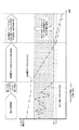
また、高容量型バッテリES−Eは、充電率(SOC:State of Charge)に対する容量劣化係数の変動が小さく、満充電電圧や放電終止電圧においても大幅に劣化することはない。一方、高出力型バッテリES−Pは、図2に示すように、SOCに対する容量劣化係数の変動が大きく、中間域のSOCにおける容量劣化係数は小さいが、中間域以外のSOCにおける容量劣化係数は大きい。したがって、容量劣化係数が所定値以下となるSOCの中間域が、高出力型バッテリES−Pの好適領域に設定される。なお、高出力型バッテリES−Pの中間域よりもSOCが低い領域と高い領域とでは、SOCが中間域から離れる際の容量劣化係数の増加率は高い領域の方が高い。 Further, the high capacity battery ES-E has a small variation in capacity deterioration coefficient with respect to the state of charge (SOC), and does not deteriorate significantly even at the full charge voltage or the end-of-discharge voltage. On the other hand, as shown in FIG. 2, the high-power battery ES-P has a large capacity deterioration coefficient with respect to the SOC and a small capacity deterioration coefficient in the intermediate SOC, but the capacity deterioration coefficient in the SOC other than the intermediate area is large. Therefore, an intermediate region of the SOC where the capacity deterioration coefficient is equal to or less than a predetermined value is set as a suitable region of the high-power battery ES-P. Note that, in the region where the SOC is lower and the region where the SOC is higher than the intermediate region of the high-power battery ES-P, the increase rate of the capacity deterioration coefficient when the SOC is away from the intermediate region is higher in the region.
VCU103は、高出力型バッテリES−Pの出力電圧を直流のまま昇圧する。また、VCU103は、電動車両の減速時にモータジェネレータ101が発電して直流に変換された電力を降圧する。さらに、VCU103は、高容量型バッテリES−Eの出力電圧を直流のまま降圧する。VCU103によって降圧された電力は、高出力型バッテリES−Pに充電される。なお、VCU103が出力する直流電力の電圧レベル又は電流レベルは、ECU115によって制御される。
The
PDU105は、直流電圧を交流電圧に変換して3相電流をモータジェネレータ101に供給する。また、PDU105は、モータジェネレータ101の回生動作時に入力される交流電圧を直流電圧に変換する。
電圧センサ107pは、高出力型バッテリES−Pの電圧Vpを検出する。電圧センサ107pが検出した電圧Vpを示す信号はECU115に送られる。電圧センサ107eは、高容量型バッテリES−Eの電圧Veを検出する。なお、電圧センサ107eが検出した電圧Veは、高出力型バッテリES−Pの電圧VpをVCU103が昇圧した値に等しい。電圧センサ107eが検出した電圧Veを示す信号はECU115に送られる。
The
電流センサ109pは、高出力型バッテリES−Pの入出力電流Ipを検出する。電流センサ109pが検出した入出力電流Ipを示す信号はECU115に送られる。電流センサ109eは、高容量型バッテリES−Eの入出力電流Ieを検出する。電流センサ109eが検出した入出力電流Ieを示す信号はECU115に送られる。
The
車速センサ111は、電動車両の走行速度(車速)VPを検出する。車速センサ111によって検出された車速VPを示す信号は、ECU115に送られる。
The
スイッチ部113は、高容量型バッテリES−EからPDU105又はVCU103までの電流経路を断接するコンタクタMCeと、高出力型バッテリES−PからVCU103までの電流経路を断接するコンタクタMCpとを有する。各コンタクタMCe,MCpは、ECU115の制御によって開閉される。
The
図3は、第1実施形態における高容量型バッテリES−E、高出力型バッテリES−P、VCU103、PDU105及びモータジェネレータ101の関係を示す電気回路図である。図3に示すように、VCU103は、高出力型バッテリES−Pの出力電圧を入力電圧として、ハイサイドとローサイドから成る2つのスイッチング素子をオンオフ切換動作することによって、高出力型バッテリES−Pの電圧を昇圧して出力する。また、これら2つのスイッチング素子をオンオフ切換動作せずに、上アーム(ハイサイド)のスイッチング素子をオン状態、下アーム(ローサイド)のスイッチング素子をオフ状態とすれば、高出力型バッテリES−Pは、高容量型バッテリES−E及びPDU105と電気系統的に直結された状態になる。また、PDU105は、高容量型バッテリES−Eの出力電圧を入力電圧として6つのスイッチング素子をオンオフ切換動作することによって、直流電圧を交流電圧に変換してモータジェネレータ101に出力する。これら6つのスイッチング素子をオンオフ切換動作せずに、全てのスイッチング素子をオフ状態とすれば、高容量型バッテリES−E及び高出力型バッテリES−Pは、モータジェネレータ101から電気系統的に開放された状態になる。
FIG. 3 is an electric circuit diagram showing a relationship among the high-capacity battery ES-E, the high-power battery ES-P, the
ECU115は、PDU105及びVCU103の制御、並びに、スイッチ部113の開閉制御を行う。また、ECU115には、電動車両のドライバによるアクセルペダル操作に応じたアクセルペダル開度(AP開度)を示す信号、車速センサ111からの車速VPを示す信号、電圧センサ107e,107pからの電圧Ve,Vpを示す信号、及び電流センサ109e,109pからの電流Ie,Ipを示す信号が入力される。
The
また、ECU115は、特性の異なる高容量型バッテリES−Eと高出力型バッテリES−Pの各々の特性を活かすよう、VCU103を用いた電力分配制御を行う。この電力分配制御を行えば、高容量型バッテリES−Eは、電動車両の加速走行時に一定の電力をモータジェネレータ101に電力を供給するよう用いられ、高出力型バッテリES−Pは、電動車両の走行のために大きな駆動力が必要なときに、モータジェネレータ101に電力を供給するよう用いられる。また、電動車両の減速走行時には、ECU115は、モータジェネレータ101が発電した回生電力によって、高出力型バッテリES−Pを優先的に充電する。回生電力による充電はCレートに換算すると高レートな充電に相当するので、本実施形態では、VCU103が機能しない場合を除き、高出力型バッテリES−Pが回生電力を受け入れ、高容量型バッテリES−Eは原則受け入れない。こういった電力分配制御が行われるため、高容量型バッテリES−EのSOCは、0%〜100%までの略全域が使用範囲として設定され、走行に伴い継続的に低下する。一方、高出力型バッテリES−PのSOCは、図2に示した例えば40%〜70%の中間域が好適に使用される領域(好適領域)として設定され、この好適領域に属する所定の中間値を維持するようその近傍で変動する。
Further, the
また、ECU115は、電圧センサ107p,107eが検出した各電圧及び電流センサ109p,109eが検出した各入出力電流に基づき、電流積算方式及び/又はOCV(開路電圧)推定方式によって、高容量型バッテリES−Eと高出力型バッテリES−Pの各SOCを導出する。また、ECU115は、AP開度及び車速VPに基づき、PDU105及びモータジェネレータ101によって構成される駆動部(以下、単に「駆動部」という。)の要求出力を算出する。ECU115は、駆動部の要求出力に応じた電流又は電圧が当該駆動部に供給されるよう、上記説明した電力分配制御を行う。
Further, the
さらに、ECU115は、電流センサ109eが検出した電流Ieや電圧センサ107eが検出した電圧Veに基づき、VCU103が機能しない状態を検知する。上述したように、ECU115は、駆動部の要求出力に応じた電流又は電圧が当該駆動部に供給されるよう、VCU103を用いて電力分配制御を行う。このとき、駆動部に対するVCU103の出力が目標値となるよう、ECU115はVCU103の2つのスイッチング素子を所望のデューティ比でオンオフ切換動作する。したがって、電流センサ109eが検出する電流Ie又は電圧センサ107eが検出する電圧Veは、上記目標値に応じた電流又は電圧に略等しくなる。この場合、ECU115は、VCU103が機能していると判断する。しかし、電流センサ109eが検出する電流Ie又は電圧センサ107eが検出する電圧Veが上記目標値に応じた電流又は電圧とは異なる場合、ECU115は、VCU103が機能していないと判断する。
Further, the
上述したVCU103が機能しない状態の検知は、電流センサ109eが検出した電流Ieや電圧センサ107eが検出した電圧Veに基づくものに限定されるものではない。例えば、電流センサ109eが検出した電流Ieや電圧センサ107eが検出した電圧Veに代えて、VCU103のスイッチング素子を監視したり、ECU115の状態を診断することで、当該状態を検知しても良い。
The detection of the state where the
なお、VCU103が機能しない状態とは、VCU103が故障した状態の他、ECU115がVCU103をオンオフ切換動作するためのスイッチング信号が送信されない又は当該スイッチング信号がVCU103に到達しない状態が含まれる。いずれの状態であっても、VCU103はECU115が所望する動作を行わない。なお、本実施形態では、VCU103の少なくとも上アーム(ハイサイド)のスイッチング素子が常時オフとなるオープン故障した状態が、VCU103が故障した状態である。すなわち、強制的な直結状態が継続する状態を指す。
The state in which the
以下、VCU103が機能しない状態が発生した際のECU115の制御について説明する。図4は、VCU103が機能しない状態が発生して第1実施形態のECU115が放電制御を行った場合の高容量型バッテリES−Eと高出力型バッテリES−Pの各電圧の経時変化を示す図である。また、図5及び図6は、VCU103が機能しない状態が発生した際に第1実施形態のECU115が行う処理の流れを示すフローチャートである。
Hereinafter, control of the
VCU103が機能する状態では、図4に示すように、ECU115はVCU103を用いた上述の電力分配制御を行っており、スイッチ部113の2つのコンタクタMCe,MCpはそれぞれ閉じられている。このとき、高容量型バッテリES−EのSOCは走行に伴い継続的に低下し、高出力型バッテリES−PのSOCは好適領域内の所定の中間値を維持するようその近傍で変動する。この状態で、VCU103が機能しない状態をECU115が検知すると(ステップS101でYES)、ECU115は、スイッチ部113における高容量型バッテリES−E側のコンタクタMCeを開く(ステップS103)。VCU103が機能しない状態でコンタクタMCeのみを開くと、図7に示すように、駆動部には高出力型バッテリES−Pのみから電力が供給される。なお、このときのVCU103は、上アーム(ハイサイド)のスイッチング素子がオン状態、下アーム(ローサイド)のスイッチング素子がオフ状態であるため、高出力型バッテリES−Pの出力電圧はそのまま駆動部に印加される。その結果、図4に示すように、高出力型バッテリES−PのSOCは電動車両の走行に従い低下し、高容量型バッテリES−EのSOCは変化しない。
In a state in which the
なお、VCU103が機能しないため高出力型バッテリES−Pのみが駆動部に電力を供給している状態で電動車両が減速する際、ECU115は、高容量型バッテリES−E側のコンタクタMCeを閉じても良い。VCU103が機能しない状態では、電動車両の減速時に得られた回生電力は、VCU103の上アーム(ハイサイド)のスイッチング素子の寄生ダイオードのために高出力型バッテリES−P側には供給されない。しかし、コンタクタMCeを閉じて駆動部と高容量型バッテリES−Eとの間の回路が閉じた状態であれば、高容量型バッテリES−Eが回生電力を受け入れる。
When the electric vehicle decelerates while only the high-power battery ES-P supplies power to the drive unit because the
次に、ECU115は、高出力型バッテリES−PのSOCを導出し(ステップS105)、このSOCが高出力型バッテリES−Pの好適領域の下限値Th1未満であるか否かを判断する(ステップS107)。高出力型バッテリES−PのSOCが下限値Th1未満であればステップS111に進むが、下限値Th1以上であればステップS109に進んで、高出力型バッテリES−Pのみが駆動部に電力を供給する形態を継続する。ステップS109を行った後は、ステップS105に戻る。
Next, the
図6に示すステップS111では、ECU115は、スイッチ部113における高容量型バッテリES−E側のコンタクタMCeを閉じて、高出力型バッテリES−P側のコンタクタMCpを開く。VCU103が機能しない状態でコンタクタMCpのみを開くと、図8に示すように、駆動部には高容量型バッテリES−Eのみから電力が供給される。その結果、図4に示すように、高容量型バッテリES−EのSOCは電動車両の走行に従い低下し、高出力型バッテリES−PのSOCは変化しない。なお、この状態で電動車両の減速時に得られた回生電力は、高容量型バッテリES−Eが受け入れる。
In step S111 shown in FIG. 6, the
次に、ECU115は、高容量型バッテリES−EのSOCを導出し(ステップS113)、このSOCが所定値Th2未満であるか否かを判断する(ステップS115)。高容量型バッテリES−EのSOCが所定値Th2未満であればステップS119に進むが、所定値Th2以上であればステップS117に進んで、高容量型バッテリES−Eのみが駆動部に電力を供給する形態を継続する。なお、所定値Th2は、電動車両が所定値以上の速度で走行可能な駆動力をモータジェネレータ101が出力するために、高容量型バッテリES−Eが供給すべき電力を出力可能なSOCの最低値である。
Next, the
ステップS119では、ECU115は、スイッチ部113における高出力型バッテリES−P側のコンタクタMCpを閉じる。VCU103が機能しない状態で高出力型バッテリES−PのSOCが好適領域の下限値Th1未満であり、高容量型バッテリES−EのSOCが所定値Th2未満であり、かつ、スイッチ部113のコンタクタMCe,MCpがそれぞれ閉じられると、図9に示すように、駆動部には高出力型バッテリES−P及び高容量型バッテリES−Eの双方が電力を供給可能な状態となる。その結果、図4に示すように、電動車両の走行に従い、高出力型バッテリES−PのSOC及び高容量型バッテリES−EのSOCの少なくとも一方が低下する。なお、この状態で電動車両の減速時に得られた回生電力は、高容量型バッテリES−Eが受け入れる。
In step S119, the
次に、ECU115は、高出力型バッテリES−P及び高容量型バッテリES−Eの各SOCを導出し(ステップS121)、少なくとも一方のバッテリのSOCが使用下限値まで低下したか否かを判断する(ステップS123)。少なくとも一方のSOCが使用下限値まで低下した場合はステップS127に進むが、双方のSOCが使用下限値以上であればステップS125に進んで、高出力型バッテリES−P及び高容量型バッテリES−Eの双方が電力を供給可能な形態を継続する。なお、使用下限値は、例えばSOC0%であり、バッテリ毎に異なっても良い。例えば、低SOCで劣化が進行しやすい高出力型バッテリES−Pの使用下限値はSOC10%であるのに対し、高容量型バッテリES−Eの使用下限値はSOC0%であっても良い。
Next, the
ステップS127では、ECU115は、スイッチ部113のコンタクタMCe,MCpの双方を開き、高出力型バッテリES−P及び高容量型バッテリES−Eの放電処理を禁止する。
In step S127, the
以上説明した例では、VCU103が機能しない状態において、スイッチ部113のコンタクタMCe,MCpを開いたり閉じたりする処理を行う基準として、各バッテリのSOCを用いているが、ECU115は、各バッテリの出力電圧を基準に上記処理を行っても良い。この場合、ステップS107で高出力型バッテリES−Pの出力電圧と比較される下限値Th1は、容量劣化係数が所定値以下となる電圧の好適領域の下限値である。また、ステップS115で高容量型バッテリES−Eの出力電圧と比較される所定値Th2は、電動車両が所定値以上の速度で走行可能な駆動力をモータジェネレータ101が出力するために、高容量型バッテリES−Eが供給すべき電力を出力可能な電圧の最低値である。また、ステップS123で高出力型バッテリES−P及び高容量型バッテリES−Eの各出力電圧と比較される使用下限値は、各バッテリの放電終止電圧である。
In the example described above, the SOC of each battery is used as a reference for performing the process of opening and closing the contactors MCe and MCp of the
以上説明したように、本実施形態では、高出力型バッテリES−Pの出力電圧を変換するVCU103が機能しない場合、高出力型バッテリES−PのSOCが好適領域の下限値Th1に低下するまでは、高出力型バッテリES−Pのみが駆動部に電力を供給する。このように、VCU103が機能しない状態となっても、高出力型バッテリES−Pと駆動部とを結ぶ経路を開くことはせずに、高出力型バッテリES−Pが駆動部に電力を供給することによって、電動車両の航続可能距離の減少を抑制できる。
As described above, in this embodiment, when the
なお、下限値Th1は、好適領域におけるSOCの最小値であるため、高出力型バッテリES−Pのみが駆動部に電力を供給する際に、高出力型バッテリES−Pの劣化を抑制しつつ、駆動部への電力供給を最大限に行える。 Since the lower limit value Th1 is the minimum SOC value in the preferred region, when only the high-power battery ES-P supplies power to the drive unit, the deterioration of the high-power battery ES-P is suppressed. The power supply to the drive unit can be maximized.
また、VCU103が機能しない状態において、高出力型バッテリES−PのSOCが下限値Th1未満であっても、高容量型バッテリES−EのSOCが所定値Th2に低下するまでは、高容量型バッテリES−Eのみが駆動部に電力を供給する。このように、VCU103が機能しない状態において、駆動部への電力供給を高出力型バッテリES−Pが行った後には、高容量型バッテリES−Eが当該電力供給を行うことによって、電動車両の航続可能距離の減少をさらに抑制できる。
Further, in a state where the
なお、所定値Th2は、電動車両が所定値以上の速度で走行可能な駆動力をモータジェネレータ101が出力するために、高容量型バッテリES−Eが供給すべき電力を出力可能なSOCの最低値であるため、高容量型バッテリES−Eからの駆動部への電力供給を最大限に行うことができる。その結果、電動車両は充分な距離を走行できる。
The predetermined value Th2 is the minimum SOC that can output the power to be supplied by the high-capacity battery ES-E in order for the
また、VCU103が機能しない状態において、高出力型バッテリES−PのSOCが下限値Th1未満であり、高容量型バッテリES−EのSOCが所定値Th2未満であっても、高出力型バッテリES−P及び高容量型バッテリES−Eの双方が駆動部に電力を供給可能である。このように、VCU103が機能しない状態において、駆動部への電力供給を高容量型バッテリES−Eが行った後には、高出力型バッテリES−P及び高容量型バッテリES−Eが可能な限り出力を駆動部に供給するため、電動車両の航続可能距離の減少を最大限に抑制できる。
Further, in a state where the
また、VCU103が機能する正常な状態では高容量型バッテリES−Eは回生電力を受け入れないため、高容量型バッテリES−Eの劣化を抑制できる。しかし、VCU103が機能しない状態では、駆動部が回生発電した電力を高容量型バッテリES−Eが受け入れるため、高容量型バッテリES−Eのみが駆動部に電力を供給する際の航続可能距離の減少を抑制できる。
Further, since the high capacity battery ES-E does not accept regenerative power in a normal state where the
このように、特性の異なる2つのバッテリを併用する電動車両において、一方のバッテリの出力電圧を変換するVCU103が機能しない状態であっても、双方のバッテリの電力を使用できるため、電動車両の航続可能距離の減少を最大限に抑制できる。
Thus, in an electric vehicle that uses two batteries having different characteristics in combination, the power of both batteries can be used even when the
なお、本実施形態のVCU101は、高出力型バッテリES−Pの電圧Vpを昇圧するが、高容量型バッテリES−Eの電圧Veが高出力型バッテリES−Pの電圧Vpよりも低い場合、高出力型バッテリES−Pの電圧Vpを降圧するVCUが用いられる。また、双方向に昇降圧が可能なVCUを用いても良い。また、図10及び図11に示すように、高容量型バッテリES−Eの出力電圧を直流のまま変換する、VCU103と同様のVCU203を設けても良い。2つのVCUを設けることで、駆動部に印加される電圧が高容量型バッテリES−Eに束縛されないため、効率が向上する。
Note that the
(第2実施形態)
図10は、第2実施形態の電動車両の内部構成を示すブロック図である。また、図11は、第2実施形態における高容量型バッテリ、高出力型バッテリ、VCU、PDU及びモータジェネレータの関係を示す電気回路図である。第2実施形態の電動車両が第1実施形態の電動車両と異なる点は、高容量型バッテリES−Eの電圧を変換するVCU203及び電圧センサ107が設けられたことである。この点以外は第1実施形態と同様であり、図10及び図11に示された構成要素に関して、第1実施形態と同一又は同等部分には同一符号又は相当符号を付して説明を簡略化又は省略する。
(Second Embodiment)
FIG. 10 is a block diagram illustrating an internal configuration of the electric vehicle according to the second embodiment. FIG. 11 is an electric circuit diagram showing the relationship among the high-capacity battery, high-power battery, VCU, PDU, and motor generator in the second embodiment. The difference between the electric vehicle of the second embodiment and the electric vehicle of the first embodiment is that a
VCU203は、高容量型バッテリES−Eの出力電圧を直流のまま降圧する。また、VCU203は、VCU103が機能しない場合に、電動車両の減速時にモータジェネレータ101が発電して直流に変換された電力を昇圧する。さらに、VCU203は、PDU105及びモータジェネレータ101によって構成される駆動部(以下、単に「駆動部」という。)が駆動していない状態であれば、VCU103の出力電圧を直流のまま昇圧可能である。VCU203によって昇圧された電力は、高容量型バッテリES−Eに充電される。図11に示すように、VCU203は、高容量型バッテリES−Eの出力電圧を入力電圧として、ハイサイドとローサイドから成る2つのスイッチング素子をオンオフ切換動作することによって、高容量型バッテリES−Eの電圧を降圧して出力する。
The
電圧センサ107は、VCU103,203の出力電圧であって、駆動部に印加される電圧を検出する。電圧センサ107が検出した電圧を示す信号はECU1152に送られる。
The
本実施形態のECU1152は、PDU105及びVCU103,203の制御、並びに、スイッチ部113の開閉制御を行う。また、ECU1152は、第1実施形態のECU115と同様に、高容量型バッテリES−Eと高出力型バッテリES−Pの各SOCの導出及び駆動部の要求出力の算出の判別を行う。また、ECU1152は、VCU103,203を用いた第1実施形態と同様の電力分配制御を行う。
The
2つのVCU103,203を用いて電力分配制御を行う場合、継続的に放電する高容量型バッテリES−EのVCU203は、目標電圧を出力するための電圧制御モードによる制御が好ましい。一方、駆動部の要求出力に応じて充放電を頻繁に切替える高出力型バッテリES−PのVCU103は、目標電流を出力するための電流制御モードによる制御が好ましい。従って、ECU1152は、電流センサ109pが検出した電流Ipなどに基づき、VCU103が機能しない状態を検知する。
When performing power distribution control using the two
さらに、ECU1152は、電圧センサ107が検出した電圧などに基づき、VCU203が機能しない状態を検知する。上述したように、ECU1152は、駆動部の要求出力に応じた電流又は電圧が当該駆動部に供給されるよう、VCU103,203を用いて電力分配制御を行う。このとき、駆動部に対するVCU103,203の出力が目標値となるよう、ECU1152はVCU103,203をそれぞれ所望のデューティ比でオンオフ切換動作する。したがって、電圧センサ107が検出する電圧は、上記目標値に応じた電圧に略等しくなる。そして、電流センサ109pが検出する電流は、上記目標値に応じた電流に略等しくなる。この場合、ECU1152は、VCU103,203が機能していると判断する。しかし、電流センサ109pが検出する電流Ipが上記目標値に応じた電流とは異なる場合、ECU1152は、VCU103が機能していないと判断する。
Further, the
上述したVCU103,203が機能しない状態の検知は、電流センサ109pが検出した電流Ipや電圧センサ107が検出した電圧に基づくものに限定されるものではない。例えば、電流センサ109pが検出した電流Ipや電圧センサ107が検出した電圧に代えて、VCU103,203のスイッチング素子を監視したり、ECU1152の状態を診断することで、当該状態を検知しても良い。
The detection of the state where the
なお、VCU103が機能しない状態とは、第1実施形態と同様に、VCU103が故障した状態の他、ECU1152がVCU103をオンオフ切換動作するためのスイッチング信号が送信されない又は当該スイッチング信号がVCU103に到達しない状態が含まれる。いずれの状態であっても、VCU103はECU1152が所望する動作を行わない。なお、本実施形態では、VCU103の少なくとも上アーム(ハイサイド)のスイッチング素子が常時オフとなるオープン故障した状態が、VCU103が故障した状態である。すなわち、強制的な直結状態が継続する状態を指す。
Note that the state in which the
以下、VCU103が機能しない状態が発生した際のECU1152の制御について説明する。図12は、VCU103が機能しない状態が発生して第2実施形態のECU1152が放電制御を行った場合の高容量型バッテリES−Eと高出力型バッテリES−Pの各電圧の経時変化を示す図である。また、図13は、VCU103が機能しない状態が発生した際に第2実施形態のECU1152が行う処理の流れを示すフローチャートである。なお、図13に示されたステップに関して、第1実施形態と同一又は同等部分には同一符号又は相当符号を付して説明を簡略化又は省略する。
Hereinafter, the control of the
VCU103が機能する状態では、図12に示すように、ECU1152はVCU103,203を用いた電力分配制御を行っており、スイッチ部113の2つのコンタクタMCe,MCpはそれぞれ閉じられている。このとき、高容量型バッテリES−EのSOCは走行に伴い継続的に低下し、高出力型バッテリES−PのSOCは好適領域内の所定の中間値を維持するようその近傍で変動する。この状態で、VCU103が機能しない状態をECU1152が検知すると(ステップS101でYES)、ECU1152は、スイッチ部113における高容量型バッテリES−E側のコンタクタMCeを開く(ステップS103)。
In a state in which the
次に、ECU1152は、高出力型バッテリES−P及び高容量型バッテリES−Eの各SOCを導出し(ステップS205)、高出力型バッテリES−PのSOCが好適領域の下限値Th1未満であるか否かを判断する(ステップS107)。高出力型バッテリES−PのSOCが下限値Th1未満であればステップS111に進み、下限値Th1以上であればステップS221に進む。
Next, the
ステップS221では、ECU1152は、モータジェネレータ101が停止状態であれば、または、モータジェネレータ101に給電されていない状態であれば、高出力型バッテリES−P及び高容量型バッテリES−Eの各電圧及びVCU203が動作可能な電圧変換率に基づき、高出力型バッテリES−Pから高容量型バッテリES−Eに電力を移行可能か否かを判断する。すなわち、ECU1152は、図11に示すように高容量型バッテリES−Eから見たVCU203が降圧型ならば、高出力型バッテリES−Pの電圧をVCU203によって昇圧し、高容量型バッテリES−Eに入力できる。従って、ECU1152は、高出力型バッテリES−Pの電圧をVCU203が動作可能な最も高い変換率で変換した値が、高容量型バッテリES−Eの電圧よりも高ければ、高出力型バッテリES−Pから高容量型バッテリES−Eへの電力移行が可能と判断する。
In step S221, if the
なお、VCU203は前述した降圧型のみならず、昇圧型や昇降圧型であっても良い。VCU203が昇圧型の場合、ECU1152は、高出力型バッテリES−Pの電圧が、高容量型バッテリES−Eの電圧よりも高ければ、高出力型バッテリES−Pから高容量型バッテリES−Eへの電力移行が可能と判断する。
The
ステップS221において電力移行が可能と判断されるとステップS223に進み、電力移行が不可能と判断されるとステップS109に進む。ステップS223では、ECU1152は、高容量型バッテリES−E側のコンタクタMCeを閉じる。次に、ECU1152は、図14に示すように、高出力型バッテリES−Pから高容量型バッテリES−Eに電力が移行するようVCU203を制御する(ステップS225)。その結果、図12に示すように、高出力型バッテリES−PのSOCは低下し、高容量型バッテリES−EのSOCは増加する。次に、ECU1152は、高容量型バッテリES−E側のコンタクタMCeを開く(ステップS227)。
If it is determined in step S221 that power transfer is possible, the process proceeds to step S223. If it is determined that power transfer is not possible, the process proceeds to step S109. In step S223, the
一方、ステップS109では、ECU1152は、高出力型バッテリES−Pのみから駆動部に電力を供給する図15に示す形態を継続する。その結果、図12に示すように、高出力型バッテリES−PのSOCは電動車両の走行に従い低下し、高容量型バッテリES−EのSOCは変化しない。なお、この状態で電動車両の減速時に得られた回生電力は、VCU203によってその電圧などが調整され高容量型バッテリES−Eが受け入れる。ステップS109又は上述したステップS227を行った後は、ステップS205に戻る。
On the other hand, in step S109, the
ステップS111以降の処理は、第1実施形態の図6で説明した処理と同様である。すなわち、VCU103が機能しない状態でコンタクタMCpのみを開くと、図16に示すように、駆動部には高容量型バッテリES−Eのみから電力が供給される。その結果、図12に示すように、高容量型バッテリES−EのSOCは電動車両の走行に従い低下し、高出力型バッテリES−PのSOCは変化しない。その後、高容量型バッテリES−EのSOCが所定値Th2まで低下すると、スイッチ部113のコンタクタMCe,MCpがそれぞれ閉じられ、図17に示すように、駆動部には高出力型バッテリES−P及び高容量型バッテリES−Eの双方が電力を供給可能な状態となる。その結果、図12に示すように、電動車両の走行に従い、高出力型バッテリES−PのSOC及び高容量型バッテリES−EのSOCの少なくとも一方が低下する。なお、図17に示す形態では、VCU203が高容量型バッテリES−Eの出力電圧を高出力型バッテリES−Pの出力電圧と同レベルに変換することによって、高出力型バッテリES−P及び高容量型バッテリES−Eの双方が駆動部に電力を供給する。
The processing after step S111 is the same as the processing described in FIG. 6 of the first embodiment. That is, when only the contactor MCp is opened in a state where the
本実施形態で説明した例でも、VCU103が機能しない状態において、スイッチ部113のコンタクタMCe,MCpを開いたり閉じたりする処理を行う基準として、各バッテリのSOCを用いているが、ECU1152は、各バッテリの出力電圧を基準に上記処理を行っても良い。この場合、ステップS107で高出力型バッテリES−Pの出力電圧と比較される下限値Th1は、容量劣化係数が所定値以下となる電圧の好適領域の下限値である。また、ステップS115で高容量型バッテリES−Eの出力電圧と比較される所定値Th2は、電動車両が所定値以上の速度で走行可能な駆動力をモータジェネレータ101が出力するために、高容量型バッテリES−Eが供給すべき電力を出力可能な電圧の最低値である。また、ステップS123で高出力型バッテリES−P及び高容量型バッテリES−Eの各出力電圧と比較される使用下限値は、各バッテリの放電終止電圧である。
Even in the example described in the present embodiment, the SOC of each battery is used as a reference for performing the process of opening and closing the contactors MCe and MCp of the
また、本実施形態では、ECU1152は、VCU103が機能しない状態を検知するが、VCU203が機能しない状態を検知しても良い。VCU203が機能しない状態をECU1152が検知した場合であっても、高出力型バッテリES−PのSOCが好適範囲の下限値Th1に低下するまで、高容量型バッテリES−Eへの電力移行又は高出力型バッテリES−Pのみが駆動部に電力を供給する形態を実行し、高容量型バッテリES−Eのみが駆動部に電力を供給する形態を実行する。
In this embodiment, the
以上説明したように、本実施形態では、高出力型バッテリES−Pの出力電圧を変換するVCU103が機能しない場合、高出力型バッテリES−PのSOCが好適領域の下限値Th1に低下するまでは、高出力型バッテリES−Pのみが駆動部に電力を供給するか、高出力型バッテリES−Pから高容量型バッテリES−Eへの電力移行を行う。このように、VCU103が機能しない状態となっても高出力型バッテリES−Pの電力は有効に利用され、高出力型バッテリES−Pのみの電力供給を行えば高出力型バッテリES−Pが駆動部に電力を供給する際の電動車両の航続可能距離の減少を抑制でき、電力移行を行えば高容量型バッテリES−Eが駆動部に電力を供給する際の電動車両の航続可能距離の減少を抑制できる。特に電力移行を行った電力は電圧と電流が制御不能な状態から、制御可能な状態に戻るため、その制御性が格別に向上する。
As described above, in this embodiment, when the
なお、下限値Th1は、好適領域におけるSOCの最小値であるため、高出力型バッテリES−Pのみが駆動部に電力を供給する際に、高出力型バッテリES−Pの劣化を抑制しつつ、駆動部への電力供給を最大限に行える。 Since the lower limit value Th1 is the minimum SOC value in the preferred region, when only the high-power battery ES-P supplies power to the drive unit, the deterioration of the high-power battery ES-P is suppressed. The power supply to the drive unit can be maximized.
また、高出力型バッテリES−Pのみの電力供給及び電力移行の双方が実行可能であれば電力移行が優先して行われる。駆動部に印加される電圧は調整可能である方が良く、高容量型バッテリES−Eからの電力供給であればVCU203によって電圧変換されるため、電力移行によって高出力型バッテリES−Pの電力を高容量型バッテリES−Eに移した方が、高出力型バッテリES−Pのみの電力供給を行うよりも好ましい。
In addition, if both power supply and power transfer of only the high-power battery ES-P can be performed, the power transfer is performed with priority. It is better that the voltage applied to the drive unit is adjustable, and if power is supplied from the high-capacity battery ES-E, the voltage is converted by the
また、電力移行の実行可否は、高出力型バッテリES−P及び高容量型バッテリES−Eの各電圧及びVCU203が動作可能な電圧変換率に基づき判定され、高出力型バッテリES−Pの電圧が、高容量型バッテリES−Eの電圧よりも高ければ、電力移行が実行可能と判定する。したがって、電力移行は、高出力型バッテリES−Pから高容量型バッテリES−Eへの電力移行が可能な場合に限って行われる。
Further, whether or not to execute power transfer is determined based on each voltage of the high-power battery ES-P and the high-capacity battery ES-E and a voltage conversion rate at which the
また、VCU103が機能しない状態において、高出力型バッテリES−PのSOCが下限値Th1未満であっても、高容量型バッテリES−EのSOCが所定値Th2に低下するまでは、高容量型バッテリES−Eのみが駆動部に電力を供給する。このように、VCU103が機能しない状態において、駆動部への電力供給を高出力型バッテリES−Pが行った後には、高容量型バッテリES−Eが当該電力供給を行うことによって、電動車両の航続可能距離の減少をさらに抑制できる。
Further, in a state where the
なお、所定値Th2は、電動車両が所定値以上の速度で走行可能な駆動力をモータジェネレータ101が出力するために、高容量型バッテリES−Eが供給すべき電力を出力可能なSOCの最低値であるため、高容量型バッテリES−Eからの駆動部への電力供給を最大限に行うことができる。その結果、電動車両は充分な距離を走行できる。
The predetermined value Th2 is the minimum SOC that can output the power to be supplied by the high-capacity battery ES-E in order for the
また、VCU103が機能しない状態において、高出力型バッテリES−PのSOCが下限値Th1未満であり、高容量型バッテリES−EのSOCが所定値Th2未満であっても、高出力型バッテリES−P及び高容量型バッテリES−Eの双方が駆動部に電力を供給可能である。このように、VCU103が機能しない状態において、駆動部への電力供給を高容量型バッテリES−Eが行った後には、高出力型バッテリES−P及び高容量型バッテリES−Eが可能な限り出力を駆動部に供給するため、電動車両の航続可能距離の減少を最大限に抑制できる。
Further, in a state where the
また、VCU103が機能しない状態において、高出力型バッテリES−PのSOCが下限値Th1未満であり、高容量型バッテリES−EのSOCが所定値Th2未満であっても、VCU203が高容量型バッテリES−Eの出力電圧を高出力型バッテリES−Pの出力電圧と同レベルに変換することによって、高出力型バッテリES−P及び高容量型バッテリES−Eの双方が駆動部に電力を供給する。このように、VCU103が機能しない状態において、駆動部への電力供給を高容量型バッテリES−Eが行った後には、高出力型バッテリES−P及び高容量型バッテリES−Eが可能な限り出力を駆動部に供給するため、電動車両の航続可能距離の減少を最大限に抑制できる。
Further, in a state where the
また、VCU103が機能する正常な状態では高容量型バッテリES−Eは回生電力を受け入れないため、高容量型バッテリES−Eの劣化を抑制できる。しかし、VCU103が機能しない状態では、駆動部が回生発電した電力を高容量型バッテリES−Eが受け入れるため、高容量型バッテリES−Eのみが駆動部に電力を供給する際の航続可能距離の減少を抑制できる。
Further, since the high capacity battery ES-E does not accept regenerative power in a normal state where the
このように、特性の異なる2つのバッテリを併用する電動車両において、一方のバッテリの出力電圧を変換するVCUが機能しない状態であっても、双方のバッテリの電力を使用できるため、電動車両の航続可能距離の減少を最大限に抑制できる。 Thus, in an electric vehicle that uses two batteries having different characteristics in combination, the power of both batteries can be used even if the VCU that converts the output voltage of one battery does not function. The reduction in possible distance can be suppressed to the maximum.
なお、本発明は、前述した実施形態に限定されるものではなく、適宜、変形、改良、等が可能である。例えば、上記説明した電動車両は、1MOT型のEV(Electrical Vehicle)であるが、複数のモータジェネレータを搭載したEVであっても、少なくとも1つのモータジェネレータと共に内燃機関を搭載したHEV(Hybrid Electrical Vehicle)やPHEV(Plug-in Hybrid Electrical Vehicle)であっても、FCV(Fuel Cell Vehicle)であっても良い。 In addition, this invention is not limited to embodiment mentioned above, A deformation | transformation, improvement, etc. are possible suitably. For example, although the electric vehicle described above is a 1MOT type EV (Electrical Vehicle), even an EV equipped with a plurality of motor generators is an HEV (Hybrid Electrical Vehicle) equipped with an internal combustion engine together with at least one motor generator. ), PHEV (Plug-in Hybrid Electrical Vehicle), or FCV (Fuel Cell Vehicle).
101 モータジェネレータ(MG)
103,203 VCU
105 PDU
107p,107e,107 電圧センサ
109p,109e 電流センサ
111 車速センサ
113 スイッチ部
115,1152 ECU
ES−E 高容量型バッテリ
ES−P 高出力型バッテリ
MCe,MCp コンタクタ
101 Motor generator (MG)
103,203 VCU
105 PDU
107p, 107e, 107
ES-E High-capacity battery ES-P High-power battery MCe, MCp Contactor
Claims (14)
第2蓄電器と、
前記第1蓄電器及び前記第2蓄電器の少なくとも一方から供給される電力により駆動する駆動部と、
前記第1蓄電器の出力電圧を変換する第1変換部及び前記第2蓄電器の出力電圧を変換する第2変換部を含み、前記第1蓄電器と前記第2蓄電器と前記駆動部の間の電流経路を構成する充放電回路と、
前記第1蓄電器の充電率又は出力電圧である第1変数を検出する第1検出部と、
前記第1変換部が機能しない状態を検知する検知部と、
前記充放電回路を介した前記第1蓄電器と前記第2蓄電器と前記駆動部の間の充放電を制御する制御部と、を備えた駆動装置であって、
前記制御部は、
前記第1変数と前記第1蓄電器の劣化因子との関係に基づき、前記検知部が前記状態を検知した場合は、前記劣化因子がしきい値以下となる好適領域内の第1所定値に前記第1変数が低下するまで、前記第1蓄電器のみが前記駆動部に電力を供給する第1制御及び前記第1蓄電器の電力を前記第2蓄電器に移す第2制御のいずれか一方を行うよう前記充放電回路を制御する、駆動装置。 A first capacitor;
A second battery,
A drive unit driven by power supplied from at least one of the first capacitor and the second capacitor;
A current path between the first capacitor, the second capacitor, and the drive unit, the first converter including a first converter that converts the output voltage of the first capacitor and a second converter that converts the output voltage of the second capacitor; A charge / discharge circuit comprising:
A first detector that detects a first variable that is a charging rate or an output voltage of the first capacitor;
A detection unit for detecting a state in which the first conversion unit does not function;
A control unit that controls charging / discharging between the first capacitor, the second capacitor, and the driving unit via the charging / discharging circuit,
The controller is
Based on the relationship between the first variable and the deterioration factor of the first capacitor, when the detection unit detects the state, the deterioration factor is set to a first predetermined value within a suitable region that is equal to or less than a threshold value. Until the first variable is decreased, the first control is performed so that only the first capacitor supplies power to the driving unit, and the second control transfers the power of the first capacitor to the second capacitor. A drive device that controls a charge / discharge circuit.
前記制御部は、前記検知部が前記状態を検知した場合、
前記第1制御の実行可否及び前記第2制御の実行可否を判定し、
前記第1制御及び前記第2制御の双方が実行可能であれば、前記第1制御より前記第2制御を優先して行うよう前記充放電回路を制御する、駆動装置。 The drive device according to claim 1,
When the detection unit detects the state, the control unit,
Determining whether the first control is executable and whether the second control is executable;
If both the first control and the second control are executable, the drive device controls the charge / discharge circuit so that the second control is performed with priority over the first control.
前記第2蓄電器の充電率又は出力電圧である第2変数を検出する第2検出部を備え、
前記制御部は、前記第2制御の実行可否を、前記第1変数、前記第2変数及び前記第2変換部の変換率に基づき判定する、駆動装置。 The drive device according to claim 2,
A second detector that detects a second variable that is a charging rate or an output voltage of the second battery;
The control unit determines whether or not the second control can be executed based on the first variable, the second variable, and a conversion rate of the second conversion unit.
前記制御部は、
前記第2変換部が前記第2蓄電器の出力電圧に対する昇圧と降圧のうち昇圧が可能な場合は、前記第1変数に応じた前記第1蓄電器の出力電圧が、前記第2変数に応じた前記第2蓄電器の出力電圧よりも高ければ、前記第2制御が実行可能と判定し、
前記第2変換部が前記第2蓄電器の出力電圧に対する昇圧と降圧のうち降圧が可能な場合は、前記第1変数に応じた前記第1蓄電器の出力電圧を前記第2変換部の最大の変換率で変換した値が、前記第2変数に応じた前記第2蓄電器の出力電圧よりも高ければ、前記第2制御が実行可能と判定する、駆動装置。 The drive device according to claim 3,
The controller is
When the second conversion unit is capable of boosting or stepping down the output voltage of the second capacitor, the output voltage of the first capacitor corresponding to the first variable is determined according to the second variable. If it is higher than the output voltage of the second battery, it is determined that the second control is executable,
When the second converter is capable of stepping down between stepping up and stepping down the output voltage of the second capacitor, the maximum conversion of the second converter is performed by converting the output voltage of the first capacitor according to the first variable. The drive device that determines that the second control is executable if the value converted by the rate is higher than the output voltage of the second battery according to the second variable.
前記第2蓄電器の充電率又は出力電圧である第2変数を検出する第2検出部を備え、
前記制御部は、前記検知部が前記状態を検知した場合、前記第1変数が前記第1所定値未満であれば、前記第2変数が第2所定値に低下するまで、前記第2蓄電器のみが前記駆動部に電力を供給するよう前記充放電回路を制御する、駆動装置。 The drive device according to any one of claims 1 to 4,
A second detector that detects a second variable that is a charging rate or an output voltage of the second battery;
When the detection unit detects the state, if the first variable is less than the first predetermined value, the control unit detects only the second capacitor until the second variable decreases to a second predetermined value. Controls the charge / discharge circuit to supply power to the drive unit.
前記第2所定値は、前記駆動部が所定値以上の駆動力を出力可能な前記第2変数の最低値である、駆動装置。 The drive device according to claim 5,
The second predetermined value is a driving device in which the driving unit is a minimum value of the second variable that can output a driving force equal to or greater than a predetermined value.
前記制御部は、前記検知部が前記状態を検知した場合、前記第1変数が前記第1所定値未満、かつ、前記第2変数が前記第2所定値未満であれば、前記第1蓄電器及び前記第2蓄電器の双方が前記駆動部に電力を供給可能であるよう前記充放電回路を制御する、駆動装置。 The drive device according to claim 5 or 6,
The control unit, when the detection unit detects the state, if the first variable is less than the first predetermined value and the second variable is less than the second predetermined value, the first capacitor and A drive device that controls the charge / discharge circuit so that both of the second capacitors can supply power to the drive unit.
前記制御部は、前記検知部が前記状態を検知した場合、前記第1変数が前記第1所定値未満、かつ、前記第2変数が前記第2所定値未満であれば、前記第2変換部が、前記第2蓄電器の出力電圧を、前記第1蓄電器の出力電圧と同レベルに変換し、前記第1蓄電器及び前記第2蓄電器の双方が前記駆動部に電力を供給するよう前記充放電回路を制御する、駆動装置。 The drive device according to claim 5 or 6,
The control unit, when the detection unit detects the state, if the first variable is less than the first predetermined value and the second variable is less than the second predetermined value, the second conversion unit. The charge / discharge circuit converts the output voltage of the second capacitor to the same level as the output voltage of the first capacitor, and supplies power to the drive unit from both the first capacitor and the second capacitor. Controlling the driving device.
前記制御部は、前記検知部が前記状態を検知した場合、前記第2蓄電器における前記駆動部が回生発電した電力の受け入れ量を、前記検知部が前記状態を検知しない場合に比べて増大するよう前記充放電回路を制御する、駆動装置。 The drive device according to any one of claims 1 to 8,
When the detection unit detects the state, the control unit increases the acceptance amount of the electric power regenerated by the drive unit in the second battery compared to the case where the detection unit does not detect the state. A drive device for controlling the charge / discharge circuit.
前記制御部は、前記検知部が前記状態を検知しない場合、前記駆動部が回生発電した電力を前記第2蓄電器が受け入れないよう前記充放電回路を制御する、駆動装置。 The drive device according to claim 9,
The said control part is a drive device which controls the said charging / discharging circuit so that the said 2nd electrical storage device will not accept the electric power which the said drive part regenerated-generated, when the said detection part does not detect the said state.
前記第1所定値は、前記好適領域における前記第1変数の最小値である、駆動装置。 The drive device according to any one of claims 1 to 10,
The driving device, wherein the first predetermined value is a minimum value of the first variable in the preferred region.
前記第1蓄電器は、前記第2蓄電器に比べて、出力重量密度が優れ、かつ、エネルギー重量密度が劣る、駆動装置。 The drive device according to any one of claims 1 to 11,
The first power storage device has a higher output weight density and a lower energy weight density than the second power storage device.
第2蓄電器と、
前記第1蓄電器及び前記第2蓄電器の少なくとも一方から供給される電力により駆動する駆動部と、
前記第1蓄電器の出力電圧を変換する第1変換部及び前記第2蓄電器の出力電圧を変換する第2変換部を含み、前記第1蓄電器と前記第2蓄電器と前記駆動部の間の電流経路を構成する充放電回路と、
前記第1蓄電器の充電率又は出力電圧である第1変数を検出する第1検出部と、
前記第1変換部が機能しない状態を検知する検知部と、
前記充放電回路を介した前記第1蓄電器と前記第2蓄電器と前記駆動部の間の充放電を制御する制御部と、を備えた駆動装置が行う制御方法であって、
前記制御部は、
前記第1変数と前記第1蓄電器の劣化因子との関係に基づき、前記検知部が前記状態を検知した場合は、前記劣化因子がしきい値以下となる好適領域内の第1所定値に前記第1変数が低下するまで、前記第1蓄電器のみが前記駆動部に電力を供給する第1制御及び前記第1蓄電器の電力を前記第2蓄電器に移す第2制御のいずれか一方を行うよう前記充放電回路を制御する、制御方法。 A first capacitor;
A second battery,
A drive unit driven by power supplied from at least one of the first capacitor and the second capacitor;
A current path between the first capacitor, the second capacitor, and the drive unit, the first converter including a first converter that converts the output voltage of the first capacitor and a second converter that converts the output voltage of the second capacitor. A charge / discharge circuit comprising:
A first detector that detects a first variable that is a charging rate or an output voltage of the first capacitor;
A detection unit for detecting a state in which the first conversion unit does not function;
A control method performed by a driving device comprising: a control unit that controls charging / discharging between the first capacitor, the second capacitor, and the driving unit via the charging / discharging circuit,
The controller is
Based on the relationship between the first variable and the deterioration factor of the first capacitor, when the detection unit detects the state, the deterioration factor is set to a first predetermined value within a suitable region that is equal to or less than a threshold value. Until the first variable is decreased, the first control is performed so that only the first capacitor supplies power to the driving unit, and the second control transfers the power of the first capacitor to the second capacitor. A control method for controlling a charge / discharge circuit.
Priority Applications (1)
| Application Number | Priority Date | Filing Date | Title |
|---|---|---|---|
| JP2016050986A JP6600586B2 (en) | 2016-03-15 | 2016-03-15 | DRIVE DEVICE, TRANSPORTATION DEVICE, AND CONTROL METHOD |
Applications Claiming Priority (1)
| Application Number | Priority Date | Filing Date | Title |
|---|---|---|---|
| JP2016050986A JP6600586B2 (en) | 2016-03-15 | 2016-03-15 | DRIVE DEVICE, TRANSPORTATION DEVICE, AND CONTROL METHOD |
Publications (2)
| Publication Number | Publication Date |
|---|---|
| JP2017169311A JP2017169311A (en) | 2017-09-21 |
| JP6600586B2 true JP6600586B2 (en) | 2019-10-30 |
Family
ID=59914120
Family Applications (1)
| Application Number | Title | Priority Date | Filing Date |
|---|---|---|---|
| JP2016050986A Active JP6600586B2 (en) | 2016-03-15 | 2016-03-15 | DRIVE DEVICE, TRANSPORTATION DEVICE, AND CONTROL METHOD |
Country Status (1)
| Country | Link |
|---|---|
| JP (1) | JP6600586B2 (en) |
Families Citing this family (10)
| Publication number | Priority date | Publication date | Assignee | Title |
|---|---|---|---|---|
| CN108909490B (en) * | 2018-07-06 | 2021-01-26 | 北京新能源汽车股份有限公司 | Vehicle charging and discharging control method and device, charging and discharging system and vehicle |
| JP7039513B2 (en) | 2019-03-14 | 2022-03-22 | 本田技研工業株式会社 | Power system |
| JP7069075B2 (en) | 2019-03-26 | 2022-05-17 | 本田技研工業株式会社 | Power system |
| JP7039520B2 (en) | 2019-05-28 | 2022-03-22 | 本田技研工業株式会社 | Power system |
| JP7041095B2 (en) | 2019-05-28 | 2022-03-23 | 本田技研工業株式会社 | Power system |
| JP7096203B2 (en) * | 2019-06-06 | 2022-07-05 | 本田技研工業株式会社 | Power system |
| CN114303319A (en) * | 2019-09-02 | 2022-04-08 | 罗姆股份有限公司 | Switch driving circuit |
| JP2022144890A (en) | 2021-03-19 | 2022-10-03 | 本田技研工業株式会社 | Power supply system |
| JP2022145064A (en) | 2021-03-19 | 2022-10-03 | 本田技研工業株式会社 | Power supply system |
| JP2022144986A (en) | 2021-03-19 | 2022-10-03 | 本田技研工業株式会社 | Power supply system of moving body |
Family Cites Families (2)
| Publication number | Priority date | Publication date | Assignee | Title |
|---|---|---|---|---|
| JP5227230B2 (en) * | 2009-03-24 | 2013-07-03 | トヨタ自動車株式会社 | Electric vehicle |
| JP2014147197A (en) * | 2013-01-29 | 2014-08-14 | Hitachi Automotive Systems Ltd | Battery control device |
-
2016
- 2016-03-15 JP JP2016050986A patent/JP6600586B2/en active Active
Also Published As
| Publication number | Publication date |
|---|---|
| JP2017169311A (en) | 2017-09-21 |
Similar Documents
| Publication | Publication Date | Title |
|---|---|---|
| JP6600586B2 (en) | DRIVE DEVICE, TRANSPORTATION DEVICE, AND CONTROL METHOD | |
| JP5605436B2 (en) | Electric vehicle and control method thereof | |
| US8594873B2 (en) | Power supply system for electric powered vehicle and control method thereof | |
| JP6343599B2 (en) | Drive device | |
| EP2428388A1 (en) | Power supply system and vehicle equipped with power supply system | |
| JP6214609B2 (en) | Drive device | |
| WO2014115209A1 (en) | Power supply system for vehicle | |
| JP6412847B2 (en) | Power storage device and control method | |
| US10439405B2 (en) | Power storage apparatus, transport device, and control method | |
| US10158246B2 (en) | Energy storage device, transport apparatus, and control method | |
| JP5949436B2 (en) | Vehicle, power supply system, and control method for power supply system | |
| JP6194344B2 (en) | Driving device and transportation equipment | |
| US11485234B2 (en) | Power supply system | |
| JP2017085754A (en) | Power storage device, transportation device, and control method | |
| JP6713283B2 (en) | Power storage device, transportation device, and control method | |
| JP6336953B2 (en) | DRIVE DEVICE, TRANSPORTATION DEVICE, AND CONTROL METHOD | |
| JP6170984B2 (en) | Power storage device, transport device and control method | |
| JP6600587B2 (en) | DRIVE DEVICE, TRANSPORTATION DEVICE, AND CONTROL METHOD | |
| JP6364396B2 (en) | Power storage device, transport device and control method | |
| JP6492001B2 (en) | DRIVE DEVICE, TRANSPORTATION DEVICE, AND CONTROL METHOD | |
| JP6335860B2 (en) | DRIVE DEVICE, ITS CONTROL METHOD, AND TRANSPORTATION DEVICE | |
| US9731620B2 (en) | Drive device, energy storage control method for drive device, and transport apparatus | |
| JP6713284B2 (en) | Drive device, transportation device and control method | |
| JP2017065284A (en) | Hybrid vehicle |
Legal Events
| Date | Code | Title | Description |
|---|---|---|---|
| RD02 | Notification of acceptance of power of attorney |
Free format text: JAPANESE INTERMEDIATE CODE: A7422 Effective date: 20170120 |
|
| A621 | Written request for application examination |
Free format text: JAPANESE INTERMEDIATE CODE: A621 Effective date: 20181127 |
|
| TRDD | Decision of grant or rejection written | ||
| A977 | Report on retrieval |
Free format text: JAPANESE INTERMEDIATE CODE: A971007 Effective date: 20190830 |
|
| A01 | Written decision to grant a patent or to grant a registration (utility model) |
Free format text: JAPANESE INTERMEDIATE CODE: A01 Effective date: 20190924 |
|
| A61 | First payment of annual fees (during grant procedure) |
Free format text: JAPANESE INTERMEDIATE CODE: A61 Effective date: 20191007 |
|
| R150 | Certificate of patent or registration of utility model |
Ref document number: 6600586 Country of ref document: JP Free format text: JAPANESE INTERMEDIATE CODE: R150 |