JP6597172B2 - Electrode composite manufacturing method, electrode composite, and battery - Google Patents
Electrode composite manufacturing method, electrode composite, and battery Download PDFInfo
- Publication number
- JP6597172B2 JP6597172B2 JP2015208664A JP2015208664A JP6597172B2 JP 6597172 B2 JP6597172 B2 JP 6597172B2 JP 2015208664 A JP2015208664 A JP 2015208664A JP 2015208664 A JP2015208664 A JP 2015208664A JP 6597172 B2 JP6597172 B2 JP 6597172B2
- Authority
- JP
- Japan
- Prior art keywords
- solid electrolyte
- active material
- electrode
- battery
- solid
- Prior art date
- Legal status (The legal status is an assumption and is not a legal conclusion. Google has not performed a legal analysis and makes no representation as to the accuracy of the status listed.)
- Active
Links
Images


Classifications
-
- Y—GENERAL TAGGING OF NEW TECHNOLOGICAL DEVELOPMENTS; GENERAL TAGGING OF CROSS-SECTIONAL TECHNOLOGIES SPANNING OVER SEVERAL SECTIONS OF THE IPC; TECHNICAL SUBJECTS COVERED BY FORMER USPC CROSS-REFERENCE ART COLLECTIONS [XRACs] AND DIGESTS
- Y02—TECHNOLOGIES OR APPLICATIONS FOR MITIGATION OR ADAPTATION AGAINST CLIMATE CHANGE
- Y02E—REDUCTION OF GREENHOUSE GAS [GHG] EMISSIONS, RELATED TO ENERGY GENERATION, TRANSMISSION OR DISTRIBUTION
- Y02E60/00—Enabling technologies; Technologies with a potential or indirect contribution to GHG emissions mitigation
- Y02E60/10—Energy storage using batteries
-
- Y—GENERAL TAGGING OF NEW TECHNOLOGICAL DEVELOPMENTS; GENERAL TAGGING OF CROSS-SECTIONAL TECHNOLOGIES SPANNING OVER SEVERAL SECTIONS OF THE IPC; TECHNICAL SUBJECTS COVERED BY FORMER USPC CROSS-REFERENCE ART COLLECTIONS [XRACs] AND DIGESTS
- Y02—TECHNOLOGIES OR APPLICATIONS FOR MITIGATION OR ADAPTATION AGAINST CLIMATE CHANGE
- Y02P—CLIMATE CHANGE MITIGATION TECHNOLOGIES IN THE PRODUCTION OR PROCESSING OF GOODS
- Y02P70/00—Climate change mitigation technologies in the production process for final industrial or consumer products
- Y02P70/50—Manufacturing or production processes characterised by the final manufactured product
Description
本発明は、電極複合体の製造方法、電極複合体および電池に関するものである。 The present invention relates to an electrode composite manufacturing method, an electrode composite, and a battery.
携帯型情報機器をはじめとする多くの電気機器の電源にリチウム電池が一次電池及び二次電池として利用されている。リチウム電池では正極、電解質層、負極がこの順に積層され、電解質層はリチウムイオンの伝導を媒介する。近年、高エネルギー密度と安全性とを両立したリチウム電池として液体電解質に替わる固体電解質を使用する全固体型リチウム電池が研究されている。その全固体型リチウム電池が特許文献1に開示されている。 A lithium battery is used as a primary battery and a secondary battery for the power source of many electric devices such as portable information devices. In a lithium battery, a positive electrode, an electrolyte layer, and a negative electrode are laminated in this order, and the electrolyte layer mediates conduction of lithium ions. In recent years, all-solid-state lithium batteries that use solid electrolytes instead of liquid electrolytes have been studied as lithium batteries that achieve both high energy density and safety. The all solid-state lithium battery is disclosed in Patent Document 1.
特許文献1によると、リチウム電池は多孔体の固体電解質をゾルゲル法を用いて形成している。固体電解質にはリチウム、ランタン、酸化チタンの化合物の他アルミニウム化合物が用いられている。さらに、ゾルゲル法を用いて固体電解質の孔内に電池活物質が設置されている。電池活物質にはリチウム塩とマンガン塩またはコバルト塩が用いられている。 According to Patent Document 1, in a lithium battery, a porous solid electrolyte is formed using a sol-gel method. In addition to lithium, lanthanum and titanium oxide compounds, aluminum compounds are used for the solid electrolyte. Furthermore, the battery active material is installed in the pores of the solid electrolyte using the sol-gel method. Lithium salt and manganese salt or cobalt salt are used as the battery active material.
リチウム電池では多孔体である固体電解質の孔に電池活物質を設置して、固体電解質と電池活物質とを接触させている。そして、固体電解質と電池活物質との間でリチウムイオンを移動させている。 In a lithium battery, a battery active material is placed in a hole of a solid electrolyte that is a porous body, and the solid electrolyte and the battery active material are brought into contact with each other. Then, lithium ions are moved between the solid electrolyte and the battery active material.
特許文献1ではゾルゲル法を用いて多孔体である固体電解質の孔に電池活物質を設置することが記載されている。すなわち、電池活物質の材料を溶媒に溶解させた活物質溶液を孔内に充填させ、その後加熱乾燥して溶媒を除去する。孔内では溶媒が除去されるので、電池活物質の膜が固体電解質の表面に形成されるが、孔内すべてを満たすことはできずに空洞となる部分が発生する。当該空洞部分はリチウムイオンが移動することができないことから、電池の容量を大きくするためには当該空洞となる部分をできるだけ少なくする必要がある。 Patent Document 1 describes that a battery active material is placed in a pore of a solid electrolyte that is a porous body using a sol-gel method. That is, an active material solution in which a battery active material is dissolved in a solvent is filled in the holes, and then heated and dried to remove the solvent. Since the solvent is removed in the pores, a film of the battery active material is formed on the surface of the solid electrolyte, but not all of the pores can be filled, and a hollow portion is generated. Since lithium ions cannot move in the hollow portion, it is necessary to reduce the number of the hollow portions as much as possible in order to increase the capacity of the battery.
本発明は、上述の課題の少なくともひとつを解決するためになされたものであり、以下の形態または適用例として実現することが可能である。 SUMMARY An advantage of some aspects of the invention is to solve at least one of the problems described above, and the invention can be implemented as the following forms or application examples.
[適用例1]
本適用例にかかる電極複合体の製造方法であって、連通孔を有する活物質集合体を形成する第1の工程と、前記活物質集合体上にLi2+XC1-XBXO3(Xは0を超え1以下の実数を表す。)を含む固形物を設置する第2の工程と、前記固形物を溶融させる第3の工程と、前記固形物の溶融物を固化し結晶化させる第4の工程と、を含み、前記溶融物は、前記第3の工程において前記連通孔内に充填されていることを特徴とする。
[Application Example 1]
A method for producing an electrode assembly according to this application example, wherein a first step of forming an active material assembly having communication holes, and Li 2 + X C 1-X B X O on the active material assembly 3 (X represents a real number greater than 0 and less than or equal to 1), a second step of installing a solid material, a third step of melting the solid material, and solidifying and crystallizing the solid melt. And a fourth step, wherein the melt is filled in the communication hole in the third step.
本適用例によれば、まず、第1の工程で連通孔を有する活物質集合体を形成する。そして、第2の工程で活物質集合体上にLi2+XC1-XBXO3を含む固形物を設置する。当該固形物は固体電解質を形成するためのものである。Xはホウ素Bの置換率であり、0を超え1以下の実数を表す。従って、固体電解質を形成するための固形物には、必ずホウ素Bが含まれ、Xが1のときにはLi3BO3が含まれることになる。次に、第3の工程で固体電解質を形成するための固形物を溶融させる。そして、溶融物を連通孔内に充填させる。次に、当該溶融物を徐冷して固化し結晶化させている。これにより、活物質集合体の連通孔内に結晶化された固体電解質を有する電極複合体を形成することができる。 According to this application example, first, an active material aggregate having communication holes is formed in the first step. Then, in the second step, a solid material containing Li 2 + X C 1-X B X O 3 is placed on the active material aggregate. The solid is for forming a solid electrolyte. X is a substitution rate of boron B, and represents a real number exceeding 0 and 1 or less. Therefore, the solid material for forming the solid electrolyte always contains boron B, and when X is 1, Li 3 BO 3 is contained. Next, the solid material for forming the solid electrolyte is melted in the third step. And a molten material is filled in a communicating hole. Next, the melt is gradually cooled to solidify and crystallize. Thereby, the electrode composite body which has the solid electrolyte crystallized in the communicating hole of an active material assembly can be formed.
Li2+XC1-XBXO3を含む固形物は、加熱して溶融させることでよい。このため、連通孔内に充填した溶融物を充填するとき気化する物質の量が少ないので、固化するときの体積変化を小さくすることができる。従って、連通孔内を固体電解質が占める比率を高くし、連通孔内の空隙率を低下することができる。これにより、生産性良く固体電解質を活物質集合体の連通孔内に設置することができ、比較的に容量の大きな電池を構成することが可能な電極複合体を形成することができる。 The solid containing Li 2 + X C 1-X B X O 3 may be heated and melted. For this reason, since there is little quantity of the substance vaporized when filling the melt filled in the communicating hole, the volume change when solidifying can be made small. Therefore, the ratio of the solid electrolyte in the communication holes can be increased, and the porosity in the communication holes can be reduced. As a result, the solid electrolyte can be installed in the communication hole of the active material assembly with high productivity, and an electrode assembly capable of constituting a battery having a relatively large capacity can be formed.
[適用例2]
上記適用例にかかる電極複合体の製造方法であって、前記第3の工程において、前記固形物を650℃以上900℃以下の温度で加熱することが好ましい。
[Application Example 2]
In the method for producing an electrode assembly according to the application example, it is preferable that in the third step, the solid is heated at a temperature of 650 ° C. or higher and 900 ° C. or lower.
本適用例によれば、固体電解質を形成するための固形物を650度以上900度以下の範囲で加熱することが好ましい。加熱温度を650度以上にするとき固体電解質を形成するための固形物を溶融することができる。加熱温度を900度以上にするとき固体電解質の組成が変わるので電解質としての性能が低下する。従って、固体電解質の固形物を上記の範囲にすることにより、電解質としての性能を低下させずに固体電解質の固形物を溶融させることができる。 According to this application example, it is preferable to heat the solid material for forming the solid electrolyte in the range of 650 degrees to 900 degrees. When the heating temperature is set to 650 ° C. or higher, the solid material for forming the solid electrolyte can be melted. Since the composition of the solid electrolyte changes when the heating temperature is set to 900 ° C. or higher, the performance as an electrolyte is lowered. Therefore, by setting the solid matter of the solid electrolyte within the above range, the solid matter of the solid electrolyte can be melted without degrading the performance as the electrolyte.
[適用例3]
上記適用例にかかる電極複合体の製造方法において、前記Li2+XC1-XBXO3におけるXは、0.2以上0.6以下であることが好ましい。
[Application Example 3]
In the method for manufacturing an electrode assembly according to the application example, X in the Li 2 + X C 1-X B X O 3 is preferably 0.2 or more and 0.6 or less.
本適用例によれば、Li2+XC1-XBXO3におけるXの範囲は0.2以上0.6以下の実数であることが好ましい。このとき、固体電解質の好ましいLi伝導率を得ることができる。 According to this application example, the range of X in Li 2 + X C 1-X B X O 3 is preferably a real number of 0.2 or more and 0.6 or less. At this time, a preferable Li conductivity of the solid electrolyte can be obtained.
[適用例4]
上記適用例にかかる電極複合体の製造方法において、前記固形物の量は、固化し結晶化した後に前記活物質集合体上に層を形成することができる量であることが好ましい。
[Application Example 4]
In the method for producing an electrode assembly according to the application example described above, the amount of the solid matter is preferably an amount capable of forming a layer on the active material aggregate after solidification and crystallization.
本適用例によれば、固体電解質を形成するための固形物の量は、固化し結晶化した後に活物質集合体上に層を形成することができる量であることが好ましい。これにより、活物質集合体上に固形物が固化し結晶化した層を形成することができる。これにより、電極複合体において、活物質集合体が露出しない、結晶化した固体電解質のみが露出た面を形成することができる。固体電解質のみが露出した面を形成することで、電池を構成するときに一方の電極を固体電解質のみが露出した面に形成することで、活物質集合体が正極側と負極側との双方に接して発生する短絡を抑止することができる。 According to this application example, the amount of the solid material for forming the solid electrolyte is preferably an amount capable of forming a layer on the active material aggregate after solidification and crystallization. As a result, a solidified and crystallized layer can be formed on the active material aggregate. Thereby, in the electrode assembly, it is possible to form a surface where only the crystallized solid electrolyte is exposed without exposing the active material aggregate. By forming the surface where only the solid electrolyte is exposed, when forming the battery, one electrode is formed on the surface where only the solid electrolyte is exposed, so that the active material aggregate is formed on both the positive electrode side and the negative electrode side. It is possible to suppress a short circuit that occurs upon contact.
[適用例5]
本適用例にかかる電極複合体であって、連通孔を有する活物資成形体と、少なくとも前記連通孔内に形成されたLi2+XC1-XBXO3(Xは0を超え1以下の実数を表す。)を含む結晶化された固体電解質と、を有することを特徴とする。
[Application Example 5]
An electrode composite according to this application example, in which an active material molded body having communication holes and at least Li 2 + X C 1-X B X O 3 (X exceeds 0 and 1 formed in the communication holes) And a crystallized solid electrolyte containing the following real number):
本適用例によれば、電極複合体は連通孔を有する活物質集合体を備えている。この連通孔には結晶化された固体電解質が設置され、固体電解質はLi2+XC1-XBXO3を含んでいる。Xはホウ素Bの置換率であり、0を超え1以下の実数を表す。従って、固体電解質にはホウ素Bが必ず含まれる。 According to this application example, the electrode assembly includes an active material assembly having communication holes. A crystallized solid electrolyte is installed in the communication hole, and the solid electrolyte contains Li 2 + X C 1-X B X O 3 . X is a substitution rate of boron B, and represents a real number exceeding 0 and 1 or less. Accordingly, boron B is necessarily included in the solid electrolyte.
[適用例6]
上記適用例にかかる電極複合体であって、前記活物質集合体を含む第1の層と前記活物質集合体を含まない第2の層とを有し、前記第1の層における前記固体電解質と前記第2の層における固体電解質は連続していることが好ましい。
[Application Example 6]
The electrode composite according to the application example, including a first layer including the active material aggregate and a second layer not including the active material aggregate, and the solid electrolyte in the first layer And the solid electrolyte in the second layer is preferably continuous.
本適用例によれば、電極複合体は第1の層と第2の層とを有している。第1の層は活物質集合体と固体電解質とを有している。第2の層には活物質集合体がなく固体電解質を有している。そして、第1の層における固体電解質と第2の層における固体電解質は連続している。活物質集合体上に固体電解質の材料となる固形物を設置してから当該固形物を溶融し、その後結晶化させることで活物質集合体と固体電解質とを有する第1の層を得ることができ、このときの固体電解質の材料となる固形物の量を活物質集合体に充填される量を超える量とすることで、第1の層上に固体電解質の第2の層が形成される。このように形成された第1の層の固体電解質と第2の層の固体電解質は連続した結晶構造を有し、好ましいLiイオンの伝導度を有する電極複合体とすることができる。 According to this application example, the electrode assembly includes the first layer and the second layer. The first layer has an active material assembly and a solid electrolyte. The second layer does not have an active material aggregate and has a solid electrolyte. The solid electrolyte in the first layer and the solid electrolyte in the second layer are continuous. It is possible to obtain a first layer having an active material assembly and a solid electrolyte by placing a solid material that is a material of the solid electrolyte on the active material assembly, melting the solid material, and then crystallizing the solid material. The second layer of the solid electrolyte is formed on the first layer by setting the amount of the solid material as the material of the solid electrolyte at this time to an amount exceeding the amount charged in the active material assembly. . The thus formed first layer solid electrolyte and second layer solid electrolyte have a continuous crystal structure, and can be made into an electrode composite having a preferable Li ion conductivity.
[適用例7]
本適用例にかかる電池は、上記に記載の電極複合体を有する電池であって、前記第1の層側に設置された第1電極と、前記第2層側に設置された第2電極と、を有することを特徴とする。
[Application Example 7]
The battery according to this application example is a battery having the electrode assembly described above, and includes a first electrode installed on the first layer side, and a second electrode installed on the second layer side. It is characterized by having.
本適用例によれば、電極複合体が第1電極と第2電極とに挟まれている。これにより、第1の層における固体電解質及び第2の層の固体電解質の内部をLiイオンが移動することで充電及び放電させることができる電池を構成することができる。また、電池内において、活物質集合体を有しない第2の層が第1電極と第2電極との間にあることで、電池内部での短絡を防ぐことができる。 According to this application example, the electrode assembly is sandwiched between the first electrode and the second electrode. Thereby, the battery which can be charged and discharged when Li ion moves inside the solid electrolyte in the 1st layer and the solid electrolyte of the 2nd layer can be constituted. Moreover, the short circuit inside a battery can be prevented because the 2nd layer which does not have an active material assembly exists in a battery between a 1st electrode and a 2nd electrode.
以下、実施形態について図面に従って説明する。
尚、各図面における各部材は、各図面上で認識可能な程度の大きさとするため、各部材毎に縮尺を異ならせて図示している。
Hereinafter, embodiments will be described with reference to the drawings.
In addition, each member in each drawing is illustrated with a different scale for each member in order to make the size recognizable on each drawing.
(第1の実施形態)
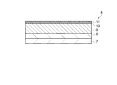
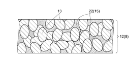
本実施形態では、電極複合体を有するリチウム電池と、このリチウム電池を製造するリチウム電池の製造方法との特徴的な例について、図に従って説明する。リチウム電池の製造方法には電極複合体が含まれている。本実施形態に係る電極複合体について図1に従って説明する。図1は電極複合体の構造を示す要部模式側断面図である。図1に示すように、電極複合体9は活物質集合体12を備えている。活物質集合体12は形成材料である活物質粒子13が複数連結した多孔質の成形体である。活物質粒子13同士の間には連通孔14が位置する。連通孔14では活物質粒子13間の空洞が網目状に連通して孔の形態になっている。
(First embodiment)
In the present embodiment, characteristic examples of a lithium battery having an electrode assembly and a method of manufacturing a lithium battery for manufacturing the lithium battery will be described with reference to the drawings. The method for manufacturing a lithium battery includes an electrode composite. The electrode assembly according to this embodiment will be described with reference to FIG. FIG. 1 is a schematic cross-sectional side view of an essential part showing the structure of an electrode assembly. As shown in FIG. 1, the
連通孔14には結晶質の固体電解質15が設置されている。連通孔14が網目状に設置されているので、活物質集合体12と固体電解質15とが広い面積で接触する。この為、活物質集合体12と固体電解質15との間でリチウムイオンが移動し易くなっている。また、固体電解質15は活物質集合体12間の連通孔14を埋めている。従って、固体電解質15は網目状の連続した構成物になっている。固体電解質15内はリチウムイオンが移動する。そして、連通孔14に固体電解質15が網目状に充填されているので、活物質集合体12の隅々までリチウムイオンが移動可能な経路が確保されることになる。このため、リチウムイオンが移動し易くなっている。
A crystalline
活物質粒子13の形成材料にはリチウム複酸化物を用いることができる。尚、リチウムを必ず含み2種以上の金属イオンを含む酸化物であり、オキソ酸イオンが存在しないものをリチウム複酸化物と称す。リチウム複酸化物としては、例えば、LiCoO2、LiNiO2、LiMn2O4、Li2Mn2O3、LiFePO4、Li2FeP2O7、LiMnPO4、LiFeBO3、Li3V2(PO4)3、Li2CuO2、LiFeF3、Li2FeSiO4、Li2MnSiO4等が挙げられる。
A lithium double oxide can be used as a material for forming the
他にも、これらのリチウム複酸化物の結晶内の一部原子が他の遷移金属、典型金属、アルカリ金属、アルカリ希土類、ランタノイド、カルコゲナイド、ハロゲン等で置換された固溶体もリチウム複酸化物に含むものとし、これら固溶体も正極活物質として用いることができる。本実施形態では、例えば、活物質粒子13にLiCoO2を用いている。
In addition, solid solutions in which some atoms in the crystal of these lithium double oxides are substituted with other transition metals, typical metals, alkali metals, alkali rare earths, lanthanoids, chalcogenides, halogens, etc. are also included in lithium double oxides. These solid solutions can also be used as the positive electrode active material. In the present embodiment, for example, LiCoO 2 is used for the
活物質粒子13の平均粒径は、300nm以上5μm以下が好ましく、450nm以上3μm以下がより好ましく、500nm以上1μm以下がさらに好ましい。この平均粒径の活物質粒子13を用いるとき活物質集合体12に含まれる連通孔14の割合を、好ましい範囲内に設定することができる。これにより、活物質集合体12の表面積を相対的に広くすることができる為、活物質集合体12と固体電解質15との接触面積を広くすることができる。
The average particle size of the
固体電解質15の材料にはLi2+XC1-XBXO3が用いられている。Xはホウ素Bの置換率であり、0を超え1以下の実数を表す。従って、固体電解質の固形物にXが0のときのLi2CO3は含まれず、Xが1のときのLi3BO3は含まれる。固体電解質15は結晶質である。
Li 2 + X C 1-X B X O 3 is used as the material of the
次に、リチウム電池について図2〜図5に従って説明する。図2はリチウム電池の外形を示す概略斜視図である。図2に示すように、電池としてのリチウム電池1は有底円筒形の容器部2と蓋部3とを備えている。容器部2及び蓋部3の一方が正極になり他方が負極になる。リチウム電池1は蓄電可能な全固体型二次電池であるが一次電池として用いてもよい。リチウム電池1の内部に電極複合体9が用いられている。
Next, the lithium battery will be described with reference to FIGS. FIG. 2 is a schematic perspective view showing the outer shape of the lithium battery. As shown in FIG. 2, a lithium battery 1 as a battery includes a bottomed
図3はリチウム電池1の構造を示す模式断面図である。図3に示すように、容器部2内には円板状の電池としての電池ユニット4が4個重ねて設置されている。電池ユニット4は円柱状に重ねられている。各電池ユニット4に電極複合体9が用いられている。1つのリチウム電池1に設置される各電池ユニット4の個数は特に限定されない。1個〜3個でも良く、5個以上でも良い。電池ユニット4は約2.8v〜約4.2vの間で用いられる。複数の電池ユニット4の接続を並列接続及び直列接続で組み合わせることにより、リチウム電池1として必要な電圧値を調整することができる。
FIG. 3 is a schematic cross-sectional view showing the structure of the lithium battery 1. As shown in FIG. 3, four
重ねられた電池ユニット4の回りには円筒状の第1絶縁部5が設置されている。電池ユニット4及び第1絶縁部5の図中上側には蓋部3が設置され、蓋部3の外周側及び第1絶縁部5の側面側に第2絶縁部6が設置されている。第2絶縁部6は容器部2と蓋部3との間に位置し、容器部2と第1絶縁部5との間にも位置している。
A cylindrical first insulating
電池ユニット4が図中左右方向に移動しないように第1絶縁部5が電池ユニット4を固定する。さらに、第1絶縁部5は電池ユニット4の側面が容器部2と導通しないように絶縁する。第2絶縁部6は容器部2と蓋部3とを絶縁する。容器部2及び蓋部3の材料は導通性及び剛性があれば良く特に限定されないが耐食性のある金属や、表面に耐食性の表面処理おこなった金属を用いることができる。本実施形態では、例えば、容器部2及び蓋部3の材料にステンレスを用いている。第1絶縁部5及び第2絶縁部6の材料は絶縁性があれば良く特に限定されないが、樹脂材料を用いるのが加工し易いので好ましい。本実施形態では、例えば、第1絶縁部5及び第2絶縁部6の材料にアクリル樹脂を用いている。
The first insulating
図4は電池ユニットの構造を示す模式側面図である。図4に示すように、電池ユニット4は第1電極としての下部電極7を備えている。そして、下部電極7上にカーボンシート8、第1の層としての電極複合体9、第2の層としての分離膜10、第2電極としての上部電極11がこの順に重ねて設置されている。各部位の厚みは特に限定されないが、本実施形態では、例えば、下部電極7が約100μm、カーボンシート8が約100μm、電極複合体9が約300μm、分離膜10が約2μm、上部電極11が約2μmである。
FIG. 4 is a schematic side view showing the structure of the battery unit. As shown in FIG. 4, the
下部電極7は正極となる電極であり、構造を維持する基板として機能する。下部電極7の材料には、例えば、銅、マグネシウム、チタン、鉄、コバルト、ニッケル、亜鉛、アルミニウム、ゲルマニウム、インジウム、金、白金、銀及びパラジウムからなる群から選ばれる1種の金属や、この群から選ばれる2種以上の金属を含む合金等を用いることができる。本実施形態では、例えば、下部電極7の材料に銅を用いている。カーボンシート8は下部電極7と電極複合体9との間で効率良く電流を流動させる炭素膜である。
The
分離膜10は電極複合体9と上部電極11とが短絡することを防止する膜でありLBO(ほう酸三リチウム)、LCBO(ホウ酸炭素リチウム)等により構成された膜である。本実施形態では、例えば、分離膜10にLCBOを採用した。また、上部電極11は負極となる電極であり、リチウムの膜を用いた。
The
リチウム電池1を充電するとき固体電解質15ではリチウムイオンが電極複合体9の活物質集合体12から上部電極11に移動する。上部電極11はリチウム膜の負極である。そして、放電するときには固体電解質15ではリチウムイオンが上部電極11から電極複合体9の活物質集合体12に移動する。
When the lithium battery 1 is charged, lithium ions move from the
図5は電池ユニットの構造を示す模式平面図である。図5に示すように、電池ユニット4の平面形状は円形になっている。これに合わせる形で、本実施形態においては、下部電極7、カーボンシート8及び電極複合体9も円板状になっている。電池ユニット4の直径は特に限定されないが、本実施形態では、例えば、10mm〜20mmに設定している。
FIG. 5 is a schematic plan view showing the structure of the battery unit. As shown in FIG. 5, the planar shape of the
次に上述したリチウム電池1の製造方法について図6〜図17にて説明する。図6は、リチウム電池の製造方法のフローチャートであり、図7〜図16はリチウム電池の製造方法を説明するための模式図である。図6のフローチャートにおいて、ステップS1は活物質シート形成工程である。この工程は、活物質粒子13とバインダーとを混成してシート状に加工する工程である。次にステップS2に移行する。ステップS2は外形形成工程である。この工程は、活物質集合体12の中間製品の外形を形成する工程である。中間製品は完成に至る途中の製品を称す。次にステップS3に移行する。ステップS3は活物質焼成工程である。この工程は、活物質集合体12の中間製品からバインダーを除去し活物質粒子13を焼結する工程である。次にステップS4に移行する。
Next, a method for manufacturing the above-described lithium battery 1 will be described with reference to FIGS. FIG. 6 is a flowchart of a method for manufacturing a lithium battery, and FIGS. 7 to 16 are schematic diagrams for explaining a method for manufacturing a lithium battery. In the flowchart of FIG. 6, step S1 is an active material sheet forming step. This step is a step in which the
ステップS4は電解質供給工程である。この工程は、活物質集合体12上に固体電解質15の材料を供給する工程である。次にステップS5に移行する。ステップS5は充填工程である。この工程は、固体電解質15の材料を加熱して活物質集合体12の連通孔14に充填させる工程である。次にステップS6に移行する。ステップS6は徐冷工程である。この工程は、固体電解質15の材料を充填させた活物質集合体12を徐冷する工程である。ステップS6で電極複合体9が完成する。ステップS1〜ステップS6が電極複合体9の製造方法を示している。次にステップS7に移行する。
Step S4 is an electrolyte supply process. This step is a step of supplying the material of the
ステップS7は分離層設置工程である。この工程は、電極複合体9の一方の面に分離膜10を設置する工程である。次にステップS8に移行する。ステップS8は上電極設置工程である。この工程は、分離膜10に重ねて上部電極11を設置する工程である。次にステップS9に移行する。ステップS9は下電極設置工程である。この工程は、電極複合体9の他方の面にカーボンシート8及び下部電極7を設置する工程である。ステップS9で電池ユニット4が完成する。次にステップS10に移行する。ステップS10はパッケージ工程である。この工程は、容器部2に電池ユニット4、第1絶縁部5、第2絶縁部6及び蓋部3を設置して、容器部2で蓋部3を固定する工程である。以上の工程によりリチウム電池1が完成する。ステップS1〜ステップS3が第1の工程に相当し、ステップS4が第2の工程に相当する。ステップS5が第3の工程に相当する。ステップS6が第4の工程に相当する。
Step S7 is a separation layer installation process. This step is a step of installing the
次に、図7〜図17を用いて、図6に示したステップと対応させて、製造方法を詳細に説明する。 Next, the manufacturing method will be described in detail with reference to FIGS. 7 to 17 in association with the steps shown in FIG.
図7はステップS1の活物質シート形成工程に対応する図である。ステップS1では活物質粒子13の原料粉末をバインダー等と混ぜてペースト状にする。そして、プラスチックのキャリアフィルム上に薄いシート状に延ばして乾燥する。乾燥されたシートをグリーンシートと称す。
FIG. 7 is a diagram corresponding to the active material sheet forming step of step S1. In step S1, the raw material powder of the
バインダーは活物質粒子13の原料粉末を接合し加熱により除去可能であれば良く特に限定されない。バインダーはポリカーボネートの他、セルロース系バインダー、アクリル系バインダー、ポリビニルアルコール系バインダー、ポリビニルブチラール系バインダー等が挙げられ、これらのうちの1種または2種以上を組み合わせて用いることができる。
The binder is not particularly limited as long as the raw material powder of the
また、活物質シート形成工程において溶媒を用いてもよい。当該工程で用いる溶媒としては、特に限定されないが、例えば、ブタノール、エタノール、プロパノール、メチルイソブチルケトン、トルエン、キシレン等の非プロトン性の溶媒を用いることができる。これにより、溶媒との接触による活物質粒子13の劣化を低減することができる。これらの溶媒を1つまたは複数組み合わせて使用することができる。本実施形態では、例えば、バインダーはポリカーボネートにジオキサンを加えて用いている。
Moreover, you may use a solvent in an active material sheet formation process. Although it does not specifically limit as a solvent used at the said process, For example, aprotic solvents, such as butanol, ethanol, propanol, methyl isobutyl ketone, toluene, xylene, can be used. Thereby, deterioration of the
また、バインダーにはポリフッ化ビニリデンやポリビニルアルコール等の有機高分子化合物をくわえても良い。バインダーには連通孔14の大きさを調整するために粒子状の造孔材を添加してもよい。造孔材の平均粒径は特に限定されないが本実施形態では、例えば、0.5μm〜10μmに設定している。他にも、バインダーにはポリアクリル酸等の潮解性を有する物質を形成材料とする粒子を加えてもよい。粒子が潮解して粒子の周囲に生じる水が、粒子状のリチウム複酸化物をつなぎ合わせる。粒子状のリチウム複酸化物をつなぎ合わせるバインダーとして機能する。
The binder may contain an organic polymer compound such as polyvinylidene fluoride or polyvinyl alcohol. In order to adjust the size of the
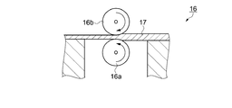
次に、図7に示すように、圧延機16にグリーンシート17を設置する。圧延機16は第1円筒16aと第2円筒16bを備えている。そして、第1円筒16aの中心軸及び第2円筒16bの中心軸は図示しない回転機構の回転軸に接続されている。回転機構はモーター、減速機及び回転速度を制御する制御装置等により構成されている。回転機構により第1円筒16aは反時計回りに回転し、第2円筒16bは時計回りに回転する。第1円筒16aの外周と第2円筒16bの外周との距離は所定の距離に調整されている。
Next, as shown in FIG. 7, a
第1円筒16aと第2円筒16bとの間にグリーンシート17を図中右側から挟む。第1円筒16a及び第2円筒16bが回転することによりグリーンシート17は所定の厚みに圧延されて図中左側に排出される。第1円筒16a及び第2円筒16bの表面が鏡面に加工されている。そして、圧延されたグリーンシート17には第1円筒16a及び第2円筒16bの表面が転写されるので、グリーンシート17の表面は平坦な面になる。
A
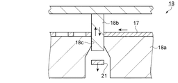
図8はステップS2の外形形成工程に対応する図である。図8に示すように、ステップS2において、グリーンシート17をプレス機18に設置する。プレス機18はダイプレート18a及びポンチ18bを備えている。そして、ダイプレート18aには円形の孔18cが設置され、ポンチ18bは円柱形状になっている。孔18cの直径とポンチ18bの直径は略同じ寸法になっている。
FIG. 8 is a diagram corresponding to the outer shape forming process of step S2. As shown in FIG. 8, in step S <b> 2, the
操作者はダイプレート18a上にグリーンシート17を設置する。そして、プレス機18がポンチ18bを図中上下方向に移動させる。このとき、グリーンシート17はポンチ18bに押し出されてダイプレート18aの孔18cを通過する。そして、グリーンシート17が円板状に形成された活物質円板21が形成される。プレス機18はグリーンシート17を図中左側に移動してポンチ18bを上下動することにより活物質円板21を続けて形成する。
The operator installs the
図9はステップS3の活物質焼成工程に対応する図である。ステップS3の活物質焼成工程では、まず、活物質円板21からバインダーを除去する脱脂工程を行う。活物質円板21を還元ガス中に設置して150〜500℃程度の温度雰囲気内で0.1〜20時間程度加熱する。これにより、活物質円板21からバインダーを除去することができる。次に、活物質粒子13が溶融しない程度の温度まで加熱する。LiCoO2の融点は1100℃であるので、1100℃未満の温度まで加熱する。加熱温度及び加熱時間は特に限定されないが本実施形態では、例えば、加熱温度を900〜950℃とし、加熱時間を4〜14時間程度にしている。その結果、図9に示すように活物質粒子13が結合して活物質集合体12が完成する。活物質粒子13同士の間には連通孔14が設置される。連通孔14はバインダーが除去されてできた空洞であり、空洞が連なって連通孔14になっている。活物質集合体12には連通孔14が多く設置されているので多孔体や多孔質とも称される。
FIG. 9 is a diagram corresponding to the active material firing step of step S3. In the active material firing step of step S3, first, a degreasing step of removing the binder from the
図10はステップS4の電解質供給工程に対応する図である。図10に示すように、ステップS4において、活物質集合体12上に活物質集合体12と接するように固体電解質15の材料である固形物としての固形の電解質22を供給する。固形の電解質22は固体電解質15の材料であり、固体電解質15の固形物である。固形の電解質22は特に限定されず、粉体、シート状、ブロック状の各種の形態で供給することができる。本実施形態では、例えば、固形の電解質22は紛体の状態で供給される。
FIG. 10 is a diagram corresponding to the electrolyte supply step of step S4. As shown in FIG. 10, in step S <b> 4, a
ホウ素Bの置換率であるXが0を超え1以下の実数とするとき、固形の電解質22はLi2+XC1-XBXO3を含む。Xは0を超えた実数であれば良く、例えば、Xが0.1のとき、Li2+XC1-XBXO3はLi2.1C0.9B0.1O3であり、Xが1のとき、Li2+XC1-XBXO3はLi3BO3である。
When X, which is the substitution rate of boron B, is a real number greater than 0 and equal to or less than 1, the
図11及び図12はステップS5の充填工程に対応する図である。図11に示すように、ステップS5において、活物質集合体12を載置台23上に載置する。載置台23は耐熱性があり、1000度以上の高温に耐える。載置台23の材質にはアルミナや炭化ケイ素等のセラミックを用いることができる。
11 and 12 are diagrams corresponding to the filling step of step S5. As shown in FIG. 11, in step S <b> 5, the
次に、活物質集合体12及び固形の電解質22を加熱する。予め加熱された電気炉内に固形の電解質22が設置された活物質集合体12を投入する。電気炉内では固形の電解質22が加熱されて溶融する。固形の電解質22が溶融したものを溶融物と称す。図12に示すように、溶融物には重力が作用するので、溶融物は活物質集合体12の連通孔14に充填される。さらに、毛管現象が作用し、溶融物は連通孔14内に容易に充填される。尚、載置台23は多孔質セラミック等の多孔質の構造体にしても良い。そして、活物質集合体12から溢れた固形の電解質22の溶融物を載置台23に吸着させても良い。
Next, the
固形の電解質22を充填させるとき溶媒を用いずに加熱して溶融させて液体にしている。連通孔14内に充填された固形の電解質22の溶融物が固化するとき気化する物質の量が少ないので、固形の電解質22の体積変化を小さくすることができる。従って、固形の電解質22の溶融物が固化した後の、連通孔14における空隙率の低下を図ることができる。
When the
固形の電解質22を溶融させるとき、固形の電解質22を650度以上900度以下の範囲で加熱する。加熱温度を650度以上にすることで固形の電解質22の固形物を溶融することができる。加熱温度を900度以上にするとき固形の電解質22の組成が変わるので電解質としての性能が低下する。従って、固形の電解質22の加熱温度を650度以上900度以下の範囲にすることにより、電解質としての性能を低下させずに固形の電解質22を溶融させることができる。
When the
さらには、固形の電解質22を溶融させるときの加熱温度は700度以上850度以下が好ましい。そして、固形の電解質22の加熱温度は固形の電解質22の組成に応じて変えるのが好ましい。固形の電解質22を溶解するにはLi2+XC1-XBXO3におけるホウ素置換率Xの値に応じて融点がかわるので加熱温度を変更するのが好ましい。
Furthermore, the heating temperature when melting the
固形の電解質22の加熱時間は固形の電解質22の量によって異なるので限定されない。加熱時間が長いと固形の電解質22の組成が変わるので加熱時間は短い方が好ましい。固形の電解質22が20mgのときの加熱時間は4分以上6分以下が好ましい。本実施形態では、例えば、固形の電解質22が20mgのときの加熱時間を5分に設定した。
The heating time of the
ステップS6の徐冷工程において、固形の電解質22が充填された活物質集合体12を徐冷する。これにより、固形の電解質22の溶融物が固化して結晶化する。徐冷するときの雰囲気温度が高いときには結晶の粒径が大きくなり、雰囲気温度が低いときには結晶の粒径が小さくなる。雰囲気温度を調整することで結晶粒径を制御することができる。固形の電解質22の溶融物が固化して固体電解質15になり、電極複合体9が完成する。尚、電極複合体9の両面を研磨して平坦にしても良い。電極との接触抵抗を低くすることができる。
In the slow cooling step of step S6, the
図13はステップS7の分離層設置工程に対応する図である。図13に示すように、ステップS7において、活物質集合体12上に分離膜10を設置する。分離膜10はLCBOの膜である。分離膜10の成膜方法は特に限定されず、スパッタリング法、真空蒸着法等の気相成膜法の他、塗布法、噴霧法等の液相成膜法を用いることができる。本実施形態では、例えば、スパッタリング法を用いて分離膜10を成膜した。電極複合体9上に分離膜10が設置された形態を分離膜付電極複合体25とする。
FIG. 13 is a diagram corresponding to the separation layer installation step of step S7. As shown in FIG. 13, in step S <b> 7, the
図14はステップS8の上電極設置工程に対応する図である。図14に示すように、ステップS8において、分離膜10上に上部電極11を設置する。上部電極11はリチウムの膜である。上部電極11の成膜方法は分離膜10と同様の方法を用いることができ、成膜方法は特に限定されないが本実施形態では、例えば、真空蒸着法を用いて上部電極11を成膜した。
FIG. 14 is a diagram corresponding to the upper electrode installation step in step S8. As shown in FIG. 14, the
図15はステップS9の下電極設置工程に対応する図である。図15に示すように、ステップS9において、下部電極7上にカーボンシート8を設置する。下部電極7とカーボンシート8とは接着せずに接触していればよい。さらに、カーボンシート8上に電極複合体9を重ねて設置する。カーボンシート8と電極複合体9とは接着せずに接触していればよい。以上の工程により電池ユニット4が完成する。
FIG. 15 is a diagram corresponding to the lower electrode installation step in step S9. As shown in FIG. 15, in step S <b> 9, the
図16はステップS10のパッケージ工程に対応する図である。図16に示すように、ステップS10において、電池ユニット4を4個重ねる。電池ユニット4を並列結合するときには、絶縁シートを電池ユニット4の間に設置し、各電池ユニット4を接続する配線を設置しておく。次に、第1絶縁部5の中央の孔に電池ユニット4を配置する。さらに、電池ユニット4の上に蓋部3を設置する。そして、蓋部3を電池ユニット4と接触させる。
FIG. 16 is a diagram corresponding to the packaging process in step S10. As shown in FIG. 16, in step S10, four
次に、蓋部3の外周及び第1絶縁部5の側面に沿って第2絶縁部6を挿入する。続いて、第2絶縁部6が挿入された蓋部3、電池ユニット4及び第1絶縁部5を容器部2の中に設置する。次に、容器部2の開放端を蓋部3側に折り曲げて硬く密着させる。これにより、各電池ユニット4は加圧されるので、下部電極7、カーボンシート8及び電極複合体9は電気的に接続する。以上の工程によりリチウム電池1が完成する。
Next, the second insulating
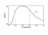
図17は固形の電解質のホウ素置換率Xと電極複合体のLi伝導率の関係を示すグラフである。図17において、横軸はステップS4の電解質供給工程で設置した固形の電解質22のホウ素置換率Xを示す。ホウ素置換率XはLi2+XC1-XBXO3におけるXである。縦軸はステップS6の徐冷工程を経て完成した電極複合体9のLi伝導率を示す。Li伝導率推移線24はホウ素置換率Xに対するLi伝導率を示している。
FIG. 17 is a graph showing the relationship between the boron substitution rate X of the solid electrolyte and the Li conductivity of the electrode assembly. In FIG. 17, the horizontal axis represents the boron substitution rate X of the
Li伝導率推移線24が示すように、ホウ素置換率Xが0.2より低いとき、ホウ素置換率Xに対するLi伝導率の変化が大きい。そして、ホウ素置換率Xが0.2のときに比べてLi伝導率が低い。Li伝導率が高い方がリチウム電池1の性能が良いので、ホウ素置換率Xは0.2未満に設定しない方が良い。
As indicated by the Li
同様に、ホウ素置換率Xが0.6より大きいとき、ホウ素置換率Xに対するLi伝導率の変化が大きい。そして、ホウ素置換率Xが0.6のときに比べてLi伝導率が低い。Li伝導率が高い方がリチウム電池1の性能が良いので、ホウ素置換率Xは0.6を超える数値に設定しない方が良い。従って、ホウ素置換率Xは0.2以上0.6以下の実数に設定するこが好ましい。このとき、ホウ素置換率Xが変動してもLi伝導率が高い状態を維持することができる。Li伝導率が高い電池はLi伝導率が低い電池に比べて短時間に充電することができる。そして、放電時には内部抵抗が低くなるので、電圧降下を低くすることができる。 Similarly, when the boron substitution rate X is greater than 0.6, the change in Li conductivity with respect to the boron substitution rate X is large. The Li conductivity is lower than when the boron substitution rate X is 0.6. Since the performance of the lithium battery 1 is better when the Li conductivity is higher, the boron substitution rate X should not be set to a value exceeding 0.6. Therefore, the boron substitution rate X is preferably set to a real number of 0.2 to 0.6. At this time, even if the boron substitution rate X varies, the state where the Li conductivity is high can be maintained. A battery having a high Li conductivity can be charged in a shorter time than a battery having a low Li conductivity. And since internal resistance becomes low at the time of discharge, a voltage drop can be made low.
上述したように、本実施形態によれば、以下の効果を有する。
(1)本実施形態によれば、Li2+XC1-XBXO3を固体電解質15にするとき溶媒を用いずに加熱して溶融して液体にしている。この為、連通孔14内に充填した固形の電解質22の溶融物が固化するとき気化する物質の量が少ないので、固形の電解質22の体積の変化を小さくできる。従って、固化した後の連通孔14における空隙率の低下を図ることができる。従って、1回の工程で溶融物を連通孔14内に充填させることができる為、生産性良く固体電解質15を活物質集合体12の連通孔14内に設置することができる。
As described above, this embodiment has the following effects.
(1) According to this embodiment, when Li 2 + X C 1-X B X O 3 is used as the
(2)本実施形態によれば、固形の電解質22を650度以上900度以下の範囲で加熱している。加熱温度を650度以上にするとき固形の電解質22を溶融することができる。加熱温度を900度以上にするとき固形の電解質22の組成が変わるので電解質としての性能が低下する。従って、固形の電解質22の加熱温度を上記の範囲にすることにより、電解質としての性能を低下させずに固形の電解質22の固形物を溶融させることができる。
(2) According to this embodiment, the
(3)本実施形態によれば、Li2+XC1-XBXO3におけるXの範囲は0.2以上0.6以下の実数である。このとき、ホウ素置換率Xが変動しても固体電解質のLi伝導率を安定して高い状態を維持することができる。 (3) According to the present embodiment, the range of X in Li 2 + X C 1-X B X O 3 is a real number of 0.2 or more and 0.6 or less. At this time, even if the boron substitution rate X varies, the Li conductivity of the solid electrolyte can be stably maintained at a high level.
(4)本実施形態によれば、電池ユニット4では電極複合体9が下部電極7と上部電極11とに挟まれている。そして、電極複合体9は生産性良く製造できる電極複合体9であるので、電池ユニット4は生産性良く製造できる電極複合体9を備えた電池とすることができる。
(4) According to this embodiment, in the
(5)本実施形態によれば、リチウム電池1は電池ユニット4を4個備えている。そして、電池ユニット4は生産性良く製造できる電極複合体9を備えている。従って、本実施形態のリチウム電池1は生産性良く製造できる電極複合体9を備えた電池とすることができる。
(5) According to the present embodiment, the lithium battery 1 includes four
(第2の実施形態)
次に、本発明を具体化した電極複合体の一実施形態について図18の電極複合体の構造を示す模式側断面図を用いて説明する。この実施形態が第1の実施形態と異なるところは、図13に示した分離膜10が固体電解質15と同じ材質であり、連続している点にある。尚、第1の実施形態と同じ点については説明を省略する。
(Second Embodiment)
Next, an embodiment of an electrode assembly embodying the present invention will be described with reference to a schematic side sectional view showing the structure of the electrode assembly of FIG. This embodiment is different from the first embodiment in that the
すなわち、本実施形態では、図18に示すように、電極複合体としての分離膜付電極複合体27は第1の層としての電極複合体9の層及び第2の層としての分離膜28とを有し、電極複合体9における固体電解質15と分離膜28における固体電解質とは連続している。このように形成された固体電解質15と分離膜28は連続した結晶構造を有し、好ましいLiイオンの伝導度を有する分離膜付電極複合体27とすることができる。
That is, in this embodiment, as shown in FIG. 18, the
前記第1の実施形態では、ステップS3〜ステップS5で活物質粒子13の連通孔14に固体電解質15を充填した。次に、ステップS7で分離膜10を設置した。ステップS4において、活物質集合体12上に設置する固形の電解質22の量を、固化し結晶化した後に活物質集合体12上に分離膜10を形成することができる量に設定する。これにより、ステップS6の徐冷工程では活物質集合体12上に分離膜28が形成される。本実施形態ではステップS7を省略され、ステップS6の次にステップS8が行われる。従って、少ない工程で分離膜28が設置された電極複合体9を製造することができる。尚、本実施形態でもステップS1〜ステップS6が電極複合体の製造方法となっている。
In the first embodiment, the
電極複合体9における活物質集合体12に固体電解質15の材料を充填して、続けて、電極複合体9の上に固形の電解質22を設置している。この方法では、電極複合体9と分離膜28とを続けて設置することができる。従って、分離膜付電極複合体27は生産性良く電極複合体9及び分離膜28を製造できる構造を有する分離膜付電極複合体27とすることができる。
The
尚、本実施形態は上述した実施形態に限定されるものではなく、本発明の技術的思想内で当分野において通常の知識を有する者により種々の変更や改良を加えることも可能である。
(変形例1)
前記実施形態では、活物質円板21はグリーンシート17から形成した。活物質円板21は成形型に材料を投入して押圧して成形しても良い。
Note that the present embodiment is not limited to the above-described embodiment, and various changes and improvements can be added by those having ordinary knowledge in the art within the technical idea of the present invention.
(Modification 1)
In the embodiment, the
(変形例2)
前記実施形態では、ステップS5の充填工程において電気炉を用いて固形の電解質22を加熱した。固形の電解質22を他の方法で加熱しても良い。例えば、レーザー光線、高周波電磁波を照射してもよい。他にも固形の電解質22を溶融して活物質集合体12に滴下しても良い。
(Modification 2)
In the said embodiment, the
(変形例3)
前記実施形態では、活物質粒子13の連通孔14に固体電解質15を充填したものを電極複合体9とした。さらに、分離膜10を設置した状態を図13に示す電極複合体としての分離膜付電極複合体25としても良い。
(Modification 3)
In the embodiment, the
(変形例4)
前記実施形態ではリチウム電池1の電池ユニット4では電極複合体9上に分離膜10が設置されていた。変形例3に示す分離膜付電極複合体25を上部電極11と下部電極7とで挟んだ電池ユニットにしてもよい。さらに、この電池ユニットを用いてリチウム電池にしても良い。さらに、生産性良く製造できるリチウム電池にすることができる。
(Modification 4)
In the above embodiment, the
1…電池としてのリチウム電池、4…電池としての電池ユニット、7…第1電極としての下部電極、9…第1の層としての電極複合体、10…第2の層としての分離膜、11…第2電極としての上部電極、12…活物質集合体、13…活物質粒子、14…連通孔、15…固体電解質、22…固形物としての固形の電解質、25,27…電極複合体としての分離膜付電極複合体、28…層及び第2の層としての分離膜。 DESCRIPTION OF SYMBOLS 1 ... Lithium battery as a battery, 4 ... Battery unit as a battery, 7 ... Lower electrode as 1st electrode, 9 ... Electrode complex as 1st layer, 10 ... Separation membrane as 2nd layer, 11 ... upper electrode as second electrode, 12 ... active material aggregate, 13 ... active material particles, 14 ... communication hole, 15 ... solid electrolyte, 22 ... solid electrolyte as solid, 25, 27 ... as electrode composite Electrode assembly with a separation membrane, 28... And a separation membrane as a second layer.
Claims (4)
前記活物質集合体上にLi2+XC1-XBXO3(Xは0を超え1以下の実数を表す。)を含む固形物を設置する第2の工程と、
前記固形物を溶融させる第3の工程と、
前記固形物の溶融物を固化し結晶化させる第4の工程と、を含み、
前記溶融物は、前記第3の工程において前記連通孔内に充填されることを特徴とする電極複合体の製造方法。 A first step of forming an active material assembly having communication holes;
A second step of installing a solid material containing Li 2 + X C 1-X B X O 3 (X represents a real number of more than 0 and 1 or less) on the active material aggregate;
A third step of melting the solid,
A fourth step of solidifying and crystallizing the melt of the solid matter,
The method for producing an electrode assembly, wherein the melt is filled in the communication hole in the third step.
方法。 4. The electrode composite according to claim 1, wherein the amount of the solid matter is an amount capable of forming a layer on the active material aggregate after solidifying and crystallizing. 5. Body manufacturing method.
Priority Applications (5)
| Application Number | Priority Date | Filing Date | Title |
|---|---|---|---|
| JP2015208664A JP6597172B2 (en) | 2015-10-23 | 2015-10-23 | Electrode composite manufacturing method, electrode composite, and battery |
| CN201680057560.8A CN108370029B (en) | 2015-10-23 | 2016-09-26 | Method for producing electrode assembly, and battery |
| US15/764,260 US10770757B2 (en) | 2015-10-23 | 2016-09-26 | Manufacturing method of electrode assembly |
| PCT/JP2016/078205 WO2017068914A1 (en) | 2015-10-23 | 2016-09-26 | Electrode assembly manufacturing method, electrode assembly, and battery |
| US16/940,801 US20200358135A1 (en) | 2015-10-23 | 2020-07-28 | Manufacturing method of electrode assembly |
Applications Claiming Priority (1)
| Application Number | Priority Date | Filing Date | Title |
|---|---|---|---|
| JP2015208664A JP6597172B2 (en) | 2015-10-23 | 2015-10-23 | Electrode composite manufacturing method, electrode composite, and battery |
Publications (3)
| Publication Number | Publication Date |
|---|---|
| JP2017084477A JP2017084477A (en) | 2017-05-18 |
| JP2017084477A5 JP2017084477A5 (en) | 2018-09-20 |
| JP6597172B2 true JP6597172B2 (en) | 2019-10-30 |
Family
ID=58711272
Family Applications (1)
| Application Number | Title | Priority Date | Filing Date |
|---|---|---|---|
| JP2015208664A Active JP6597172B2 (en) | 2015-10-23 | 2015-10-23 | Electrode composite manufacturing method, electrode composite, and battery |
Country Status (1)
| Country | Link |
|---|---|
| JP (1) | JP6597172B2 (en) |
Families Citing this family (2)
| Publication number | Priority date | Publication date | Assignee | Title |
|---|---|---|---|---|
| JP6597183B2 (en) * | 2015-10-29 | 2019-10-30 | セイコーエプソン株式会社 | Electrode composite manufacturing method, electrode composite, and battery |
| JP6995135B2 (en) * | 2017-11-10 | 2022-01-14 | 日本碍子株式会社 | Secondary battery |
Family Cites Families (8)
| Publication number | Priority date | Publication date | Assignee | Title |
|---|---|---|---|---|
| JP2991256B2 (en) * | 1991-08-23 | 1999-12-20 | 日本電信電話株式会社 | Lithium ion conductive solid electrolyte material |
| JP6163774B2 (en) * | 2013-02-05 | 2017-07-19 | セイコーエプソン株式会社 | Method for producing composite and method for producing lithium battery |
| JP6201327B2 (en) * | 2013-02-05 | 2017-09-27 | セイコーエプソン株式会社 | Method for producing electrode composite for lithium battery, electrode composite for lithium battery, and lithium battery |
| JP2014154236A (en) * | 2013-02-05 | 2014-08-25 | Seiko Epson Corp | Method for manufacturing electrode composite body |
| JP2014154239A (en) * | 2013-02-05 | 2014-08-25 | Seiko Epson Corp | Method for manufacturing active material compact, active material compact, method for manufacturing lithium battery, and lithium battery |
| JP6464556B2 (en) * | 2014-01-31 | 2019-02-06 | セイコーエプソン株式会社 | Electrode composite manufacturing method, electrode composite, and battery |
| JP6299251B2 (en) * | 2014-02-10 | 2018-03-28 | セイコーエプソン株式会社 | Electrode composite manufacturing method, electrode composite, and battery |
| WO2015151144A1 (en) * | 2014-03-31 | 2015-10-08 | 株式会社日立製作所 | All-solid-state lithium secondary battery |
-
2015
- 2015-10-23 JP JP2015208664A patent/JP6597172B2/en active Active
Also Published As
| Publication number | Publication date |
|---|---|
| JP2017084477A (en) | 2017-05-18 |
Similar Documents
| Publication | Publication Date | Title |
|---|---|---|
| WO2017068914A1 (en) | Electrode assembly manufacturing method, electrode assembly, and battery | |
| US11876208B2 (en) | Thin film lithium conducting powder material deposition from flux | |
| CN106159312B (en) | Solid electrolyte battery, method for producing same, electrode assembly, and composite solid electrolyte | |
| CN112289977B (en) | Method for manufacturing electrode composite | |
| US10862162B2 (en) | Electrode composite body, method of manufacturing electrode composite body, and lithium battery | |
| US10916761B2 (en) | Low melting temperature metal purification and deposition | |
| KR20180107223A (en) | Segmented Cell Architecture for Solid State Batteries | |
| JP4575487B2 (en) | Lithium ion secondary battery and manufacturing method thereof | |
| JP2016025020A (en) | Electrode complex, lithium battery, and electrode complex manufacturing method | |
| CN103380515A (en) | Electrochemical device | |
| JP2017004783A (en) | Method for manufacturing electrode complex, electrode complex and lithium battery | |
| WO2013011568A1 (en) | Electrode for ion secondary batteries, method for producing electrode for ion secondary batteries, lithium ion secondary battery, and magnesium ion secondary battery | |
| KR20140031313A (en) | Solid electrolyte for lithium battery, comprising at least one zone of lithium-containing glass ceramic material and method of production. | |
| CN113871696A (en) | All-solid-state thick film lithium battery and preparation method thereof | |
| JP6597172B2 (en) | Electrode composite manufacturing method, electrode composite, and battery | |
| JP6597183B2 (en) | Electrode composite manufacturing method, electrode composite, and battery | |
| US20140287303A1 (en) | Electrode and method for manufacturing an electrode | |
| JP2016213105A (en) | Active material mold manufacturing method, electrode composite manufacturing method, and lithium battery manufacturing method | |
| JP2010251194A (en) | Positive electrode for battery and method of manufacturing the same | |
| JP6828788B2 (en) | Method for manufacturing electrode composite | |
| JP2017168393A (en) | Electrode composite manufacturing method, and lithium battery | |
| JP2010056093A (en) | Lithium ion secondary battery |
Legal Events
| Date | Code | Title | Description |
|---|---|---|---|
| A521 | Written amendment |
Free format text: JAPANESE INTERMEDIATE CODE: A523 Effective date: 20180807 |
|
| A621 | Written request for application examination |
Free format text: JAPANESE INTERMEDIATE CODE: A621 Effective date: 20180807 |
|
| RD05 | Notification of revocation of power of attorney |
Free format text: JAPANESE INTERMEDIATE CODE: A7425 Effective date: 20180906 |
|
| RD03 | Notification of appointment of power of attorney |
Free format text: JAPANESE INTERMEDIATE CODE: A7423 Effective date: 20181116 |
|
| A131 | Notification of reasons for refusal |
Free format text: JAPANESE INTERMEDIATE CODE: A131 Effective date: 20190528 |
|
| A521 | Written amendment |
Free format text: JAPANESE INTERMEDIATE CODE: A523 Effective date: 20190718 |
|
| TRDD | Decision of grant or rejection written | ||
| A01 | Written decision to grant a patent or to grant a registration (utility model) |
Free format text: JAPANESE INTERMEDIATE CODE: A01 Effective date: 20190903 |
|
| A61 | First payment of annual fees (during grant procedure) |
Free format text: JAPANESE INTERMEDIATE CODE: A61 Effective date: 20190916 |
|
| R150 | Certificate of patent or registration of utility model |
Ref document number: 6597172 Country of ref document: JP Free format text: JAPANESE INTERMEDIATE CODE: R150 |