JP6595872B2 - Semiconductor integrated circuit device and manufacturing method thereof - Google Patents
Semiconductor integrated circuit device and manufacturing method thereof Download PDFInfo
- Publication number
- JP6595872B2 JP6595872B2 JP2015194572A JP2015194572A JP6595872B2 JP 6595872 B2 JP6595872 B2 JP 6595872B2 JP 2015194572 A JP2015194572 A JP 2015194572A JP 2015194572 A JP2015194572 A JP 2015194572A JP 6595872 B2 JP6595872 B2 JP 6595872B2
- Authority
- JP
- Japan
- Prior art keywords
- type
- region
- concentration
- mos transistor
- channel mos
- Prior art date
- Legal status (The legal status is an assumption and is not a legal conclusion. Google has not performed a legal analysis and makes no representation as to the accuracy of the status listed.)
- Active
Links
Images


Description
本発明は、N型半導体基板を使用した、30V以上の電源電圧を必要とする半導体集積回路装置およびその製造方法に関する。 The present invention relates to a semiconductor integrated circuit device using an N-type semiconductor substrate and requiring a power supply voltage of 30 V or more, and a manufacturing method thereof.
電気機器に用いられる電気回路は電池などの外部電源により駆動されるが、この外部電源の電圧値が変動すると電気回路の誤動作や様々な異常現象を引き起こす可能性があるので、外部電源を調整し一定電圧を出力したり、電源の変動をモニタリングしたりするようなパワーマネジメントICを電気回路と外部電源との間に設置し、安定動作を図るのが一般的である。 The electrical circuit used in electrical equipment is driven by an external power source such as a battery.If the voltage value of the external power source fluctuates, it may cause malfunction of the electrical circuit and various abnormal phenomena. In general, a power management IC that outputs a constant voltage or monitors fluctuations in a power supply is installed between an electric circuit and an external power supply to achieve stable operation.
パワーマネジメントICに求められる要求の1つとして高電圧入力/低電圧出力があるが、それに対応するためには半導体集積回路装置内に高電圧用信号処理の領域と低電圧用信号処理の領域を設ける必要がある。具体的には出力回路や内部論理回路などに向けた低耐圧用の素子を用いた低電圧用信号処理領域と、入力回路や一部の出力回路などに向けた高耐圧用の素子を用いた高電圧信号処理領域それぞれを用意する。このとき、高耐圧が必要となる回路では素子領域や素子分離領域を高耐圧に耐えうる構造にするために大きな所要面積が必要となるため、極力必要な部分のみ高耐圧素子や構造を用い、他の領域を低耐圧化することで半導体集積回路装置の高コスト化を抑制する工夫が重要となる。 One of the requirements for power management ICs is high-voltage input / low-voltage output. To meet these requirements, the high-voltage signal processing area and the low-voltage signal processing area are provided in the semiconductor integrated circuit device. It is necessary to provide it. Specifically, a low-voltage signal processing area using low-voltage elements for output circuits and internal logic circuits, and high-voltage elements for input circuits and some output circuits were used. Each high voltage signal processing region is prepared. At this time, in a circuit that requires a high breakdown voltage, a large required area is required to make the element region and the element isolation region a structure that can withstand the high breakdown voltage. It is important to devise measures for reducing the cost of the semiconductor integrated circuit device by lowering the breakdown voltage in other regions.
図6(1)に、このような低耐圧用のMOSトランジスタと高耐圧用のMOSトランジスタをP型半導体基板内の同一半導体集積回路内に形成した場合の模式断面図を示す。
P型半導体基板1の表面に設けられた低耐圧用のNMOSトランジスタ501は、第1のゲート絶縁膜9とその直上のゲート電極6及び両端に配置するドレイン/ソース領域とからなる。そのドレイン/ソース領域は、金属とコンタクトするための低抵抗で高濃度のN型不純物領域17と第1のN型低濃度不純物領域18とで構成する。
FIG. 6A is a schematic cross-sectional view in the case where such a low breakdown voltage MOS transistor and a high breakdown voltage MOS transistor are formed in the same semiconductor integrated circuit in the P-type semiconductor substrate.
The low breakdown
一方、高耐圧NMOSトランジスタ503は、ゲート絶縁膜9とその直上のゲート電極6及び両端に配置するドレイン/ソース領域とからなる。このドレイン/ソース領域は高濃度のN型不純物領域17及び第2のN型低濃度不純物領域19からなり、さらにN型低濃度不純物領域19上にはゲート絶縁膜よりも厚い絶縁膜13を形成している。この厚い絶縁膜はゲート/ドレイン間の電界緩和に効果があり有効である。
On the other hand, the high breakdown
このようなドレイン構造は30V以上のドレイン耐圧が必要とされる場合に採用され、主にドレイン側の第2のN型低濃度不純物領域19の長さと濃度によって耐圧調整がなされる。
Such a drain structure is employed when a drain withstand voltage of 30 V or higher is required, and the withstand voltage is adjusted mainly by the length and concentration of the second N-type low
この高耐圧NMOSトランジスタのN型高濃度領域17は、一般にプロセスコスト削減のために低耐圧NMOSトランジスタのN型高濃度不純物領域17と工程を共有し、砒素あるいはアンチモンを使用する。
The N-type high-
また、しばしば、第2のN型低濃度不純物領域19は、素子外領域のチャネルストップ構造と併用する事で工程の簡略化が図られる。このため第2のN型低濃度不純物領域19の上には、LOCOSプロセスで形成される絶縁膜13が配置され、N型低濃度不純物領域19の濃度は配線による濃度反転防止のための濃度に合わせられる。一般に半導体集積回路の中で高耐圧NMOSトランジスタが使用される頻度が低い場合は、これらのような簡略化のための構造上の制約が高耐圧NMOSトランジスタに課せられ、この制約の中で素子設計をすることになる。
In many cases, the second N-type low-
さらには、図6(2)に示すように高耐圧NMOSトランジスタについては、このN型高濃度不純物領域17の全体と、第2のN型低濃度不純物領域19の一部を覆うように、深さが数μmまで達する第3のN型低濃度不純物領域14を高耐圧NMOSトランジスタのドレイン側に設ける場合がある。これは、隣接するN型高濃度不純物領域17と第2のN型低濃度不純物領域19との境界の接触部分が少ないことを補完し、高耐圧NMOSトランジスタの電気的動作時にかかる高電圧と大電流による発熱破壊を防ぐ効果がある。またこのような破壊現象は瞬間的な破壊だけでなく、長期信頼性にも影響する。
Further, as shown in FIG. 6B, the high breakdown voltage NMOS transistor has a depth so as to cover the entire N-type high-
加えて、このようなドレイン側の深い拡散領域14は、ESD(Electrostatic Discharge)破壊などの耐性向上にも効果がある。その理由は、瞬間的に入ってくる静電気に起因したアンペアレベルの過大電流による発熱・温度上昇を、大きなN型拡散領域の体積と、半導体基板との間に形成される広いPN接合の接触面積で緩和し、PN接合破壊を抑制することができるからである(例えば、特許文献1参照)。 In addition, such a deep diffusion region 14 on the drain side is also effective in improving resistance such as ESD (Electrostatic Discharge) destruction. The reason for this is that the heat generation and temperature increase due to the ampere-level excessive current caused by the static electricity that instantaneously enters, the contact area of the large PN junction formed between the volume of the large N-type diffusion region and the semiconductor substrate This is because PN junction breakdown can be suppressed by relaxing (see, for example, Patent Document 1).
ところで、このような半導体集積回路に用いる半導体基板は、経済的な面からするとインゴット中の不純物濃度安定領域が広くウェハー収量が多いP型半導体基板が望ましいが、機能面やユーザからの要請でN型半導体基板を使用することは多い。 By the way, the semiconductor substrate used in such a semiconductor integrated circuit is preferably a P-type semiconductor substrate having a large impurity concentration stable region in the ingot and a high wafer yield from an economical viewpoint. In many cases, a type semiconductor substrate is used.
例えば、内部に集積化するNMOSトランジスタの精度を保つため、バックバイアスがかからないような構成にするためには、N型半導体基板を使用しそれぞれのNMOSトランジスタを形成するP型ウェル領域を分離し、それぞれのP型ウェル領域の電位を任意に変更するという方法を取る。 For example, in order to maintain the accuracy of the NMOS transistor integrated therein, in order to make a configuration in which a back bias is not applied, an N-type semiconductor substrate is used and a P-type well region for forming each NMOS transistor is separated, A method of arbitrarily changing the potential of each P-type well region is employed.
従来、N型半導体基板上に高耐圧NMOSトランジスタを集積化するには以下のような問題があった。
まず、図6(2)において高耐圧NMOSトランジスタのドレイン領域に形成するN型低濃度不純物領域14を高温長時間熱処理で形成していたために、そのままこの高耐圧NMOSトランジスタの領域全体をP型ウェル領域で包むにはさらに従来よりも深いP型ウェル拡散熱処理工程を必要とした。そのため両者のウェル領域を深く形成するために、1100℃以上の高温で長時間の熱処理を2回施す事が必要で、工期の長期化とともに、横方向への拡散の伸張による所要面積の増大が発生し、それらに伴う価格上昇が避けられなかった。
Conventionally, there has been the following problem in integrating a high voltage NMOS transistor on an N-type semiconductor substrate.
First, in FIG. 6 (2), since the N-type low concentration impurity region 14 formed in the drain region of the high breakdown voltage NMOS transistor is formed by high-temperature and long-time heat treatment, the entire region of the high breakdown voltage NMOS transistor is directly used as the P-type well. In order to wrap the region, a deeper P-type well diffusion heat treatment step is required than before. For this reason, in order to form both well regions deeply, it is necessary to perform heat treatment twice at a high temperature of 1100 ° C. or higher. As the construction period becomes longer, the required area increases due to the extension of diffusion in the lateral direction. As a result, price increases associated with them were inevitable.
また、縦方向の2重拡散の高耐圧化のためにエピタキシャル成長プロセスを利用したPN接合分離あるいはSOI基板などを使用した誘電体分離を採用する方法があるが、この方法は所要面積の増大は抑制できるものの、製造費用の増大が著しく、やはり価格の上昇を引き起こしていた。 In addition, there is a method of adopting PN junction separation using an epitaxial growth process or dielectric separation using an SOI substrate in order to increase the withstand voltage of vertical double diffusion, but this method suppresses an increase in required area. Although it was possible, the increase in manufacturing cost was remarkable, which also caused an increase in price.
また、深い拡散の形成に対する別の方法として、MeV(百万電子ボルト)級イオン注入法が挙げられるが、これは高額の装置が必要で、特に微細プロセスを採用しない廉価プロセスにより製造される製品では、装置費用の増大による製品コストの上昇を無視することはできない。 Another method for forming deep diffusion is the MeV (million electron volt) ion implantation method, which requires expensive equipment and is manufactured by a low-cost process that does not employ a fine process. Therefore, an increase in product cost due to an increase in equipment cost cannot be ignored.
一方、高耐圧NMOSトランジスタ503のドレイン領域にN型低濃度不純物領域14を形成しないでESDなどの耐性の向上を図ろうとする場合、ノイズ緩和用の抵抗体などの設置が必要になるが、発熱による破壊を防ぐために半導体集積回路装置の所要面積を左右する程の抵抗サイズが必要となり、やはりコストの上昇が避けられなかった。
On the other hand, when an attempt is made to improve the ESD resistance without forming the N-type low-concentration impurity region 14 in the drain region of the high-breakdown-
そこで、本発明はN型半導体基板を用いながら、従来のイオン注入・高温熱処理方法を用いても、工期の長期化を伴わずに30V以上の高耐圧とESD等に対する発熱破壊耐性を有する半導体集積回路装置およびその製造方法を提供することを課題とする。 Therefore, the present invention is a semiconductor integrated circuit that has a high breakdown voltage of 30 V or higher and a thermal breakdown resistance against ESD or the like without using a conventional ion implantation / high-temperature heat treatment method while using an N-type semiconductor substrate without increasing the construction period. It is an object of the present invention to provide a circuit device and a manufacturing method thereof.
本発明は上記課題を解決するために、以下のようにした。すなわち、
N型半導体基板に設けられた第1のP型ウェル領域内に形成された、
第1のゲート絶縁膜と、
多結晶シリコンからなる第1のゲート電極と、
N型の高濃度不純物領域からなる、第1のN型高濃度ドレイン領域及び第1のN型高濃度ソース領域と、
前記ゲート電極と、前記N型高濃度ドレイン領域及び前記N型高濃度ソース領域の間に形成された第1のN型低濃度ドレイン領域及び第1のN型低濃度ソース領域と、
を有するNチャネル型の低耐圧MOSトランジスタと、
前記第1のP型ウェル領域とは別の領域に前記第1のP型ウェル領域と接して設けられたN型ウェル領域内に形成された、
第2のゲート絶縁膜と、
多結晶シリコンからなる第2のゲート電極と、
P型の高濃度不純物領域からなる、P型高濃度ドレイン領域及びP型高濃度ソース領域と、
前記第2のゲート電極と、前記P型高濃度ドレイン領域及び前記P型高濃度ソース領域の間に形成されたP型低濃度ドレイン領域及びP型低濃度ソース領域と、
を有するPチャネル型の低耐圧MOSトランジスタと、
前記第1のP型ウェル領域とは接していない、前記第1のP型ウェル領域と同じ不純物濃度を有する第2のP型ウェル領域内に形成された、
第3のゲート絶縁膜と、
多結晶シリコンからなる第3のゲート電極と、
N型の高濃度不純物領域からなる、第3のN型高濃度ドレイン領域及び第3のN型高濃度ソース領域と、
前記第3のゲート電極と、前記第3のN型高濃度ドレイン領域及び前記第3のN型高濃度ソース領域の間に配置された第2のN型低濃度ドレイン領域及び第2のN型低濃度ソース領域と、
前記第2のN型低濃度ドレイン領域及び前記第2のN型低濃度ソース領域上に配置された前記第3のゲート絶縁膜より厚い絶縁膜と、
前記第2のN型低濃度ドレイン領域の一部を含む領域と前記第3のN型高濃度ドレイン領域の下方に、深さは前記第2のP型ウェル領域よりも浅く形成された第3のN型低濃度不純物領域と、
を有する第1のNチャネル型の高耐圧MOSトランジスタと、
第2のNチャネル型の高耐圧MOSトランジスタと、
を有する半導体集積回路装置とした。
In order to solve the above-mentioned problems, the present invention has been made as follows. That is,
Formed in a first P-type well region provided in the N-type semiconductor substrate;
A first gate insulating film;
A first gate electrode made of polycrystalline silicon;
A first N-type high-concentration drain region and a first N-type high-concentration source region, each comprising an N-type high-concentration impurity region;
A first N-type low-concentration drain region and a first N-type low-concentration source region formed between the gate electrode, the N-type high-concentration drain region, and the N-type high-concentration source region;
An N-channel low breakdown voltage MOS transistor having
Formed in an N-type well region provided in contact with the first P-type well region in a region different from the first P-type well region;
A second gate insulating film;
A second gate electrode made of polycrystalline silicon;
A P-type high-concentration drain region and a P-type high-concentration source region composed of P-type high-concentration impurity regions;
A P-type low-concentration drain region and a P-type low-concentration source region formed between the second gate electrode and the P-type high-concentration drain region and the P-type high-concentration source region;
A P-channel type low breakdown voltage MOS transistor having
Formed in a second P-type well region that is not in contact with the first P-type well region and has the same impurity concentration as the first P-type well region;
A third gate insulating film;
A third gate electrode made of polycrystalline silicon;
A third N-type high-concentration drain region and a third N-type high-concentration source region, each comprising an N-type high-concentration impurity region;
A second N-type lightly doped drain region and a second N-type electrode disposed between the third gate electrode, the third N-type heavily doped drain region, and the third N-type heavily doped source region; A low concentration source region;
An insulating film thicker than the third gate insulating film disposed on the second N-type lightly doped drain region and the second N-type lightly doped source region;
A third region is formed below the second N-type lightly doped drain region and below the third N-type heavily doped drain region, and has a depth shallower than that of the second P-type well region. N-type low concentration impurity regions of
A first N-channel high voltage MOS transistor having
A second N-channel high voltage MOS transistor;
A semiconductor integrated circuit device having
また、別の態様では、
N型半導体基板に設けられた、第1のP型ウェル領域と、
前記第1のP型ウェル領域よりも不純物濃度が高い第2のP型ウェル領域内に形成されたNチャネル型の低耐圧MOSトランジスタと、
N型ウェル領域内に形成されたPチャネル型の低耐圧MOSトランジスタと、
前記第2のP型ウェル領域とは接していない、前記第2のP型ウェル領域と同じ不純物濃度を有する第3のP型ウェル領域内に形成された、
第1のゲート絶縁膜と、
多結晶シリコンからなる第1のゲート電極と、
N型の高濃度不純物領域からなる、第1のN型高濃度ドレイン領域及び第1のN型高濃度ソース領域と、
前記第1のゲート電極と、前記第1のN型高濃度ドレイン領域及び前記第1のN型高濃度ソース領域の間に配置された第1のN型低濃度ドレイン領域及び第1のN型低濃度ソース領域と、
前記第1のN型低濃度ドレイン領域及び前記第1のN型低濃度ソース領域上に配置された前記第1のゲート絶縁膜より厚い絶縁膜と、
前記第1のN型低濃度ドレイン領域の一部及び前記第1のN型高濃度ドレイン領域の下方に、深さは前記第3のP型ウェル領域よりも浅く形成された第3のN型低濃度不純物領域と、
前記第3のN型低濃度不純物領域の下から前記N型半導体基板の間に設けられた前記第1のP型ウェル領域と、
を有する第1のNチャネル型の高耐圧MOSトランジスタと、
前記第2のP型ウェル領域とは接していない、前記第2のP型ウェル領域と同じ不純物濃度を有する第4のP型ウェル領域内に形成された、
第2のゲート絶縁膜と、
多結晶シリコンからなる第2のゲート電極と、
N型の高濃度不純物領域からなる、第2のN型高濃度ドレイン領域及び第2のN型高濃度ソース領域と、
前記第2のゲート電極と、前記第2のN型高濃度ドレイン領域及び前記第2のN型高濃度ソース領域の間に配置された第2のN型低濃度ドレイン領域及び第2のN型低濃度ソース領域と、
前記第2のN型低濃度ドレイン領域及び前記第2のN型低濃度ソース領域上に配置された前記第2のゲート絶縁膜より厚い絶縁膜と、
前記第2のN型低濃度ドレイン領域の一部及び前記第2のN型高濃度ドレイン領域を含み、前記第4のP型ウェル領域と隣接し、底面が前記N型半導体基板に接して形成された第4のN型低濃度不純物領域と、
を有し、ESD保護素子として使用される第2のNチャネル型の高耐圧MOSトランジスタと、を有する半導体集積回路装置とした。
In another aspect,
A first P-type well region provided in an N-type semiconductor substrate;
An N-channel low breakdown voltage MOS transistor formed in a second P-type well region having an impurity concentration higher than that of the first P-type well region;
A P-channel type low breakdown voltage MOS transistor formed in the N-type well region;
Formed in a third P-type well region that is not in contact with the second P-type well region and has the same impurity concentration as the second P-type well region;
A first gate insulating film;
A first gate electrode made of polycrystalline silicon;
A first N-type high-concentration drain region and a first N-type high-concentration source region, each comprising an N-type high-concentration impurity region;
The first N-type low concentration drain region and the first N-type disposed between the first gate electrode, the first N-type high concentration drain region, and the first N-type high concentration source region. A low concentration source region;
An insulating film thicker than the first gate insulating film disposed on the first N-type lightly doped drain region and the first N-type lightly doped source region;
A third N-type formed with a depth shallower than that of the third P-type well region below a portion of the first N-type low-concentration drain region and the first N-type high-concentration drain region. A low concentration impurity region;
The first P-type well region provided between the N-type semiconductor substrate from below the third N-type low-concentration impurity region;
A first N-channel high voltage MOS transistor having
Formed in a fourth P-type well region that is not in contact with the second P-type well region and has the same impurity concentration as the second P-type well region;
A second gate insulating film;
A second gate electrode made of polycrystalline silicon;
A second N-type high-concentration drain region and a second N-type high-concentration source region, each comprising an N-type high-concentration impurity region;
A second N-type lightly doped drain region and a second N-type electrode disposed between the second gate electrode, the second N-type heavily doped drain region, and the second N-type heavily doped source region. A low concentration source region;
An insulating film thicker than the second gate insulating film disposed on the second N-type lightly doped drain region and the second N-type lightly doped source region;
A part of the second N-type low-concentration drain region and the second N-type high-concentration drain region are included, are adjacent to the fourth P-type well region, and have a bottom surface in contact with the N-type semiconductor substrate. A fourth N-type low concentration impurity region formed;
And a second N-channel high voltage MOS transistor used as an ESD protection element.
さらに、上記態様を含む半導体集積回路装置の製造方法を課題解決のための手段としている。 Furthermore, a method for manufacturing a semiconductor integrated circuit device including the above aspect is used as means for solving the problem.
本発明によれば、N型半導体基板を用いても、従来のイオン注入・高温熱処理方法を踏襲しながら工期の長期化を伴わずに製造でき、30V以上の高耐圧とESD等の発熱破壊耐性を有した、安価で高性能な半導体集積回路装置およびその製造方法を提供できる。 According to the present invention, even if an N-type semiconductor substrate is used, the conventional ion implantation / high temperature heat treatment method can be used without increasing the construction period, and a high breakdown voltage of 30 V or higher and resistance to heat breakdown such as ESD can be achieved. An inexpensive and high-performance semiconductor integrated circuit device and a method for manufacturing the same can be provided.
本発明では、高電圧の入力電圧と低電圧の出力電圧を必要とする半導体集積回路装置において、N型半導体基板上に高耐圧NMOSトランジスタを集積化するにあたり、高耐圧NMOSトランジスタのドレイン領域に深いN型低濃度不純物領域を形成するための新しい構成を案出した。また、このN型低濃度不純物領域やP型ウェル領域を形成するための1100℃以上の高温熱処理は従来の工程と同程度とすることにより、工期の長期化とそれに伴うコスト増大を抑制した。
以下にこの発明の実施の形態を図面に基づいて説明する。
According to the present invention, in a semiconductor integrated circuit device that requires a high input voltage and a low output voltage, when a high voltage NMOS transistor is integrated on an N-type semiconductor substrate, the drain region of the high voltage NMOS transistor is deep. A new configuration has been devised for forming an N-type low concentration impurity region. Further, the high-temperature heat treatment at 1100 ° C. or higher for forming the N-type low-concentration impurity region and the P-type well region is set to the same level as the conventional process, thereby suppressing the lengthening of the construction period and the accompanying cost increase.
Embodiments of the present invention will be described below with reference to the drawings.
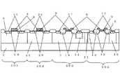
図1は本発明の第1の実施例を表す模式断面図である。本実施例ではN型半導体基板7に、低電圧駆動用の低耐圧のMOSトランジスタ501、502と、高電圧駆動用の高耐圧のMOSトランジスタ503、504を集積化している。
FIG. 1 is a schematic sectional view showing a first embodiment of the present invention. In this embodiment, low breakdown
低耐圧NMOSトランジスタ501は、半導体集積回路装置の中の低電圧用信号処理領域内のP型ウェル領域5内に形成された、従来と同様の構造を有する低電圧駆動用であり、ゲート電極6、ゲート絶縁膜9、ドレイン/ソース領域の一部を構成しドレイン/ソース端子を取り出すためのN型高濃度不純物領域17、ドレイン/ソース領域の一部を構成しドレイン/ソース間の電界緩和を目的とした第1のN型低濃度不純物領域18とからなる。
The low-breakdown-
また、低耐圧PMOSトランジスタ502は、同じく半導体集積回路装置の中の低電圧用信号処理領域内のN型ウェル領域21内に形成された、従来と同様の構造の低電圧駆動用であり、ゲート電極6、ゲート絶縁膜9、ドレイン/ソース領域の一部を構成しドレイン/ソース端子を取り出すためのP型高濃度不純物領域23、ドレイン/ソース領域の一部を構成しドレイン/ソース間の電界緩和を目的としたP型低濃度不純物領域20とからなる。
The low breakdown
また、第1の高耐圧NMOSトランジスタ503は、半導体集積回路装置の中の高電圧用信号処理領域内のP型ウェル領域5内に形成された高電圧駆動用であり、ゲート電極6、ゲート絶縁膜9、ドレイン/ソース領域の一部を構成しドレイン/ソース端子を取り出すためのN型高濃度不純物領域17、ドレイン/ソース領域の一部を構成しドレイン/ソース間の電界緩和を目的とした第2のN型低濃度不純物領域19、ゲート絶縁膜より厚い膜厚を有しゲート/ドレイン間の電界緩和を目的とした第2のN型低濃度不純物領域19上に形成された厚い絶縁膜13、第2のN型低濃度不純物領域19の一部を含む領域及びN型高濃度不純物領域17の下方に、P型ウェル領域5よりは浅く形成された第3のN型低濃度不純物領域14とからなり、高電圧信号処理回路に使用する。
The first high
また、第2の高耐圧NMOSトランジスタ504は、P型ウェル領域5内に形成された高電圧駆動用であり、高電圧の電源端子と最低電位であるグラウンド端子との間に設置し、外部から侵入する静電気ノイズ保護用素子として使用するが、本実施例においては第1の高耐圧NMOSトランジスタ503と同じ構造である。
The second high-breakdown-
また図示はしないが、半導体集積回路装置の中の高電圧用信号処理領域内のN型ウェル領域内に形成した高電圧駆動用の高耐圧PMOSトランジスタも存在し、ゲート電極、ゲート絶縁膜、ドレイン/ソース領域の一部を構成しドレイン/ソース端子を取り出すためのP型高濃度不純物領域、ドレイン/ソース領域の一部を構成しドレイン/ソース間の電界緩和を目的としたP型低濃度不純物領域、及びゲート/ドレイン間の電界緩和を目的としたP型低濃度不純物領域上に形成するゲート絶縁膜より厚い絶縁膜とから構成される。 Although not shown, there is also a high-voltage driving high-voltage PMOS transistor formed in an N-type well region in a high-voltage signal processing region in a semiconductor integrated circuit device, and includes a gate electrode, a gate insulating film, a drain / P-type high-concentration impurity region for forming a part of the source region and taking out the drain / source terminal, and P-type low-concentration impurity for forming an electric field between the drain and source by forming a part of the drain / source region And an insulating film thicker than the gate insulating film formed on the P-type low-concentration impurity region for the purpose of relaxing the electric field between the gate and the drain.
また図2は、上記各MOSトランジスタ素子の回路上の代表的な役割の例を表す回路図の一部である。先に述べたように、電源端子106と、最低電位となるグラウンド端子105の間に印加する電圧は近年高電圧化しており、その信号処理は第1の高耐圧NMOSトランジスタ503と高耐圧PMOSトランジスタ505とで構成した回路によって行う。
FIG. 2 is a part of a circuit diagram showing an example of a typical role of each MOS transistor element on the circuit. As described above, the voltage applied between the
また、その電源端子106とグラウンド端子105間の静電気ノイズから内部回路を保護するための静電気ノイズ用保護素子は、本実施例では第1の高耐圧NMOSトランジスタと同じ構造の第2の高耐圧NMOSトランジスタ504を使用し、電源端子106にドレイン端子を接続し、グラウンド端子105にソース端子及びゲート端子を接続するゲートオフ構成を取り、静電気ノイズが侵入した場合のみアバランシェ降伏によりドレイン端子からグラウンド端子にその静電気ノイズを逃がし、内部回路を静電気ノイズから守る役割を担う。
In addition, in the present embodiment, the protection element for electrostatic noise for protecting the internal circuit from electrostatic noise between the
もし高電圧信号処理回路において出力端子107がある場合は、その出力端子107とグラウンド端子105間の静電気ノイズについては、回路上出力端子107とグラウンド端子105間に設定されている第1の高耐圧NMOSトランジスタ503がそのまま静電気ノイズ保護素子としての役割を兼用してもよい。もしこの第1の高耐圧NMOSトランジスタの回路上小さいサイズで設定されているなどして、静電気ノイズに対する耐性が低い場合は、保護素子として並列にチャネル幅を静電気ノイズに基づく電流を充分許容できるサイズに大きく設定した高耐圧NMOSトランジスタを別途専用に設けてもよい。その場合は出力端子107にドレイン端子を接続し、グラウンド端子にソース端子及びゲート端子を接続するゲートオフ構成で実現する。
If there is an
さらに、本実施例の半導体集積回路装置では高電圧から低電圧を生成し、その低電圧で信号処理をしたのち、その結果を低電圧出力する機能を有するが、その様子も図2で模式的に表している。すなわち、電源端子106とグラウンド端子105間に印加される高電圧を、例えば分圧回路103で抵抗分割をするなどにより降圧して電源端子106と内部低電圧用グラウンド端子112の間に低電圧出力し、低電圧用信号処理領域内の第1の低耐圧NMOSトランジスタ501と低耐圧PMOSトランジスタ502で信号処理を行い、その結果を低電圧出力端子113より出力する。
Furthermore, the semiconductor integrated circuit device of this embodiment has a function of generating a low voltage from a high voltage, performing signal processing at the low voltage, and outputting the result at a low voltage. This is also schematically shown in FIG. It represents. That is, a high voltage applied between the
この低電圧出力端子113と内部低電圧用グラウンド端子112間や、電源端子106と内部低電圧用グラウンド端子112間に、外部から静電気ノイズを受ける場合の保護法方は図示しないが、低電圧用保護素子を別途用意し各端子間に従来の方法で設置する。
Although a protection method in the case of receiving electrostatic noise from the outside between the low
次に図1の本実施例の構造で、N型半導体基板を採用しながら、30V以上の耐圧を保ち、外部からの静電気ノイズなどによる発熱破壊を防ぐことができる高耐圧NMOSトランジスタの実現方法について説明する。 Next, a method for realizing a high breakdown voltage NMOS transistor having the structure of the present embodiment shown in FIG. 1 and capable of maintaining a breakdown voltage of 30 V or more and preventing a heat generation damage due to external static noise while adopting an N-type semiconductor substrate. explain.
図1においてN型半導体基板7はリンを3×10¹⁴/cm3から8×1014/cm3の濃度で含有する基板を選ぶ。30V以上の高耐圧NMOSトランジスタを作製するために薄い不純物濃度領域による電界緩和層を形成するためにはこの程度に薄い不純物濃度を有する半導体基板の採用が望ましい。
In FIG. 1, a substrate containing phosphorus at a concentration of 3 × 10 14 / cm 3 to 8 × 10 14 / cm 3 is selected as the N-
次に、P型ウェル領域5は、ここではどのNMOSトランジスタでも同一の条件のものを使用しており、ホウ素もしくはBF2のP型不純物を8×10¹⁵/cm3から4×1016/cm3の間の値で、拡散深さが半導体基板表面より7μmから10μmになるように形成している。このようにP型ウェル領域5の不純物濃度を比較的薄くしているのも、後に説明する高耐圧NMOSトランジスタの第3のN型低濃度不純物領域14の濃度の調整範囲を広げるためであり、30V以上の高耐圧NMOSトランジスタの作製を優先するためである。
Next, the P-
また、このような不純物濃度のP型ウェル領域を低耐圧NMOSトランジスタ501に採用する場合、その最小ゲート長は、パンチスルー現象による耐圧の低下などの短チャネル効果を考慮し、1.0μmとすることが望ましい。その場合、低耐圧NMOSトランジスタは、特に第1のN型低濃度不純物領域の構造の最適化により12Vまでの電圧信号処理に対応させることができる。すなわち、本実施例1はゲート長が1.0μm以上の廉価なプロセスで、低電圧の出力電圧が12Vまで要求される半導体集積回路装置への採用に対して好適であるといえる。
Further, when a P-type well region having such an impurity concentration is employed in the low breakdown
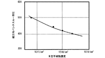
本発明で特徴的な第3のN型低濃度不純物領域14もしくは以下で説明する第4のN型低濃度不純物領域15は、N型不純物である砒素を2×10¹⁶/cm3から2×1017/cm3の不純物濃度で、半導体基板表面より2μmから3.5μmの深さに形成する。この条件設定の際に留意すべきことは、第3、4のN型低濃度不純物領域は不純物濃度が薄く拡散深さが浅くなると、静電気ノイズによる発熱破壊耐性が低下していく事に対し、不純物濃度が濃く拡散深さが深くなると、第3、4のN型低濃度不純物領域に高電圧をかけた際に第3、4のN型低濃度不純物領域とN型半導体基板の間でパンチスルー現象により縦方向の耐圧低下を引き起こしてしまうというトレードオフ関係である。従って、要求仕様に合わせて第3、4のN型低濃度不純物領域の形成条件を選ぶ必要がある。 The third N-type low-concentration impurity region 14 or the fourth N-type low-concentration impurity region 15 to be described below, which is characteristic of the present invention, contains arsenic as an N-type impurity from 2 × 10 16 / cm 3 to 2 ×. The semiconductor substrate is formed to a depth of 2 μm to 3.5 μm with an impurity concentration of 10 17 / cm 3 . What should be noted when setting these conditions is that the third and fourth N-type low-concentration impurity regions have a low impurity concentration and a small diffusion depth, and the resistance to heat breakdown due to electrostatic noise decreases. When the impurity concentration is high and the diffusion depth is deep, punching occurs between the third and fourth N-type low concentration impurity regions and the N-type semiconductor substrate when a high voltage is applied to the third and fourth N-type low concentration impurity regions. This is a trade-off relationship that the vertical breakdown voltage drop is caused by the through phenomenon. Therefore, it is necessary to select the formation conditions of the third and fourth N-type low concentration impurity regions in accordance with the required specifications.
例えば、第3、4のN型低濃度不純物領域とN型半導体基板の間の縦方向耐圧に関し、第3、4のN型不純物として砒素をイオン注入し、1170℃において20時間程度の熱処理で拡散、形成した場合の、不純物濃度に対する縦方向耐圧の関係を表す図3によると、6×10¹⁶/cm3のN型不純物濃度を形成する事で50V程度の縦方向耐圧を得ることが出来る。さらに、この条件では、3kV以上のESD破壊耐量(ヒューマン・ボディ・モデル)を達成することができ、結果として40Vの電源電圧仕様を満たす半導体集積回路装置を実現できる。 For example, regarding the vertical breakdown voltage between the third and fourth N-type low-concentration impurity regions and the N-type semiconductor substrate, arsenic is ion-implanted as the third and fourth N-type impurities, and heat treatment is performed at 1170 ° C. for about 20 hours. According to FIG. 3 showing the relationship of the vertical breakdown voltage with respect to the impurity concentration in the case of diffusion and formation, a vertical breakdown voltage of about 50 V can be obtained by forming an N-type impurity concentration of 6 × 10 16 / cm 3. . Furthermore, under these conditions, an ESD breakdown tolerance (human body model) of 3 kV or higher can be achieved, and as a result, a semiconductor integrated circuit device that satisfies the power supply voltage specification of 40 V can be realized.
このようにして、第1の実施例においては、ESDによる発熱破壊基準をクリアしながら、60V弱の耐圧までを実現することが出来、30Vから50Vまでの入力電源電圧仕様に対し対応可能な半導体集積回路装置を提供することができる。 In this way, in the first embodiment, it is possible to achieve a withstand voltage of less than 60V while clearing the heat generation destruction standard by ESD, and it is possible to meet the input power supply voltage specification from 30V to 50V. An integrated circuit device can be provided.
さらに本実施例では、第4のN型低濃度不純物として砒素を用いる事で、上記P型ウェル領域及び第3、4のN型低濃度不純物領域の両者の拡散熱処理を、1170℃における20時間程度の条件を用いた一括処理形成で実現できている。これは第3、4のN型低濃度不純物として拡散係数の高いリンや拡散係数の低いアンチモンの採用ではいずれも実現不可能であり、本発明の条件を選ぶことでN型半導体基板を用いながら、高電圧に耐えうる半導体集積回路装置を、従来の高温熱処理条件を踏襲しながら工期の長期化を伴わずに作製することを可能としている。 Furthermore, in this embodiment, by using arsenic as the fourth N-type low concentration impurity, diffusion heat treatment of both the P-type well region and the third and fourth N-type low concentration impurity regions is performed at 1170 ° C. for 20 hours. It can be realized by batch processing formation using a certain degree of condition. This cannot be realized by using phosphorus having a high diffusion coefficient or antimony having a low diffusion coefficient as the third and fourth N-type low-concentration impurities, and using an N-type semiconductor substrate by selecting the conditions of the present invention. Therefore, it is possible to manufacture a semiconductor integrated circuit device capable of withstanding high voltage without increasing the construction period while following conventional high-temperature heat treatment conditions.
一方、第3、4のN型低濃度不純物領域以外の条件については、高耐圧NMOSトランジスタのドレイン/ソース間耐圧を確保するために、第2のN型低濃度不純物領域19を、不純物としてリンを用い1×1017/cm3から1×1018/cm3までの間の不純物濃度で形成する。またこのN型低濃度不純物領域19の上にゲート絶縁膜よりも厚い絶縁膜13を形成している。この厚い絶縁膜はゲート/ドレイン間の電界緩和効果に対して有効であり、素子分離のためのLOCOS絶縁膜と兼用してもよい。これらの構造については従来と同様の条件を採用して構わない。
On the other hand, for conditions other than the third and fourth N-type low-concentration impurity regions, the second N-type low-
次に、本発明の第2の実施例を図4に基づいて説明する。図4は本発明の第2の実施例の模式断面図であり、低耐圧NMOSトランジスタ501、低耐圧PMOSトランジスタ502、第1の高耐圧NMOSトランジスタ503、第2の高耐圧NMOSトランジスタ504のそれぞれの断面構造を示しており、第1の実施例からさらに構造の変更を行っている。このうち第1の実施例と異なるのは第2の高耐圧NMOSトランジスタ504のドレイン構造であり、第2の実施例ではこの第2の高耐圧トランジスタ504は、第1の高耐圧NMOSトランジスタ503でドレイン領域に設ける深い拡散として採用している第3のN型低濃度不純物領域14を、第4のN型低濃度不純物領域15に替えている。
Next, a second embodiment of the present invention will be described with reference to FIG. FIG. 4 is a schematic cross-sectional view of the second embodiment of the present invention. Each of the low breakdown
この第4のN型低濃度不純物領域15の拡散深さは、第3のN型低濃度不純物領域14よりも深く、P型ウェル領域5と同程度の深さであり、P型ウェル領域5との2重拡散構造はとっていない。そのため第4のN型低濃度不純物領域15の底面はN型半導体基板7と接している。N型半導体基板は通常最も高電位となる電源電圧を印加するので、このN型半導体基板と接する第4のN型低濃度不純物領域15及びそれにつながる第2の高耐圧NMOSトランジスタのドレイン端子は高電位となる電源電圧と導通しており、ドレイン端子と電源端子が同電位となるような回路上の使われ方をする高耐圧NMOSトランジスタ全てに採用することが出来る。半導体集積回路装置上、このような使用形態を確実に必要とする例は、図2の504に示す、電源端子に外部から侵入する静電気ノイズから半導体集積回路素子を保護する静電気ノイズ保護用素子である。すなわち、電源端子106に第2の高耐圧N型トランジスタのドレイン端子を結線し、グラウンド端子105にソース端子及びゲート端子を結線するオフ構成を取り、静電気ノイズが侵入した場合のみアバランシェ破壊によりドレイン端子からグラウンド端子にその静電気ノイズを逃がす役割を担う。
The diffusion depth of the fourth N-type low-concentration impurity region 15 is deeper than that of the third N-type low-concentration impurity region 14 and the same depth as the P-
ところで、図4の断面図中の第1の高耐圧NMOSトランジスタ503のように、P型ウェル領域5内に半導体基板7から一定の距離だけ浅くした深さでドレイン領域に形成する第3のN型低濃度不純物領域14は、先に述べたようにその不純物濃度と半導体基板表面からの拡散深さに対し、静電気ノイズなどによる発熱耐性と、パンチスルー現象に起因する縦方向耐圧低下のトレードオフ関係に基づき決める必要があり、条件設定の幅が狭い。一方、第2の高耐圧NMOSトランジスタ504は第4のN型低濃度不純物領域15とN型半導体基板7が接しており、先のトレードオフ関係の後者にあたる縦方向耐圧を懸念する必要がない。従って、静電気ノイズなどによる発熱耐性のみで構造を最適化すればよく、所要面積縮小効果とそれに伴う低コスト化が実現できるという利点がある。
By the way, like the first high breakdown
具体的には、第2の高耐圧NMOSトランジスタ504は、ドレイン領域に形成するN型低濃度不純物領域がN型半導体基板と接しているため、静電気ノイズ耐性で必要とされるドレイン端子につながるN型拡散領域の体積が、第1の高耐圧NMOSトランジスタ503に比べ著しく大きい。従って第1の高耐圧NMOSトランジスタと同等のESD発熱耐量を得るために、ESD発熱耐量に比例して必要とされるチャネル幅を第1の高耐圧NMOSトランジスタ503に比べ2/3以下に縮小することが出来る。
Specifically, in the second high breakdown
さらに第2の実施例では第2の高耐圧NMOSトランジスタ504の採用により、回路構成によっては、N型半導体基板を採用した50V以上の高電圧を要求される半導体集積回路装置の実現が可能となる。
Further, in the second embodiment, the use of the second high
まず、第2の高耐圧NMOSトランジスタ504自体は、パンチスルー現象に起因する縦方向耐圧の制約がないので、ドレイン/ソース間電圧の高耐圧化に対して第2のN型低濃度不純物領域19のさらなる低濃度化とサイズの伸張により、高電圧による空乏層の伸びを確保することで50V以上の高電圧化に対する対応が可能となる。
First, since the second high breakdown
一方、高電圧信号処理の内部回路については、第1の高耐圧NMOSトランジスタ503もしくは高耐圧PMOSトランジスタ505をカスコード接続などして高電圧を分圧するように回路設定をすることで1つの素子あたりの印加電圧を緩和し、50V以上の高電圧での回路動作を実現することが可能となる。
On the other hand, with respect to the internal circuit of the high voltage signal processing, by setting the circuit so as to divide the high voltage by cascode connection or the like of the first high
次に図4の本発明の第2の高耐圧NMOSトランジスタ504の構造について説明する。第2の高耐圧NMOSトランジスタのゲート電極6、ゲート絶縁膜9、第2のN型低濃度不純物領域19、第2のN型低濃度不純物領域19上のゲート絶縁膜よりも厚い絶縁膜13の基本的な構造は第1の高耐圧NMOSトランジスタ503と同じである。
Next, the structure of the second high
一方、第1の高耐圧NMOSトランジスタ503と異なる第4のN型低濃度不純物領域15は、P型ウェル領域5が形成されない領域を設定し、そこにN型不純物のリンを8×10¹⁵/cm3から4×1016/cm3の間の値で半導体基板表面から7μmから10μmまでの拡散深さに形成している。すなわち、低耐圧もしくは高耐圧PMOSトランジスタを形成するNウェル領域21と兼用してもよい。このような構成にすることで、特別な工程追加が必要なくなり、プロセスコストの増加を伴わずに第4のN型低濃度不純物領域15を形成できる。
On the other hand, the fourth N-type low-concentration impurity region 15 different from the first high-breakdown-
また、第4のN型低濃度不純物領域15をN型ウェル領域21と兼用することで、セルフアラインツインウェルプロセスを採用することができる。こうすることで第4のN型低濃度不純物領域15をP型ウェル領域5と正確に隣接して形成させることができ、また第4のN型低濃度不純物領域とP型ウェル領域との相互拡散によりPN接合位置が移動することが無くなるので、第3のN型低濃度不純物領域14と異なり、第4のN型低濃度不純物領域15の横方向の拡散広がりを抑制することができる。つまり実施例2の第2の高耐圧NMOSトランジスタにおいては、先に述べたように静電気ノイズ吸収のためのチャネル幅を第1の高耐圧NMOSトランジスタより短くするとともに、第4のN型不純物領域15の平面サイズをも第3のN型低濃度不純物領域14よりも縮小できるというコスト低減の利点を併せ持つ。
Further, by using the fourth N-type low concentration impurity region 15 also as the N-
次に、本発明の第3の実施例について図5に基づいて説明する。図5は本発明の第3の実施例の模式断面図であり、低耐圧NMOSトランジスタ501、低耐圧PMOSトランジスタ502、第1の高耐圧NMOSトランジスタ503、第2の高耐圧NMOSトランジスタ504のそれぞれの断面構造を示しており、第2の実施例からさらに構造の追加を行っている。このうち第2の実施例と異なるのはP型ウェル領域の一部の不純物濃度である。
Next, a third embodiment of the present invention will be described with reference to FIG. FIG. 5 is a schematic cross-sectional view of the third embodiment of the present invention. Each of the low breakdown
まず第1の高耐圧NMOSトランジスタ503については、第1、2の実施例と同様にドレイン領域に深い拡散領域である第3のN型低濃度不純物領域14を設けているが、そのN型低濃度不純物領域14の下のN型半導体基板7との間にある第1のP型ウェル領域5は第2の実施例と同じであるものの、第3のN型低濃度不純物領域14に隣接している第2のP型ウェル領域8は、第1のP型ウェル領域5よりP型不純物濃度が濃くなっている。
The first high breakdown
この第2のP型ウェル領域8と第3のN型低濃度不純物領域14は、第1のP型ウェル領域5と第1のN型ウェル領域21と同様に、後に述べるセルフアラインツインウェルプロセスで形成しているため、第2のP型ウェル領域8と第3のN型低濃度不純物領域14は正確に接合位置が一致し、不純物のイオン注入時の形成位置からのずれを生じない。このため、第3のN型低濃度不純物領域14の横方向の拡散広がりとそれに伴う第1の高耐圧NMOSトランジスタの所要面積の増大を抑制し、半導体集積回路装置のコスト低減に寄与することが出来る。
The second P-
さらに、低耐圧NMOSトランジスタ501と第2の高耐圧NMOSトランジスタ504のP型ウェル領域も第2のP型ウェル領域8を採用し、P型不純物濃度が濃くなっている事が第2の実施例と異なっている。このとき、第2のP型ウェル領域8とN型ウェル領域21もセルフアライン的に形成されており、接合位置のずれは生じない。この第2のP型ウェル領域8は、ホウ素もしくはBF2のP型不純物を5×10¹⁶/cm3から2×1017/cm3の間の値で形成し第1のP型ウェル領域に対し濃い不純物濃度に保っている。
Further, the P-type well region of the low breakdown
このような高い不純物濃度のP型ウェル領域を低耐圧NMOSトランジスタ501に採用する場合、第1のP型ウェル領域5を採用する場合に比べて、パンチスルー現象による耐圧の低下などの短チャネル効果が抑制され、その最小ゲート長は、0.5μmとすることができる。その場合、低耐圧NMOSトランジスタは、特に第1のN型低濃度不純物領域の構造の最適化により6Vまでの電圧信号処理に対応させることができる。すなわち、本実施例3は、他の実施例に比べて微細のルールを採用し所要面積の低減を図りながら、出力電圧6V以下の半導体集積回路装置において低コスト化を促進できる、という効果がある。
When such a high impurity concentration P-type well region is employed in the low-breakdown-
次に、本発明の第1の実施例を実現するための製造方法を、図7から図9の工程フローを示す断面図を用いて説明する。
まず、リンを3×10¹⁴/cm3から8×1014/cm3の濃度で含有するN型半導体基板7を用意し、そのN型半導体基板7上に100から500Åの厚さのシリコン酸化膜24を熱酸化法で形成し、さらにそのシリコン酸化膜24上にLPCVD(Low Pressure Chemical Vapor Deposition)法により300から1500Åの厚さのシリコン窒化膜25を堆積する(図7(1))。
Next, a manufacturing method for realizing the first embodiment of the present invention will be described with reference to cross-sectional views showing the process flow of FIGS.
First, an N-
次に、N型ウェル領域形成予定領域のシリコン窒化膜を、フォトリソグラフィ技術及びドライエッチング技術により除去し、露出したシリコン酸化膜を通してシリコン窒化膜及びフォトレジストをマスクとし、3×10¹²/cm2から3×1013/cm2程度のドーズ量にてN型不純物のリンをイオン注入法により注入し、リンが注入された領域21を形成し、その後フォトレジストを剥離する(図7(2))。
Next, the silicon nitride film in the region where the N-type well region is to be formed is removed by photolithography technology and dry etching technology, and the silicon nitride film and photoresist are used as a mask through the exposed silicon oxide film to 3 × 10 12 / cm 2. N-type impurity phosphorus is implanted by ion implantation at a dose of about 3 × 10 13 / cm 2 to form a
次に熱酸化法により、残された窒化膜をマスクとして選択的にN型ウェル領域形成予定領域に1000から3000Åのシリコン酸化膜を形成する。次に、窒化膜を除去したのち、先の1000から3000Åのシリコン酸化膜をマスクとして、N型ウェル領域以外のP型ウェル領域形成予定領域に2×10¹²/cm2から1×1013/cm2程度のドーズ量のホウ素もしくはBF2のP型不純物5をイオン注入法によりセルフアラインに注入する(図7(3))。
以上のようなツインウェルプロセスにより、1つのフォトマスクのみでP型ウェル領域とN型ウェル領域を正確に隣接して形成することが出来る。
Next, a silicon oxide film having a thickness of 1000 to 3000 nm is selectively formed in the region where the N-type well region is to be formed by thermal oxidation using the remaining nitride film as a mask. Next, after removing the nitride film, the silicon oxide film having a thickness of 1000 to 3000 mm is used as a mask to form a P-type well region formation region other than the N-type well region at 2 × 10 12 / cm 2 to 1 × 10 13 / A boron or BF 2 P-
By the twin well process as described above, the P-type well region and the N-type well region can be formed precisely adjacent to each other with only one photomask.
次に、第3のN型低濃度不純物領域形成予定領域に、フォトレジストをマスクとしシリコン酸化膜を通して、8×10¹²/cm2から7×1013/cm2程度のドーズ量のN型不純物の砒素をイオン注入法により注入し、砒素が注入された領域14を形成し、その後フォトレジストを剥離する(図8(1))。 Next, an N-type impurity having a dose of about 8 × 10 12 / cm 2 to 7 × 10 13 / cm 2 is formed in the third N-type low-concentration impurity region formation region through a silicon oxide film using a photoresist as a mask. The arsenic is implanted by an ion implantation method to form a region 14 into which arsenic has been implanted, and then the photoresist is stripped (FIG. 8A).
次に、1170℃から1200℃の温度で15時間から20時間程度の時間の熱処理でこれらのN型及びP型不純物を同時に拡散させ、所望の拡散深さのP型ウェル領域5、N型ウェル領域21、第3のN型低濃度不純物領域14を得る(図8(2))。
Next, these N-type and P-type impurities are simultaneously diffused by heat treatment at a temperature of 1170 ° C. to 1200 ° C. for about 15 hours to 20 hours, so that a P-
以上の工程を経ることにより、N型不純物のリンからなる8×10¹⁵/cm3から4×1016/cm3の不純物濃度の値を有する半導体基板表面より7μmから10μmの拡散深さのN型ウェル領域と、ホウ素もしくはBF2からなりP型不純物濃度が8×1015/cm3から4×1016/cm3の間の値を有する半導体基板表面より7μmから10μmの拡散深さのP型ウェル領域と、砒素からなり2×1016/cm3から1×1018/cm3の不純物濃度の値を有する半導体基板表面より2μmから3.5μmの深さの第3のN型低濃度不純物領域を形成できる。 Through the above steps, N having a diffusion depth of 7 μm to 10 μm from the surface of the semiconductor substrate having an impurity concentration of 8 × 10 15 / cm 3 to 4 × 10 16 / cm 3 made of N-type impurity phosphorus. P having a diffusion depth of 7 μm to 10 μm from the well region and the surface of the semiconductor substrate made of boron or BF 2 and having a P-type impurity concentration between 8 × 10 15 / cm 3 and 4 × 10 16 / cm 3 A third N-type low concentration of 2 μm to 3.5 μm from the surface of the semiconductor substrate having an impurity concentration value of 2 × 10 16 / cm 3 to 1 × 10 18 / cm 3 made of arsenic Impurity regions can be formed.
本発明では1100℃以上の高温長時間熱処理は、セルフアライン的に注入したP型ウェル領域とN型ウェル領域の不純物の一括拡散形成だけでなく、ここに第3のN型低濃度不純物領域を形成するための不純物拡散も兼用させている。その際、N型不純物としては砒素を選び、P型ウェル領域を形成するホウ素もしくはBF2と砒素との拡散係数の違いを利用して、一度の熱処理でP型ウェル領域は深く、第3のN型不純物領域は浅く拡散させることにより、P型ウェル領域の中に第3のN型不純物領域を2重拡散構造で形成できるよう調整している。 In the present invention, the high-temperature long-time heat treatment at 1100 ° C. or higher is not limited to the collective diffusion formation of impurities in the P-type well region and the N-type well region implanted in a self-aligned manner. Impurity diffusion for forming is also used. At this time, arsenic is selected as the N-type impurity, and the difference in diffusion coefficient between boron or BF 2 and arsenic that forms the P-type well region is utilized to deepen the P-type well region by one heat treatment. The N-type impurity region is shallowly diffused so that the third N-type impurity region can be formed in the P-type well region with a double diffusion structure.
このような本発明の方法で第3のN型不純物注入量を適宜調節することで、図3のようなプロセス条件と耐圧の関係を得ることができ、N型半導体基板を採用していながら様々な入力電圧仕様の半導体集積回路装置に対応できることが明らかになった。 By appropriately adjusting the third N-type impurity implantation amount by the method of the present invention as described above, the relationship between the process conditions and the breakdown voltage as shown in FIG. 3 can be obtained, and variously adopted while employing the N-type semiconductor substrate. It has become clear that it can be applied to a semiconductor integrated circuit device with a wide input voltage specification.
次に、一旦全てのシリコン酸化膜を半導体基板表面から除去した後、100から500Åの厚さのシリコン酸化膜24を熱酸化法で形成し、さらにそのシリコン酸化膜24上にLPCVD法により300から1500Åの厚さのシリコン窒化膜25を堆積する。次に第2のN型低濃度不純物領域を形成するために、フォトリソグラフィ技術及びドライエッチング技術によりシリコン窒化膜を除去し、シリコン窒化膜及びフォトレジストをマスクとし、シリコン酸化膜を通して、1×10¹²/cm2から7×1012/cm2程度のドーズ量のN型不純物のリン19をイオン注入法により注入し、その後フォトレジストを剥離する(図8(3))。
Next, after all the silicon oxide film is once removed from the surface of the semiconductor substrate, a
この第2のN型低濃度不純物領域は、高耐圧NMOSトランジスタのドレイン/ソース間耐圧を調整するために設定するもので、1×1017/cm3から1×1018/cm2程度のドーズ量とする事が好ましいが、プロセスコスト削減のために素子分離のためのチャネルストッパー用不純物注入と兼用して形成しても構わない(図示せず)。 This second N-type low-concentration impurity region is set for adjusting the drain / source breakdown voltage of the high breakdown voltage NMOS transistor and has a dose of about 1 × 10 17 / cm 3 to 1 × 10 18 / cm 2. However, it may be formed in combination with channel stopper impurity implantation for element isolation in order to reduce process costs (not shown).
次に熱酸化法により、残された窒化膜をマスクとして選択的に第2のN型低濃度不純物領域形成予定領域に6000から12000Åのシリコン酸化膜を形成し、その後シリコン窒化膜を剥離する(図9(1))。この6000から12000Åの熱酸化膜は、高耐圧NMOSトランジスタのゲート/ドレイン間の電界緩和効果を狙いゲート絶縁膜より厚くした絶縁体であるが、同時に素子外分離領域のLOCOS(Local Oxidation Of Silicon)絶縁膜と兼用して形成することで、プロセスコストの削減を図ることができる。 Next, a silicon oxide film having a thickness of 6000 to 12000 nm is selectively formed in the second N-type low-concentration impurity region formation region by thermal oxidation using the remaining nitride film as a mask, and then the silicon nitride film is peeled off ( FIG. 9 (1)). This thermal oxide film of 6000 to 12000 mm is an insulator that is thicker than the gate insulating film for the purpose of reducing the electric field between the gate and drain of the high breakdown voltage NMOS transistor. At the same time, the LOCOS (Local Oxidation Of Silicon) in the isolation region outside the element is used. By forming the insulating film also, the process cost can be reduced.
次に、必要に応じてMOSトランジスタの閾値電圧制御のためのチャネル不純物注入や各MOSトランジスタのゲート絶縁膜9形成を行ったあと、ゲート電極6を形成するために、2000から5000Åの多結晶シリコン膜を堆積し、1×10¹⁹/cm3以上の不純物濃度となるように、高濃度の不純物注入をイオン注入法、もしくは熱拡散法で行い、その後フォトリソグラフィ技術及びドライエッチング技術を用いて所望の形状に加工する(図9(2))。
Next, after performing channel impurity implantation for controlling the threshold voltage of the MOS transistor and forming the
次に、低耐圧NMOSトランジスタのドレイン/ソース間の電界緩和を目的とした第1のN型低濃度不純物領域18の形成、及び低耐圧PMOSトランジスタのドレイン/ソース間の電界緩和を目的としたP型低濃度不純物領域20の形成を行う。それぞれの条件は、所望の動作電圧に応じて決めるが、2×1012/cm2から2×1014/cm2程度のドーズ量のN型及びP型不純物の注入をイオン注入法で行う。
Next, the formation of the first N-type low-concentration impurity region 18 for the purpose of relaxing the electric field between the drain and source of the low breakdown voltage NMOS transistor and the purpose of reducing the electric field between the drain and source of the low breakdown voltage PMOS transistor are described. The type low
次に、低耐圧NMOSトランジスタ及び高耐圧NMOSトランジスタのドレイン/ソース端子を取り出すためのN型高濃度不純物領域17の形成、及び低耐圧NMOSトランジスタ及び高耐圧NMOSトランジスタのドレイン/ソース端子を取り出すためのP型高濃度不純物領域23の形成を、2×1015/cm2以上のドーズ量のイオン注入法で注入することによって行う(図9(3))。
Next, an N-type high-
次に図示しないが、全体に酸化膜からなる絶縁膜を堆積し、それぞれのMOSトランジスタの端子電極を取り出すために所定の位置にドライエッチング技術を用いてコンタクトホールを形成し、次にそれらの端子に電位を与えるための金属配線を形成するために、アルミからなる金属膜をスパッタリング法で堆積した後、ドライエッチング技術で加工形成を施す。 Next, although not shown in the figure, an insulating film made of an oxide film is deposited on the entire surface, and contact holes are formed at predetermined positions using a dry etching technique in order to take out the terminal electrodes of the respective MOS transistors. In order to form a metal wiring for applying a potential to the metal, a metal film made of aluminum is deposited by a sputtering method and then processed by a dry etching technique.
以上のような第1の実施例の製造方法とすることにより、N型半導体基板を用いながら、30V以上の耐圧と静電気ノイズなどによる発熱破壊耐量の確保を両立した高耐圧NMOSトランジスタを有する半導体集積回路を作製することができる。 By using the manufacturing method of the first embodiment as described above, a semiconductor integrated circuit having a high breakdown voltage NMOS transistor that achieves both a breakdown voltage of 30 V or more and a heat breakdown resistance due to electrostatic noise etc. while using an N-type semiconductor substrate. A circuit can be fabricated.
次に、本発明の第2の実施例を実現するための製造方法を、図10から12の工程フローを示す断面図を用いて説明する。
まず、リンを3×10¹⁴/cm3から8×1014/cm3の濃度で含有するN型半導体基板7に対し、熱酸化法によるシリコン酸化膜24の形成、LPCVD法によるシリコン窒化膜25の堆積を行う事は第1の実施例と同様である(図10(1))。
Next, a manufacturing method for realizing the second embodiment of the present invention will be described with reference to cross-sectional views showing the process flow of FIGS.
First, a
次に、N型ウェル領域形成予定領域のシリコン窒化膜を除去し、露出したシリコン酸化膜を通して、3×10¹²/cm2から3×1013/cm2程度のドーズ量のN型不純物リンをイオン注入法により注入し、その後フォトレジストを剥離する(図10(2))。ここで形成するN型ウェル領域21は、低耐圧PMOSトランジスタ及び高耐圧PMOSトランジスタのみならず、第2の高耐圧NMOSトランジスタのドレイン領域15となるドレイン領域形成予定領域にも追加して行う事が第1の実施例と異なる。
Next, the silicon nitride film in the region where the N-type well region is to be formed is removed, and N-type impurity phosphorus having a dose amount of about 3 × 10 12 / cm 2 to 3 × 10 13 / cm 2 is passed through the exposed silicon oxide film. Implantation is performed by ion implantation, and then the photoresist is removed (FIG. 10 (2)). The N-
次に、熱酸化法により、N型ウェル領域形成予定領域に1000から3000Åのシリコン酸化膜を形成し、窒化膜を除去した後このシリコン酸化膜をマスクとして、2×10¹²/cm2から1×1013/cm2程度のドーズ量のホウ素もしくはBF2のP型不純物5をイオン注入法により注入する(図10(3))。
Next, a silicon oxide film having a thickness of 1000 to 3000 mm is formed in the N-type well region formation region by thermal oxidation, and after removing the nitride film, the silicon oxide film is used as a mask to 2 × 10 12 / cm 2 to 1 Boron or BF 2 P-
次に、第1の高耐圧NMOSトランジスタの第3のN型低濃度不純物領域形成予定領域をフォトレジストをマスクとしシリコン酸化膜を通して、8×10¹²/cm2から7×1013/cm2程度のドーズ量のN型不純物の砒素14をイオン注入法により注入する(図11(1))。 Next, the third N-type low-concentration impurity region formation planned region of the first high-breakdown-voltage NMOS transistor is used as a mask to pass through a silicon oxide film to about 8 × 10 12 / cm 2 to 7 × 10 13 / cm 2 An N-type impurity arsenic 14 having a dose of 1 is implanted by ion implantation (FIG. 11 (1)).
次に、1170℃から1200℃の温度で15時間から20時間程度の時間の熱処理でこれらのN型及びP型不純物を同じに拡散させ、所望の拡散深さのN型ウェル領域、第1のP型ウェル領域、第2のP型ウェル領域、第3のN型低濃度不純物領域を得る(図11(2))。 Next, these N-type and P-type impurities are diffused in the same manner by heat treatment at a temperature of 1170 ° C. to 1200 ° C. for about 15 hours to 20 hours, and the N-type well region having the desired diffusion depth, A P-type well region, a second P-type well region, and a third N-type low-concentration impurity region are obtained (FIG. 11 (2)).
このように、第1の高耐圧NMOSトランジスタと第2の高耐圧NMOSトランジスタのドレイン領域の深い拡散を作り分けるが、第2の高耐圧NMOSトランジスタの第4のN型低濃度不純物領域をN型ウェル領域と兼用することで、第1の実施例に対し製造工程の増加無く第2の実施例を実現することが出来る。 As described above, the deep diffusion of the drain regions of the first high breakdown voltage NMOS transistor and the second high breakdown voltage NMOS transistor is made differently, but the fourth N type low concentration impurity region of the second high breakdown voltage NMOS transistor is changed to the N type. By also using the well region, the second embodiment can be realized without increasing the number of manufacturing steps compared to the first embodiment.
以下、第2のN型低濃度不純物領域の形成(図11(3))、第2のN型低濃度不純物領域上の絶縁膜及び素子分離絶縁膜の形成(図12(1))、ゲート絶縁膜及びゲート電極の形成(図12(2))、低耐圧MOSトランジスタ及び高耐圧MOSトランジスタのドレイン/ソース領域の形成(図12(3))と、図示しないが、コンタクトホールや金属配線の形成等を経て、半導体集積回路装置を完成させる。 Hereinafter, formation of the second N-type low-concentration impurity region (FIG. 11 (3)), formation of the insulating film and element isolation insulating film on the second N-type low-concentration impurity region (FIG. 12 (1)), gate Formation of an insulating film and a gate electrode (FIG. 12 (2)), formation of drain / source regions of a low breakdown voltage MOS transistor and a high breakdown voltage MOS transistor (FIG. 12 (3)), and although not shown, contact holes and metal wiring A semiconductor integrated circuit device is completed through formation and the like.
以上のような第2の実施例の製造方法とすることにより、N型半導体基板を用いながら、30V以上、さらには回路構成の工夫により50V以上の耐圧と、静電気ノイズなどによる発熱破壊耐量の確保を両立した第1の高耐圧NMOSトランジスタに加え、電源端子とグラウンド端子の間の保護素子としてさらに所要面積を低減した第2の高耐圧NMOSトランジスタを有する半導体集積回路を作製することができる。 By using the manufacturing method of the second embodiment as described above, while using an N-type semiconductor substrate, it is possible to secure a breakdown voltage of 30 V or more, and further a breakdown voltage of 50 V or more by devising a circuit configuration, and a heat generation breakdown resistance due to electrostatic noise or the like. In addition to the first high-breakdown-voltage NMOS transistor that satisfies both requirements, a semiconductor integrated circuit having a second high-breakdown-voltage NMOS transistor with a further reduced area as a protective element between the power supply terminal and the ground terminal can be manufactured.
次に、本発明の第3の実施例を実現するための製造方法を、図13から15の工程フローを示す断面図を用いて説明する。
まず、第2の実施例と同様に、N型半導体基板に対するシリコン酸化膜、シリコン窒化膜の形成(図13(1))、N型ウェル領域形成予定領域のシリコン窒化膜を除去し、露出したシリコン酸化膜を通して、N型不純物リンをイオン注入法により注入し、その後フォトレジストを剥離する、N型ウェル領域形成のためのN型不純物注入(図13(2))、熱酸化法により、N型ウェル領域形成予定領域にシリコン酸化膜を形成し、窒化膜を除去した後このシリコン酸化膜をマスクとして、ホウ素もしくはBF2のP型不純物5をイオン注入法により注入する、第1のP型ウェル領域形成のためのP型不純物注入(図13(3))を行う。以上のような第1のセルフアラインツインウェルプロセスにより、1つのフォトマスクのみで第1のP型ウェル領域とN型ウェル領域を正確に隣接して形成することが出来る。
その後の図14(1)から(3)の工程が第3の実施例特有の製造方法となる。
Next, a manufacturing method for realizing the third embodiment of the present invention will be described with reference to cross-sectional views showing the process flow of FIGS.
First, as in the second embodiment, the silicon oxide film and silicon nitride film are formed on the N-type semiconductor substrate (FIG. 13A), and the silicon nitride film in the region where the N-type well region is to be formed is removed and exposed. N-type impurity phosphorus is implanted through the silicon oxide film by an ion implantation method, and then the photoresist is peeled off. N-type impurity implantation for forming an N-type well region (FIG. 13 (2)). A silicon oxide film is formed in the type well region formation planned region, and after removing the nitride film, a P-
The subsequent steps (1) to (3) in FIG. 14 are the manufacturing method unique to the third embodiment.
図13(3)に続けて、シリコン窒化膜25をLPCVD法により堆積し、第3のN型低濃度不純物領域形成予定領域のシリコン窒化膜をフォトリソグラフィ技術及びドライエッチング技術にて開口し、シリコン窒化膜及びフォトレジストをマスクとし露出したシリコン酸化膜を通して、8×10¹²/cm2から7×1013/cm2程度のドーズ量のN型不純物の砒素14をイオン注入法により注入し、その後フォトレジストを剥離する(図14(1))。
Continuing to FIG. 13 (3), a
次に熱酸化法により、残された窒化膜をマスクとして選択的に第3のN型低濃度不純物領域形成予定領域に1000から3000Åのシリコン酸化膜を形成する。その後、窒化膜を除去したのち、先の1000から3000Åのシリコン酸化膜をマスクとして、5×10¹²/cm2から2×1013/cm2程度のドーズ量のホウ素もしくはBF2のP型不純物をイオン注入法により注入する。この注入領域は第1のP型ウェル領域のP型不純物注入に加え、重ねてP型不純物を注入することで、第1のP型ウェル領域よりも不純物濃度の高い第2のP型ウェル領域8を形成している(図14(2))。また、第3のN型不純物領域形成予定領域上に加え、N型ウェル形成予定領域上にも1000から3000Å以上のシリコン酸化膜が残されたままなので、ここにP型不純物が侵入することはない。 Next, a silicon oxide film having a thickness of 1000 to 3000 nm is selectively formed in the region where the third N-type low-concentration impurity region is to be formed by thermal oxidation using the remaining nitride film as a mask. After removing the nitride film, boron or BF 2 P-type impurity having a dose of about 5 × 10 12 / cm 2 to 2 × 10 13 / cm 2 using the silicon oxide film of 1000 to 3000 mm as a mask. Are implanted by an ion implantation method. In this implantation region, in addition to the P-type impurity implantation of the first P-type well region, a second P-type well region having an impurity concentration higher than that of the first P-type well region is implanted by overlapping the implantation of the P-type impurity. 8 is formed (FIG. 14 (2)). In addition to the third N-type impurity region formation region, the silicon oxide film of 1000 to 3000 mm or more remains on the N-type well formation region, so that P-type impurities can penetrate into this region. Absent.
以上のような第2のセルフアラインツインウェルプロセスを採用することにより、第2のP型ウェル領域と第3のN型低濃度不純物領域も正確に隣接して形成することが出来る。 By adopting the second self-aligned twin well process as described above, the second P-type well region and the third N-type low-concentration impurity region can also be formed accurately adjacent to each other.
次に、1170℃・20時間程度の熱処理でこれらのN型及びP型不純物を拡散させ、所望の拡散深さのN型ウェル領域、第1のP型ウェル領域、第2のP型ウェル領域、第3のN型低濃度不純物領域を得る(図14(3))。 Next, these N-type and P-type impurities are diffused by heat treatment at 1170 ° C. for about 20 hours, and an N-type well region, a first P-type well region, and a second P-type well region having desired diffusion depths are diffused. Then, a third N-type low concentration impurity region is obtained (FIG. 14 (3)).
このとき、第2のP型ウェル領域とN型ウェル領域は、図14(2)のように隣接して形成し、そのまま拡散するので両者の接合位置が変わることはない。さらに第2のP型ウェル領域と第3のN型低濃度不純物領域も隣接して形成され、そのまま拡散するので両者の接合位置が変わることはない。そのため本実施例においてこのような製造工程を採用することにより、各不純物領域のサイズが変わることなく、高精度なサイズ及び位置規定が実現できる。 At this time, the second P-type well region and the N-type well region are formed adjacent to each other as shown in FIG. 14 (2) and diffused as they are, so that the junction position between them does not change. Further, the second P-type well region and the third N-type low-concentration impurity region are also formed adjacent to each other and diffused as they are, so that the junction position between them does not change. Therefore, by adopting such a manufacturing process in this embodiment, it is possible to realize highly accurate size and position definition without changing the size of each impurity region.
また、イオン注入法によって形成する第1のP型ウェル領域と第2のP型ウェル領域の重なり領域は、上記の高温長時間熱処理前においては、不純物濃度の薄い第1のP型ウェル領域の方が半導体基板表面から深くまで形成され、不純物濃度の濃い第2のP型ウェル領域の方が浅く形成されているため、2段階ステップ状の深さ方向濃度プロファイルが形成されるが、高温長時間熱処理により拡散した結果、このような深さ方向の濃度プロファイルの不均一性は解消される。 In addition, the overlapping region of the first P-type well region and the second P-type well region formed by the ion implantation method is the same as that of the first P-type well region having a low impurity concentration before the above high-temperature and long-time heat treatment. Since the second P-type well region having a higher impurity concentration is formed shallower than the surface of the semiconductor substrate, a two-step stepwise depth direction concentration profile is formed. As a result of diffusion by temporal heat treatment, such non-uniformity of the concentration profile in the depth direction is eliminated.
以上の工程を経ることにより、リンからなりN型不純物濃度が8×10¹⁵/cm3から4×1016/cm3の不純物濃度の値で、半導体基板表面より7μmから10μmまでの拡散深さのN型ウェル領域と、ホウ素もしくはBF2からなりP型不純物濃度が8×1015/cm3から4×1016/cm3の間の値で、半導体基板表面より7μmから10μmまでの拡散深さのP型ウェル領域と、砒素からなり2×1016/cm3から1×1018/cm3の不純物濃度の値で、半導体基板表面より2μmから3.5μmの深さの第3のN型低濃度不純物領域を形成できる。 Through the above steps, the diffusion depth of 7 μm to 10 μm from the surface of the semiconductor substrate is made of phosphorus and the N-type impurity concentration is 8 × 10 15 / cm 3 to 4 × 10 16 / cm 3. N-type well region and a diffusion depth of 7 μm to 10 μm from the semiconductor substrate surface with a P-type impurity concentration of 8 × 10 15 / cm 3 to 4 × 10 16 / cm 3 made of boron or BF 2 And a third N region made of arsenic and having an impurity concentration of 2 × 10 16 / cm 3 to 1 × 10 18 / cm 3 and a depth of 2 μm to 3.5 μm from the semiconductor substrate surface. A type low concentration impurity region can be formed.
続く図15(1)から(3)の工程については、第1、第2の実施例と同様の製造方法を採用する。すなわち、第2のN型低濃度不純物領域の形成及び、第2のN型低濃度不純物領域上の絶縁膜と素子分離絶縁膜の形成(図15(1))、ゲート絶縁膜及びゲート電極の形成(図15(2))、低耐圧MOSトランジスタ及び高耐圧MOSトランジスタのドレイン/ソース領域の形成(図15(3))と、図示しないが、コンタクトホールや金属配線の形成等を経て、半導体集積回路装置を完成させる。 For the subsequent steps (1) to (3) in FIG. 15, the same manufacturing method as in the first and second embodiments is adopted. That is, the formation of the second N-type low-concentration impurity region, the formation of the insulating film and the element isolation insulating film on the second N-type low-concentration impurity region (FIG. 15 (1)), the gate insulating film and the gate electrode After forming (FIG. 15 (2)), forming the drain / source regions of the low withstand voltage MOS transistor and the high withstand voltage MOS transistor (FIG. 15 (3)) and forming the contact holes and metal wirings (not shown), the semiconductor An integrated circuit device is completed.
以上の説明においては特にN型ウェル領域の条件については第1、第2の実施例と同様としていたが、第1のP型ウェル領域よりも不純物濃度が濃くなる第2のP型ウェル領域の不純物濃度に合わせ、N型ウェル領域の不純物濃度を濃くしても構わない。N型ウェル領域の不純物濃度を濃くすることで、低耐圧MOSトランジスタを搭載する第2のP型ウェル領域とのPN接合耐圧の低下が発生するが、本実施例は第1、第2の実施例と異なり低耐圧MOSトランジスタの動作電圧を6V以下に低下させているので問題とはならない。一方で、N型ウェル領域の不純物濃度を濃くすることで低耐圧PMOSトランジスタのパンチスルー現象による耐圧の低下などの短チャネル効果が抑制され、その最小ゲート長を、低耐圧NMOSトランジスタと合わせ、0.5μmとすることができるという長所を享受できる。 In the above description, the conditions of the N-type well region are the same as those in the first and second embodiments, but the second P-type well region having a higher impurity concentration than the first P-type well region. The impurity concentration of the N-type well region may be increased according to the impurity concentration. By increasing the impurity concentration in the N-type well region, the PN junction breakdown voltage with the second P-type well region on which the low-breakdown-voltage MOS transistor is mounted is reduced. This embodiment is the first and second implementations. Unlike the example, since the operating voltage of the low breakdown voltage MOS transistor is lowered to 6 V or less, there is no problem. On the other hand, by increasing the impurity concentration in the N-type well region, short channel effects such as a decrease in breakdown voltage due to the punch-through phenomenon of the low breakdown voltage PMOS transistor are suppressed, and its minimum gate length is combined with that of the low breakdown voltage NMOS transistor. The advantage of being able to be 5 μm can be enjoyed.
一方、第2の高耐圧NMOSトランジスタの方もチャネル領域を構成するP型ウェル領域の濃度が濃くなる事に対する、第2の高耐圧NMOSトランジスタの耐圧低下の懸念は不要である。第2の高耐圧NMOSトランジスタの耐圧は第2のN型低濃度不純物領域の条件によって制約されるので、第2の高耐圧NMOSトランジスタに本発明の第3の実施例を適用することに対する短所は存在しない。 On the other hand, the second high breakdown voltage NMOS transistor does not have to worry about a decrease in the breakdown voltage of the second high breakdown voltage NMOS transistor with respect to the higher concentration of the P-type well region constituting the channel region. Since the breakdown voltage of the second high breakdown voltage NMOS transistor is limited by the conditions of the second N-type low concentration impurity region, the disadvantage of applying the third embodiment of the present invention to the second high breakdown voltage NMOS transistor is not exist.
また、一般的に0.5μm程度のプロセスにおいてはP、N型ウェル領域の不純物注入のあとの高温長時間熱処理は10時間以下とすることが多い。これによりウェル領域の拡散深さが縮小され縦方向寄生素子の動作が容易となり、耐圧の低下やラッチアップ現象の頻発が懸念されるものの、実際はP、N型ウェル領域の不純物濃度が濃くなることに加え、微細化にともなう動作電圧の低下の影響でそのような現象は抑制される。一方、本発明の第3の実施例においては、20時間程度の高温熱処理を採用することで、高濃度で深い拡散深さのウェル領域を実現している。そのため、通常の0.5μmプロセスに比べラッチアップ耐性が強く、高濃度不純物層によるガードリングの設置や、内部回路を外部端子からの数10μm以上離間させるなど、ラッチアップ抑制のために設けられる寄生素子動作抑制のための平面的なデザインルールマージンを縮小することができ、半導体集積回路装置の所要面積の削減によるコスト低減に寄与できる。 In general, in a process of about 0.5 μm, the high-temperature long-time heat treatment after impurity implantation in the P and N type well regions is often set to 10 hours or less. As a result, the diffusion depth of the well region is reduced and the operation of the longitudinal parasitic element is facilitated, and although the breakdown voltage and the frequent occurrence of the latch-up phenomenon are concerned, the impurity concentration of the P and N type well regions is actually increased. In addition, such a phenomenon is suppressed by the influence of a decrease in operating voltage accompanying miniaturization. On the other hand, in the third embodiment of the present invention, a well region having a high concentration and a deep diffusion depth is realized by employing a high-temperature heat treatment for about 20 hours. Therefore, it has higher latch-up resistance than the normal 0.5 μm process, and it is a parasitic element provided to suppress latch-up, such as installing a guard ring with a high-concentration impurity layer and separating the internal circuit several tens of μm from the external terminal. The planar design rule margin for suppressing element operation can be reduced, which can contribute to cost reduction by reducing the required area of the semiconductor integrated circuit device.
以上のような第3の実施例の製造方法とすることにより、N型半導体基板を用いながら、30V以上、さらには回路構成の工夫により50V以上の耐圧と、静電気ノイズなどによる発熱破壊耐量の確保を両立した第1の高耐圧NMOSトランジスタに加え、電源端子とグラウンド端子の間の保護素子として所要面積を低減した第2の高耐圧NMOSトランジスタを有し、さらに低電圧出力に伴い微細化した低耐圧MOSトランジスタと、より簡素化されたラッチアップルールをもつ、小面積低コスト化を実現した半導体集積回路を作製することができる。 By using the manufacturing method of the third embodiment as described above, while using an N-type semiconductor substrate, it is possible to secure a breakdown voltage of 30 V or more, and further a breakdown voltage of 50 V or more by devising the circuit configuration, and a heat generation breakdown resistance due to electrostatic noise or the like. In addition to the first high breakdown voltage NMOS transistor that satisfies both requirements, the second high breakdown voltage NMOS transistor has a reduced required area as a protective element between the power supply terminal and the ground terminal. A semiconductor integrated circuit having a low-voltage MOS transistor and a simplified latch-up rule and realizing a small area and low cost can be manufactured.
以上のような構造及び形成方法の本発明は、これまで述べたような降圧型シリーズレギュレータや電圧検出器に限らず、N型半導体基板内に低耐圧トランジスタと高耐圧トランジスタを集積する必要がある様々な半導体集積回路装置を実現できる。そのため、パワーマネジメントIC以外への用途へも本発明が適用できることはいうまでもない。 The present invention having the above-described structure and formation method is not limited to the step-down series regulator and voltage detector as described above, and it is necessary to integrate a low breakdown voltage transistor and a high breakdown voltage transistor in an N-type semiconductor substrate. Various semiconductor integrated circuit devices can be realized. Therefore, it goes without saying that the present invention can be applied to uses other than the power management IC.
5 第1のP型ウェル領域
6 ゲート電極
7 N型半導体基板
8 第2のP型ウェル領域
9 ゲート絶縁膜
13 LOCOS絶縁膜
14 第3のN型低濃度不純物領域
15 第4のN型低濃度不純物領域
16 N型半導体基板
17 N型高濃度不純物領域
18 第1のN型低濃度不純物領域
19 第2のN型低濃度不純物領域
20 P型低濃度不純物領域
21 第1のN型ウェル領域
22 第2のN型ウェル領域
23 P型高濃度不純物領域
24 シリコン酸化膜
25 シリコン窒化膜
103 分圧回路
105 グラウンド端子
106 電源端子
107 出力端子
112 内部低電圧用グラウンド端子
113 低電圧出力端子
501 低耐圧NMOSトランジスタ
502 低耐圧PMOSトランジスタ
503 第1の高耐圧NMOSトランジスタ
504 第2の高耐圧NMOSトランジスタ
505 高耐圧PMOSトランジスタ
5 First P-
Claims (13)
第1のゲート絶縁膜と、
多結晶シリコンを含む第1のゲート電極と、
N型の高濃度不純物領域を含む、第1のN型高濃度ドレイン領域及び第1のN型高濃度ソース領域と、
前記ゲート電極と、前記第1のN型高濃度ドレイン領域及び前記第1のN型高濃度ソース領域の間に形成された第1のN型低濃度ドレイン領域及び第1のN型低濃度ソース領域と、
を有する第1のNチャネル型MOSトランジスタと、
前記第1のP型ウェル領域とは別の領域に前記第1のP型ウェル領域と接して設けられたN型ウェル領域内に形成された、
第2のゲート絶縁膜と、
多結晶シリコンを含む第2のゲート電極と、
P型の高濃度不純物領域を含む、P型高濃度ドレイン領域及びP型高濃度ソース領域と、
前記第2のゲート電極と、前記P型高濃度ドレイン領域及び前記P型高濃度ソース領域の間に形成されたP型低濃度ドレイン領域及びP型低濃度ソース領域と、
を有するPチャネル型MOSトランジスタと、
前記第1のP型ウェル領域とは接していない、第2のP型ウェル領域内に形成された、第3のゲート絶縁膜と、
多結晶シリコンを含む第3のゲート電極と、
N型の高濃度不純物領域を含む、第2のN型高濃度ドレイン領域及び第2のN型高濃度ソース領域と、
前記第3のゲート電極と、前記第2のN型高濃度ドレイン領域及び前記第2のN型高濃度ソース領域の間に配置された第2のN型低濃度ドレイン領域及び第2のN型低濃度ソース領域と、
前記第2のN型低濃度ドレイン領域及び前記第2のN型低濃度ソース領域上に配置された前記第3のゲート絶縁膜より厚い第1の絶縁膜と、
前記第2のN型低濃度ドレイン領域の一部を含む領域と前記第2のN型高濃度ドレイン領域の下方に、深さは前記第2のP型ウェル領域よりも浅く形成された第1のN型低濃度不純物領域と、
を有する第2のNチャネル型MOSトランジスタと、
前記第1のP型ウェル領域とは接していない、第3のP型ウェル領域内に形成された、第4のゲート絶縁膜と、
多結晶シリコンを含む第4のゲート電極と、
N型の高濃度不純物領域を含む、第3のN型高濃度ドレイン領域及び第3のN型高濃度ソース領域と、
前記第4のゲート電極と、前記第3のN型高濃度ドレイン領域及び前記第3のN型高濃度ソース領域の間に配置された第3のN型低濃度ドレイン領域及び第3のN型低濃度ソース領域と、
前記第3のN型低濃度ドレイン領域及び前記第3のN型低濃度ソース領域上に配置された前記第4のゲート絶縁膜より厚い第2の絶縁膜と、
前記第3のN型低濃度ドレイン領域の一部を含む領域と前記第3のN型高濃度ドレイン領域の下方に形成された第2のN型低濃度不純物領域と、
を有する第3のNチャネル型MOSトランジスタと、を備え、
前記第3のNチャネル型MOSトランジスタは、前記第3のN型高濃度ドレイン領域が電源端子に接続され、前記第3のN型高濃度ソース領域がグラウンド端子に接続されたESD保護素子であることを特徴とする半導体集積回路装置。 Formed in a first P-type well region provided in the N-type semiconductor substrate;
A first gate insulating film;
A first gate electrode comprising polycrystalline silicon;
A first N-type high-concentration drain region and a first N-type high-concentration source region, each including an N-type high-concentration impurity region;
A first N-type low concentration drain region and a first N-type low concentration source formed between the gate electrode, the first N-type high concentration drain region, and the first N-type high concentration source region. Area,
A first N-channel MOS transistor having:
Formed in an N-type well region provided in contact with the first P-type well region in a region different from the first P-type well region;
A second gate insulating film;
A second gate electrode comprising polycrystalline silicon;
A P-type high-concentration drain region and a P-type high-concentration source region including a P-type high-concentration impurity region;
A P-type low-concentration drain region and a P-type low-concentration source region formed between the second gate electrode and the P-type high-concentration drain region and the P-type high-concentration source region;
A P-channel MOS transistor having
A third gate insulating film formed in the second P-type well region not in contact with the first P-type well region;
A third gate electrode comprising polycrystalline silicon;
A second N-type high concentration drain region and a second N-type high concentration source region including an N-type high concentration impurity region;
A second N-type lightly doped drain region and a second N-type electrode disposed between the third gate electrode, the second N-type heavily doped drain region, and the second N-type heavily doped source region; A low concentration source region;
A first insulating film thicker than the third gate insulating film disposed on the second N-type lightly doped drain region and the second N-type lightly doped source region;
The first N-type lightly doped drain region is formed to be shallower than the second P-type well region below the second N-type heavily doped drain region and a region including a part of the second N-type lightly doped drain region. N-type low concentration impurity regions of
A second N-channel MOS transistor having
A fourth gate insulating film formed in a third P-type well region not in contact with the first P-type well region;
A fourth gate electrode comprising polycrystalline silicon;
A third N-type high-concentration drain region and a third N-type high-concentration source region, each including an N-type high-concentration impurity region;
A third N-type low concentration drain region and a third N-type disposed between the fourth gate electrode, the third N-type high concentration drain region, and the third N-type high concentration source region. A low concentration source region;
A second insulating film thicker than the fourth gate insulating film disposed on the third N-type lightly doped drain region and the third N-type lightly doped source region;
A region including a part of the third N-type low-concentration drain region, a second N-type low-concentration impurity region formed below the third N-type high-concentration drain region,
A third N-channel MOS transistor having
The third N-channel MOS transistor is an ESD protection element in which the third N-type high concentration drain region is connected to a power supply terminal and the third N-type high concentration source region is connected to a ground terminal. A semiconductor integrated circuit device.
前記第2のP型ウェル領域における前記第1のN型低濃度不純物領域の下以外の領域の不純物濃度は、前記第1のP型ウェル領域の不純物濃度と同一であることを特徴とする請求項3記載の半導体集積回路装置。 The impurity concentration of the region below the first N-type low concentration impurity region in the second P-type well region is lower than the impurity concentration of the first P-type well region,
The impurity concentration of a region other than the region under the first N-type low concentration impurity region in the second P-type well region is the same as the impurity concentration of the first P-type well region. Item 4. The semiconductor integrated circuit device according to Item 3.
前記第1のP型ウェル領域は、8×10¹⁵/cm3から4×1016/cm3の不純物濃度のホウ素もしくはBF2を含み、前記N型半導体基板の表面より7μmから10μmまでの深さを有し、
前記N型ウェル領域は、8×10¹⁵/cm3から4×1016/cm3の不純物濃度のリンを含み、半導体基板表面より7μmから10μmの深さを有し、
前記第1のN型低濃度不純物領域は、2×10¹⁶/cm3から2×1017/cm3の不純物濃度の砒素を含み、半導体基板表面より2μmから3.5μmの深さを有していることを
特徴とする請求項1乃至5のいずれか1項に記載の半導体集積回路装置。 The N-type semiconductor substrate includes phosphorus having an impurity concentration of 3 × 10 14 / cm 3 to 8 × 10 14 / cm 3 ,
The first P-type well region contains boron or BF2 having an impurity concentration of 8 × 10 15 / cm 3 to 4 × 10 16 / cm 3 and has a depth of 7 μm to 10 μm from the surface of the N-type semiconductor substrate. Have
The N-type well region includes phosphorus having an impurity concentration of 8 × 10 15 / cm 3 to 4 × 10 16 / cm 3 and has a depth of 7 μm to 10 μm from the semiconductor substrate surface,
The first N-type low concentration impurity region contains arsenic having an impurity concentration of 2 × 10 16 / cm 3 to 2 × 10 17 / cm 3 and has a depth of 2 μm to 3.5 μm from the semiconductor substrate surface. The semiconductor integrated circuit device according to claim 1, wherein the semiconductor integrated circuit device is a semiconductor integrated circuit device.
とを特徴とする、請求項1乃至6のいずれか1項に記載の半導体集積回路装置。 The semiconductor integrated circuit device according to claim 1, wherein a minimum gate length of the first N-channel MOS transistor is 1.0 μm.
N型半導体基板上に、第1のシリコン酸化膜及び第1のシリコン窒化膜を積層し、N型ウェル層形成予定領域の前記第1のシリコン窒化膜を開口して第1のシリコン窒化膜開口部を形成し、リンを含むN型不純物をイオン注入法により注入しN型ウェル層を形成する、N型ウェル層形成工程と、
前記第1のシリコン窒化膜開口部に第1のシリコン熱酸化膜を形成し、前記第1のシリコン窒化膜を除去した、前記N型ウェル層形成予定領域以外の領域に、ホウ素もしくはBF2を含むP型不純物をイオン注入法によりセルフアラインに注入し第1のP型ウェル層を形成する、第1のP型ウェル層形成工程と、
前記第2のNチャネル型MOSトランジスタのN型低濃度不純物層形成予定領域に、砒素を含むN型不純物をイオン注入法により注入し第2のNチャネル型MOSトランジスタのN型低濃度不純物層を形成する、第2のNチャネル型MOSトランジスタのN型低濃度不純物層形成工程と、
熱処理により、前記N型ウェル層と、前記第1のP型ウェル層と、前記第2のNチャネル型MOSトランジスタのN型低濃度不純物層とを同時に拡散させる、ウェル拡散工程と、
第2のシリコン酸化膜及び第2のシリコン窒化膜を積層し、前記第2のNチャネル型MOSトランジスタのN型低濃度ドレイン/ソース形成予定領域の前記第2のシリコン窒化膜を開口して第2のシリコン窒化膜開口部を形成し、リンを含むN型不純物をイオン注入法により注入し第2のNチャネル型MOSトランジスタのN型低濃度ドレイン/ソースを形成する、第2のNチャネル型MOSトランジスタのN型低濃度ドレイン/ソース形成工程と、
前記第2のシリコン窒化膜開口部の前記第2のNチャネル型MOSトランジスタのN型低濃度ドレイン/ソース上に第2のシリコン熱酸化膜を形成する、前記第2のNチャネル型MOSトランジスタのゲート/ドレイン間電界緩和絶縁膜形成工程と、
前記第1のNチャネル型MOSトランジスタ、前記Pチャネル型MOSトランジスタ及び前記第2のNチャネル型MOSトランジスタのゲート絶縁膜を形成するゲート絶縁膜形成工程と、
前記ゲート絶縁膜の上にゲート電極を形成するゲート電極形成工程と、
前記第1のNチャネル型MOSトランジスタのN型低濃度ドレイン/ソース形成予定領域にリンを含むN型不純物をイオン注入法により注入する、第1のNチャネル型MOSトランジスタのN型低濃度ドレイン/ソース形成工程と、
前記Pチャネル型MOSトランジスタのP型低濃度ドレイン/ソース形成予定領域にホウ素もしくはBF2を含むP型不純物をイオン注入法により注入する、P型低濃度ドレイン/ソース形成工程と、
前記第1のNチャネル型MOSトランジスタ及び前記第2のNチャネル型MOSトランジスタの高濃度ドレイン/ソース形成予定領域に、砒素を含むN型不純物層をそれぞれ形成し、前記Pチャネル型MOSトランジスタの高濃度ドレイン/ソース形成予定領域にBF2を含むP型不純物層を形成する、高濃度ドレイン/ソース層形成工程と、
を有する半導体集積回路装置の製造方法。 A method of manufacturing a semiconductor integrated circuit device including a first N-channel MOS transistor, a P-channel MOS transistor, and a second N-channel MOS transistor,
A first silicon oxide film and a first silicon nitride film are stacked on the N-type semiconductor substrate, and the first silicon nitride film in the N-type well layer formation region is opened to open the first silicon nitride film Forming an N-type well layer, and implanting an N-type impurity containing phosphorus by an ion implantation method to form an N-type well layer;
Boron or BF 2 is formed in a region other than the region where the N-type well layer is to be formed, in which a first silicon thermal oxide film is formed in the first silicon nitride film opening and the first silicon nitride film is removed. A first P-type well layer forming step of forming a first P-type well layer by injecting a P-type impurity containing into the self-alignment by an ion implantation method;
An N-type low concentration impurity layer of the second N-channel MOS transistor is implanted by injecting an N-type impurity containing arsenic into the N-type low-concentration impurity layer formation planned region of the second N-channel MOS transistor by an ion implantation method. Forming an N-type low-concentration impurity layer of the second N-channel MOS transistor to be formed;
A well diffusion step of simultaneously diffusing the N-type well layer, the first P-type well layer, and the N-type low-concentration impurity layer of the second N-channel MOS transistor by heat treatment;
A second silicon oxide film and a second silicon nitride film are stacked, and the second silicon nitride film in the N-type low-concentration drain / source formation planned region of the second N-channel MOS transistor is opened and the second silicon nitride film is opened. A second N channel type in which an opening portion of silicon nitride film 2 is formed and an N type impurity containing phosphorus is implanted by ion implantation to form an N type low concentration drain / source of the second N channel type MOS transistor. Forming an N-type low concentration drain / source of the MOS transistor;
A second silicon thermal oxide film is formed on the N-type lightly doped drain / source of the second N-channel MOS transistor in the second silicon nitride film opening. Forming a gate / drain electric field relaxation insulating film;
A gate insulating film forming step of forming gate insulating films of the first N-channel MOS transistor, the P-channel MOS transistor, and the second N-channel MOS transistor;
Forming a gate electrode on the gate insulating film; and
An N-type low-concentration drain / source of the first N-channel MOS transistor is implanted by implanting an N-type impurity containing phosphorus into the N-type low-concentration drain / source formation scheduled region of the first N-channel MOS transistor. A source forming process;
A P-type low-concentration drain / source formation step in which a P-type impurity containing boron or BF 2 is implanted into a P-type low-concentration drain / source formation planned region of the P-channel MOS transistor by an ion implantation method;
N-type impurity layers containing arsenic are respectively formed in regions where high-concentration drain / sources are to be formed in the first N-channel MOS transistor and the second N-channel MOS transistor, and a high-concentration of the P-channel MOS transistor is formed. A high-concentration drain / source layer forming step of forming a P-type impurity layer containing BF 2 in the concentration drain / source formation scheduled region;
A method for manufacturing a semiconductor integrated circuit device.
N型半導体基板上に、第1のシリコン酸化膜及び第1のシリコン窒化膜を積層し、N型ウェル層形成予定領域及び第3のNチャネル型MOSトランジスタのN型低濃度不純物層形成予定領域の前記第1のシリコン窒化膜を開口して第1のシリコン窒化膜開口部を形成し、リンを含むN型不純物をイオン注入法により注入しN型ウェル層及び第3のNチャネル型MOSトランジスタのN型低濃度不純物層を形成する、N型ウェル層及び第3のNチャネル型MOSトランジスタのN型低濃度不純物層形成工程と、
前記第1のシリコン窒化膜開口部に第1のシリコン熱酸化膜を形成し、前記第1のシリコン窒化膜を除去した、前記N型ウェル層及び第3のNチャネル型MOSトランジスタのN型低濃度不純物層以外の領域に、ホウ素もしくはBF2を含むP型不純物をイオン注入法によりセルフアラインに注入し第1のP型ウェル層を形成する、第1のP型ウェル層形成工程と、
前記第1のシリコン窒化膜を剥離した後に第2のシリコン窒化膜を堆積し、第2のNチャネル型MOSトランジスタのN型低濃度不純物層形成予定領域の前記第2のシリコン窒化膜を開口して第2のシリコン窒化膜開口部を形成し、砒素を含むN型不純物をイオン注入法により注入し第2のNチャネル型MOSトランジスタのN型低濃度不純物層を形成する、第2のNチャネル型MOSトランジスタのN型低濃度不純物層形成工程と、
前記第2のシリコン窒化膜開口部に第2のシリコン熱酸化膜を形成し、前記第2のシリコン窒化膜を除去した前記N型半導体基板上の前記第2のNチャネル型MOSトランジスタのN型低濃度不純物層形成予定領域、前記N型ウェル層形成予定領域、及び前記第3のNチャネル型MOSトランジスタのN型低濃度不純物層形成予定領域以外の領域に、ホウ素もしくはBF2を含むP型不純物をイオン注入法によりセルフアラインに注入し第2のP型ウェル層を形成する、第2のP型ウェル層形成工程と、
熱処理により、前記N型ウェル層、前記第1のP型ウェル層、前記第2のP型ウェル層、前記第2のNチャネル型MOSトランジスタのN型低濃度不純物層及び前記第3のNチャネル型MOSトランジスタのN型低濃度不純物層とを同時に拡散させる、ウェル拡散工程と、
第3のシリコン酸化膜及び第3のシリコン窒化膜を積層し、前記第2のNチャネル型MOSトランジスタ及び前記第3のNチャネル型MOSトランジスタのN型低濃度ドレイン/ソース形成予定領域の前記第3のシリコン窒化膜を開口して第3のシリコン窒化膜開口部を形成し、リンを含むN型不純物をイオン注入法により注入する、第2のNチャネル型MOSトランジスタ及び第3のNチャネル型MOSトランジスタのN型低濃度ドレイン/ソース形成工程と、
前記第3のシリコン窒化膜開口部の前記第2のNチャネル型MOSトランジスタ及び第3のNチャネル型MOSトランジスタのN型低濃度ドレイン/ソース形成予定領域上に第3のシリコン熱酸化膜を形成する、第2のNチャネル型MOSトランジスタ及び第3のNチャネル型MOSトランジスタのゲート/ドレイン間電界緩和絶縁膜形成工程と、
前記第1のNチャネル型MOSトランジスタ、前記Pチャネル型MOSトランジスタ、前記第2のNチャネル型MOSトランジスタ及び前記第3のNチャネル型MOSトランジスタのゲート絶縁膜を形成するゲート絶縁膜形成工程と、
前記ゲート絶縁膜の上にゲート電極を形成するゲート電極形成工程と、
前記第1のNチャネル型MOSトランジスタのN型低濃度ドレイン/ソース形成予定領域にリンを含むN型不純物をイオン注入法により注入する、第1のNチャネル型MOSトランジスタのN型低濃度ドレイン/ソース形成工程と、
前記Pチャネル型MOSトランジスタのP型低濃度ドレイン/ソース形成予定領域にホウ素もしくはBF2を含むP型不純物をイオン注入法により注入する、P型低濃度ドレイン/ソース形成工程と、
前記第1のNチャネル型MOSトランジスタ、前記第2のNチャネル型MOSトランジスタ及び前記第3のNチャネル型MOSトランジスタの高濃度ドレイン/ソース形成予定領域に、砒素を含むN型不純物層をそれぞれ形成し、前記Pチャネル型MOSトランジスタの高濃度ドレイン/ソース形成予定領域にBF2を含むP型不純物層を形成する、高濃度ドレイン/ソース層形成工程と、
を有する半導体集積回路装置の製造方法。 A method of manufacturing a semiconductor integrated circuit device including a first N-channel MOS transistor, a P-channel MOS transistor, a second N-channel MOS transistor, and a third N-channel MOS transistor,
A first silicon oxide film and a first silicon nitride film are stacked on an N-type semiconductor substrate to form an N-type well layer formation region and an N-type low-concentration impurity layer formation region of a third N-channel MOS transistor. The first silicon nitride film is opened to form a first silicon nitride film opening, and an N-type impurity containing phosphorus is implanted by ion implantation to form an N-type well layer and a third N-channel MOS transistor Forming an N-type low-concentration impurity layer of the N-type well layer and the third N-channel MOS transistor,
The first silicon thermal oxide film is formed in the opening of the first silicon nitride film, and the first silicon nitride film is removed, and the N-type low layer of the N-type well layer and the third N-channel MOS transistor is removed. A first P-type well layer forming step of forming a first P-type well layer by implanting a P-type impurity containing boron or BF 2 into a region other than the concentration impurity layer by self-alignment by an ion implantation method;
After peeling off the first silicon nitride film, a second silicon nitride film is deposited, and the second silicon nitride film in the region where the N-type low-concentration impurity layer is to be formed in the second N-channel MOS transistor is opened. Forming a second silicon nitride film opening, and implanting an N-type impurity containing arsenic by ion implantation to form an N-type low-concentration impurity layer of the second N-channel MOS transistor. Forming an N-type low concentration impurity layer of the MOS transistor;
A second silicon thermal oxide film is formed in the opening of the second silicon nitride film, and the second silicon nitride film is removed, and the N-type of the second N-channel MOS transistor on the N-type semiconductor substrate is removed. P-type impurities containing boron or BF2 in regions other than the low-concentration impurity layer formation scheduled region, the N-type well layer formation planned region, and the N-type low-concentration impurity layer formation planned region of the third N-channel MOS transistor A second P-type well layer forming step in which a second P-type well layer is formed by ion implantation using self-alignment by ion implantation;
By the heat treatment, the N-type well layer, the first P-type well layer, the second P-type well layer, the N-type low concentration impurity layer of the second N-channel MOS transistor, and the third N-channel A well diffusion step of simultaneously diffusing the N-type low concentration impurity layer of the MOS transistor;
A third silicon oxide film and a third silicon nitride film are stacked, and the N-type low concentration drain / source formation scheduled regions of the second N-channel MOS transistor and the third N-channel MOS transistor are formed. A second N-channel MOS transistor and a third N-channel transistor in which a third silicon nitride film opening is formed to form a third silicon nitride film opening, and an N-type impurity containing phosphorus is implanted by an ion implantation method. Forming an N-type low concentration drain / source of the MOS transistor;
A third silicon thermal oxide film is formed on an N-type lightly doped drain / source formation region of the second N-channel MOS transistor and the third N-channel MOS transistor in the opening of the third silicon nitride film. A step of forming a gate / drain electric field relaxation insulating film of the second N-channel MOS transistor and the third N-channel MOS transistor;
A gate insulating film forming step of forming gate insulating films of the first N-channel MOS transistor, the P-channel MOS transistor, the second N-channel MOS transistor, and the third N-channel MOS transistor;
Forming a gate electrode on the gate insulating film; and
An N-type low-concentration drain / source of the first N-channel MOS transistor is implanted by implanting an N-type impurity containing phosphorus into the N-type low-concentration drain / source formation scheduled region of the first N-channel MOS transistor. A source forming process;
A P-type low-concentration drain / source formation step in which a P-type impurity containing boron or BF 2 is implanted into a P-type low-concentration drain / source formation planned region of the P-channel MOS transistor by an ion implantation method;
N-type impurity layers containing arsenic are formed in regions where high-concentration drain / sources are to be formed in the first N-channel MOS transistor, the second N-channel MOS transistor, and the third N-channel MOS transistor, respectively. A high concentration drain / source layer forming step of forming a P type impurity layer containing BF 2 in a high concentration drain / source formation scheduled region of the P channel type MOS transistor;
A method for manufacturing a semiconductor integrated circuit device.
Priority Applications (5)
| Application Number | Priority Date | Filing Date | Title |
|---|---|---|---|
| TW105104138A TWI675479B (en) | 2015-02-25 | 2016-02-05 | Semiconductor integrated circuit device and method of manufacturing the same |
| KR1020160020778A KR20160103937A (en) | 2015-02-25 | 2016-02-22 | Semiconductor integrated circuit device and method of manufacturing the same |
| US15/050,807 US9698147B2 (en) | 2015-02-25 | 2016-02-23 | Semiconductor integrated circuit device having low and high withstanding-voltage MOS transistors |
| CN201610103191.3A CN105914208B (en) | 2015-02-25 | 2016-02-25 | Semiconductor integrated circuit device and method for manufacturing the same |
| US15/598,670 US9972625B2 (en) | 2015-02-25 | 2017-05-18 | Method of manufacturing semiconductor integrated circuit device |
Applications Claiming Priority (4)
| Application Number | Priority Date | Filing Date | Title |
|---|---|---|---|
| JP2015035501 | 2015-02-25 | ||
| JP2015035501 | 2015-02-25 | ||
| JP2015037330 | 2015-02-26 | ||
| JP2015037330 | 2015-02-26 |
Publications (3)
| Publication Number | Publication Date |
|---|---|
| JP2016164967A JP2016164967A (en) | 2016-09-08 |
| JP2016164967A5 JP2016164967A5 (en) | 2018-09-20 |
| JP6595872B2 true JP6595872B2 (en) | 2019-10-23 |
Family
ID=56876760
Family Applications (1)
| Application Number | Title | Priority Date | Filing Date |
|---|---|---|---|
| JP2015194572A Active JP6595872B2 (en) | 2015-02-25 | 2015-09-30 | Semiconductor integrated circuit device and manufacturing method thereof |
Country Status (3)
| Country | Link |
|---|---|
| JP (1) | JP6595872B2 (en) |
| KR (1) | KR20160103937A (en) |
| TW (1) | TWI675479B (en) |
Families Citing this family (2)
| Publication number | Priority date | Publication date | Assignee | Title |
|---|---|---|---|---|
| JP6775369B2 (en) * | 2016-09-28 | 2020-10-28 | エイブリック株式会社 | Semiconductor device |
| CN115547931B (en) * | 2022-12-05 | 2023-02-14 | 合肥晶合集成电路股份有限公司 | Manufacturing method of semiconductor device, semiconductor device and transistor |
Family Cites Families (3)
| Publication number | Priority date | Publication date | Assignee | Title |
|---|---|---|---|---|
| JP5080032B2 (en) | 2006-06-27 | 2012-11-21 | セイコーインスツル株式会社 | Semiconductor integrated circuit device |
| JP2010045130A (en) * | 2008-08-11 | 2010-02-25 | Nec Electronics Corp | Semiconductor device and method for producing the same |
| JP5449942B2 (en) * | 2009-09-24 | 2014-03-19 | セイコーインスツル株式会社 | Semiconductor device and manufacturing method thereof |
-
2015
- 2015-09-30 JP JP2015194572A patent/JP6595872B2/en active Active
-
2016
- 2016-02-05 TW TW105104138A patent/TWI675479B/en not_active IP Right Cessation
- 2016-02-22 KR KR1020160020778A patent/KR20160103937A/en not_active Application Discontinuation
Also Published As
| Publication number | Publication date |
|---|---|
| TW201705477A (en) | 2017-02-01 |
| KR20160103937A (en) | 2016-09-02 |
| TWI675479B (en) | 2019-10-21 |
| JP2016164967A (en) | 2016-09-08 |
Similar Documents
| Publication | Publication Date | Title |
|---|---|---|
| US9972625B2 (en) | Method of manufacturing semiconductor integrated circuit device | |
| KR100859486B1 (en) | Device of Protecting an Electro Static Discharge for High Voltage and Manufacturing Method Thereof | |
| US9653561B2 (en) | Low on resistance semiconductor device | |
| US8330219B2 (en) | Semiconductor device with high-voltage breakdown protection | |
| US8053843B2 (en) | Integrated electrostatic discharge (ESD) device | |
| US9368623B2 (en) | High voltage device fabricated using low-voltage processes | |
| US7718494B2 (en) | Method for forming high-drain-voltage tolerance MOSFET transistor in a CMOS process flow with double well dose approach | |
| US9306057B2 (en) | Metal oxide semiconductor devices and fabrication methods | |
| US20110115017A1 (en) | LDMOS transistor with asymmetric spacer as gate | |
| US9997625B2 (en) | Semiconductor device and method for manufacturing the same | |
| JP5801713B2 (en) | Semiconductor device, manufacturing method thereof, and CAN system | |
| TWI462297B (en) | Semiconductor device and method for manufacturing semiconductor device | |
| JP2006013450A (en) | Semiconductor device and manufacturing method for the same | |
| JP6595872B2 (en) | Semiconductor integrated circuit device and manufacturing method thereof | |
| JP5080032B2 (en) | Semiconductor integrated circuit device | |
| JP2011210901A (en) | Depression-type mos transistor | |
| KR20170113346A (en) | A semiconductor device and a method of manufacturing a semiconductor device | |
| US9947783B2 (en) | P-channel DEMOS device | |
| US20140167173A1 (en) | Increasing the breakdown voltage of a metal oxide semiconductor device | |
| US10438943B2 (en) | Field-effect transistor and semiconductor device | |
| CN111200020A (en) | High voltage semiconductor element | |
| JP2012094797A (en) | Semiconductor device and method of manufacturing the same | |
| JP5463698B2 (en) | Semiconductor element, semiconductor device, and method of manufacturing semiconductor element | |
| US9608109B1 (en) | N-channel demos device | |
| JP2009124085A (en) | Semiconductor device |
Legal Events
| Date | Code | Title | Description |
|---|---|---|---|
| A711 | Notification of change in applicant |
Free format text: JAPANESE INTERMEDIATE CODE: A711 Effective date: 20160112 |
|
| A521 | Request for written amendment filed |
Free format text: JAPANESE INTERMEDIATE CODE: A523 Effective date: 20180807 |
|
| A621 | Written request for application examination |
Free format text: JAPANESE INTERMEDIATE CODE: A621 Effective date: 20180807 |
|
| A977 | Report on retrieval |
Free format text: JAPANESE INTERMEDIATE CODE: A971007 Effective date: 20190422 |
|
| A131 | Notification of reasons for refusal |
Free format text: JAPANESE INTERMEDIATE CODE: A131 Effective date: 20190507 |
|
| A521 | Request for written amendment filed |
Free format text: JAPANESE INTERMEDIATE CODE: A523 Effective date: 20190617 |
|
| A131 | Notification of reasons for refusal |
Free format text: JAPANESE INTERMEDIATE CODE: A131 Effective date: 20190716 |
|
| A521 | Request for written amendment filed |
Free format text: JAPANESE INTERMEDIATE CODE: A523 Effective date: 20190906 |
|
| TRDD | Decision of grant or rejection written | ||
| A01 | Written decision to grant a patent or to grant a registration (utility model) |
Free format text: JAPANESE INTERMEDIATE CODE: A01 Effective date: 20190924 |
|
| A61 | First payment of annual fees (during grant procedure) |
Free format text: JAPANESE INTERMEDIATE CODE: A61 Effective date: 20190927 |
|
| R150 | Certificate of patent or registration of utility model |
Ref document number: 6595872 Country of ref document: JP Free format text: JAPANESE INTERMEDIATE CODE: R150 |
|
| S531 | Written request for registration of change of domicile |
Free format text: JAPANESE INTERMEDIATE CODE: R313531 |
|
| R350 | Written notification of registration of transfer |
Free format text: JAPANESE INTERMEDIATE CODE: R350 |
|
| R250 | Receipt of annual fees |
Free format text: JAPANESE INTERMEDIATE CODE: R250 |