JP6590749B2 - Laser processing apparatus and laser processing method - Google Patents
Laser processing apparatus and laser processing method Download PDFInfo
- Publication number
- JP6590749B2 JP6590749B2 JP2016074610A JP2016074610A JP6590749B2 JP 6590749 B2 JP6590749 B2 JP 6590749B2 JP 2016074610 A JP2016074610 A JP 2016074610A JP 2016074610 A JP2016074610 A JP 2016074610A JP 6590749 B2 JP6590749 B2 JP 6590749B2
- Authority
- JP
- Japan
- Prior art keywords
- laser
- hole
- glass substrate
- processed
- processing
- Prior art date
- Legal status (The legal status is an assumption and is not a legal conclusion. Google has not performed a legal analysis and makes no representation as to the accuracy of the status listed.)
- Active
Links
Images


Classifications
-
- Y—GENERAL TAGGING OF NEW TECHNOLOGICAL DEVELOPMENTS; GENERAL TAGGING OF CROSS-SECTIONAL TECHNOLOGIES SPANNING OVER SEVERAL SECTIONS OF THE IPC; TECHNICAL SUBJECTS COVERED BY FORMER USPC CROSS-REFERENCE ART COLLECTIONS [XRACs] AND DIGESTS
- Y02—TECHNOLOGIES OR APPLICATIONS FOR MITIGATION OR ADAPTATION AGAINST CLIMATE CHANGE
- Y02P—CLIMATE CHANGE MITIGATION TECHNOLOGIES IN THE PRODUCTION OR PROCESSING OF GOODS
- Y02P40/00—Technologies relating to the processing of minerals
- Y02P40/50—Glass production, e.g. reusing waste heat during processing or shaping
- Y02P40/57—Improving the yield, e-g- reduction of reject rates
Description
本発明は、レーザ加工装置およびレーザ加工方法に係り、特に加熱処理工程を含むガラスの微細加工に関するものである。 The present invention relates to a laser processing apparatus and a laser processing method, and more particularly to fine processing of glass including a heat treatment step.
レーザによるガラスへの貫通穴加工技術の中で、加工時に発生するガラスの割れの発生を抑制する方法として、例えば特許文献1に下記の技術が開示されている。特許文献1の方法は、ガラス基板の第1の表面および第2の表面の各々に樹脂フィルムを設置し被加工体を形成する工程と、被加工体の第1の照射領域に第1のレーザ光を照射して前記ガラス基板に第1の表面から第2の表面まで貫通する貫通穴を形成する工程からなる。後者の工程では、被加工体の第1の照射領域に第1のレーザ光を照射する前に、局部加熱手段を用いて被加工体の第1の照射領域を含む第2の照射領域を100℃以上200℃以下の温度に加熱する。そしてこれらの工程によってレーザを用いてガラス基板に貫通穴を形成する。
For example,
また、特許文献2の方法は、脆弱材料への貫通穴形成熱源と加工部周辺を加熱する熱源をもち、第1の熱源部からのレーザビームにより被加工物の穴あけ部に貫通穴を形成し、第2の熱源部からのレーザビームでは第1レーザビームによる穴あけ部と穴あけ部の周辺を加熱する。上記方法によれば、穴あけ時の急激な温度勾配上昇を抑制することで熱応力を緩和してクラック発生を抑制することで、脆性材料に対して貫通穴を形成することができる。
In addition, the method of
レーザによるガラス穴あけ加工技術において求められる品質に、ガラスおよび加工穴周囲に割れの発生がないことがあげられる。特に、ガラスインターポーザのような微細貫通穴を形成する場合は後工程のめっきのし易さを考慮し、貫通穴の形状はテーパが少ないことが、求められる。テーパを少なくするためにはレーザの照射回数を増やすことが必要になる。テーパとは、加工穴の側面の傾斜のことをさし、テーパが少ない加工穴とは、加工穴の表面と裏面の穴径の差が少なく側面の傾斜が少ない加工穴をさす。またテーパのない穴とは、表面側と裏面側の穴径が同じストレートな穴をさす。 One of the qualities required in the laser glass drilling technology is that there is no cracking around the glass and the processing hole. In particular, when a fine through hole such as a glass interposer is formed, the shape of the through hole is required to have a small taper in consideration of ease of plating in a subsequent process. In order to reduce the taper, it is necessary to increase the number of times of laser irradiation. The taper refers to the inclination of the side surface of the processed hole, and the processed hole having a small taper refers to a processed hole having a small difference in hole diameter between the front surface and the back surface of the processed hole and a small side surface inclination. A hole without a taper means a straight hole having the same hole diameter on the front surface side and the back surface side.
前述した特許文献1および2の方法では、レーザによるガラス加工時の割れの発生を抑制するために、ガラスを予熱する、レーザ加工中に加熱する、またはレーザ加工後に余熱するという方法により、ガラスへの急激な温度勾配を抑制して熱応力を緩和し、クラック発生を抑制する。しかし、これらの方法はガラスへの熱応力を緩和できるが熱応力を除去したわけでない。テーパを少なくするためにレーザの照射回数を増加するほど、ガラスへの熱応力は蓄積され増大する。そのため、ガラス割れが発生し易くなる。特に、厚さが300μm以下のように薄いガラスの場合は、レーザ照射部と照射部以外のガラスの境界部分が引っ張り応力の影響を顕著に受けるため、強度的にも割れが発生し易い。また両面から加工する場合、片面に形成した加工穴の熱応力の影響を受けて、割れが発生するという課題がある。
In the methods of
本発明は、上記に鑑みてなされたもので、ガラス基板に対し、クラック、あるいは割れが少なく、テーパの少ない貫通穴を形成することの可能なレーザ加工装置およびレーザ加工方法を得ることを目的とする。 The present invention has been made in view of the above, and an object of the present invention is to obtain a laser processing apparatus and a laser processing method capable of forming a through-hole with few cracks or a small taper and a small taper on a glass substrate. To do.
本発明のレーザ加工装置は、ガラス基板に対し、厚み方向の途中位置まで、レーザを照射し、加工穴を形成する第1加工部と、第1加工部で加工されたガラス基板全体を加熱する第2加工部とを備える。そして、第2加工部で加工されたガラス基板に、第1加工部で加工された加工穴の位置にさらにレーザを照射し、貫通穴を形成することを特徴とする。 The laser processing apparatus of the present invention irradiates a glass substrate with a laser to a middle position in the thickness direction, and heats the entire glass substrate processed by the first processing unit and a first processing unit that forms a processing hole. A second processing unit. Then, the glass substrate processed by the second processing unit is further irradiated with a laser at the position of the processing hole processed by the first processing unit to form a through hole.
本発明によれば、ガラス基板に対し、クラック、あるいは割れが少なく、テーパの少ない貫通穴を形成することが可能となる。 According to the present invention, it is possible to form a through hole with few cracks or a small taper on the glass substrate.
実施の形態1.
以下に、本発明にかかるレーザ加工装置およびレーザ加工方法の実施の形態を図面に基づいて詳細に説明する。なお、この実施の形態により本発明が限定されるものではなく、その要旨を逸脱しない範囲において適宜変更可能である。また、以下に示す図面においては、理解の容易のため各層あるいは各部材の縮尺が現実と異なる場合があり、各図面間においても同様である。
Hereinafter, embodiments of a laser processing apparatus and a laser processing method according to the present invention will be described in detail with reference to the drawings. It should be noted that the present invention is not limited to the embodiments and can be appropriately changed without departing from the gist thereof. In the drawings shown below, the scale of each layer or each member may be different from the actual for easy understanding, and the same applies to the drawings.
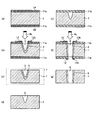
図1は、実施の形態1のレーザ加工方法を示す工程断面図であり、図2は、実施の形態1のレーザ加工方法を示すフローチャートである。図3は、実施の形態1のレーザ加工装置を示す図である。実施の形態1のレーザ加工方法は、レーザによるガラスの貫通穴形成において、貫通穴を形成する途中工程にガラス基板1全体を加熱する工程を含む。第1の工程S101で、貫通しない加工穴2を形成し、第2の工程S102でガラス基板1全体を加熱しガラス基板1への熱応力を除去した状態にし、その上で、第3の工程S103で貫通しない加工穴2から貫通穴8を形成する。実施の形態1で用いられるガラス加工装置は、ガラス基板1を貫通させずに厚み方向の途中まで加工穴2を形成する第1加工部100と、第1加工部100で加工されたガラス基板1のガラス基板1全体を加熱する第2加工部200とを備え、第2加工部200で加工されたガラス基板1に、第1加工部100で加工された加工穴の位置にさらにレーザを照射する。実施の形態1のレーザ加工方法によれば、レーザによるガラスの貫通穴形成において、加工穴よりもテーパの小さい貫通穴8を形成する途中工程にガラス基板1全体を加熱する工程を含んでおり、第2工程でガラス基板1への熱応力を除去した状態にすることが可能である。最終的にガラス基板1に残存する熱応力は最終工程でのレーザ照射回数を含む加工条件に依存する。
FIG. 1 is a process cross-sectional view illustrating the laser processing method according to the first embodiment, and FIG. 2 is a flowchart illustrating the laser processing method according to the first embodiment. FIG. 3 is a diagram illustrating the laser processing apparatus according to the first embodiment. The laser processing method according to the first embodiment includes a step of heating the
図1のようにガラス加熱工程なしで同じ回数だけレーザを照射した場合はガラス基板1に割れが発生するが、ガラス基板1全体を加熱する第2工程を行うことでガラス基板1に割れが発生することなく、レーザを照射する回数を増加することができる。また、一度加工穴を形成した面に対して、さらに反対面からレーザを照射して貫通穴を形成する場合、第1工程で形成した加工穴周囲に残存する熱応力の影響を受けない。よって、割れがなくテーパが少ない、ガラス基板1の熱応力の影響を考慮することなくガラス基板1に貫通穴8を形成する効果がある。
When the laser is irradiated the same number of times without the glass heating step as shown in FIG. 1, the
実施の形態1のレーザ加工方法では、まず、図2に示すように、ステップS101である第1の工程では、図1(a)に示すように、表面1A側からレーザビーム4bを照射すること19で、ガラス基板1を貫通させずに割れあるいはクラックのない加工穴2を形成する。このとき加工穴2の周辺領域には熱応力領域3が形成される。
In the laser processing method of the first embodiment, first, as shown in FIG. 2, in the first step, step S101, the
ステップS102である第2工程では、図1(b)に示すように、ガラス基板1の加工穴周囲を局所的に加熱するのではなく全体加熱部7でガラス基板1全体を加熱する。加熱工程により、図1(c)に示すようにレーザ加工時に発生したガラス基板1への熱応力を除去する。従って熱応力領域3は消失する。
In the second step, which is step S102, as shown in FIG. 1B, the
最後に、ステップS103である第3工程では、第1の工程で形成した加工穴2の位置にさらにレーザビーム4cを表面1A側から照射する。これら3工程を行い、図1(d)に示すように割れあるいはクラックがなくテーパの少ない貫通穴8が形成可能である。このとき、貫通穴8の周辺には熱応力領域6が形成されているが、図1(b)に示した第2工程において全体加熱部7で全体加熱をし、ステップS102までの熱応力は除去されているため、クラックの発生は抑制される。
Finally, in the third step, which is step S103, the
次に、実施の形態1のレーザ加工方法で用いられるレーザ加工装置のレーザ加工部20について説明する。図3は、本発明のガラス加工用レーザ加工装置におけるガラスのレーザ加工装置部分を示す図である。レーザ加工部20は、協調制御でレーザ発振器21から発振されたレーザビーム22を、X方向およびY方向に走査するガルバノスキャナを有するビーム調整光学系23とを有している。ビーム調整光学系23から出力されるレーザビーム22は、ビーム調整光学系23を経てマスク24を介して、X方向導光ミラー25X,Y方向導光ミラー25Yからなる導光ミラー25、集光レンズ26を介してガラス基板1に照射される。ビーム調整光学系23のガルバノスキャナは、加工制御装置27によってX方向導光ミラー25XおよびY方向導光ミラー25Yを回動させることで、レーザ光を、ガラス基板1上の加工エリア内でX方向およびY方向に走査する。ここでレーザ発振器21はCO2レーザを用いている。ガラス基板1をXYZ方向に搬送可能な、搬送部であるステージ台28と、図示しないステージ台駆動部とを有する。
Next, the
レーザ発振器21から、レーザビーム22が生成される。生成されたビーム22をビーム調整光学系23でビーム径の大きさの調整あるいはビーム形状の成形をおこなう。レーザ発振器21は、パルスCO2レーザ発振器である。
A
ビーム調整光学系23は、凹レンズあるいは凸レンズ、凹面鏡あるいは凸面鏡の組み合わせで形成される。楕円ビームなどのビーム成形をおこなう光学系は、シリンドリカルレンズ、プリズム、回折光学素子を使用することができる。
The beam adjusting
マスク24により、レーザビームのプロファイルを成形する。マスク24は銅などの材料で構成された構造体である。マスク24の中心には、マスク24に照射するレーザ径よりも小さな円または楕円などの形状の穴があいている。レーザビーム22がマスク24を通過することで上記形状に成形される。
A profile of the laser beam is formed by the
マスク24を設置せずに、集光レンズ26で集光してビーム照射によりガラス基板1を加工してもよい。
Instead of installing the
マスク24によって成形されたレーザビームを導光ミラー25で導光する。集光レンズ26によりガラス基板1のレーザビーム入射面に集光して、ステージ台28を走査することでガラス基板1に対して微細な加工穴を形成する。
The laser beam formed by the
ガラス基板1への照射レーザビームに対する相対的な走査においては、ステージ台28を固定し、ガルバノミラー、ポリゴンミラーをはじめとする光学系によりレーザビームを走査しても同様の効果を得ることができ、集光レンズ26にFθレンズを用いて照射するのがよい。
In the relative scanning with respect to the laser beam irradiated onto the
ステージ台28は、ボールねじ仕様のステージ、リニアステージなどがあげられる。平面度が高く水平なものがよい。また、レーザに対してガラス基板1の平面度が均一であれば、ガラス基板1の両側を固定する機構を有する者でもよい。例えば、Roll to Rollがあげられる。
Examples of the
ステージ台28にガラス基板1を固定する場合、ガラス基板1の加工部以外の部分に対して固定冶具で数箇所を押し付ける方法、ステージ台28に加工部以外の周囲を真空吸着することで固定する方法などを用いて、水平に固定する。
When the
レーザ加工にはアシストガスを用いてもよい。アシストガスとは、加工時の溶融物の除去、サンプルの冷却の他に、集光レンズ26への溶融物付着防止のために用いる補助ガスのことである。アシストガスの種類には、空気、窒素、アルゴンガスなどがある。アシストガスの流し方は、集光レンズ26とガラス基板1の間に流す方法あるいは、ノズルを用いてレーザ光と同軸上に流す方法がある。
An assist gas may be used for laser processing. The assist gas is an auxiliary gas used for preventing the melt from adhering to the
実施の形態1では、ガラスの微細穴加工用レーザには、ガラスの吸収域である波長をもつレーザがよい。例えば、YAGレーザ、エキシマレーザ、COレーザあるいはCO2レーザなどが適用可能であるが、特にパルスCO2レーザがよい。CO2レーザは固体レーザと比較して、ランニングコストが安く、信頼性の観点において利点がある。 In the first embodiment, a laser having a wavelength that is an absorption region of glass is preferable as the laser for processing fine holes in glass. For example, a YAG laser, an excimer laser, a CO laser, or a CO 2 laser can be applied, and a pulse CO 2 laser is particularly preferable. Compared with a solid-state laser, the CO 2 laser has a lower running cost and is advantageous in terms of reliability.
また、パルスレーザは、連続発振(CW:Continuous Wave)のレーザに比べて、時間的に集中してエネルギーを照射することができる。従って、局所的により深い加工をおこなうことが可能である。特に、微細穴を形成するのに適している。 In addition, a pulsed laser can irradiate energy in a concentrated manner in comparison with a continuous wave (CW) laser. Therefore, deeper processing can be performed locally. It is particularly suitable for forming fine holes.
レーザ発振器21には、ゲインスイッチによってパルスを発生する三軸直交型CO2レーザ発振器を用いるのがよい。
The
三軸直交型レーザ発振器ではガス流路の断面積が大きいため、低ガス圧および低ガス流速でも高出力が得られる。 Since the cross-sectional area of the gas flow path is large in the triaxial orthogonal laser oscillator, a high output can be obtained even at a low gas pressure and a low gas flow rate.
また、ゲインスイッチによるパルスを発生させる方式は、励起放電を断続的に動作させるものである。使用に際しては、単パルス発振後に放電電極間に残った消耗ガスを新しいレーザガスで置換するように充填し、次の励起放電で次のパルスを発生させることで、ピーク出力の高いパルス発振をおこなう。 Further, the method of generating a pulse by a gain switch operates the excitation discharge intermittently. In use, the consumable gas remaining between the discharge electrodes after the single pulse oscillation is filled so as to be replaced with a new laser gas, and the next pulse is generated by the next excitation discharge, thereby generating a pulse oscillation with a high peak output.
ガラスへの微細穴加工用のレーザには、ランニングコストが安く、ゲインスイッチによってパルスを発生させる高ピーク出力な三軸直交型CO2レーザが適している。 As a laser for processing fine holes in glass, a three-axis orthogonal CO 2 laser having a low peak running cost and generating a pulse by a gain switch is suitable.
レーザ照射条件は、レーザの照射ビーム径が直径300μm以下、エネルギー密度が600J/cm2以下であるのが望ましい。パルス幅は100μs以下、さらに50μs以下、さらに望ましくは25μs以下が望ましい。 As for the laser irradiation conditions, it is desirable that the laser irradiation beam diameter is 300 μm or less and the energy density is 600 J / cm 2 or less. The pulse width is preferably 100 μs or less, more preferably 50 μs or less, and further preferably 25 μs or less.
加工対象のガラス基板1には、脆性材料であり、ホウ珪酸ガラス、ソーダガラス、アルカリガラス、無アルカリガラス、合成石英、水晶などの種類のガラスが適用可能である。実施の形態1のガラスのレーザ微細加工において、加工対象のガラスの材質も重要であり、レーザ波長の波長域において光吸収域を有しなければ加工することができない。ガラス基板1には、特に、使用するCO2レーザの波長に対してレーザ光を吸収するガラスが適している。レーザ加工方法を用いて形成されるインターポーザを形成する基板の厚みは、約50μmから500μmである。さらに薄型化が進み、インターポーザを形成する基板は約10μm以上の厚さとなる場合もある。
The
次に、実施の形態1における第2工程のガラス基板1全体を加熱してレーザ加工時に発生したガラス基板1への熱応力を除去する方法について記す。第2工程では図3に示すように、第1工程で加工穴の形成されたガラス基板1を電気炉201内に配し、ガラス基板1全体を加熱する。
Next, a method for heating the
本工程では、ガラス材料の物性値に応じて、レーザ加工時に発生する熱応力が除去可能かつガラス基板が変形する温度未満で、ガラス基板全体を加熱する。加熱手段には、電気炉201の他、電気炉、ホットプレート、赤外線ヒーターが適用可能である。
In this step, the entire glass substrate is heated at a temperature lower than the temperature at which the thermal stress generated during laser processing can be removed and the glass substrate is deformed according to the physical property value of the glass material. As the heating means, in addition to the
本工程で要する時間は、数μ秒、数m秒、数秒のような短い時間ではなく、熱応力除去のために数分、数十分、数時間を要する。そのため、第2工程の加熱は、第1工程のレーザ加工装置から取り出して、別装置での加熱となることが多い。 The time required for this step is not a short time such as several microseconds, several milliseconds, or several seconds, but several minutes, several tens of minutes, and several hours are required for removing thermal stress. For this reason, the heating in the second process is often taken out from the laser processing apparatus in the first process and is heated in a separate apparatus.
なお、レーザ、赤外線ランプをはじめとする熱源を用いてガラス基板1を予熱する、レーザ加工中に加熱する、またはレーザ加工後に余熱するといった方法と、実施の形態1の第2工程の加熱方法とを比較する。前者の工程では、レーザを加工するステージ上で加熱することになるため、ステージ台28上で一定時間停止することになる。しかし、実施の形態1の工程では別装置で加熱するため、ステージ台28上での停止時間分のロスをなくすことができる。従って、生産性を損なうことはない。場合によっては生産性が向上する。
A method of preheating
電気炉201などの加熱装置へのガラス基板1の移動は、ステージ台28から外したガラス基板1自身を移動、またはガラス基板1を固定しているステージ台28と一緒に移動してもよい。
The
最後に、第1工程で形成した加工穴2の位置にさらにレーザビーム4cをガラス基板1の表面1Aまたは反対の面である裏面1Bから照射する第3工程つまり最終工程について記す。
Finally, the third step, that is, the final step, in which the
再び、図3のレーザ加工工程のステージ台28に第1工程で加工したガラス基板1を固定する。または、ガラス基板1の装着されたステージ台28を加工装置に固定する。第1工程と最終工程のレーザ加工装置は別々のレーザ加工装置でもよい。最終工程のレーザ加工装置も図3と同様の仕様を有する。
Again, the
最終工程である第3工程でのレーザ照射径R1は、第1工程のレーザ照射径の直径R0以下とする。また、エネルギー密度が600J/cm2以下であるのが望ましい。 The laser irradiation diameter R 1 in the third process, which is the final process, is set to be equal to or less than the diameter R 0 of the laser irradiation diameter in the first process. The energy density is desirably 600 J / cm 2 or less.
実施の形態1の加工方法において第1工程にてレーザをa回照射して最終工程にてレーザをb回照射した場合と、レーザ照射総回数が同じになるように第2工程の加熱無しでc(c=a+b)回レーザを照射した場合と比較した。実施の形態1の加工方法では、ガラス基板1の割れおよびクラックは発生しなかった。一方、第2工程の加熱無しの場合はクラックが発生した。
In the processing method of
ガラス基板1に割れあるいはクラックを発生させないために、第1工程の加工穴形成時のレーザ照射位置と最終工程である第3工程の貫通穴形成時のレーザ照射位置の距離が、0である、つまり照射位置が同じであることが望ましい。少なくとも第1工程の加工穴形成時のレーザ照射位置と最終工程である第3工程の貫通穴形成時のレーザ照射位置の距離がレーザ照射径の半径の平均値(R0+R1)/2以内である必要がある。加えて、第3工程後に形成された貫通穴において、レーザ照射した面と対抗する面の貫通穴が2つにならないようにする。また図4は、実施の形態1によるレーザ照射条件において、第1工程における加工穴形成時のレーザ照射位置O0と加熱後の第3工程における貫通穴形成時のレーザ照射位置O1の距離xが、第1工程または第3工程のレーザ照射径の半径R0,R1の平均値を超えた距離だけ離れた場合の加工穴を示す図である。
In order not to generate cracks or cracks in the
図5は、実施の形態1によるレーザ照射条件において、加工穴形成時のレーザ照射位置O0と加熱後の貫通穴形成時のレーザ照射位置O1の距離が、レーザ照射径の半径の平均値以内である場合の加工穴を示す図である。 FIG. 5 shows an average value of the radius of the laser irradiation diameter, where the distance between the laser irradiation position O 0 when forming the processed hole and the laser irradiation position O 1 when forming the through hole after heating is the laser irradiation condition according to the first embodiment. It is a figure which shows the processing hole in case it is within.
第1工程の加工穴形成時のレーザ照射位置に対して、図4に示したように最終工程における貫通穴形成時のレーザ照射位置の距離がビーム照射径を超えた値になった場合、ガラス基板1に割れまたはクラック5が発生する。ここでは割れとクラック5とを区別していない。割れまたはクラック5とする。これは、第2工程の加熱により熱応力は除去されているため、第1工程の加工穴の熱応力の影響は無視できる。しかし、第1工程で形成した加工穴と最終工程で形成した加工穴に対して接線を引き、各接線が公差する角度をθとする。θが鋭角の場合、応力集中によりガラス基板1に割れまたはクラック5が発生するためである。
When the distance of the laser irradiation position at the time of forming the through hole in the final process becomes a value exceeding the beam irradiation diameter with respect to the laser irradiation position at the time of forming the processed hole in the first process, as shown in FIG. Cracks or cracks 5 occur in the
第1工程と最終工程のレーザ照射直径が異なる場合、第1工程と最終工程のレーザ照射位置のずれ量である距離xは、両ビームの照射半径の平均値(R0+R1)/2以下である場合、割れまたはクラック5は発生しない。
When the laser irradiation diameters of the first process and the final process are different, the distance x, which is the shift amount between the laser irradiation positions of the first process and the final process, is an average value of the irradiation radii of both beams (R 0 + R 1 ) / 2 In the following cases, no crack or
また、両ビームの照射半径が等しい時は、第1工程の加工穴形成時のレーザ照射位置と最終工程の貫通穴形成時のレーザ照射位置の距離xが、レーザ照射径の半径R0以内であれば、楕円形状の貫通穴が形成可能である。 When the irradiation radii of both beams are equal, the distance x between the laser irradiation position when forming the processed hole in the first step and the laser irradiation position when forming the through hole in the final step is within the radius R 0 of the laser irradiation diameter. If so, an elliptical through hole can be formed.
以下に、本発明の第3工程のレーザ照射位置ずれにおけるクラックの発生の有無に関する例について記す。第1工程のレーザ照射位置を基準とし、(x,y)=(0,0)とする。ここでのX軸方向はガラス面に対して縦方向、Y軸方向は横方向とする。表1は、y=0としX方向のレーザ照射距離を変えた場合の、ガラスの割れまたはクラック発生の有無の結果について示した表である。○は割れあるいはクラック有り、×は割れあるいはクラック無しを示す。 Below, the example regarding the presence or absence of the generation | occurrence | production of the crack in the laser irradiation position shift of the 3rd process of this invention is described. Based on the laser irradiation position in the first step, (x, y) = (0, 0). Here, the X-axis direction is the vertical direction with respect to the glass surface, and the Y-axis direction is the horizontal direction. Table 1 is a table showing the results of whether or not glass breaks or cracks occur when y = 0 and the laser irradiation distance in the X direction is changed. ○ indicates a crack or crack, and × indicates a crack or no crack.

パルスCO2レーザにより、厚さ200μmの無アルカリガラスで形成したガラス基板1に対して、貫通穴を加工した例を示す。レーザの照射条件は、エネルギー密度が500J/cm2である。第1工程および最終工程である第3工程のレーザ照射径は等しく直径2R1=50μmであるものとする。表1より、加工穴形成時のレーザ照射位置と加熱後の貫通穴形成時のレーザ照射位置の距離xが、レーザ照射径の半径25μmを超えたx=30μm以上で割れまたはクラックが発生した。また、x=25μm以下の条件ではガラス基板1は貫通し、貫通穴を形成することができた。
An example in which a through hole is processed on a
また、最終工程のレーザ照射方向は、第1工程と同じガラス面からだけでなく、反対側の面である裏面からも照射してもよい。 Further, the laser irradiation direction in the final process may be irradiated not only from the same glass surface as in the first process but also from the back surface which is the opposite surface.
ただし、反対側からレーザを照射した場合、貫通時に第1工程で形成した加工穴を貫通することになるため、第1工程の加工穴に熱応力が残存する場合、レーザ照射位置に関係なく、ガラス基板1の割れあるいはクラックが発生する。そのため、最終工程で裏面からレーザを照射する場合は、第2工程の加熱工程を必ず実施し、応力緩和領域を形成するのが望ましい。
However, when the laser is irradiated from the opposite side, the processing hole formed in the first step will be penetrated at the time of penetration, so when thermal stress remains in the processing hole in the first step, regardless of the laser irradiation position, The
以上説明したように実施の形態1によれば、レーザによるガラス基板1への貫通穴形成において、貫通穴を形成する途中工程にガラス基板1全体の加熱工程を含むため、第3工程でガラス基板1への熱応力を除去した状態にすることが可能である。最終的にガラス基板1に残存する熱応力は最終工程でのレーザ照射回数を含む加工条件に依存する。第3工程を行うことでガラス基板1に割れを生じることなく、レーザを照射する回数を増加することができる。また、一度加工穴を形成した面に対して、さらに反対面からレーザを照射して貫通穴を形成する場合においても、第1工程で形成した加工穴周囲に残存する熱応力の影響を受けない。よって、割れがなくテーパが少ない、第1工程でのガラス基板1への熱応力を無視した貫通穴を形成することができるという効果がある。
As described above, according to the first embodiment, in the formation of the through hole in the
以上説明してきたように、実施の形態1で用いられたレーザ加工装置は、第1にガラス基板1を貫通させずに厚み方向の途中まで割れあるいはクラックのない加工穴2を形成し、第2に、ガラス基板1を加熱してレーザ加工時に発生したガラス基板1への熱応力を除去し、最後に、第1工程で形成した加工穴の位置に、加工穴2が形成されている面または対向面からレーザを照射することで、レーザ照射回数を増やすことができ、割れあるいはクラックがなくテーパの少ない貫通穴8が形成可能である。
As described above, the laser processing apparatus used in the first embodiment first forms the processed
テーパの少ない貫通穴8を形成するには、レーザの照射回数を増加させる必要がある。しかしながら、照射回数が多いほどガラス基板1への熱応力が増大して割れあるいはクラックが発生し易い。そのため、ガラス基板1の厚さに対して浅い加工穴、すなわち貫通しない深さの加工穴2を形成したのち、ガラス基板1全体を加熱する。ガラス基板1全体を加熱することで、レーザ加工時に発生するガラス基板1への熱応力を除去することができる。ガラス基板1を局所的に加熱、またはガラス加工時に同時に加熱した場合は、ガラス基板1への温度勾配を緩和できるため、熱応力を低減することが可能であるが、熱応力を除去することができない。この状態でさらにレーザを照射した場合、割れが発生する。
In order to form the through
特に、ガラス基板1の両面からレーザを照射して貫通穴を形成する加工方法において、ガラス基板1の片面に熱応力が残存する状態で、その反対の面からレーザを照射すると、ガラス基板1に割れが発生する。
In particular, in a processing method of forming a through hole by irradiating a laser from both surfaces of the
しかし、ガラス基板1全体を加熱した後の加工穴2にレーザを照射して貫通穴8を形成した場合、加熱工程を含まない場合と比較して、最終的にガラス基板1へ発生した熱応力を低減することができ、割れあるいはクラックがなくテーパの少ない貫通穴形成が可能となる。
However, when the through-
また、局所的に加熱する場合は、加熱工程が終わるまでは次の工程に進むことができずにレーザ加工装置の中に滞在する時間が多くなる。しかし、ガラス基板1全体を加熱する別装置での工程を設けることで、ガラス基板1がレーザ加工装置の滞在時間を短縮することができるため、最終的に生産性が向上する。
Further, in the case of locally heating, it is not possible to proceed to the next process until the heating process is completed, and the time spent in the laser processing apparatus increases. However, by providing a process in a separate apparatus that heats the
さらに第1加工部100は、加工穴形成時のレーザ照射位置と、貫通穴形成時のレーザ照射位置との距離が、レーザ照射径の半径の平均値以内であるように制御される。
Further, the
第1工程の加工穴形成時のレーザ照射位置と第3工程の貫通穴形成時のレーザ照射位置の距離が大きく離れた場合、ガラス基板1に割れが発生する。第1工程と第3工程のレーザ照射位置のずれをレーザ照射径の半径の平均値以内にすることで、ガラス基板1の割れの発生を防ぐことができる。
When the distance between the laser irradiation position at the time of forming the processed hole in the first step and the laser irradiation position at the time of forming the through hole in the third step is greatly separated, the
また、第1加工部100は、波長9.0μmから11.0μmのパルスCO2レーザからなるレーザ照射部を備える。なお第3工程の貫通穴形成時に別途第3加工部を用いてもよいし、同一のレーザ装置を共用してもよい。
The
また、第3加工部のレーザ照射径は第1加工部のレーザ照射径以下の大きさが望ましい。第3工程のレーザ照射径が、第1工程のレーザ照射径より大きい場合の加工穴を図13に示す。第1工程で加工穴2を形成した後、加熱し、第3工程で加工穴31を形成するものとする。図13より、第3工程、つまり加熱後に照射するレーザ照射径R1が、第一工程、つまり加熱前に照射したレーザ照射径R0より大きい場合、第3工程で形成される加工穴31は第1工程で形成される加工穴2の穴径よりも大きくなる。図13に示すように最終的な加工穴32の側面に段差が形成されるため、テーパの小さい貫通穴を形成するためには、第3加工部のレーザ照射径は第1加工部のレーザ照射径以下の大きさが望ましい。
Further, it is desirable that the laser irradiation diameter of the third processing portion is smaller than the laser irradiation diameter of the first processing portion. FIG. 13 shows a processing hole when the laser irradiation diameter in the third step is larger than the laser irradiation diameter in the first step. After forming the processed
パルスCO2レーザは、YAGレーザのような固体レーザなど、他のレーザに比べてランニングコストが安価である。ガラスは波長9.0μmから11.0μmに吸収帯をもつことから、パルスCO2レーザを用いることで高ピーク短パルスのレーザ発振により、ガラスに対して一度に高エネルギー密度の加工が可能となる。 The pulse CO 2 laser has a lower running cost than other lasers such as a solid-state laser such as a YAG laser. Since glass has an absorption band from a wavelength of 9.0 μm to 11.0 μm, it is possible to process a glass with a high energy density at a time by using a pulsed CO 2 laser and high-peak short-pulse laser oscillation. .
実施の形態2.
図6(a)から(d)は、実施の形態2のレーザ加工方法を示す工程断面図である。図7は実施の形態2のレーザ加工方法を示すフローチャートである。実施の形態1のレーザ加工方法では、第3工程のレーザ加工が、第1工程のレーザ加工におけるレーザ照射面と同一面側で実施されたのに対し、実施の形態2のレーザ加工方法では、第3工程におけるレーザ加工が、第1工程のレーザ加工におけるレーザ照射面と対向する面に向けてレーザ照射が実施される。
6A to 6D are process cross-sectional views illustrating the laser processing method according to the second embodiment. FIG. 7 is a flowchart showing the laser processing method of the second embodiment. In the laser processing method of the first embodiment, the laser processing of the third step is performed on the same side as the laser irradiation surface in the laser processing of the first step, whereas in the laser processing method of the second embodiment, In the laser processing in the third step, laser irradiation is performed toward the surface facing the laser irradiation surface in the laser processing in the first step.
実施の形態1では、第1工程、第3工程共に同一面側からレーザ照射して貫通穴を形成する加工工程であったのに対して、実施の形態2では、第3工程でのレーザ照射面が、第1工程での裏面1Bである点で異なる。図6(d)に示すように、実施の形態1による片側からレーザ照射して貫通穴8を形成する加工工程に対して、実施の形態2の方法では、第3工程でのレーザ照射面が、対向面すなわち裏面1Bである点で異なる。つまり、加工穴2の位置にさらに裏面1Bからレーザビーム4dの照射を行うステップS103Sが異なる。他の工程は実施の形態1と同様であるため、ここでは説明を省略する。
In the first embodiment, the first step and the third step are both processing steps in which the laser irradiation is performed from the same surface side to form a through hole, whereas in the second embodiment, the laser irradiation in the third step is performed. The surface is different in that it is the
また、第3工程でガラス基板1に貫通穴加工をする場合は、ステージ台28側にある貫通穴形成領域のガラス面はステージ台28と接しないようにするのが望ましい。これは、貫通穴加工時にガラス基板1の溶融物が穴の内側から外側へ排出されるが、上記ステージ台28側のガラス面がステージ台28と接する場合は排出し難い状態となり、熱が排出できずに熱影響層あるいはクラックが発生する場合もある。
Further, when the through hole processing is performed on the
そのため、ステージ台28の貫通穴形成領域に相当する領域を含む貫通溝29Sを設けるなどの方法で貫通穴形成領域でガラス基板1の裏面がステージ台28に接触しない状態にして加工をおこなう必要がある。
Therefore, it is necessary to perform processing in such a manner that the back surface of the
実施の形態3.
図8(a)から(f)は、実施の形態3のレーザ加工方法を示す工程断面図である。図9は実施の形態3のレーザ加工方法を示すフローチャートである。実施の形態3のレーザ加工方法は、実施の形態1のレーザ加工方法における、第3工程のレーザ加工の後すなわち、貫通穴形成後にさらにガラス基板1全体を加熱するステップS104を実施する。
8A to 8F are process cross-sectional views illustrating the laser processing method according to the third embodiment. FIG. 9 is a flowchart showing the laser processing method of the third embodiment. The laser processing method of the third embodiment performs step S104 of further heating the
図8(a)から(f)では、実施の形態1による片側からレーザ照射して貫通穴8を形成する加工工程に対して、貫通穴形成後した後、さらにガラス基板1全体を加熱するステップS104を追加した点で異なる。他の工程は実施の形態1と同様であるため、ここでは説明を省略する。図8(e)のように最終工程のレーザ加工後に第4工程を実施し、ガラス基板1全体を加熱してガラス基板1の熱応力領域6を除去し、図8(f)に示すガラス基板1を形成する。また、ガラス基板1の両面から加工する場合においても、第3工程の後に加工されたガラス基板1全体を加熱する第4工程であるステップS104をさらに実施してもよい。
8 (a) to 8 (f), the step of heating the
本実施の形態においても、第3工程でガラス基板1に貫通穴加工をする場合は、ステージ側にあるガラス面はステージ台28と接しないようにするのが望ましい。これは、貫通穴加工時にガラスの溶融物が穴の内側から外側へ排出されるが、上記ステージ台28側のガラス面がステージ台28と接する場合は排出し難い状態となり、熱が排出できずに熱影響層あるいはクラックが発生する場合もある。
Also in the present embodiment, when the through hole processing is performed on the
そのため、図8(d)に示すようにステージ台28に溝29を設けるなどの方法で裏面が接触しない状態にして加工をおこなう必要がある。溝29を設けることで、効率よくガラスの溶融物が穴の内側から外側へ排出される。
Therefore, as shown in FIG. 8 (d), it is necessary to perform processing in such a manner that the back surface is not in contact by a method such as providing a
上記方法によれば、より確実に熱応力を除去することができ、使用時における割れあるいはクラックの発生を回避することができ、信頼性の向上をはかることが可能となる。 According to the above method, it is possible to more reliably remove the thermal stress, to avoid the occurrence of cracks or cracks during use, and to improve the reliability.
なお、実施の形態3においても第3工程は、第1工程と同一の装置または同構成の装置で実施する。また、第4工程は第2加工部と同一の装置または同構成の別装置で実施する。 In the third embodiment as well, the third step is performed by the same apparatus or the same configuration as the first step. The fourth step is performed by the same device as the second processing unit or another device having the same configuration.
実施の形態4.
図10(a)から(g)は、実施の形態4のレーザ加工方法を示す工程断面図である。図11は実施の形態4のレーザ加工方法を示すフローチャートである。実施の形態4のレーザ加工方法は、加工時に発生するガラスの溶融物あるいは飛散物がガラス基板1に付着する場合がある。これらを防ぐために実施の形態4の方法では、ガラス基板1表面に保護材11a,11bを貼着する。
Embodiment 4 FIG.
FIGS. 10A to 10G are process cross-sectional views illustrating the laser processing method of the fourth embodiment. FIG. 11 is a flowchart showing the laser processing method according to the fourth embodiment. In the laser processing method of the fourth embodiment, a glass melt or scattered matter generated during processing may adhere to the
図10(a)に示すように、実施の形態4によるレーザ加工工程において、ガラス基板1の表面および裏面に保護材11aを貼着し、保護材11aによってガラス基板1表面および裏面を保護するものであり、保護材の着脱工程を含むレーザ加工工程を示す図である。
As shown in FIG. 10A, in the laser processing step according to the fourth embodiment, a
本発明におけるレーザ加工工程において、ガラス基板1の表面および裏面に保護材11a,11bを貼着した、保護材付ガラスを用いた場合について述べる。まず、図11に示すステップS100aで、10(a)に示すように第1工程のレーザ加工前に保護材11aをガラス基板1の表面および裏面に貼着する。ステップS101で、レーザ照射による加工穴の形成を行う。10(b)に示すようにレーザ加工後にガラス基板1から保護材11aを剥離するステップS100bを実施し、ガラスの溶融物12あるいは飛散物12hを保護材11aごと除去する。第1工程で使用する保護材11aは、ガラス基板1の両面に形成する。保護材11aをガラス基板1の両面に形成することで、より、確実な保護が可能であるが、ガラス基板1の片面つまりレーザ照射側の面だけに形成してもよい。また、第3工程で貫通穴8を形成する場合はガラス基板1の両面に保護材11bを形成するのが望ましい。
In the laser processing step of the present invention, a case where glass with a protective material in which
次に10(c)に示すように、ステップS102である第2工程を実施し、ガラス基板1全体を加熱し、ガラス基板1の熱応力領域3を除去する。以上の工程で図10(d)に示すように、熱応力領域3のない貫通穴2を有するガラス基板1を得る。
Next, as shown in 10 (c), the second step which is Step S <b> 102 is performed, the
第2工程後、図11に示すステップS200aで、10(e)に示すように再びガラス基板1の両面に保護材11bを形成する。
After the second step, the
そして図11に示すステップS103で、10(f)に示すように加工穴2の位置にレーザ照射を行い、貫通穴8を形成するステップS103を実施する。
Then, in step S103 shown in FIG. 11, laser irradiation is performed on the position of the
第3工程でレーザ加工後に保護材11bを剥離し、図11に示すステップ200bで、10(g)に示すように貫通加工時に発生するガラスの溶融物12あるいは飛散物12hを保護材11bごと除去する。ここでは、貫通穴8を形成するため、ガラス基板1の両面からガラス基板1の飛散物12hあるいは溶融物12が発生するため、ガラス基板1の両面に保護材11bを形成する。このとき、貫通穴8の周辺には熱応力領域6が形成されているが、図10(b)に示した第2工程において全体加熱部7で全体加熱をし、ステップS102までの熱応力は除去されているため、クラックの発生は抑制される。さらに全体加熱を行い熱応力領域6を除去するようにしてもよい。
After the laser processing in the third step, the
最終工程である第3工程で用いる保護材11bは、第1工程で用いた保護材11aと同じでもよいし、異なっていてもよい。
The
保護材について以下に述べる。保護材の選び方は、被加工物の材料とレーサ加工条件によって選択する。保護材は十分な耐熱性が備える必要がある。ここで述べる十分な耐熱性とは、保護材をレーザ加工したときに、基材の変形がほとんどなく、保護材がレーザの熱に耐え切れずに焼き焦げないことや、保護材が焼失してガラス面が露出しないことを示す。保護材の耐熱性が十分に確保されていない場合、保護材によるガラスの溶融物あるいは飛散物の除去が困難であるだけでなく、ガラスへの熱影響層やクラックが発生するためである。 The protective material is described below. The method of selecting the protective material is selected according to the material of the workpiece and the racer processing conditions. The protective material must have sufficient heat resistance. The sufficient heat resistance described here means that when the protective material is laser processed, there is almost no deformation of the base material, the protective material cannot withstand the heat of the laser and cannot be burned, or the protective material is burned out. Indicates that the glass surface is not exposed. This is because when the heat resistance of the protective material is not sufficiently ensured, it is difficult to remove the molten or scattered material of the glass by the protective material, and a heat-affected layer and cracks are generated on the glass.
保護材は基材と接着剤からなり、基材は2層以上の積層体で構成してもよい。保護材の基材の厚さは、ガラス基板1の厚さ以下とするのがよい。レーザ加工時に保護材はガラス基板1より大きくてもよい。ただし、保護材付きガラスはステージ台の大きさ以下にする。ステージ台の周縁で折れ曲がり、破損の原因になる可能性があるためである。
A protective material consists of a base material and an adhesive agent, and a base material may comprise a laminated body of two or more layers. The thickness of the base material of the protective material is preferably equal to or less than the thickness of the
基材の材質には、例えばポリエチレンテレフタレート、ポリエチレンナフタレート、ポリイミドなどの高分子フィルムなどがあげられる。接着剤は、ゴム系、シリコーン系、アクリル系とあるが、仮接着または剥離可能な材質を用いる。ガラスに直接接着する接着剤の接着範囲は、レーザ加工部よりも大きい必要がある。接着剤の厚さは、使用する材質の粘着力によるが20μm以下が望ましい。接着剤の粘着力はガラス基板1と保護材11a,11bとの密着性があればよい。粘着力は、0.05N/20mmから1.0N/20mmが望ましい。保護材を構成する基材および接着剤の厚さは、レーザ加工性を良くするために均一であるほうがよい。
Examples of the material of the substrate include polymer films such as polyethylene terephthalate, polyethylene naphthalate, and polyimide. There are rubber, silicone, and acrylic adhesives, but temporary adhesive or peelable materials are used. The adhesion range of the adhesive that directly adheres to the glass needs to be larger than that of the laser processed portion. The thickness of the adhesive is preferably 20 μm or less depending on the adhesive strength of the material used. The adhesive strength of the adhesive only needs to be close to the
保護材を、ガラス基板1とともに加工できるように、ガラスの吸収域である波長をもつレーザで加工するのがよい。例えば、YAGレーザ、エキシマレーザ、COレーザ、CO2レーザなどがある。特にCO2レーザの波長に対してレーザ光を吸収する材質が適している。使用するCO2レーザの波長は9.0μmから11.0μmであることが好ましい。
The protective material is preferably processed with a laser having a wavelength that is an absorption region of the glass so that the protective material can be processed together with the
レーザ加工後のガラスからの保護材の剥離方法として、手で保護材を剥離する方法、保護材の端をロールなどの治具を用いて剥離する方法などがある。また、水溶性の接着剤を用いた場合は、水洗洗浄にて剥離する。 As a method of peeling the protective material from the glass after laser processing, there are a method of peeling the protective material by hand, a method of peeling the end of the protective material using a jig such as a roll, and the like. When a water-soluble adhesive is used, it is peeled off by washing with water.
以上、本発明のレーザ加工工程に保護材の着脱工程を加えることで、ガラスに対してクラック、溶融物あるいは飛散物のない加工形状が均一な加工が可能である。 As described above, by adding the protective material attaching / detaching step to the laser processing step of the present invention, it is possible to uniformly process the glass without cracks, melts or scattered matters.
前述したように、第1工程における保護材と、第3工程における保護材とは、異なる仕様を有するものであってもよい。第1工程の加工穴形成前にガラス基板1に形成する保護材と、第3工程の貫通穴加工前にガラス基板1に形成する第2保護材の仕様が異なってもよい。保護材を用いる第1工程と第3工程において、ガラス基板1に割れやクラックがなく、溶融物あるいは飛散物の付着がない高品位のガラスを提供できるレーザ加工が可能な保護材であれば、保護材を構成する基材あるいは接着剤の種類あるいは厚さが異なってもよい。
As described above, the protective material in the first step and the protective material in the third step may have different specifications. The specifications of the protective material formed on the
実施の形態5.
本発明のレーザ加工の第1工程では、ガラス基板に対してレーザを照射する場合、ガラスの厚み方向の途中位置までではなく、貫通穴を形成してもよい。
In the first step of laser processing of the present invention, when irradiating a laser on a glass substrate, a through hole may be formed instead of up to a midway position in the thickness direction of the glass.
図12は、本発明の実施の形態5によるレーザ加工工程において、第1工程で貫通穴を形成する、片側からレーザ照射して貫通穴を形成する加工工程を示す図である。 FIG. 12 is a diagram showing a processing step of forming a through hole in the first step and forming a through hole by laser irradiation from one side in the laser processing step according to the fifth embodiment of the present invention.
実施の形態5のガラスに微細穴を形成するためのレーザ加工方法について、以下に記す。まず、第1の工程でのガラス基板1を割れのない貫通穴8tを形成する加工穴の形成方法について記す。第1の工程では、ガラス基板1の第1または第2主面である表面および裏面1A,1Bのうちのいずれかの一面に対してレーザビーム4bを照射する。貫通穴はテーパが大きく、側面の傾斜が緩やかな形状になっている。
A laser processing method for forming fine holes in the glass of
第1工程で形成される、図12(a)に示すような貫通穴8tは、ガラス表面および内部あるいは加工穴の周囲に割れあるいはクラックが無いことが品質として必要である。
The through-
第1工程で貫通穴を形成することで、レーザ照射側と反対側の面側に、レーザ加工による解けたガラスが排出されやすくなる。 By forming the through hole in the first step, the glass melted by the laser processing is easily discharged on the side opposite to the laser irradiation side.
また、第1工程でガラスに保護材を使用する場合は、ガラスの両面に保護材を形成するのが望ましい。 Moreover, when using a protective material for glass at the 1st process, it is desirable to form a protective material on both surfaces of glass.
図12(a)から図12(d)に工程断面図を示すように、第1工程で、貫通穴8tを形成し、後は図1(b)から図1(d)に示したのと同様の処理を行うようにしてもよい。図12(d)で形成される貫通穴8は、第1工程で形成された貫通穴8tよりもテーパが小さく急峻な断面形状となっている。
As shown in FIG. 12 (a) to FIG. 12 (d), the through
以上説明したように本実施の形態5によれば、レーザによるガラスの貫通穴形成において、第1工程でテーパの大きい、傾斜の緩やかな貫通穴を形成した後、側面の傾斜が第1工程で形成された貫通穴よりも急峻なテーパをもつ貫通穴を形成するため、レーザ照射側と反対側の面側に、レーザ加工による解けたガラスが排出されやすくなる。 As described above, according to the fifth embodiment, in forming a glass through-hole by laser, after forming a through-hole having a large taper and a gentle slope in the first step, the side surface is inclined in the first step. Since the through hole having a steeper taper than the formed through hole is formed, glass melted by laser processing is easily discharged to the surface side opposite to the laser irradiation side.
また、途中工程にガラス全体の加熱工程を含むため、第2工程でガラスへの熱応力を除去した状態にすることが可能である。第2工程を行うことでガラスに割れあるいはクラックを生じることなくレーザを照射する回数を増加することができる。従って、最終工程では、第1工程で形成した加工穴の周囲に残存する熱応力の影響を受けずに、割れがなくテーパが少ない、第1工程でのガラスへの熱応力を無視したガラス貫通穴を形成する効果がある。 Moreover, since the heating process of the whole glass is included in the middle process, it is possible to make it the state which removed the thermal stress to glass at the 2nd process. By performing the second step, the number of times of laser irradiation can be increased without causing cracks or cracks in the glass. Therefore, in the final process, the glass penetration is neglected by the thermal stress on the glass in the first process, without being affected by the thermal stress remaining around the processed hole formed in the first process, without cracking and with a small taper. There is an effect of forming a hole.
以上の実施の形態に示した構成は、本発明の内容の一例を示すものであり、別の公知の技術と組み合わせることも可能であるし、本発明の要旨を逸脱しない範囲で、構成の一部を省略、変更することも可能である。 The configuration described in the above embodiment shows an example of the contents of the present invention, and can be combined with another known technique, and can be combined with other configurations without departing from the gist of the present invention. It is also possible to omit or change the part.
1 ガラス基板、2 加工穴、3 熱応力領域、4b,4c,4d レーザビーム、5 クラック、6 熱応力領域、7 全体加熱部、8 貫通穴、10 ガラスインターポーザ、11a 保護材、11b 保護材、12 溶融物、12h 飛散物、13 第1電極、14 第2電極、15 貫通電極、16 CPU、17 メモリ、20 レーザ加工部、21 レーザ発振器、22 レーザビーム、23 ビーム調整光学系、24 マスク、25 導光ミラー、26 集光レンズ、27 加工制御装置、28 ステージ台、29 溝、M メモリ装置、31 加工穴、32 最終的な加工穴、100 第1加工部、200 第2加工部。
DESCRIPTION OF
Claims (16)
前記第1加工部で加工された前記ガラス基板全体を加熱する第2加工部とを備え、
前記第2加工部で加工された前記ガラス基板に、前記第1加工部で加工された前記加工穴の位置にさらにレーザを照射し、貫通穴を形成することを特徴とするレーザ加工装置。 A first processed part that forms a processed hole by irradiating a laser up to a middle position in the thickness direction with respect to the glass substrate;
A second processing unit for heating the entire glass substrate processed by the first processing unit,
A laser processing apparatus, wherein the glass substrate processed by the second processing unit is further irradiated with a laser at a position of the processing hole processed by the first processing unit to form a through hole.
前記第1加工部の加工穴形成時のレーザ照射位置と、前記貫通穴形成時のレーザ照射位置との距離は、前記レーザ制御部によって、前記第1加工部および前記貫通穴形成時のレーザ照射径の平均半径以内に制御されることを特徴とする請求項1に記載のレーザ加工装置。 A laser control unit for controlling the first processing unit;
The distance between the laser irradiation position at the time of forming the processed hole of the first processed portion and the laser irradiation position at the time of forming the through hole is determined by the laser control unit by the laser irradiation at the time of forming the first processed portion and the through hole. The laser processing apparatus according to claim 1, wherein the laser processing apparatus is controlled within an average radius.
前記第3加工部のレーザ照射径は、前記第1加工部のレーザ照射径以下であることを特徴とする請求項1に記載のレーザ加工装置。 The glass substrate processed by the second processing unit further includes a third processing unit that irradiates a laser at a position of the processing hole processed by the first processing unit to form a through hole,
The laser processing apparatus according to claim 1, wherein a laser irradiation diameter of the third processing unit is equal to or less than a laser irradiation diameter of the first processing unit.
レーザ照射前の前記ガラス基板の表面または裏面に保護材を貼着する保護材貼着部と、
レーザ照射後の前記ガラス基板の表面または裏面の前記保護材を剥離する保護材剥離部とを備えたことを特徴とする請求項1または2に記載のレーザ加工装置。 The first processing unit includes:
A protective material attaching portion for attaching a protective material to the front surface or the back surface of the glass substrate before laser irradiation;
The laser processing apparatus according to claim 1, further comprising: a protective material peeling portion that peels off the protective material on the front surface or the back surface of the glass substrate after laser irradiation.
前記第1工程で加工された前記ガラス基板全体を加熱する第2工程と、
前記第2工程で加工された前記ガラス基板に、前記第1工程で加工された前記加工穴の位置にさらにレーザを照射し、貫通穴を形成する第3工程とを備えたことを特徴とするレーザ加工方法。 A first step of irradiating a laser to a glass substrate up to a middle position in the thickness direction to form a processed hole;
A second step of heating the entire glass substrate processed in the first step;
The glass substrate processed in the second step further includes a third step of irradiating the position of the processed hole processed in the first step with a laser to form a through hole. Laser processing method.
レーザ照射後、前記ガラス基板の表面または裏面の前記保護材を剥離する保護材剥離工程とを備えたことを特徴とする請求項7から10のいずれか1項に記載のレーザ加工方法。 Prior to the laser irradiation in the first step, a protective material attaching step of attaching a protective material to the front surface or the back surface of the glass,
The laser processing method according to claim 7, further comprising: a protective material peeling step for peeling off the protective material on the front surface or the back surface of the glass substrate after the laser irradiation.
レーザ照射後、前記ガラス基板の表面または裏面の前記第2保護材を剥離する第2保護材剥離工程とを備えたことを特徴とする請求項11に記載のレーザ加工方法。 Prior to laser irradiation in the third step, a second protective material adhering step of adhering a second protective material to the front or back surface of the glass substrate;
The laser processing method according to claim 11, further comprising: a second protective material peeling step of peeling the second protective material on the front surface or the back surface of the glass substrate after laser irradiation.
Priority Applications (1)
| Application Number | Priority Date | Filing Date | Title |
|---|---|---|---|
| JP2016074610A JP6590749B2 (en) | 2016-04-01 | 2016-04-01 | Laser processing apparatus and laser processing method |
Applications Claiming Priority (1)
| Application Number | Priority Date | Filing Date | Title |
|---|---|---|---|
| JP2016074610A JP6590749B2 (en) | 2016-04-01 | 2016-04-01 | Laser processing apparatus and laser processing method |
Publications (3)
| Publication Number | Publication Date |
|---|---|
| JP2017186185A JP2017186185A (en) | 2017-10-12 |
| JP2017186185A5 JP2017186185A5 (en) | 2018-12-06 |
| JP6590749B2 true JP6590749B2 (en) | 2019-10-16 |
Family
ID=60046096
Family Applications (1)
| Application Number | Title | Priority Date | Filing Date |
|---|---|---|---|
| JP2016074610A Active JP6590749B2 (en) | 2016-04-01 | 2016-04-01 | Laser processing apparatus and laser processing method |
Country Status (1)
| Country | Link |
|---|---|
| JP (1) | JP6590749B2 (en) |
Families Citing this family (3)
| Publication number | Priority date | Publication date | Assignee | Title |
|---|---|---|---|---|
| KR102030521B1 (en) * | 2017-11-30 | 2019-10-10 | (주)에스엠텍 | Glass surface machining device for solar module using laser |
| CN113828943B (en) * | 2021-09-18 | 2023-10-03 | 湖北优尼科光电技术股份有限公司 | Processing method of glass substrate |
| CN114933407B (en) * | 2022-05-18 | 2023-07-14 | 常州亚玛顿股份有限公司 | Preparation method of through hole glass substrate for mini LED backlight structure and backlight structure |
Family Cites Families (8)
| Publication number | Priority date | Publication date | Assignee | Title |
|---|---|---|---|---|
| US4441008A (en) * | 1981-09-14 | 1984-04-03 | Ford Motor Company | Method of drilling ultrafine channels through glass |
| JPH0679486A (en) * | 1992-08-25 | 1994-03-22 | Rohm Co Ltd | Working method for ink jet head |
| JP2001354439A (en) * | 2000-06-12 | 2001-12-25 | Matsushita Electric Ind Co Ltd | Method for working glass substrate and method for making high-frequency circuit |
| US8584354B2 (en) * | 2010-08-26 | 2013-11-19 | Corning Incorporated | Method for making glass interposer panels |
| JP2014214036A (en) * | 2013-04-24 | 2014-11-17 | 旭硝子株式会社 | Method for forming through-hole through glass substrate by using laser |
| CN105705468B (en) * | 2013-11-14 | 2018-11-16 | 三菱电机株式会社 | Laser processing and laser processing device |
| JP2015213949A (en) * | 2014-05-09 | 2015-12-03 | ビアメカニクス株式会社 | Laser processing method |
| JP2015229167A (en) * | 2014-06-04 | 2015-12-21 | ビアメカニクス株式会社 | Laser processing method |
-
2016
- 2016-04-01 JP JP2016074610A patent/JP6590749B2/en active Active
Also Published As
| Publication number | Publication date |
|---|---|
| JP2017186185A (en) | 2017-10-12 |
Similar Documents
| Publication | Publication Date | Title |
|---|---|---|
| JP7090594B2 (en) | Equipment and methods for laser machining | |
| KR101795327B1 (en) | Laser processing method and laser processing apparatus | |
| JP2018525309A (en) | How to cut a thin glass layer | |
| TWI637922B (en) | Chamfering method of glass substrate and laser processing device | |
| US20150059411A1 (en) | Method of separating a glass sheet from a carrier | |
| TW201601900A (en) | Laser cut composite glass article and method of cutting | |
| US11904410B2 (en) | Laser surface preparation of coated substrate | |
| JP6590749B2 (en) | Laser processing apparatus and laser processing method | |
| JP2016193814A (en) | Cutting method of brittle substrate | |
| JP4831003B2 (en) | Repairing surface scratches on the surface of glass substrates by laser irradiation | |
| CN112839908B (en) | Laser processing of brittle material separation and release | |
| US20220288723A1 (en) | Method and apparatus for forming holes in brittle materials assisted by stress reduction through heating | |
| JP2008062547A (en) | Method and device for splitting rigid brittle plate by laser irradiation | |
| EP3596019B1 (en) | Controlled separation of laser processed brittle material | |
| Abramov et al. | Laser forming of holes in brittle materials assisted by stress reduction through heating | |
| JP2014177369A (en) | Manufacturing method of tempered glass member | |
| EP4159357A1 (en) | Method of and apparatus for cutting a substrate or preparing a substrate for cleaving | |
| TWI394630B (en) | Laser processing method and laser processing device | |
| JP6889922B2 (en) | Residual stress reduction method for glass substrate and residual stress reduction device for glass substrate | |
| JP2015123461A (en) | Laser processing method and manufacturing method for substrate where through hole is formed | |
| TW202348576A (en) | Glass plate and production method therefor |
Legal Events
| Date | Code | Title | Description |
|---|---|---|---|
| A521 | Request for written amendment filed |
Free format text: JAPANESE INTERMEDIATE CODE: A523 Effective date: 20181022 |
|
| A621 | Written request for application examination |
Free format text: JAPANESE INTERMEDIATE CODE: A621 Effective date: 20181022 |
|
| TRDD | Decision of grant or rejection written | ||
| A977 | Report on retrieval |
Free format text: JAPANESE INTERMEDIATE CODE: A971007 Effective date: 20190815 |
|
| A01 | Written decision to grant a patent or to grant a registration (utility model) |
Free format text: JAPANESE INTERMEDIATE CODE: A01 Effective date: 20190820 |
|
| A61 | First payment of annual fees (during grant procedure) |
Free format text: JAPANESE INTERMEDIATE CODE: A61 Effective date: 20190917 |
|
| R150 | Certificate of patent or registration of utility model |
Ref document number: 6590749 Country of ref document: JP Free format text: JAPANESE INTERMEDIATE CODE: R150 |
|
| R250 | Receipt of annual fees |
Free format text: JAPANESE INTERMEDIATE CODE: R250 |
|
| R250 | Receipt of annual fees |
Free format text: JAPANESE INTERMEDIATE CODE: R250 |