JP6590277B2 - Biological information acquisition device - Google Patents
Biological information acquisition device Download PDFInfo
- Publication number
- JP6590277B2 JP6590277B2 JP2015156793A JP2015156793A JP6590277B2 JP 6590277 B2 JP6590277 B2 JP 6590277B2 JP 2015156793 A JP2015156793 A JP 2015156793A JP 2015156793 A JP2015156793 A JP 2015156793A JP 6590277 B2 JP6590277 B2 JP 6590277B2
- Authority
- JP
- Japan
- Prior art keywords
- measurement
- biological information
- information acquisition
- unit
- brain
- Prior art date
- Legal status (The legal status is an assumption and is not a legal conclusion. Google has not performed a legal analysis and makes no representation as to the accuracy of the status listed.)
- Active
Links
- 238000005259 measurement Methods 0.000 claims description 181
- 210000004556 brain Anatomy 0.000 claims description 79
- 210000003625 skull Anatomy 0.000 claims description 70
- 239000000758 substrate Substances 0.000 claims description 26
- 238000003825 pressing Methods 0.000 claims description 21
- 239000007788 liquid Substances 0.000 claims description 20
- 238000001514 detection method Methods 0.000 claims description 7
- 238000010171 animal model Methods 0.000 claims description 4
- 238000000605 extraction Methods 0.000 claims description 4
- 230000003925 brain function Effects 0.000 description 32
- 238000000034 method Methods 0.000 description 9
- 230000003287 optical effect Effects 0.000 description 8
- 210000000056 organ Anatomy 0.000 description 7
- 230000000638 stimulation Effects 0.000 description 7
- 238000005452 bending Methods 0.000 description 5
- 238000012986 modification Methods 0.000 description 5
- 230000004048 modification Effects 0.000 description 5
- 239000011347 resin Substances 0.000 description 5
- 229920005989 resin Polymers 0.000 description 5
- 238000004891 communication Methods 0.000 description 4
- 238000010586 diagram Methods 0.000 description 4
- 230000000694 effects Effects 0.000 description 4
- 230000006870 function Effects 0.000 description 4
- 239000002131 composite material Substances 0.000 description 3
- 238000003780 insertion Methods 0.000 description 3
- 230000037431 insertion Effects 0.000 description 3
- 230000008859 change Effects 0.000 description 2
- 238000005516 engineering process Methods 0.000 description 2
- 210000003128 head Anatomy 0.000 description 2
- 238000001727 in vivo Methods 0.000 description 2
- 238000007917 intracranial administration Methods 0.000 description 2
- 210000004185 liver Anatomy 0.000 description 2
- 239000000463 material Substances 0.000 description 2
- 230000002265 prevention Effects 0.000 description 2
- 210000004761 scalp Anatomy 0.000 description 2
- 238000000926 separation method Methods 0.000 description 2
- WQZGKKKJIJFFOK-GASJEMHNSA-N Glucose Natural products OC[C@H]1OC(O)[C@H](O)[C@@H](O)[C@@H]1O WQZGKKKJIJFFOK-GASJEMHNSA-N 0.000 description 1
- 241001465754 Metazoa Species 0.000 description 1
- VYPSYNLAJGMNEJ-UHFFFAOYSA-N Silicium dioxide Chemical compound O=[Si]=O VYPSYNLAJGMNEJ-UHFFFAOYSA-N 0.000 description 1
- 230000005856 abnormality Effects 0.000 description 1
- 230000036982 action potential Effects 0.000 description 1
- 238000007792 addition Methods 0.000 description 1
- 239000008280 blood Substances 0.000 description 1
- 210000004369 blood Anatomy 0.000 description 1
- 230000007177 brain activity Effects 0.000 description 1
- 238000012937 correction Methods 0.000 description 1
- 230000008878 coupling Effects 0.000 description 1
- 238000010168 coupling process Methods 0.000 description 1
- 238000005859 coupling reaction Methods 0.000 description 1
- 238000011161 development Methods 0.000 description 1
- 206010012601 diabetes mellitus Diseases 0.000 description 1
- 201000010099 disease Diseases 0.000 description 1
- 208000037265 diseases, disorders, signs and symptoms Diseases 0.000 description 1
- 238000002566 electrocorticography Methods 0.000 description 1
- 206010015037 epilepsy Diseases 0.000 description 1
- 239000012530 fluid Substances 0.000 description 1
- 239000008103 glucose Substances 0.000 description 1
- 238000003384 imaging method Methods 0.000 description 1
- 230000007257 malfunction Effects 0.000 description 1
- 239000011159 matrix material Substances 0.000 description 1
- 210000000214 mouth Anatomy 0.000 description 1
- 230000007383 nerve stimulation Effects 0.000 description 1
- 230000000149 penetrating effect Effects 0.000 description 1
- 230000002093 peripheral effect Effects 0.000 description 1
- 230000008569 process Effects 0.000 description 1
- 238000012545 processing Methods 0.000 description 1
- 238000012827 research and development Methods 0.000 description 1
- 230000008054 signal transmission Effects 0.000 description 1
- 230000036555 skin type Effects 0.000 description 1
Images


Landscapes
- Measurement And Recording Of Electrical Phenomena And Electrical Characteristics Of The Living Body (AREA)
- Measuring And Recording Apparatus For Diagnosis (AREA)
Description
本発明は、各種の実験動物や人間(ヒト)等の生体における様々な生体関連情報を取得するための生体情報取得装置に関し、さらに詳しくは、少なくとも一部が、生体の外表面や生体内の臓器等の特定の部位の表面に接触するように取り付けられ、その生体外表面や生体内部位の表面を通して生体関連情報を取得する生体情報取得装置に関する。 The present invention relates to a biological information acquisition apparatus for acquiring various biological information related to various biological animals such as various experimental animals and humans (humans), and more particularly, at least a part of the living body external surface or in vivo The present invention relates to a biological information acquisition apparatus that is attached so as to be in contact with the surface of a specific part such as an organ and acquires biological related information through the surface of the living body or the surface of the biological part.
近年の脳科学や医療用計測技術の進展は目覚ましく、脳機能関連情報を収集するための各種のセンシングデバイスや新しい脳機能イメージング技術が実現されている。脳機能関連情報計測用のデバイスは、大別して侵襲型と非侵襲型とに区分される。侵襲型とは電極などを直接的に脳に接触させるために、被検体の頭皮や頭蓋骨の切開など、何らかの外科的手術をも伴うものである。これに対し、非侵襲型とは被検体の頭部の外側から間接的に(つまり頭皮や頭蓋骨などを通して)脳にアクセスし、何らかの脳機能関連情報を取得するものである。 Recent advances in brain science and medical measurement technologies have been remarkable, and various sensing devices and new brain function imaging technologies have been realized to collect information related to brain functions. Devices for measuring brain function-related information are roughly classified into invasive types and non-invasive types. The invasive type involves some kind of surgical operation such as incision of the scalp or skull of a subject in order to bring an electrode or the like into direct contact with the brain. On the other hand, the non-invasive type accesses the brain indirectly from the outside of the subject's head (that is, through the scalp, skull, etc.) and acquires some brain function related information.
非侵襲型装置は生体に対する損傷を与えない又は抑えられるという点で優れているものの、取得可能な情報の種類や精度等にはかなりの制約がある。そのため、高い精度、高い分解能で脳機能関連情報を得るため、或いは、通常の活動を行っている状態の被検体の脳機能関連情報を或る程度長期間に亘り取得するためには、少なくとも装置の一部を被検体の脳に接触させる侵襲型脳計測が必要である。 Although a non-invasive device is excellent in that it does not damage or suppress a living body, there are considerable restrictions on the type and accuracy of information that can be acquired. Therefore, in order to obtain brain function related information with high accuracy and high resolution, or to acquire brain function related information of a subject in a normal activity state for a long period of time, at least the device An invasive brain measurement in which a part of the brain is brought into contact with the subject's brain is necessary.
侵襲型脳機能計測デバイスとしては、大別して、脳表型計測を行うものと脳刺入型計測を行うものとがある。脳刺入型のデバイスは文字通り、針状電極を脳内に刺入して脳内の比較的深い部分の電気信号を取得可能としたものであるのに対し、脳表型デバイスは脳の表面に密着するように電極等を配置して電気信号を取得するものである。こうした脳表型デバイスとしてはECoG電極と呼ばれるものが知られており、我が国において、てんかんなどの臨床治療用として認可されているユニークメディカル社の頭蓋内電極がある(非特許文献1参照)。脳表型デバイスは脳刺入型と比べると空間分解能は劣るものの、脳に与えるダメージが少なく性能の経時劣化も小さくて済む。また、広範囲の計測にも向いている。こうしたことから、被検体の自由な活動を阻害せずに、比較的長期間に亘り安定した脳機能関連情報を取得するには、脳表型計測が有利であるといえる。 Invasive brain function measuring devices are roughly classified into those that perform brain surface type measurement and those that perform brain insertion type measurement. The brain-embedded device is literally a needle-like electrode inserted into the brain to obtain a relatively deep electrical signal in the brain, whereas the brain surface-type device is the surface of the brain. An electric signal is obtained by arranging electrodes or the like so as to be in close contact with each other. Such a brain surface device is known as an ECoG electrode. In Japan, there is an intracranial electrode of Unique Medical, which is approved for clinical treatment of epilepsy and the like (see Non-Patent Document 1). Although the brain surface-type device is inferior to the brain insertion type in spatial resolution, it does not damage the brain and degrades performance over time. It is also suitable for a wide range of measurements. For this reason, it can be said that brain surface type measurement is advantageous in order to obtain stable brain function-related information for a relatively long period of time without hindering the free activity of the subject.
上述したように被検体の自由な活動を阻害することなく比較的長期間計測を継続するには、被検体の体内と外部との接続は無線方式があることが望ましい。こうした観点から、本願発明者らは特許文献1において、脳表面に接触する電極、脳に対し光学的な刺激を与えるLED、該LEDからの照射光に対し脳から得られた散乱光や反射光などを検出する光センサなどが搭載された体内ユニットと、体外に設置される体外ユニットとの間で信号の送受を無線で行う脳機能計測装置を提案している。この装置では、体内ユニットは被検体の頭蓋骨(又は人工頭蓋骨)の外側に装着され、棒状の電極が頭蓋骨や人工頭蓋骨に穿設された穴に挿通されてその先端部が脳表面に接触するように構成されている。
As described above, in order to continue measurement for a relatively long period of time without hindering the free activity of the subject, it is desirable that the connection between the inside and outside of the subject be a wireless system. From this point of view, the inventors of the present invention disclosed in
一方、本願発明者らは、分散型アーキテクチャによるフレキシブル脳計測・脳刺激デバイスの研究・開発を長年に亘り続けている。これは、CMOS集積回路による小型の神経刺激用及び計測用のチップをフレキシブル基板上に複数搭載したものであり、該デバイスを被検体の脳表面に接触するように配置する(非特許文献2参照)。そして、複数のチップを協調して動作させることで、脳の広い範囲の活動電位計測を行えるようにしている。 On the other hand, the present inventors have continued research and development of a flexible brain measurement / stimulation device based on a distributed architecture for many years. This is a device in which a plurality of small nerve stimulation and measurement chips based on a CMOS integrated circuit are mounted on a flexible substrate, and the device is arranged so as to be in contact with the brain surface of the subject (see Non-Patent Document 2). ). A plurality of chips are operated in a coordinated manner so that action potentials can be measured over a wide range of the brain.
こうした脳機能計測装置において計測の空間分解能を上げるには、電極サイズを小さくし、それを高い密度で2次元的に配置する必要がある。また、脳の活動や機能についての有用な情報を得るには、脳のできるだけ広い範囲をカバーする計測を行うことが望ましい。こうした計測を行うために従来の装置では次のような問題がある。 In order to increase the spatial resolution of measurement in such a brain function measuring apparatus, it is necessary to reduce the electrode size and arrange it two-dimensionally with high density. In addition, in order to obtain useful information about brain activity and function, it is desirable to perform measurement covering the widest possible range of the brain. In order to perform such measurement, the conventional apparatus has the following problems.
即ち、一般に、脳の表面は複雑な曲面形状であり、ほぼ平面であるとみなせる程度の狭い範囲であれば、複数の電極を脳表面に密着させることは容易である。しかしながら、脳全体やその大部分に及ぶような広い範囲において、複数の電極を脳表面に密着させることは難しい。また、上述したように頭蓋骨や人工頭蓋骨に穿設された穴に電極が挿通される構成であれば、頭蓋骨や人工頭蓋骨に対し電極の位置は正確に決まるが、回路基板上に電極を搭載し、該回路基板を脳表面と頭蓋骨や人工頭蓋骨との間の間隙に配置する構成では、回路基板の位置がずれて電極での計測位置が変化するおそれがある。また、脳表面と頭蓋骨や人工頭蓋骨との間の距離が経時的に変化すると、脳表面への電極の密着性が低下するおそれがある。さらにまた、脳表面と頭蓋骨や人工頭蓋骨との間に配置されるデバイスに搭載可能な回路の規模は、頭蓋骨や人工頭蓋骨の外側に配置されるユニットに比べてかなり限定される。一方で、電極やLED、光センサなどの数を増やすと処理すべき信号の量も増大するため、そうした多量の信号を頭蓋骨や人工頭蓋骨の内側に配置されるICチップ等で処理するのは困難であるという問題もある。 That is, generally, the surface of the brain has a complicated curved surface shape, and it is easy to make a plurality of electrodes adhere to the brain surface within a narrow range that can be regarded as being almost flat. However, it is difficult to bring a plurality of electrodes into close contact with the brain surface over a wide range that covers the entire brain or most of it. In addition, as described above, if the electrode is inserted into the hole drilled in the skull or artificial skull, the position of the electrode is accurately determined with respect to the skull or artificial skull, but the electrode is mounted on the circuit board. In the configuration in which the circuit board is disposed in the gap between the brain surface and the skull or the artificial skull, the position of the circuit board may be shifted and the measurement position on the electrode may be changed. In addition, when the distance between the brain surface and the skull or artificial skull changes with time, the adhesion of the electrode to the brain surface may be reduced. Furthermore, the scale of a circuit that can be mounted on a device arranged between the brain surface and the skull or artificial skull is considerably limited as compared to a unit arranged outside the skull or artificial skull. On the other hand, if the number of electrodes, LEDs, photosensors, etc. is increased, the amount of signals to be processed also increases, so that it is difficult to process such a large amount of signals with an IC chip or the like placed inside the skull or artificial skull. There is also the problem of being.
ここまでは被検体の脳刺激や脳計測を行う装置について述べてきたが、それは特に脳については高精度、高分解能の計測が要求されるためであって、生体内の臓器などの他の部位においても同様の手法による刺激や計測が有用である場合があることは言うまでもない。こうした場合にも、上述した問題が生じることになる。また、生体内ではなく、皮膚等の生体の外表面に接触するように設けた電極、LED、光センサ等を用いて生体刺激や生体計測を行う場合でも同様である。即ち、上記従来の脳機能計測装置における課題は、脳機能計測のみならず、同様の手法で以て生体情報を取得する際に生じる課題でもある。 Up to this point, we have described a device that performs brain stimulation and brain measurement of a subject. This is because, particularly for the brain, measurement with high accuracy and high resolution is required. Needless to say, there are cases in which stimulation and measurement using the same method may be useful. Even in such a case, the above-described problem occurs. The same applies to biostimulation and measurement using electrodes, LEDs, photosensors, and the like provided so as to be in contact with the outer surface of the living body, such as skin, instead of in vivo. That is, the problem in the conventional brain function measuring apparatus is not only a brain function measurement but also a problem that occurs when biometric information is acquired by a similar method.
本発明はこうした課題に鑑みて成されたものであり、その主たる目的は、計測対象である又は電気的な若しくは光学的な刺激を与える対象である脳や臓器などの生体内の特定の部位の表面や生体外表面の曲面形状が複雑であっても、その表面に良好に密着し、広い範囲に対し高い密度で刺激を加えたり計測を行ったりすることができる生体情報取得装置を提供することにある。 The present invention has been made in view of these problems, and the main purpose of the present invention is to measure a specific part in a living body such as a brain or an organ which is a measurement target or a target to which electrical or optical stimulation is applied. To provide a biometric information acquisition apparatus that can adhere well to a surface and has a high density over a wide range even if the curved shape of the surface or the surface of the living body is complex, and can perform measurements at a high density It is in.
上記課題を解決するために成された本発明は、各種の実験動物やヒトを含む生体である被検体の脳の表面から電気的及び/又は光学的に生体情報を収集する生体情報取得装置であって、
a)それぞれが被検体の脳の表面に接触するように設けられ、電気的に生体情報を取得する電極部、及び/又は、光学的に生体情報を取得する受光部、を含む略平板状である複数の計測サブユニットと、
b)2次元的に配置されてなる前記複数の計測サブユニットがその位置関係を維持し得るように一つの計測サブユニットとその周囲に配置されている他の計測サブユニットとを繋ぐようにその間にそれぞれ設けられ、一つの計測サブユニットと隣接する他の計測サブユニットとを電気的に接続する信号線を含むフレキシブル基板による複数の連結部と、
c)前記複数の計測サブユニットのうちの一つに接続され、その複数の全ての計測サブユニットの電極部及び/又は受光部で得られた生体情報を反映した信号を外側へ取り出すための取り出し配線部と、
を有する計測ユニットを少なくとも一つ備え、前記被検体の頭蓋骨の一部に代えて該頭蓋骨に装着される人工頭蓋骨の内側に前記計測ユニットを保持する保持部を設け、該保持部により前記計測ユニットを人工頭蓋骨と脳との間の間隙に保持し、前記複数の計測サブユニットのうちの任意の一つの計測サブユニットとその周囲に配置されている他の複数の計測サブユニットとの間にそれぞれ設けられている複数の前記連結部の信号線は同じ電気信号を送受するように構成されていることを特徴としている。
The present invention made to solve the above problems is a biological information acquisition apparatus that electrically and / or optically collects biological information from the surface of the brain of a subject that is a living body including various experimental animals and humans. There,
a) Each is provided so as to be in contact with the surface of the subject's brain , and has a substantially flat plate shape including an electrode part for electrically acquiring biological information and / or a light receiving part for optically acquiring biological information. A number of measurement subunits,
b) Between one measurement subunit and other measurement subunits arranged around it so that the plurality of measurement subunits arranged two-dimensionally can maintain their positional relationship. A plurality of connecting portions by a flexible substrate including a signal line electrically connected to one measurement subunit and another measurement subunit adjacent thereto,
c) Extraction for extracting signals reflecting biological information obtained by the electrodes and / or the light receiving units of all of the plurality of measurement subunits connected to one of the plurality of measurement subunits. A wiring section;
A holding unit for holding the measurement unit is provided inside an artificial skull to be attached to the skull instead of a part of the skull of the subject, and the holding unit holds the measurement unit. Is held in the gap between the artificial skull and the brain, and between any one of the plurality of measurement subunits and a plurality of other measurement subunits arranged around it. The signal lines of the plurality of connecting portions provided are configured to transmit and receive the same electrical signal.
複数の連結部の信号線が同じ電気信号を送受するように構成するには、具体的には例えば、全ての連結部に含まれる信号線を共通のバスラインとし、各計測サブユニットに搭載されている電気回路がそれぞれ共通のバスラインに接続される構成、つまりはバスライン方式による接続形態を採ればよい。 In order to configure the signal lines of a plurality of connecting parts to transmit and receive the same electrical signal, specifically, for example, the signal lines included in all the connecting parts are used as a common bus line and are mounted on each measurement subunit. A configuration in which the electric circuits are connected to a common bus line, that is, a connection form by a bus line method may be employed.
本発明に係る生体情報取得装置では例えば、一つの計測サブユニットは外形が上面視六角形状のリジッド基板上に各種部品を搭載した構成であり、ハニカム状に配置された多数の計測サブユニットが、それぞれ最大6個の連結部によって周りを囲む最大6個の他の計測サブユニットとそれぞれ接続される構成とすることができる。連結部は可撓性を有するフレキシブル基板から成るから、該連結部を適宜に屈曲させることで、連なった計測サブユニットが曲面状になるようにすることができる。しかしながら、或る一つの計測サブユニットの3次元的な動きは連結部を介して接続されている周りの複数の計測サブユニットによって或る程度拘束されるため、連結部がいかに可撓性を有していても、多数の計測サブユニットによって形成される曲面の形状は限られる。 In the biological information acquisition apparatus according to the present invention, for example, one measurement subunit is configured such that various parts are mounted on a rigid board having an outer shape of a hexagonal shape when viewed from above, and a large number of measurement subunits arranged in a honeycomb shape are provided. Each can be configured to be connected to each of up to six other measurement subunits surrounding each other by a maximum of six connecting portions. Since the connecting portion is made of a flexible flexible substrate, the connected measuring subunits can be curved by appropriately bending the connecting portion. However, since the three-dimensional movement of a single measurement subunit is constrained to some extent by a plurality of measurement subunits connected through the connection portion, how flexible the connection portion is. Even so, the shape of the curved surface formed by many measurement subunits is limited.
これに対し本発明に係る生体情報取得装置では、一つの計測サブユニットに接続されている複数の連結部の信号線には同じ信号が送受されるため、その複数の連結部のうちのいずれか一つのみを残して他を切断しても、残された一つの連結部の信号線を通し、さらに隣接する一以上の計測サブユニットを介して、取り出し配線部が接続されている計測サブユニットに信号を送ることができる。即ち、各計測サブユニットにおいて一つ以上の連結部を介して他の計測サブユニットとの接続が確保されていさえすれば、その計測ユニットに含まれる全ての計測サブユニットの電極部や受光部で得られた信号を、取り出し配線部を通して、例えば生体表面や生体内の特定部位表面でない位置に設けられた別の回路ユニットへ送ることができる。 On the other hand, in the biological information acquisition device according to the present invention, the same signal is transmitted and received to the signal lines of the plurality of connecting portions connected to one measurement subunit, and thus any one of the plurality of connecting portions. Even if only one is cut off and the other is cut, the measurement sub-unit is connected to the lead-out wiring section through one or more adjacent measurement sub-units through the signal line of the remaining connection section Can be signaled. That is, as long as the connection to other measurement subunits is ensured via one or more coupling parts in each measurement subunit, the electrodes and light receiving parts of all measurement subunits included in the measurement unit The obtained signal can be sent, for example, to another circuit unit provided at a position other than the surface of the living body or the surface of the specific part in the living body through the extraction wiring portion.
こうして、一つの計測サブユニットと隣接する計測サブユニットを繋ぐ連結部のうち不要なものを切断することによって、各計測サブユニットの動きの制約が小さくなるので動きの自由度が増し、計測ユニットに含まれる各計測サブユニットを、複雑な曲面形状である生体表面や特定部位表面に良好に接触させることができるようになる。 In this way, by cutting unnecessary ones of the connecting parts that connect one measurement subunit and the adjacent measurement subunit, the restriction on movement of each measurement subunit is reduced, so the degree of freedom of movement is increased and the measurement unit is Each of the measurement subunits included can be brought into good contact with the surface of a living body or the surface of a specific part that has a complicated curved surface shape.
連結部に用いられるフレキシブル基板は通常、可撓性はあるものの伸縮性は乏しい。そこで、屈曲の際の自由度を高めるために、上記連結部は、外部から力を加えない状態で略U字状に屈曲した状態を保つように立体形状加工されたフレキシブル基板からなるものとするとよい。これにより、連結部を屈曲させる際の遊びが大きくなるので、計測サブユニットや連結部に無理な力が加わることなく、各計測サブユニットを生体表面や特定部位表面にフィットさせることができる。 The flexible substrate used for the connecting portion is usually flexible but has poor stretchability. Therefore, in order to increase the degree of freedom in bending, the connecting portion is made of a flexible substrate that is three-dimensionally processed so as to maintain a substantially U-shaped bent state without applying a force from the outside. Good. Thereby, since the play at the time of bending a connection part becomes large, each measurement subunit can be made to fit a living body surface or the surface of a specific part, without applying excessive force to a measurement subunit or a connection part.
本発明に係る生体情報取得装置において、人工頭蓋骨の内側の保持部は各計測サブユニットを保持するようにしてもよいが、上述したように連結部がU字状に立体形状加工されたフレキシブル基板から成る場合には、そのU字状の突部が人工頭蓋骨の内面に向くように連結部を設け、そのU字状の突部を保持部で保持する構成とするとよい。
このような構成を採ることで、計測ユニットを人工頭蓋骨の内側に固定することができ、脳表面の計測箇所を一旦決めると、その計測箇所が経時的にずれてしまうことを防止することができる。
In the biological information acquisition apparatus according to the present invention, the holding part inside the artificial skull may hold each measurement subunit, but as described above, the flexible board in which the connecting part is processed into a U-shape. In this case, the connecting portion may be provided so that the U-shaped projection faces the inner surface of the artificial skull, and the U-shaped projection is held by the holding portion.
By adopting such a configuration, the measurement unit can be fixed inside the artificial skull, and once the measurement location on the brain surface is determined, the measurement location can be prevented from shifting over time. .
また本発明に係る生体情報取得装置では、上記人工頭蓋骨の所定位置に形成された開口に挿通され、その内側に向いた面が前記計測サブユニットに当接する押圧部を複数備え、人工頭蓋骨の外側から押圧部を挿入する長さを調整することで該押圧部による前記計測サブユニットの押し付け状態を調整し、該計測サブユニットに含まれる電極部と脳表面との密着性を確保する構成とするとよい。 Further, in the biological information acquiring apparatus according to the present invention, the artificial skull is provided with a plurality of pressing portions that are inserted into openings formed at predetermined positions of the artificial skull and whose inner surface faces the measurement subunit. By adjusting the length of insertion of the pressing part from the adjusting part, the pressing state of the measurement subunit by the pressing part is adjusted, and the adhesion between the electrode part included in the measuring subunit and the brain surface is ensured. Good.
一例としては、人工頭蓋骨にはネジ溝を形成した開口を穿設し、押圧部はそのネジ溝に螺合するネジ山が周囲に形成されたボルト状部材であるものとすることができる。この構成によれば、押圧部を開口に螺入してゆくに従い計測サブユニットは内側に押し込まれ、例えば電極部と脳表面との密着性が向上する。 As an example, an opening in which a screw groove is formed is formed in the artificial skull, and the pressing portion may be a bolt-shaped member around which a screw thread that is screwed into the screw groove is formed. According to this configuration, the measurement subunit is pushed inward as the pressing portion is screwed into the opening, and, for example, the adhesion between the electrode portion and the brain surface is improved.
また本発明に係る生体情報取得装置では、人工頭蓋骨の内部に液体が流通する又は貯留される通液路を形成するとともに、該人工頭蓋骨と計測サブユニットとの間に、前記通液路中の液体によって押圧される柔軟性を有する押圧部を設け、前記通液路に流す又は溜める液体の液圧を調整することで該押圧部による前記計測サブユニットの押し付け状態を調整する構成としてもよい。
In the biological information acquisition apparatus according to the present invention are both If you form a liquid passing path in the interior of the artificial skull liquids are to or stored distribution, between the artificial skull and the measurement subunit, the liquid passing path A configuration may be provided in which a pressing portion having flexibility to be pressed by the liquid therein is provided and the pressing state of the measurement subunit by the pressing portion is adjusted by adjusting the liquid pressure of the liquid that flows or accumulates in the liquid passage. Good.
人工頭蓋骨の位置が頭蓋骨に対して固定されていたとしても、人工頭蓋骨の内面と脳表面との間の距離は経時的に変化する可能性がある。これに対し上記構成では、通液路中に供給する液体の量を被検体の体外から調整できるようにしておくことで、該被検体の頭部を切開することなく、電極部と脳表面との密着性を調整することができる。それによって、長期間に亘り、良好な脳機能計測を継続することが可能である。 Even if the position of the artificial skull is fixed relative to the skull, the distance between the inner surface of the artificial skull and the brain surface may change over time. On the other hand, in the above-described configuration, the amount of liquid supplied into the liquid passage can be adjusted from outside the body of the subject, so that the electrode portion and the brain surface can be connected without incising the head of the subject. Can be adjusted. Thereby, it is possible to continue good brain function measurement over a long period of time.
また本発明に係る生体情報取得装置では、上記人工頭蓋骨は頭蓋骨に固定されるホルダに対して装着され、該人工頭蓋骨の外側に重ねた制御ユニット用ハウジングを前記ホルダに対し装着し、該制御ユニット用ハウジングの内部に、少なくとも前記計測ユニットに搭載された電気回路を制御する回路及び被検体の体外に設置された体外ユニットとの間での無線での信号送受を行う回路を含む制御ユニットを配設する構成とするとよい。 Further, in the biological information acquiring apparatus according to the present invention, the artificial skull is attached to a holder fixed to the skull, a control unit housing overlaid on the outside of the artificial skull is attached to the holder, and the control unit A control unit including at least a circuit for controlling an electric circuit mounted on the measurement unit and a circuit for performing wireless signal transmission / reception between the external unit installed outside the body of the subject is disposed inside the housing for measurement. It is good to have a configuration to be installed.
人工頭蓋骨と脳表面との間の間隙にスペース的な制約があるため、この間隙に設置される計測サブユニットに搭載可能な素子や回路には限界がある。これに対し上記構成では、複雑な信号処理を行うような回路は計測サブユニットではなく制御ユニットに設けることができるので、計測サブユニットに搭載する素子や回路を最小限に抑えることができる。また、制御ユニットに搭載される回路は或る程度規模が大きくなるが、人工頭蓋骨の外側に配置することでスペースの制約が緩和される。また、ホルダに装着された制御ユニット用ハウジングの内部に制御ユニットを設けることで、計測ユニットや制御ユニットが一体化され、扱いも容易になる。 Since there is a space limitation on the gap between the artificial skull and the brain surface, there is a limit to the elements and circuits that can be mounted on the measurement subunit installed in this gap. On the other hand, in the above configuration, a circuit that performs complex signal processing can be provided in the control unit instead of the measurement subunit, so that the elements and circuits mounted on the measurement subunit can be minimized. In addition, the circuit mounted on the control unit is somewhat larger in scale, but space constraints are eased by placing the circuit outside the artificial skull. Further, by providing the control unit inside the control unit housing mounted on the holder, the measurement unit and the control unit are integrated, and the handling becomes easy.
また上述したように本発明に係る生体情報取得装置では、一つの計測サブユニットと他の計測サブユニットとを繋ぐ複数の連結部の一部を意図的に切断しても、計測サブユニットで得られた信号が最終的に取り出し配線部を通して外部へと送出されるようになっているが、意図的な切断ではなく意図せずに連結部が切断されたときに、その切断を検知可能な切断検知部を組み込んでおくとよい。
該切断検知部としては、切断された連結部の位置を特定可能である構成と、いずれかの連結部が切断されたことのみを検知可能である構成とが考えられる。
In addition, as described above, in the biological information acquisition device according to the present invention, even if a part of a plurality of connecting portions that connect one measurement subunit and another measurement subunit is intentionally cut, the measurement subunit can obtain it. The signal is finally sent to the outside through the extraction wiring part, but when the connection part is cut unintentionally rather than intentionally, the disconnection can be detected. It is advisable to incorporate a detector.
As the disconnection detection unit, there can be considered a configuration capable of specifying the position of the cut connecting portion and a configuration capable of detecting only one of the connecting portions being cut.
この構成によれば、計測ユニットが被検体の生体内の特定部位に装着された状態で一部の連結部が切れたときに、その状態を迅速に把握して例えばその特定部位に何らかの異常が生じた等の事態を推測することができる。
According to this configuration, when some of the connecting parts are disconnected while the measurement unit is attached to a specific part of the subject in the living body, the state is quickly grasped, and for example, there is some abnormality in the specific part. It is possible to guess what happened .
本発明に係る生体情報取得装置によれば、例えば個体差があり複雑な曲面形状を有する脳などの生体内部の特定部位の表面の広い範囲に対し、電気的な計測を行う電極部や光学的な計測を行う受光部を良好に且つ高い密度で密着させることができる。それによって、被検体の脳等の特定部位の表面の広い範囲に亘る高い分解能の計測を行うことができ、その被検体に関する有用な生体情報を収集することができる。
According to the biological information acquiring apparatus according to the present invention, for example, an electrode unit or an optical unit that performs electrical measurement on a wide range of the surface of a specific part inside a living body such as a brain having individual differences and a complicated curved surface shape. It is possible to make the light-receiving part that performs accurate measurement adhere well with high density. Thereby, measurement with high resolution over a wide range of the surface of a specific part such as the brain of the subject can be performed, and useful biological information regarding the subject can be collected .
まず、本発明に係る生体情報取得装置の一実施例である脳機能測装置について、添付図面を参照して詳細に説明する。
図1は本実施例の脳機能計測装置の要部のブロック構成図、図2は本実施例の脳機能計測装置における一つの計測サブユニットの概略内部配線図、図3は本実施例の脳機能計測装置における計測ユニットの平面図(a)及び該計測ユニットに含まれる計測サブユニットの拡大平面図(b)である。また図5は、一つの計測サブユニット及び隣接する計測サブユニット間を繋ぐ連結部の概略断面図である。
First, a brain function measuring apparatus which is an embodiment of a biological information acquiring apparatus according to the present invention will be described in detail with reference to the accompanying drawings.
FIG. 1 is a block diagram of the main part of the brain function measuring apparatus of this embodiment, FIG. 2 is a schematic internal wiring diagram of one measurement subunit in the brain function measuring apparatus of this embodiment, and FIG. 3 is the brain of this embodiment. It is the top view (a) of the measurement unit in a function measuring device, and the enlarged plan view (b) of the measurement subunit contained in this measurement unit. FIG. 5 is a schematic cross-sectional view of a connecting portion that connects one measurement subunit and adjacent measurement subunits.
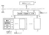
本実施例の脳機能計測装置は、被検体の体内に設置される計測ユニット2及び制御ユニット3と、該被検体の体外に設置される体外ユニット5と、を含む。
計測ユニット2は多数の計測サブユニット1を含み、各計測サブユニット1は、電極11、基準電極12、LED13、及びフォトダイオード(PD)14を含む。一つの制御ユニット3はそれぞれケーブル線4を介して複数の計測ユニット2と接続されている。制御ユニット3は、制御部31、電源部32、インターフェイス(I/F)部33などを備える。制御ユニット3と体外ユニット5との間は、電波などによる無線通信で相互に接続されている。これは特許文献1に記載の装置と全く同様である。
The brain function measuring apparatus according to the present embodiment includes a
The
本実施例の脳機能計測装置において、計測サブユニット1の電極11及び基準電極12は被検体の脳の表面に接触するように設けられるものである。制御ユニット3とケーブル線4を介して接続される一つの計測ユニット2は、図3(a)に示すように、多数の計測サブユニット1が連結部17で接続された構成を有する。図3(b)に示すように、一つの計測サブユニット1は上面視で正六角形状のリジッド基板10を有し、このリジッド基板10は連結部17であるフレキシブル基板と一体化されてリジッドフレキシブル複合基板となっている。図3の例では、一つの計測サブユニット1のリジッド基板10上に、12個の電極11、1個の基準電極12、6個のLED13、1個のPD14が搭載されている。基準電極12及びPD14はリジッド基板10の略中央に設けられ、電極11及びLED13はそれぞれリジッド基板10全体に適宜に分散して配置されている。一つの計測サブユニット1の大きさは、対向する2辺の間の距離が5.2mm、1辺の長さが3mmである。また、連結部17の長さ(つまりは連結部17で接続されている二つの計測サブユニット1の間の離間距離)は1.3mmである。
In the brain function measuring apparatus of the present embodiment, the
図5(a)に示すように、一つの計測サブユニット1において、電極11及び基準電極12は複合基板の裏面に接触部が露出するように該基板に貫設され、LED13やPD14は該基板を貫通するように形成された窓10aを通して光を発したり光を受けたりするように、基板の表面に取り付けられている。窓10aは単なる穴でもよいが、石英ガラス等、長期間に亘り安定的に高い透明性が得られる材料を埋め込んだものでもよい。
As shown in FIG. 5A, in one
隣接する計測サブユニット1同士が接続される連結部17は可撓性を有するフレキシブル基板であるため、計測ユニット2を脳表面100に取り付ける際には、連結部17を自由に湾曲させることができる。さらに、本実施例の構成では、連結部17として、通常のフレキシブル基板ではなく、図5に示すように、外部から力を加えない状態で略U字状に屈曲した状態を保つように立体形状加工されたフレキシブル基板を用いている。一般的にフレキシブル基板は可撓性は高いものの伸縮性には乏しいため、隣接する計測サブユニット1の離間距離を調整するのは難しい。それに対し、本実施例の構成では、連結部17に略U字状屈曲部17aが設けられていることで伸縮が可能であるため、図5(b)に示すように、曲面である脳表面100に電極11、12の先端面が良好に接触するように隣接する計測サブユニット1の離間距離を適当に長くしつつ連結部17を湾曲させることができる。
Since the connecting
図3(a)に示すように、一つの計測ユニット2において計測サブユニット1同士は、周囲に配置されたものを除き、6個の連結部17によってその周囲の6個の他の計測サブユニット1と接続されている。6個の連結部17は全く同じ機能を有する。即ち、図2に示すように、一つの計測ユニット2において信号のやり取りはバスライン方式となっており、一つの計測サブユニット1において電極11、基準電極12、LED13、PD14は、PD14が一体化されたCMOS−ICに内蔵されているインターフェイス部15を介してバス配線16に接続されている。また、一つの計測サブユニット1に一端が接続されている最大6個の連結部17それぞれのケーブル線もバス配線16に接続されている。したがって、計測サブユニット1間の相互接続は多重化(最大で六重化)されており、或る一つの計測サブユニット1が6個の連結部17を介して周囲の6個の計測サブユニット1と接続されている場合には、そのうちの5個の連結部17が切断されても通信が可能である。
As shown in FIG. 3 (a), in one
計測ユニット2は上記構成を有するため、任意の一つの計測サブユニット1は、制御ユニット3との間の通信を担うケーブル線4が接続されている計測サブユニット(図3(a)では計測サブユニット1A)との間で任意の一つの経路で接続されていればよく、その経路以外の連結部17を切断することができる。図4はこのように連結部17を切断した構成の例であり、切断箇所に×印を記載してある。この例では、外周側に位置する計測サブユニット1は一つの連結部17でのみその内側の計測サブユニット1と接続されている。上述したように連結部17は可撓性及び略U字状屈曲部17aによる伸縮性を有するものの、隣接する他の計測サブユニット1との接続箇所が多いと曲面に沿わせて曲げるのが難しい場合がある。それに対し、この計測ユニット2では、適宜の位置の連結部17を切り離しても構わないので、3次元的な可撓性が向上し、曲面の形状に合わせた曲げの自由度を高めることができる。それによって、各計測サブユニット1における電極11、基準電極12の脳表面100への密着性を高めることができる。
Since the
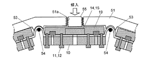
図6は本実施例の脳機能計測装置において生体内に設置されるユニットの構造及び装着状態を示す概略断面図、図7は計測ユニットの固定方法を説明するための概略断面図である。
上述した計測ユニット2は、被検体の頭蓋骨の一部を切除した開口に装着される人工頭蓋骨の内側に固定される。即ち、一部が切除された頭蓋骨の開口部に固定用リング50が取り付けられ、その固定用リング50の内側に人工頭蓋骨51が固定されている。人工頭蓋骨51の内面(脳表に対向する面)の適宜の位置には断面略U字状の溝である嵌合部53が形成されており、連結部17の略U字状屈曲部17aを嵌合部53に挿入し、該略U字状屈曲部17aを間に挟んで脱落防止部材54を嵌合部53に嵌め込むことで、連結部17を人工頭蓋骨51に固定する。なお、必ずしも切除されずに残っている全ての連結部17を嵌合部53に固定する必要はない。このようにして、一つの計測ユニット2に含まれる各計測サブユニット1は人工頭蓋骨51の内側の適切な位置におおむね固定される。
なお、図5では記載を省略していたが、人工頭蓋骨51に計測ユニット2を固定する際には、各計測サブユニット1にあって複合基板のおもて面は、PD14やインターフェイス部15を含むCMOS−ICやLED13などの回路全体を保護するように樹脂モールド19で固められる。
FIG. 6 is a schematic cross-sectional view showing the structure and mounting state of a unit installed in a living body in the brain function measuring apparatus of the present embodiment, and FIG. 7 is a schematic cross-sectional view for explaining a fixing method of the measurement unit.
The above-described
Although not shown in FIG. 5, when fixing the
一方、固定用リング50に取り付けられた人工頭蓋骨51の外面には、制御ユニット3が内部に配置された、樹脂等からなる制御ユニットハウジング52が取り付けられており、制御ユニット3と計測ユニット2とは人工頭蓋骨51を貫通するケーブル線4によって相互に接続されている。このようにして、制御ユニット3と計測ユニット2とを人工頭蓋骨51と一体化することができ、扱いも容易になる。
On the other hand, on the outer surface of the
本実施例の脳機能計測装置は以下のような動作により、被検体の脳の活動等を反映した脳機能関連情報を収集することができる。即ち、体外ユニット5は被検体の体内に設置された制御ユニット3との間で無線で信号のやり取りを行い、制御ユニット3に含まれる制御部31はケーブル線4を介して1又は複数の計測ユニット2に含まれる各計測サブユニット1の電極11から信号を収集する。図3(a)、図4等に示すように、電極11は脳表面100の広い範囲をカバーするように適度に分散して配置されているため、脳表面1100から満遍なく脳機能を反映した信号を集めることができる。基準電極12は計測サブユニット1内の複数の電極11で得られた信号の基準電位を得るために用いることができるほか、電気的刺激を与えるために微弱な電流を脳表面100に流すために利用することもできる。
The brain function measuring apparatus according to the present embodiment can collect brain function related information reflecting the activity of the brain of the subject by the following operation. That is, the extracorporeal unit 5 wirelessly exchanges signals with the
上述したような電気的な計測とは別に又は電気的な計測と並行して、各計測サブユニット1のLED13を所定時間駆動し、LED13から発せられた所定波長の光を脳表面100に照射する。PD14は、照射光に対し脳表面100で反射した光や脳内部に侵入し拡散して出射して来た光を受光し、光電変換した検出信号を出力する。各計測サブユニット1で得られた検出信号はバス配線16を通して計測サブユニット1Aに集められ、最終的にケーブル線4を通して制御ユニット3へ送られる。こうして、電気的及び/又は光学的に収集された信号はインターフェイス部33から無線で体外ユニット5へと送られ、体外ユニット5に備えられたメモリなどに保存される。
Separately or in parallel with the electrical measurement as described above, the
上記実施例の脳機能計測装置において、計測ユニット2は人工頭蓋骨51の内側に固定されていたが、この場合、計測サブユニット1の厚さと、人工頭蓋骨51内面と脳表面100との間の隙間の距離とを適切に合わせておかないと、脳表面100への電極11、12の接触性が低下したり、逆に電極11、12が脳表面100を強く押圧しすぎて脳に損傷を与えたりするおそれがある。そこで、こうした点を改良した変形例を図8、図9に示す。図8、図9はいずれも上述した図7に相当する概略断面図である。
In the brain function measuring apparatus of the above embodiment, the measuring
図8に示した変形例では、人工頭蓋骨51の所定位置に貫通するように形成したネジ穴51aに押圧ネジ55を螺入し、該押圧ネジ55の平坦である先端面で各計測サブユニット1の樹脂モールド19の略中央を押すようにしている。押圧ネジ55をネジ穴51aに螺入していくに従い計測サブユニット1は外側から強く押され、電極11、12は脳表面100に密着する。したがって、押圧ネジ55の螺入量を調整することで、電極11、12を適度な圧力で脳表面100に接触させることができる。
In the modification shown in FIG. 8, a pressing screw 55 is screwed into a
図9に示した変形例は、脳表面100への電極11、12の接触性を被検体の体外から調整可能としたものである。即ち、人工頭蓋骨51の内部に液体が流通可能な流路51bが形成され、計測サブユニット1が配置される位置では、人工頭蓋骨51の内側に適度な柔軟性を有する緩衝部材56を設け、この緩衝部材56を流路51b中の液体で押圧するようにしている。即ち、流路51b中に供給される液体によって緩衝部材56が内側に押され、緩衝部材56が計測サブユニット1の樹脂モールド19を内側に押す。緩衝部材56の押付け力は流路51bに供給する液体の圧力で調整可能である。
In the modification shown in FIG. 9, the contact property of the
これによって、多数の計測サブユニット1を略均一な圧力で押すことができ、全ての電極11、12の接触性を良好に保つことができる。また、人工頭蓋骨51の内面と脳表面100との離間距離が経時的に変化するような場合でも、流路51b中の液圧を調整することで常に良好な接触状態を維持することができる。なお、液圧の調整は手動で行うようにしてもよいが、液圧を検出してこれが所定値になるようにフィードバック制御を行うことで自動的に液圧を調整する構成とすることもできる。
Accordingly, a large number of
以上のようにして、本実施例の脳機能計測装置では、脳表面の広い範囲について高い空間分解能で且つ高い精度で脳情報の計測を行うことができる。 As described above, the brain function measuring apparatus according to the present embodiment can measure brain information with high spatial resolution and high accuracy over a wide range of the brain surface.
上記実施例は本発明に係る生体情報取得装置を実験動物等の脳機能計測に利用したものであるが、本発明は脳以外の心臓、肝臓等の様々な臓器或いは口腔内などの生体内の特定の部位や生体表面(皮膚の表面)に電気的又は光学的刺激を与えるとともに電気的又は光学的情報を収集する場合に利用することができる。 In the above embodiment, the biological information acquisition apparatus according to the present invention is used for brain function measurement of experimental animals and the like. However, the present invention is applied to various organs such as the heart other than the brain, the liver, and the living body such as the oral cavity. It can be used to apply electrical or optical stimulation to a specific site or biological surface (skin surface) and collect electrical or optical information.
図10は、本発明には含まれないものの本発明に関連する一実施例の生体情報取得装置の概略図である。
図10に示すように、この生体情報取得装置における計測ユニット60は、生体信号を計測するための多数のセンサ部61がマトリクス状に配置され、各センサ部61を格子点として格子状にフレキシブル基板による連結部62が設けられた構成を有する。各センサ部61は電極や光センサなどのほか、例えば圧力センサ、振動センサ、湿度センサ、血糖センサ、ガスセンサなどの特定の目的のセンサを一又は複数有するものとする。
FIG. 10 is a schematic diagram of a biological information acquisition apparatus according to an embodiment that is not included in the present invention but is related to the present invention .
As shown in FIG. 10, in the
上記実施例と同様に、全ての連結部62は同じ信号をやり取りするものであり、或る一つのセンサ部61と隣接するセンサ部61とが一つの連結部62で接続されてさえいれば、そのセンサ部61に接続されている他の連結部62は切断しても構わない。そこで、この計測ユニット60を計測対象である生体表面等に貼り付ける際に、その計測対象物の大きさや計測したい範囲の形状などに応じて、適宜の箇所で連結部62を切断する(図10(b)参照)。これにより、曲面形状である生体表面に計測ユニット60を良好に密着させることができるとともに、計測対象でない範囲を除外して目的の範囲のみにセンサ部61を密着させることができる。
As in the above embodiment, all the connecting
図10に示した例では、一つのセンサ部61Aに信号を外部へと取り出すケーブル線63を取り付けているが、このケーブル線63と他の連結部62とでやり取りされる信号は同じであるから、連結部62の一つをケーブル線63の代わりに利用できることは明らかである。即ち、任意のセンサ部61から信号を外部へと取り出すことが可能である。また、各センサ部61に外部との無線通信が可能な回路を搭載しておくことで、いずれのセンサ部61からも無線で外部へと信号を取り出すことができる。もちろん、生体に対し電気的又は光学的刺激を加える刺激印加部を設けておいてもよい。
In the example shown in FIG. 10, the
こうした生体情報取得装置は様々な用途に利用できる。例えば、近年、ヒトの皮膚に密着するように装着して通常の生活時や運動時の生体信号を計測する形態のウェラブル端末が開発されているが、上記生体情報取得装置はそうした装置に利用することができる。また、皮膚に貼り付けて例えば糖尿病などの特定の疾患に関連した情報を収集する電子皮膚型のデバイスにも利用することができる。 Such a biological information acquisition apparatus can be used for various purposes. For example, in recent years, wearable terminals have been developed that are worn so as to be in close contact with human skin and measure biological signals during normal life or exercise. The biological information acquisition device is used for such devices. be able to. Further, it can also be used for an electronic skin type device that is attached to the skin and collects information related to a specific disease such as diabetes.
一方、センサ部61に搭載した電極やセンサ等で生体信号を計測するのみならず、或いはそうした計測を行うのではなく、本来は接続状態にある連結部62が切断されたことを生体情報の一つとして検出する構成とすることもできる。
例えば肝臓等の臓器の表面に上記のような計測ユニット60を貼り付けた場合、その臓器が何らかの原因で肥大化したり変形したりするとセンサ部61に比べて切れ易い連結部62の一部が切れてしまうことがである。こうした場合、この連結部62の切断を検知することで、臓器の肥大化又は変形という生体情報を把握することができる。そこで、各センサ部61に又は各センサ部61から取り出された信号を受ける外部のユニット(例えば図1における制御ユニット3又は体外ユニット5)に、連結部62の切断を検知する切断検知部を設けるようにしてもよい。
On the other hand, not only is a biological signal measured by an electrode or a sensor mounted on the
For example, when the
もちろん、臓器の肥大化や変形等のみの情報の取得が目的である場合には、センサ部61は実質的にセンサとしての機能を有さず、単に切断検知の機能のみを有する構成としても構わない。
Of course, when the purpose is to acquire only information such as enlargement or deformation of the organ, the
連結部62の切断を検知する方法としては具体的に幾つかの方法が考えられる。例えば、各センサ部61にCMOS−ICが搭載されていて、複数(図10の例では最大四つ)の連結部62のケーブル線がそれぞれCMOS−ICに接続されている場合には、該CMOS−ICに搭載されている切断検知部は、それら複数の連結部62のケーブル線上の信号レベルを判定することで連結部62の切断の有無を検知することができる。また、上述したようにバスライン方式で信号のやり取りを行う場合には、或るセンサ部61に1本の連結部62が接続されていればバスライン上に信号が現れる。ただし、その場合でも、複数本の連結部62を通して周囲のセンサ部61と接続されているときと、そのうちの1本又は複数本(全てでない複数本)の連結部62が切断されたときとでは、バス配線のインピーダンスが変化するため、信号レベルが変化する。そこで、この信号レベルの変化を検知することで、いずれかの連結部62の切断を認識することが可能である。
As a method for detecting the disconnection of the connecting
なお、上述したように複数の連結部62のケーブル線がそれぞれCMOS−ICに接続されている場合、或る連結部62が意図的に切断されたときに、CMOS−ICではその連結部62について内部的に接続を遮断する、つまりはその連結部62が接続されている入出力端をオープン端とするのではなく強制的に所定の電位レベル(例えば接地レベル、電源電圧レベル等)に定めるようにするとよい。これは、CMOS−ICの入出力端がオープン端であると、ノイズによる誤動作を生じたり、最悪の場合、スパイク性の大きなノイズの飛び込みによってICの破損を引き起こしたりするおそれがあるからである。上述した切断検知を利用し、或る連結部62の切断が検知されたならばその連結部62が接続されている入出力端を遮断する構成とすれば、信頼性の高い生体情報取得システムを構築することができる。
As described above, when the cable wires of the plurality of connecting
また、上記実施例は本発明の単なる一例であって、本発明の趣旨の範囲で適宜変形や修正、又は追加を行っても、本願特許請求の範囲に包含されることは明らかである。
例えば図3等に示した実施例の構成では、隣接する計測サブユニット1同士を接続する連結部17の数は6(最大6)であり、図10に示した実施例の構成では、隣接するセンサ部61同士を接続する連結部62の数は4(最大4)であるが、連結部の数はこれに限るものではなく2以上であればよい。実際には、或る一つの計測サブユニット又はセンサ部はそれを取り囲む周囲の複数の計測サブユニット又はセンサ部とそれぞれ連結部で接続されていることが好ましいから、通常、連結部の数は4以上であるとよい。
Further, the above-described embodiment is merely an example of the present invention, and it is apparent that the present invention is encompassed by the claims of the present application even if appropriate modifications, corrections, or additions are made within the scope of the present invention.
For example, in the configuration of the embodiment shown in FIG. 3 and the like, the number of connecting
1、1A…計測サブユニット
2、60…計測ユニット
3…制御ユニット
4、63…ケーブル線
5…体外ユニット
10…リジッド基板
10a…窓
11…電極
12…基準電極
13…LED
14…PD
15…インターフェイス部
16…バス配線
17、62…連結部
17a…略U字状屈曲部
19…樹脂モールド
31…制御部
32…電源部
33…インターフェイス部
50…固定用リング
51…人工頭蓋骨
52…制御ユニットハウジング
53…嵌合部
54…脱落防止部材
61、61A…センサ部
100…脳表面
DESCRIPTION OF
14 ... PD
DESCRIPTION OF
Claims (8)
a)それぞれが被検体の脳の表面に接触するように設けられ、電気的に生体情報を取得する電極部、及び/又は、光学的に生体情報を取得する受光部、を含む略平板状である複数の計測サブユニットと、
b)2次元的に配置されてなる前記複数の計測サブユニットがその位置関係を維持し得るように一つの計測サブユニットとその周囲に配置されている他の計測サブユニットとを繋ぐようにその間にそれぞれ設けられ、一つの計測サブユニットと隣接する他の計測サブユニットとを電気的に接続する信号線を含むフレキシブル基板による複数の連結部と、
c)前記複数の計測サブユニットのうちの一つに接続され、その複数の全ての計測サブユニットの電極部及び/又は受光部で得られた生体情報を反映した信号を外側へ取り出すための取り出し配線部と、
を有する計測ユニットを少なくとも一つ備え、前記被検体の頭蓋骨の一部に代えて該頭蓋骨に装着される人工頭蓋骨の内側に前記計測ユニットを保持する保持部を設け、該保持部により前記計測ユニットを人工頭蓋骨と脳との間の間隙に保持し、前記複数の計測サブユニットのうちの任意の一つの計測サブユニットとその周囲に配置されている他の複数の計測サブユニットとの間にそれぞれ設けられている複数の前記連結部の信号線は同じ電気信号を送受するように構成されていることを特徴とする生体情報取得装置。 A biological information acquisition apparatus that electrically and / or optically collects biological information from the surface of the brain of a subject that is a living body including various experimental animals and humans,
a) Each is provided so as to be in contact with the surface of the subject's brain , and has a substantially flat plate shape including an electrode part for electrically acquiring biological information and / or a light receiving part for optically acquiring biological information. A number of measurement subunits,
b) Between one measurement subunit and other measurement subunits arranged around it so that the plurality of measurement subunits arranged two-dimensionally can maintain their positional relationship. A plurality of connecting portions by a flexible substrate including a signal line electrically connected to one measurement subunit and another measurement subunit adjacent thereto,
c) Extraction for extracting signals reflecting biological information obtained by the electrodes and / or the light receiving units of all of the plurality of measurement subunits connected to one of the plurality of measurement subunits. A wiring section;
A holding unit for holding the measurement unit is provided inside an artificial skull to be attached to the skull instead of a part of the skull of the subject, and the holding unit holds the measurement unit. Is held in the gap between the artificial skull and the brain, and between any one of the plurality of measurement subunits and a plurality of other measurement subunits arranged around it. A biological information acquisition apparatus, wherein the signal lines of the plurality of connecting portions provided are configured to transmit and receive the same electrical signal.
前記計測ユニットに含まれる全ての連結部に含まれる信号線を共通のバスラインとし、前記計測サブユニットに搭載されている電気回路はそれぞれ共通のバスラインに接続されることを特徴とする生体情報取得装置。 The biological information acquisition apparatus according to claim 1,
Biological information characterized in that signal lines included in all connecting portions included in the measurement unit are used as a common bus line, and electrical circuits mounted on the measurement subunit are connected to a common bus line. Acquisition device.
前記連結部は、外部から力を加えない状態で略U字状に屈曲した状態を保つように立体形状加工されたフレキシブル基板からなることを特徴とする生体情報取得装置。 The biological information acquisition apparatus according to claim 1,
The biological information acquisition apparatus according to claim 1, wherein the connecting portion is formed of a flexible substrate that is three-dimensionally processed so as to maintain a state of being bent in a substantially U shape without applying a force from the outside.
前記連結部はU字状に立体形状加工されたフレキシブル基板から成り、該U字状の突部が人工頭蓋骨の内面に向くように該連結部を設け、該U字状の突部を前記保持部で保持するようにしたことを特徴とする生体情報取得装置。 It is a biometric information acquisition device given in any 1 paragraph of Claims 1-3 ,
The connecting portion is formed of a flexible substrate processed into a U-shape, and the connecting portion is provided so that the U-shaped protrusion faces the inner surface of the artificial skull, and the U-shaped protrusion is held by the holding portion. A biological information acquisition apparatus characterized by being held by a unit.
前記人工頭蓋骨の所定位置に形成された開口に挿通され、その内側に向いた面が前記計測サブユニットに当接する押圧部を複数備え、人工頭蓋骨の外側から押圧部を挿入する長さを調整することで該押圧部による前記計測サブユニットの押し付け状態を調整し、該計測サブユニットに含まれる電極部と脳表面との密着性を確保するようにしたことを特徴とする生体情報取得装置。 The biometric information acquisition device according to any one of claims 1 to 4 ,
The artificial skull is inserted into an opening formed at a predetermined position, and a plurality of pressing portions whose inner surfaces face the measurement subunit are provided, and the length of inserting the pressing portion from the outside of the artificial skull is adjusted. The biological information acquisition apparatus characterized by adjusting the pressing state of the measurement subunit by the pressing portion, and ensuring the adhesion between the electrode portion included in the measurement subunit and the brain surface.
前記人工頭蓋骨の内部に液体が流通する又は貯留される通液路を形成するとともに、該人工頭蓋骨と前記計測サブユニットとの間に、前記通液路中の液体によって押圧される柔軟性を有する押圧部を設け、前記通液路に流す又は溜める液体の液圧を調整することで該押圧部による前記計測サブユニットの押し付け状態を調整するようにしたことを特徴とする生体情報取得装置。 The biometric information acquisition device according to any one of claims 1 to 4 ,
Both If you form liquid flow passages in which liquid is to or stored flow inside the artificial skull between the measurement sub-unit and the artificial skull, flexibility is pressed by the liquid in the liquid passing path A biological information acquisition apparatus characterized in that a pressing portion having a pressure is provided, and a pressing state of the measurement subunit by the pressing portion is adjusted by adjusting a liquid pressure of a liquid that flows or accumulates in the liquid passage. .
前記人工頭蓋骨は被検体の頭蓋骨に固定されるホルダに対して装着され、該人工頭蓋骨の外側に重ねた制御ユニット用ハウジングを前記ホルダに対し装着し、該制御ユニット用ハウジングの内部に、少なくとも前記計測ユニットに搭載された電気回路を制御する回路及び被検体の体外に設置された体外ユニットとの間での無線での信号送受を行う回路を含む制御ユニットを配設することを特徴とする生体情報取得装置。 The biological information acquisition device according to any one of claims 1 to 6 ,
The artificial skull is attached to a holder that is fixed to the skull of a subject, and a control unit housing overlaid on the outside of the artificial skull is attached to the holder, and at least the control unit housing is provided inside the control unit housing. A living body comprising a control unit including a circuit for controlling an electric circuit mounted on a measurement unit and a circuit for wirelessly transmitting and receiving signals to and from an extracorporeal unit installed outside the subject. Information acquisition device.
前記連結部が切断されたときに、その切断を検知可能な切断検知部を備えることを特徴とする生体情報取得装置。 The biological information acquisition device according to any one of claims 1 to 7 ,
A biological information acquisition apparatus comprising: a cutting detection unit capable of detecting cutting when the connecting unit is cut.
Priority Applications (1)
| Application Number | Priority Date | Filing Date | Title |
|---|---|---|---|
| JP2015156793A JP6590277B2 (en) | 2015-08-07 | 2015-08-07 | Biological information acquisition device |
Applications Claiming Priority (1)
| Application Number | Priority Date | Filing Date | Title |
|---|---|---|---|
| JP2015156793A JP6590277B2 (en) | 2015-08-07 | 2015-08-07 | Biological information acquisition device |
Publications (3)
| Publication Number | Publication Date |
|---|---|
| JP2017035174A JP2017035174A (en) | 2017-02-16 |
| JP2017035174A5 JP2017035174A5 (en) | 2018-06-21 |
| JP6590277B2 true JP6590277B2 (en) | 2019-10-16 |
Family
ID=58048281
Family Applications (1)
| Application Number | Title | Priority Date | Filing Date |
|---|---|---|---|
| JP2015156793A Active JP6590277B2 (en) | 2015-08-07 | 2015-08-07 | Biological information acquisition device |
Country Status (1)
| Country | Link |
|---|---|
| JP (1) | JP6590277B2 (en) |
Families Citing this family (1)
| Publication number | Priority date | Publication date | Assignee | Title |
|---|---|---|---|---|
| JP7113563B2 (en) | 2019-03-13 | 2022-08-05 | 国立研究開発法人産業技術総合研究所 | probe holder |
Family Cites Families (6)
| Publication number | Priority date | Publication date | Assignee | Title |
|---|---|---|---|---|
| US7197357B2 (en) * | 2001-07-17 | 2007-03-27 | Life Sync Corporation | Wireless ECG system |
| JP5547207B2 (en) * | 2008-11-14 | 2014-07-09 | ニューロントリックス・ソリューションズ・エルエルシー | Electrode system |
| JP5677440B2 (en) * | 2009-09-25 | 2015-02-25 | ニューロントリックス・ソリューションズ・エルエルシーNeuronetrix Solutions, LLC | Electrode system with rigid-flex circuit |
| CN102892356B (en) * | 2010-03-17 | 2016-01-13 | 伊利诺伊大学评议会 | Based on the implantable bio-medical instrument of biological absorbable substrate |
| JP5746206B2 (en) * | 2010-11-09 | 2015-07-08 | 国立大学法人大阪大学 | Implantable device |
| JP6146475B2 (en) * | 2013-09-06 | 2017-06-14 | 株式会社島津製作所 | Brain function measuring device and probe holder for brain function measuring device |
-
2015
- 2015-08-07 JP JP2015156793A patent/JP6590277B2/en active Active
Also Published As
| Publication number | Publication date |
|---|---|
| JP2017035174A (en) | 2017-02-16 |
Similar Documents
| Publication | Publication Date | Title |
|---|---|---|
| US7706853B2 (en) | Near infrared spectroscopy device with reusable portion | |
| EP3389472B1 (en) | Wearable device and method for determining electro-dermal activity of a subject | |
| US20150374255A1 (en) | Adhesive-Mountable Head-Wearable EEG Apparatus | |
| JP5224482B2 (en) | Brain information measuring device | |
| TW201538126A (en) | Biomedical device, systems and methods having conductive elements | |
| KR20080069851A (en) | Biosignal-measuring sensor instrument and headset having the sensor instrument and pendant having the sensor instrument | |
| US20220015703A1 (en) | Modular auricular sensing system | |
| JP6089568B2 (en) | Brain function measuring device and measuring method | |
| KR101945484B1 (en) | Electrode module device | |
| JP6437138B2 (en) | Sensor unit | |
| US20060007796A1 (en) | Method and a device for recording signals | |
| US11883135B2 (en) | Wearable three-dimensional auricular multi-point bio-signal acquisition, health status monitoring, and bio-stimulation device | |
| JP6590277B2 (en) | Biological information acquisition device | |
| CN108463168B (en) | Physiological sensing device and physiological monitoring equipment comprising same | |
| EP2861150B1 (en) | A monitoring system for monitoring of heart signals | |
| KR102255447B1 (en) | Flexible patch apparatus integrated with multi-sensors for multi-biological signal detection and method for detecting multi-biological signal using the flexible patch apparatus | |
| JP2012065900A (en) | Pulse wave sensor | |
| EP2082781A3 (en) | Coupling element | |
| US20090012375A1 (en) | Implantable sensor and connector assembly | |
| KR20200137546A (en) | Wearable Socket | |
| KR20130118149A (en) | Sensor for measuring with esophagus inserting type and apparatus for measuring bio signals of animal | |
| KR102559391B1 (en) | EEG measuring device | |
| WO2021256489A1 (en) | Biological signal measurement device and biological signal measurement system | |
| JP5883961B2 (en) | Pulse wave sensor | |
| KR20220039929A (en) | Wearable Patch type Apparatus and its control method for measuring multi-bio signal using multi connection |
Legal Events
| Date | Code | Title | Description |
|---|---|---|---|
| RD01 | Notification of change of attorney |
Free format text: JAPANESE INTERMEDIATE CODE: A7426 Effective date: 20150825 |
|
| A521 | Request for written amendment filed |
Free format text: JAPANESE INTERMEDIATE CODE: A821 Effective date: 20150825 |
|
| A521 | Request for written amendment filed |
Free format text: JAPANESE INTERMEDIATE CODE: A523 Effective date: 20180424 |
|
| A621 | Written request for application examination |
Free format text: JAPANESE INTERMEDIATE CODE: A621 Effective date: 20180424 |
|
| A977 | Report on retrieval |
Free format text: JAPANESE INTERMEDIATE CODE: A971007 Effective date: 20190228 |
|
| A131 | Notification of reasons for refusal |
Free format text: JAPANESE INTERMEDIATE CODE: A131 Effective date: 20190305 |
|
| A521 | Request for written amendment filed |
Free format text: JAPANESE INTERMEDIATE CODE: A523 Effective date: 20190319 |
|
| TRDD | Decision of grant or rejection written | ||
| A01 | Written decision to grant a patent or to grant a registration (utility model) |
Free format text: JAPANESE INTERMEDIATE CODE: A01 Effective date: 20190903 |
|
| A61 | First payment of annual fees (during grant procedure) |
Free format text: JAPANESE INTERMEDIATE CODE: A61 Effective date: 20190906 |
|
| R150 | Certificate of patent or registration of utility model |
Ref document number: 6590277 Country of ref document: JP Free format text: JAPANESE INTERMEDIATE CODE: R150 |
|
| R250 | Receipt of annual fees |
Free format text: JAPANESE INTERMEDIATE CODE: R250 |
|
| R250 | Receipt of annual fees |
Free format text: JAPANESE INTERMEDIATE CODE: R250 |
|
| R250 | Receipt of annual fees |
Free format text: JAPANESE INTERMEDIATE CODE: R250 |