JP5547207B2 - Electrode system - Google Patents
Electrode system Download PDFInfo
- Publication number
- JP5547207B2 JP5547207B2 JP2011536495A JP2011536495A JP5547207B2 JP 5547207 B2 JP5547207 B2 JP 5547207B2 JP 2011536495 A JP2011536495 A JP 2011536495A JP 2011536495 A JP2011536495 A JP 2011536495A JP 5547207 B2 JP5547207 B2 JP 5547207B2
- Authority
- JP
- Japan
- Prior art keywords
- electrode
- module
- electrode system
- electrode module
- modules
- Prior art date
- Legal status (The legal status is an assumption and is not a legal conclusion. Google has not performed a legal analysis and makes no representation as to the accuracy of the status listed.)
- Expired - Fee Related
Links
- 238000012360 testing method Methods 0.000 claims description 17
- 239000000017 hydrogel Substances 0.000 claims description 15
- 238000004891 communication Methods 0.000 claims description 12
- 230000000763 evoking effect Effects 0.000 claims description 12
- 239000000758 substrate Substances 0.000 claims description 3
- 210000003128 head Anatomy 0.000 description 40
- 238000000034 method Methods 0.000 description 19
- 239000000463 material Substances 0.000 description 8
- 238000003780 insertion Methods 0.000 description 4
- 230000037431 insertion Effects 0.000 description 4
- 238000012986 modification Methods 0.000 description 4
- 230000004048 modification Effects 0.000 description 4
- 239000000853 adhesive Substances 0.000 description 3
- 230000001070 adhesive effect Effects 0.000 description 3
- 208000012902 Nervous system disease Diseases 0.000 description 2
- 208000025966 Neurological disease Diseases 0.000 description 2
- BQCADISMDOOEFD-UHFFFAOYSA-N Silver Chemical compound [Ag] BQCADISMDOOEFD-UHFFFAOYSA-N 0.000 description 2
- 229910021607 Silver chloride Inorganic materials 0.000 description 2
- 238000012545 processing Methods 0.000 description 2
- 210000004761 scalp Anatomy 0.000 description 2
- 229910052709 silver Inorganic materials 0.000 description 2
- 239000004332 silver Substances 0.000 description 2
- HKZLPVFGJNLROG-UHFFFAOYSA-M silver monochloride Chemical compound [Cl-].[Ag+] HKZLPVFGJNLROG-UHFFFAOYSA-M 0.000 description 2
- 208000024827 Alzheimer disease Diseases 0.000 description 1
- 206010003805 Autism Diseases 0.000 description 1
- 208000020706 Autistic disease Diseases 0.000 description 1
- 208000018737 Parkinson disease Diseases 0.000 description 1
- 210000003484 anatomy Anatomy 0.000 description 1
- 230000005540 biological transmission Effects 0.000 description 1
- 210000003710 cerebral cortex Anatomy 0.000 description 1
- GTKRFUAGOKINCA-UHFFFAOYSA-M chlorosilver;silver Chemical compound [Ag].[Ag]Cl GTKRFUAGOKINCA-UHFFFAOYSA-M 0.000 description 1
- 238000010276 construction Methods 0.000 description 1
- 201000010099 disease Diseases 0.000 description 1
- 208000037265 diseases, disorders, signs and symptoms Diseases 0.000 description 1
- 206010013932 dyslexia Diseases 0.000 description 1
- 230000004927 fusion Effects 0.000 description 1
- 239000000499 gel Substances 0.000 description 1
- 238000005259 measurement Methods 0.000 description 1
- 239000002991 molded plastic Substances 0.000 description 1
- 230000000717 retained effect Effects 0.000 description 1
- 201000000980 schizophrenia Diseases 0.000 description 1
- 238000006467 substitution reaction Methods 0.000 description 1
- 239000013589 supplement Substances 0.000 description 1
- 230000000007 visual effect Effects 0.000 description 1
- 238000003466 welding Methods 0.000 description 1
Images


Classifications
-
- A—HUMAN NECESSITIES
- A61—MEDICAL OR VETERINARY SCIENCE; HYGIENE
- A61B—DIAGNOSIS; SURGERY; IDENTIFICATION
- A61B5/00—Measuring for diagnostic purposes; Identification of persons
- A61B5/24—Detecting, measuring or recording bioelectric or biomagnetic signals of the body or parts thereof
- A61B5/25—Bioelectric electrodes therefor
- A61B5/279—Bioelectric electrodes therefor specially adapted for particular uses
- A61B5/291—Bioelectric electrodes therefor specially adapted for particular uses for electroencephalography [EEG]
-
- A—HUMAN NECESSITIES
- A61—MEDICAL OR VETERINARY SCIENCE; HYGIENE
- A61B—DIAGNOSIS; SURGERY; IDENTIFICATION
- A61B5/00—Measuring for diagnostic purposes; Identification of persons
- A61B5/24—Detecting, measuring or recording bioelectric or biomagnetic signals of the body or parts thereof
- A61B5/316—Modalities, i.e. specific diagnostic methods
- A61B5/369—Electroencephalography [EEG]
- A61B5/377—Electroencephalography [EEG] using evoked responses
-
- A—HUMAN NECESSITIES
- A61—MEDICAL OR VETERINARY SCIENCE; HYGIENE
- A61B—DIAGNOSIS; SURGERY; IDENTIFICATION
- A61B5/00—Measuring for diagnostic purposes; Identification of persons
- A61B5/68—Arrangements of detecting, measuring or recording means, e.g. sensors, in relation to patient
- A61B5/6801—Arrangements of detecting, measuring or recording means, e.g. sensors, in relation to patient specially adapted to be attached to or worn on the body surface
- A61B5/6802—Sensor mounted on worn items
- A61B5/6803—Head-worn items, e.g. helmets, masks, headphones or goggles
-
- A—HUMAN NECESSITIES
- A61—MEDICAL OR VETERINARY SCIENCE; HYGIENE
- A61B—DIAGNOSIS; SURGERY; IDENTIFICATION
- A61B5/00—Measuring for diagnostic purposes; Identification of persons
- A61B5/68—Arrangements of detecting, measuring or recording means, e.g. sensors, in relation to patient
- A61B5/6801—Arrangements of detecting, measuring or recording means, e.g. sensors, in relation to patient specially adapted to be attached to or worn on the body surface
- A61B5/6813—Specially adapted to be attached to a specific body part
- A61B5/6814—Head
-
- A—HUMAN NECESSITIES
- A61—MEDICAL OR VETERINARY SCIENCE; HYGIENE
- A61B—DIAGNOSIS; SURGERY; IDENTIFICATION
- A61B2560/00—Constructional details of operational features of apparatus; Accessories for medical measuring apparatus
- A61B2560/04—Constructional details of apparatus
- A61B2560/0406—Constructional details of apparatus specially shaped apparatus housings
-
- A—HUMAN NECESSITIES
- A61—MEDICAL OR VETERINARY SCIENCE; HYGIENE
- A61B—DIAGNOSIS; SURGERY; IDENTIFICATION
- A61B2560/00—Constructional details of operational features of apparatus; Accessories for medical measuring apparatus
- A61B2560/04—Constructional details of apparatus
- A61B2560/0462—Apparatus with built-in sensors
- A61B2560/0468—Built-in electrodes
-
- A—HUMAN NECESSITIES
- A61—MEDICAL OR VETERINARY SCIENCE; HYGIENE
- A61B—DIAGNOSIS; SURGERY; IDENTIFICATION
- A61B5/00—Measuring for diagnostic purposes; Identification of persons
- A61B5/24—Detecting, measuring or recording bioelectric or biomagnetic signals of the body or parts thereof
- A61B5/316—Modalities, i.e. specific diagnostic methods
- A61B5/369—Electroencephalography [EEG]
- A61B5/377—Electroencephalography [EEG] using evoked responses
- A61B5/378—Visual stimuli
-
- A—HUMAN NECESSITIES
- A61—MEDICAL OR VETERINARY SCIENCE; HYGIENE
- A61B—DIAGNOSIS; SURGERY; IDENTIFICATION
- A61B5/00—Measuring for diagnostic purposes; Identification of persons
- A61B5/24—Detecting, measuring or recording bioelectric or biomagnetic signals of the body or parts thereof
- A61B5/316—Modalities, i.e. specific diagnostic methods
- A61B5/369—Electroencephalography [EEG]
- A61B5/377—Electroencephalography [EEG] using evoked responses
- A61B5/38—Acoustic or auditory stimuli
-
- A—HUMAN NECESSITIES
- A61—MEDICAL OR VETERINARY SCIENCE; HYGIENE
- A61B—DIAGNOSIS; SURGERY; IDENTIFICATION
- A61B5/00—Measuring for diagnostic purposes; Identification of persons
- A61B5/40—Detecting, measuring or recording for evaluating the nervous system
- A61B5/4076—Diagnosing or monitoring particular conditions of the nervous system
Description
〔優先権〕
本出願は、「Electrode System」という名称の、2008年11月14日に出願された米国仮特許出願第61/114,715号の優先権を主張し、この仮特許出願の開示内容は、参照により本明細書に組み込まれる。
〔priority〕
This application claims priority to US Provisional Patent Application No. 61 / 114,715, filed November 14, 2008, entitled “Electrode System”, the disclosure of which is hereby incorporated by reference Is incorporated herein by reference.
〔背景〕
いくつかの状況では、大脳皮質内部のさまざまな種類の疾患または状態、いくつかある状態の中でも、アルツハイマー病、パーキンソン病、失読症、自閉症、および/もしくは統合失調症を含むがこれらに限定されない、さまざまな状態について、被験者を試験するなどのため、電極付きヘッドセットを被験者の頭部に置くことが望ましい場合がある。例えば、1つまたは複数のシステム構成要素を使用して、1つまたは複数の種類の刺激(例えば、聴覚的、視覚的および/または触覚的刺激など)を被験者に与えることができ、電極を使用して、そのような刺激に付随する誘発反応電位(Evoked Response Potentials)(ERP)を検出することができる。ほんの一例として、活性電極または局所的に増幅された電極、ならびに関連するシステムおよび方法が、以下の文献で論じられており、それらの文献はそれぞれ、参照により本明細書に組み込まれる:「EEG Headpiece with Disposable Electrodes and Apparatus and System and Method for Use Therewith」という名称の、1996年1月2日に発行された米国特許第5,479,934号;「Active, Multiplexed Digital Electrodes for EEG, ECG, and EMG Applications」という名称の、2005年9月29日に公開された米国特許出願公開第2005/0215916号;「Method and System for an Automated E.E.G. System for Auditory Evoked Responses」という名称の、2007年5月10日に公開された米国特許出願公開第2007/0106169号;「Wireless Electrode for Biopotential Measurement」という名称の、2007年11月22日に公開された米国特許出願公開第2007/0270678号;および「Evoked Response Testing System for Neurological Disorders」という名称の、2007年8月16日に公開された米国特許出願公開第2007/0191727号。これらの文献のコピーも本明細書に添付する。本明細書中の教示は、前述の文献全てにおいて教示されたシステムおよび方法のうち任意のものに適用されるか、または別様に組み合わせられてよいことが理解されるべきである。
〔background〕
In some situations, various types of diseases or conditions within the cerebral cortex, including but not limited to Alzheimer's disease, Parkinson's disease, dyslexia, autism, and / or schizophrenia not, for various conditions, there is a case, such as to test subjects, it is desirable to place an electrode with headset to the subject's head. For example, one or more system components can be used to provide one or more types of stimuli (eg, auditory, visual and / or tactile stimuli) to a subject, using electrodes Thus, Evoked Response Potentials (ERP) associated with such stimuli can be detected. By way of example only, active or locally amplified electrodes and related systems and methods are discussed in the following documents, each of which is incorporated herein by reference: “EEG Headpiece U.S. Pat. No. 5,479,934 issued Jan. 2, 1996, entitled "With Disposable Electrodes and Apparatus and System and Method for Use Therewith";"Active, Multiplexed Digital Electrodes for EEG, ECG, and EMG" US Patent Application Publication No. 2005/0215916, published September 29, 2005; named “Applications”; May 10, 2007, entitled “Method and System for an Automated EEG System for Auditory Evoked Responses” US Patent Application Publication No. 2007/0106169 published in US; No. 20 entitled “Wireless Electrode for Biopotential Measurement”; U.S. Patent Application Publication No. 2007/0270678 published on November 22, 2007; and U.S. Patent Application Publication No. 2007 published on August 16, 2007, entitled "Evoked Response Testing System for Neurological Disorders". / 0191727. Copies of these documents are also attached hereto. It should be understood that the teachings herein may be applied to or otherwise combined with any of the systems and methods taught in all of the foregoing documents.
さまざまな電極システムが作られ使用されており、そのような電極システムを構築するためさまざまな方法が使用されているが、本発明者より前に、本明細書に記載する発明を行うかまたは使用した者はないと考える。 Various electrode systems have been made and used, and various methods have been used to construct such electrode systems, but prior to the inventor, the invention described herein has been made or used. I think no one has done it.
本発明は、添付図面と共に理解される、以下の特定の実施例の説明からより良好に理解されると考えられる。添付図面では、同様の参照符号が同じ要素を特定している。 The present invention will be better understood from the following description of specific embodiments, taken in conjunction with the accompanying drawings, in which: In the accompanying drawings, like reference characters identify the same elements.
図面は、如何なる方法でも制限的とすることを意図しておらず、本発明のさまざまな実施形態が、図面に必ずしも描かれていないものを含む多様な他の様式で、実施され得ることが企図される。本明細書に組み込まれ、その一部をなす添付図面は、本発明のいくつかの態様を例示しており、説明と共に、本発明の原理を説明するのに役立つものである。しかしながら、本発明は、図示されたまさにその構成に限定されないことが理解される。 The drawings are not intended to be limiting in any way, and it is contemplated that various embodiments of the invention may be implemented in a variety of other ways, including those not necessarily depicted in the drawings. Is done. The accompanying drawings, which are incorporated in and constitute a part of this specification, illustrate several aspects of the present invention and, together with the description, serve to explain the principles of the invention. However, it is understood that the invention is not limited to the precise configuration shown.
〔詳細な説明〕
本発明の特定の実施例の以下の説明は、本発明の範囲を制限するために使用されてはならない。本発明の他の実施例、特徴、態様、実施形態、および利点は、以下の説明から当業者には明らかとなるであろう。以下の説明は、例として、本発明を実施するために考えられる最良の形態のうちの1つである。認識されるように、本発明は、本発明から逸脱しない、他の異なる明白な態様が可能である。したがって、図面および説明は、本質的に例示的なものとみなすべきであり、制限的なものではない。
[Detailed explanation]
The following description of specific embodiments of the present invention should not be used to limit the scope of the present invention. Other examples, features, aspects, embodiments, and advantages of the present invention will be apparent to those skilled in the art from the following description. The following description is, by way of example, one of the best mode contemplated for carrying out the invention. As will be appreciated, the invention is capable of other different and obvious aspects that do not depart from the invention. Accordingly, the drawings and descriptions are to be regarded as illustrative in nature, and not as restrictive.
〔例示的なシステムの概観〕
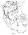
図1に示すように、例示的な電極システム(10)は、ヘッドセット(20)、および制御ボックス(40)を含む。ヘッドセット(20)は、ヘッドフレーム(24)、および複数の電極モジュール(100)を含む。本実施例のヘッドセット(20)は、8個の電極モジュール(100)を含むが、他の任意の適切な数の電極モジュール(100)を使用してよいことが理解されるべきである。図1〜図3に示す電極モジュール(100)の配列は単に例示的なものであること、および、電極モジュール(100)が他の任意の適切な配列で位置付けられてよいことも理解されるべきである。電極モジュール(100)は、以下でさらに詳細に説明するように、ヘッドフレーム(24)と取り外し可能に連結される。
Example system overview
As shown in FIG. 1, an exemplary electrode system (10) includes a headset (20), and control box (40). Headset (20) includes a head frame (24), and a plurality of electrode module (100). The headset (20) of this example includes eight electrode modules (100), but it should be understood that any other suitable number of electrode modules (100) may be used. It should also be understood that the arrangement of electrode modules (100) shown in FIGS. 1-3 is merely exemplary and that the electrode modules (100) may be positioned in any other suitable arrangement. It is. The electrode module (100) is removably coupled to the head frame (24) as will be described in more detail below.
〔例示的なヘッドフレーム〕
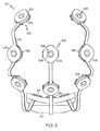
本実施例では、ヘッドフレーム(24)は、いくつかの弾性ひも(26)で形成され、電極モジュール(100)は、弾性ひも(26)の接合部でヘッドフレーム(24)に固定される。弾性ひも(26)の接合部は、環状スナップ部材(28)を含み、これらの環状スナップ部材はそれぞれ、中央部が開口している。以下でさらに詳細に説明するように、電極モジュール(100)の開口部(106)は、対応するスナップ部材(28)の開口中央部と整列して、挿入されたセンサー(200)を被験者の頭部に接触させるように構成される。いくつかのバージョンでは、弾性ひも(26)は、ゴムひも(elastic)で形成されるが、任意の他の適切な材料または材料の組み合わせを使用してよいことが理解されるべきである。本実施例のヘッドフレーム(24)は、被験者の頭部を実質的に包み込むように構成されるが、ヘッドフレーム(24)が任意の他の適切な構成を有し得ることも理解されるべきである。ほんの一例として、ヘッドフレーム(24)は、マサチューセッツ州ウェストフォードのHydroDot, Inc.による、EzeNet(登録商標)再利用可能ヘッドピースを含むことができる。EzeNet(登録商標)再利用可能ヘッドピースは、さまざまなサイズのものがあり、国際10−20法(international 10/20 system)の電極配置に一致することができる。
[Example head frame]
In this embodiment, the head frame (24) is formed of several elastic strings (26), and the electrode module (100) is fixed to the head frame (24) at the joint of the elastic strings (26). The joint of the elastic strap (26) includes an annular snap member (28), each of which is open at the center. As will be described in more detail below, the opening (106) of the electrode module (100) is aligned with the center of the opening of the corresponding snap member (28) to place the inserted sensor (200) in the subject's head. It is comprised so that a part may be contacted. In some versions, the elastic string (26) is formed of an elastic string, but it should be understood that any other suitable material or combination of materials may be used. Although the head frame (24) of this example is configured to substantially envelop the subject's head, it should also be understood that the head frame (24) may have any other suitable configuration. It is. By way of example only, the head frame (24) may include an EzeNet® reusable headpiece by HydroDot, Inc., Westford, Massachusetts. EzeNet® reusable headpieces come in a variety of sizes and can match the electrode arrangement of the international 10/20 system.
別の単に例示的な実施例として、ヘッドフレーム(24)は、開示内容が参照により本明細書に組み込まれる、「Evoked Response Testing System for Neurological Disorders」という名称の、2007年8月16日に公開された米国特許出願公開第2007/0191727号の教示に従って、かつ/もしくは、本明細書に挙げる任意の他の文献の教示に従って、構成されかつ/または動作可能であってよい。実際、本明細書中の教示を、米国特許出願公開第2007/0191727号の教示および/または本明細書に挙げる任意の他の文献の教示と組み合わせ得るさまざまな方法が、当業者には明らかとなるであろう。あるいは、ヘッドフレーム(24)は、任意の他の適切な構成および/または操作性を有することができる。ヘッドフレーム(24)の他の適切なバリエーションが、本明細書の教示を考慮すれば当業者に明らかとなるであろう。 As another merely illustrative example, head frame (24) was published on August 16, 2007, entitled “Evoked Response Testing System for Neurological Disorders”, the disclosure of which is incorporated herein by reference. May be configured and / or operable in accordance with the teachings of published US Patent Application Publication No. 2007/0191727 and / or according to the teachings of any other document listed herein. Indeed, those skilled in the art will appreciate the various ways in which the teachings herein can be combined with the teachings of US Patent Application Publication No. 2007/0191727 and / or any other literature cited herein. It will be. Alternatively, the head frame (24) can have any other suitable configuration and / or operability. Other suitable variations of the head frame (24) will be apparent to those skilled in the art in view of the teachings herein.
図1〜図3に示すように、電極モジュール(100)は、可撓性コネクタ(50)によって互いに物理的かつ通信的に連結されている。電極モジュール(100)は、可撓性コネクタ(50)により制御ボックスインターフェースモジュール(30)とも物理的かつ通信的に連結されている。本実施例の可撓性コネクタ(50)は、フレキシブル回路を含み、フレキシブル回路は、フレキシブル基板に形成されるトレース(不図示)を含む。あるいは、従来のワイヤまたは他の電線管を使用することができる。本実施例では、ヘッドセット(20)は、ケーブル(42)によって制御ボックス(40)と連結される。具体的には、制御ボックスインターフェースモジュール(30)は、ポート(32)を含み、これらのポートとケーブル(42)を連結することができる。制御ボックスインターフェースモジュール(30)はまた、ポート(32)によって可撓性コネクタ(50)とケーブル(42)との間に信号を送るように構成された回路を含む。よって、制御ボックスインターフェースモジュール(30)は、ケーブル(42)と可撓性コネクタ(50)との間に通信インターフェースをもたらすことができる。制御ボックスインターフェースモジュール(30)に組み込まれ得るさまざまな適切な構成要素、ならびにそのような構成要素のさまざまな適切な特徴部/機能性が、本明細書に挙げる文献に記載されている。ほんの一例として、制御ボックスインターフェースモジュール(30)は、米国特許出願公開第2007/0191727号のヘッドセット「制御モジュール12」の教示、および/または本明細書に挙げる任意の他の文献の教示に従って構成され、また動作可能であってよい。制御ボックスインターフェースモジュール(30)に組み込まれ得る、さらに他の適切な構成要素が、本明細書の教示を考慮すれば、当業者に明らかとなるであろう。 As shown in FIGS. 1 to 3, the electrode modules (100) are physically and communicatively coupled to each other by a flexible connector (50). The electrode module (100) is also physically and communicatively coupled to the control box interface module (30) by a flexible connector (50). The flexible connector (50) of the present embodiment includes a flexible circuit, and the flexible circuit includes a trace (not shown) formed on the flexible substrate. Alternatively, conventional wires or other conduits can be used. In this embodiment, a headset (20) is connected to the control box (40) by a cable (42). Specifically, the control box interface module (30) includes ports (32), and these ports can be connected to the cable (42). The control box interface module (30) also includes circuitry configured to send signals between the flexible connector (50) and the cable (42) by the port (32). Thus, the control box interface module (30) can provide a communication interface between the cable (42) and the flexible connector (50). Various suitable components that can be incorporated into the control box interface module (30), as well as various suitable features / functionality of such components, are described in the literature cited herein. By way of example only, control box interface module (30) is constructed in accordance with U.S. patent application teaches the headset Publication No. 2007/0191727, "control module 12", and / or teachings of any other references cited herein And may be operable. Still other suitable components that may be incorporated into the control box interface module (30) will be apparent to those skilled in the art in view of the teachings herein.
本実施例では、図2に示すように、制御ボックスインターフェースモジュール(30)はまた、フランジ部材(34)を含む。フランジ部材(34)は、制御ボックスインターフェースモジュール(30)をヘッドフレーム(24)と固定するように構成される。例えば、ヘッドフレーム(24)は、フランジ部材(34)を受容するよう構成された開口部を含むことができる。当然、制御ボックスインターフェースモジュール(30)は、制御ボックスインターフェースモジュール(30)がとにかくヘッドフレーム(24)に固定される範囲において、当業者には明らかとなるようなさまざまな他の方法で、ヘッドフレーム(24)に固定されることができる。さらに、制御ボックスインターフェースモジュール(30)は、いくつかのバージョンでは単に省略されてよい(例えば、ケーブル(42)が、自由にぶら下がる可撓性コネクタ(50)に直接連結するなど)。 In this embodiment, as shown in FIG. 2, the control box interface module (30) also includes a flange member (34). The flange member (34) is configured to secure the control box interface module (30) to the head frame (24). For example, the head frame (24) can include an opening configured to receive the flange member (34). Of course, the control box interface module (30) can be mounted in various other ways as will be apparent to those skilled in the art to the extent that the control box interface module (30) is fixed to the head frame (24) anyway. (24) can be fixed. Further, the control box interface module (30) may simply be omitted in some versions (eg, the cable (42) directly connects to a freely hanging flexible connector (50), etc.).
〔例示的な制御ボックス〕
本実施例の制御ボックス(40)は、さまざまな試験プロトコル(例えば、ERP試験プロトコルなど)を記憶するように構成された記憶媒体(不図示)と、ヘッドセット(20)を通じてそのような試験を実行するように構成されたプロセッサ(不図示)と、を含む。具体的には、制御ボックス(40)は、本実施例では、ケーブル(42)を通じて電力およびコマンドまたは他の種類の信号をヘッドセット(20)に与え、ヘッドセット(20)は、ケーブル(42)を通じてデータまたは他の種類の信号を制御ボックス(40)に送り返す。制御ボックス(40)はまた、電極モジュール(100)を通じて入手したデータを含むがこれに限定されない、このような試験中に収集されたデータを記憶するように動作可能である。このような電力、コマンド、データ、または他の種類の信号は、本明細書に記載するような、また、参照により本明細書に組み込まれる文献に記載するような、さまざまな種類のERP試験プロトコルに従って提供されることができる。
[Exemplary control box]
Control box (40) of the present example, the various test protocols (e.g., such as ERP testing protocol) configured storage medium to store (not shown), such tests through the headset (20) And a processor (not shown) configured to execute. More specifically, the control box (40), in this example, powered and commands or other types of signals through the cable (42) to the headset (20), a headset (20), the cable (42 ) To send data or other types of signals back to the control box (40). The control box (40) is also operable to store data collected during such testing, including but not limited to data obtained through the electrode module (100). Such power, command, data, or other types of signals may be transmitted through various types of ERP test protocols as described herein and as described in the literature incorporated herein by reference. Can be provided according to.
制御ボックス(40)は、ワイヤを通じて、かつ/または無線で、コンピューターシステム(不図示)と連結されるように構成される。例えば、コンピューターシステムは、試験プロトコル、コマンド、または他のデータを制御ボックス(40)に送信することができる。同様に、制御ボックス(40)は、コマンド、試験結果、または他のデータをコンピューターシステムに送信することができる。本実施例の制御ボックス(40)はまた、手持ち式となるように構成される。ほんの一例として、制御ボックス(40)は、ヘッドセット(20)を装着している被験者の手に、臨床医もしくは看護師の手に、または任意の他の人物の手に保持されることができる。前記に加え、または前記の代わりに、制御ボックス(40)は、米国特許出願公開第2007/0191727号を含むがこれに限定されない、本明細書に挙げる文献のいずれかに従って構成され、これに従って動作可能であり、かつ/またはこれに記載された同様の構成要素の任意の適切な特徴/機能性を有することができる。本明細書の教示を、本明細書に挙げた文献の教示に組み込むかまたは別様に組み合わせ得るさまざまな方法は、当業者に容易に明らかとなるであろう。 The control box (40) is configured to be coupled to a computer system (not shown) through wires and / or wirelessly. For example, the computer system can send a test protocol, command, or other data to the control box (40). Similarly, the control box (40) can send commands, test results, or other data to the computer system. The control box (40) of the present embodiment is also configured to be handheld. By way of example only, the control box (40) may be held in the hand of a subject wearing a headset ( 20 ), in the hands of a clinician or nurse, or in the hands of any other person. it can. In addition to or in lieu of the foregoing, the control box (40) may be configured and operated in accordance with any of the documents listed herein, including but not limited to US Patent Application Publication No. 2007/0191727. It can be and / or have any suitable features / functionality of similar components described therein. Various ways in which the teachings herein may be incorporated into or otherwise combined with the teachings of the references cited herein will be readily apparent to those skilled in the art.
2本のケーブル(42)が図示されているが、ただ1本のケーブル(42)を使用してよいことが理解されるべきである。電極システム(10)のいくつかの他のバージョンが、ケーブル(22)を有することに加え、またはその代わりに、無線で、ヘッドセット(20)への、かつ/またはヘッドセット(20)からの、電力、コマンド、データおよび/または他の種類の信号の通信を提供し得ることも、理解されるべきである。 Although two cables (42) are shown, it should be understood that only one cable (42) may be used. Several other versions of the electrode system (10), in addition to having a cable (22), or alternatively, by radio, to the headset (20), and / or from the headset (20) It should also be understood that communication of power, commands, data and / or other types of signals may be provided.
〔例示的な電極モジュール〕
本実施例では、電極システム(10)の電極モジュール(100)は、実質的に互いに同一である。したがって、以下の説明は、単に例として個々の電極モジュール(100)を説明している。しかしながら、所定の電極システム(10)が異なる種類の電極モジュール(100)を有してよいことが理解されるべきである。言い換えれば、所定の電極システム(10)内部の1つまたは複数の電極モジュール(100)は、同じ電極システム(10)内部の他の電極モジュール(100)の特徴部、構成要素、機能性などとは異なる、特徴部、構成要素、機能性などを有することができる。電極モジュール(100)間のこのような差異は、被験者の頭部または被験者の解剖学的構造の他の部分における電極モジュール(100)の場所を含むがこれに限定されない、さまざまな事柄に基づいていてよい。電極モジュール(100)を所定の電極システム(10)内部で互いと異ならせることができる適切な方法は、本明細書の教示を考慮すれば、当業者には明らかとなるであろう。あるいは、本実施例のように、所定の電極システム(10)内部の全ての電極モジュール(100)が、実質的に互いに同一であってもよい。
[Exemplary electrode module]
In this embodiment, the electrode modules (100) of the electrode system (10) are substantially identical to each other. Accordingly, the following description describes individual electrode modules (100) by way of example only. However, it should be understood that a given electrode system (10) may have different types of electrode modules (100). In other words, one or more electrode modules (100) within a given electrode system (10) can be characterized by features, components, functionality, etc. of other electrode modules (100) within the same electrode system (10). Can have different features, components, functionality, and the like. Such differences between the electrode modules (100) are based on a variety of things, including but not limited to the location of the electrode module (100) in the subject's head or other part of the subject's anatomy. It's okay. Appropriate methods by which the electrode modules (100) can differ from each other within a given electrode system (10) will be apparent to those skilled in the art in view of the teachings herein. Alternatively, as in this embodiment, all electrode modules (100) within a given electrode system (10) may be substantially identical to one another.
図2〜図7に示すように、電極モジュール(100)は、上方クラムシェル部材(102)、下方クラムシェル部材(104)、回路基板(130)、および伝導性リング(150)を含む。クラムシェル部材(102、104)は、成型プラスチックで、かつ/または任意の他の適切な材料および/もしくはプロセスを用いて、形成されてよい。図示のとおり、上方クラムシェル部材(102)、下方クラムシェル部材(104)、回路基板(130)、および伝導性リング(150)が全て、中央開口部(106)を画定している。具体的には、上方クラムシェル部材(102)、下方クラムシェル部材(104)、回路基板(130)、および伝導性リング(150)の中央開口部は全て、これらの構成要素が互いに組み立てられて電極モジュール(100)を形成したとき、同軸上に整列するように構成されており、組み立てられた電極モジュール(100)自体が、中央開口部(106)を画定する。この中央開口部(106)は、以下でさらに詳細に説明するセンサー(200)を挿入により受容するように構成される。さらに、これらの構成要素は、以下でより詳細に説明するように、伝導性リング(150)の一部が、組み立てられた電極モジュール(100)の中央開口部(106)の内径において露出されるように構成される。電極モジュール(100)の組み立て中、上方クラムシェル部材(102)は、超音波溶接、スナップ嵌め、接着剤、ファスナーなどを含むがこれらに限定されない、任意の適切な技術を用いて、下方クラムシェル部材(104)に固定されることができる。開口部(106)は、本実施例では、電極モジュール(100)のほぼ中央にあるが、開口部(106)が電極モジュール(100)の残り部分に対して中心を外すかまたは別様に位置してよいことが、理解されるべきである。 As shown in FIGS. 2-7, the electrode module (100) includes an upper clamshell member (102), a lower clamshell member (104), a circuit board (130), and a conductive ring (150). The clamshell members (102, 104) may be formed of molded plastic and / or using any other suitable material and / or process. As shown, the upper clamshell member (102), the lower clamshell member (104), the circuit board (130), and the conductive ring (150) all define a central opening (106). Specifically, the upper clamshell member (102), the lower clamshell member (104), the circuit board (130), and the central opening of the conductive ring (150) are all assembled together. When the electrode module (100) is formed, it is configured to be coaxially aligned, and the assembled electrode module (100) itself defines a central opening (106). This central opening (106) is configured to receive by insertion a sensor (200), described in more detail below. In addition, these components have portions of the conductive ring (150) exposed at the inner diameter of the central opening (106) of the assembled electrode module (100), as described in more detail below. Configured as follows. During assembly of the electrode module (100), the upper clamshell member (102) may be formed using any suitable technique, including but not limited to ultrasonic welding, snap fit, adhesive, fasteners, and the like. It can be fixed to the member (104). The opening (106) is approximately in the center of the electrode module (100) in this embodiment, but the opening (106) is off-centered or otherwise positioned relative to the rest of the electrode module (100). It should be understood that this may be done.
本実施例の上方クラムシェル部材(102)は、開口部(106)の周辺に、環状傾斜面(108)を呈する。環状傾斜面(108)は、以下でさらに詳細に説明するように、開口部(106)へのセンサー(200)の挿入を容易にするように構成される。当然、本明細書に記載する他の構成要素および特徴部と同じように、傾斜面(108)は、単にオプションである。本実施例の下方クラムシェル部材(104)は、上方に延びる第1対の支柱(110)、および上方に延びる第2対の支柱(112)を含む。下方クラムシェル部材(104)はまた、開口部(106)の周辺における環状リム(114)と、環状リム(114)に隣接した溝(116)と、を含む。下方クラムシェル部材(104)のこれらの特徴部はそれぞれ、以下でさらに詳細に説明する。 The upper clamshell member (102) of the present embodiment presents an annular inclined surface (108) around the opening (106). The annular ramp (108) is configured to facilitate insertion of the sensor (200) into the opening (106), as described in more detail below. Of course, as with other components and features described herein, the ramp (108) is merely optional. The lower clamshell member (104) of the present embodiment includes a first pair of struts (110) extending upward and a second pair of struts (112) extending upward. The lower clamshell member (104) also includes an annular rim (114) around the opening (106) and a groove (116) adjacent to the annular rim (114). Each of these features of the lower clamshell member (104) is described in further detail below.
本実施例の回路基板(130)は、一対の開口部(132)と、一対のコネクタ(134)と、を含む。図5〜図6に示すように、回路基板(130)の開口部(132)は、下方クラムシェル部材(104)の支柱(110)と整列し、それらを受容するように構成される。したがって、開口部(132)および支柱(110)は、回路基板(130)を下方クラムシェル部材(104)と適切に位置合わせすることを助け、また、回路基板(130)を下方クラムシェル部材(104)に対して固定することを助けることができる。当然、開口部(132)および支柱(110)は、回路基板(130)を、下方クラムシェル部材(104)に対して位置合わせし、固定し得る多くの異なる方法のうちの1つに過ぎない。回路基板(130)を下方クラムシェル部材(104)に対して位置合わせし、かつ/または固定するための、さまざまな他の構造体、特徴部、技術などが、本明細書の教示を考慮すれば、当業者には明らかとなるであろう。 The circuit board (130) of the present embodiment includes a pair of openings (132) and a pair of connectors (134). As shown in FIGS. 5-6, the opening (132) of the circuit board (130) is configured to align with and receive the posts (110) of the lower clamshell member (104). Thus, the openings (132) and struts (110) assist in properly aligning the circuit board (130) with the lower clamshell member (104) and also allow the circuit board (130) to align with the lower clamshell member ( 104) can be fixed. Of course, the opening (132) and post (110) are only one of many different ways in which the circuit board (130) can be aligned and secured to the lower clamshell member (104). . Various other structures, features, techniques, etc. for aligning and / or securing the circuit board (130) to the lower clamshell member (104) are contemplated in view of the teachings herein. Will be apparent to those skilled in the art.
回路基板(130)のコネクタ(134)は、可撓性コネクタ(50)と物理的かつ通信的に連結されるように構成される。具体的には、各コネクタ(134)は、対応する可撓性コネクタ(50)の自由端を受容するよう構成されたスロットを有する。可撓性コネクタ(50)は、下方クラムシェル部材(104)の支柱(112)を受容するように構成された開口部(52)を有する。よって、可撓性コネクタ(50)がコネクタ(134)のスロットに挿入され、支柱(112)が可撓性コネクタ(50)の開口部(52)を通して挿入されると、また、クラムシェル部材(102、104)が図7に示すように互いに対して固定されると、開口部(52)を通した支柱(112)の挿入は、可撓性コネクタ(50)がコネクタ(134)から引き抜かれることを実質的に妨げることができる。さらに、コネクタ(134)は、そのスロット内部に、1つまたは複数の露出した/露出可能な電気接触子を有してよく、可撓性コネクタ(50)の自由端は、コネクタ(134)のスロット内部の1つまたは複数の露出した/露出可能な電気接触子に接触するように位置付けられた、1つまたは複数の対応する電気接触子を有することができる。ゆえに、コネクタ(134)は、電力、コマンド、データ、他の信号などを、可撓性コネクタ(50)の1つまたは複数のトレースに、かつ/またはそのトレースから、通信することができる。 The connector (134) of the circuit board (130) is configured to be physically and communicatively coupled to the flexible connector (50). Specifically, each connector (134) has a slot configured to receive the free end of the corresponding flexible connector (50). The flexible connector (50) has an opening (52) configured to receive the strut (112) of the lower clamshell member (104). Thus, when the flexible connector (50) is inserted into the slot of the connector (134) and the post (112) is inserted through the opening (52) of the flexible connector (50), the clamshell member ( 102, 104) are secured to each other as shown in FIG. 7, insertion of the strut (112) through the opening (52) causes the flexible connector (50) to be withdrawn from the connector (134). This can be substantially prevented. In addition, the connector (134) may have one or more exposed / exposable electrical contacts within its slot, and the free end of the flexible connector (50) is connected to the connector (134). There may be one or more corresponding electrical contacts positioned to contact one or more exposed / exposed electrical contacts within the slot. Thus, the connector (134) can communicate power, commands, data, other signals, etc. to and / or from one or more traces of the flexible connector (50).
当然、コネクタ(134)は単なるオプションであり、コネクタ(134)は、所望に応じて、改変、置換、補足、または省略されることができる。ほんの一例として、いくつかの代替的なバージョンは、全ての可撓性コネクタ(50)および回路基板(130)を、単一の一体的なリジッド−フレックス回路(rigid-flex circuit)として形成することにより、コネクタ(134)全体を省略している。このようなリジッド−フレックス回路の単に例示的な例は、「Electrode System with Rigid-Flex Circuit」という名称の、2009年9月25日に出願された米国仮特許出願第61/245,686号に開示されており、この開示内容は参照により本明細書に組み込まれる。コネクタ(134)を改変、置換、補足、または省略し得るさらに他の適切な方法は、本明細書の教示を考慮すれば当業者には明らかであろう。 Of course, connector (134) is merely an option, and connector (134) may be modified, replaced, supplemented, or omitted as desired. By way of example only, some alternative versions form all flexible connectors (50) and circuit boards (130) as a single, integral rigid-flex circuit. Thus, the entire connector (134) is omitted. A merely illustrative example of such a rigid-flex circuit is in US Provisional Patent Application No. 61 / 245,686, filed September 25, 2009, entitled “Electrode System with Rigid-Flex Circuit”. The disclosure of which is incorporated herein by reference. Still other suitable ways in which the connector (134) may be modified, replaced, supplemented, or omitted will be apparent to those skilled in the art in view of the teachings herein.
図1〜図3に示すように、また前記のとおり、電極モジュール(100)は、可撓性コネクタ(50)により連結される。いくつかのバージョンでは、異なる電極モジュール(100)が、そのような可撓性コネクタ(50)に沿ってそれら自体の専用トレースを有する。所定の電極モジュール(100)の専用トレースは、別の所定の電極モジュール(100)の専用トレースと同じ長さの可撓性コネクタ(50)の一部に沿って延びてよい。例えば、1つの電極モジュール(100)の1組の専用トレースが、所定の可撓性コネクタ(50)におけるフレキシブル回路の1つの層上に設けられてよく、一方、別の電極モジュール(100)の1組の専用トレースが、同じ可撓性コネクタ(50)におけるフレキシブル回路の別の層上に設けられてよく、これらの層は双方、同じ可撓性コネクタ(50)のフレキシブル回路の共通の長さに沿って延びている。単に例示的な別の例としては、1つの電極モジュール(100)の専用トレースは、別の電極モジュール(100)の専用トレースと同じ、フレキシブル回路の層上に設けられてよく、別々の組のトレースが、共通の層上で幾何学的に平行となる。他のいくつかのバージョンでは、異なる電極モジュール(100)が、所定の可撓性コネクタ(50)において1つまたは複数の共通トレースを共有してもよい。ほんの一例として、可撓性コネクタ(50)のフレキシブル回路における1つまたは複数のトレースはバス伝送に使用されてよく、異なる電極モジュール(100)に関する情報が、バス上に組み合わせられ、2つ以上の電極モジュール(100)と通信している1つまたは複数の非専用トレースに沿って通信されることができる。トレースまたは他の通信特徴部を使用、提供、配列などすることができる、他のさまざまな適切な方法は、本明細書の教示を考慮すれば、当業者には明らかであろう。 As shown in FIGS. 1 to 3 and as described above, the electrode module (100) is connected by the flexible connector (50). In some versions, different electrode modules (100) have their own dedicated traces along such a flexible connector (50). A dedicated trace of a given electrode module (100) may extend along a portion of a flexible connector (50) that is the same length as a dedicated trace of another given electrode module (100). For example, a set of dedicated traces of one electrode module (100) may be provided on one layer of flexible circuitry in a given flexible connector (50), while another electrode module (100) a set of dedicated trace may be provided on another layer of the flexible circuit in the same friendly fLEXIBLE connector (50), these layers are both the same flexible connector common flexible circuit (50) It extends along the length. As just another illustrative example, the dedicated traces of one electrode module (100) may be provided on the same layer of flexible circuitry as the dedicated traces of another electrode module (100), and a separate set of The traces are geometrically parallel on the common layer. In some other versions, different electrode modules (100) may share one or more common traces in a given flexible connector (50). By way of example only, one or more traces in the flexible circuit of the flexible connector (50) may be used for bus transmission, and information about different electrode modules (100) may be combined on the bus to combine two or more It can be communicated along one or more non-dedicated traces that are in communication with the electrode module (100). Various other suitable ways in which traces or other communication features may be used, provided, arranged, etc. will be apparent to those skilled in the art in view of the teachings herein.
本実施例の各電極モジュール(100)の回路基板(130)はまた、感知回路(不図示)を含み、この感知回路は、いくつかある構成要素のうち特に増幅器を含む。このような感知回路は、回路基板(130)のコネクタ(134)と通信しており、感知回路は、可撓性コネクタ(50)の1つまたは複数のトレースと通信することができる。本実施例では増幅器を含む回路基板(130)の感知回路があるので、電極モジュール(100)がアクティブであることが理解されるべきである。そのような感知回路は、参照により開示内容が本明細書に組み込まれる、「Active, Multiplexed Digital Electrodes for EEG, ECG, and EMG Applications」という名称の、2005年9月29日に公開された米国特許出願公開第2005/0215916号の教示に従って、および/もしくは本明細書に挙げる任意の他の文献の教示に従って、構成され、かつ/または動作可能であることができる。実際、本明細書の教示を、米国特許出願公開第2005/0215916号の教示および/または本明細書に挙げる任意の他の文献の教示と組み合わせ得るさまざまな方法が、当業者には明らかであろう。あるいは、回路基板(130)の感知回路は、任意の他の適切な構成および/または操作性を有してよい。例えば、回路基板(130)のいくつかのバージョンには、増幅器がなくてもよく、このため電極モジュール(100)はアクティブではない。感知回路のさまざまな形態および構成要素を含むがこれらに限定されない、回路基板(130)を構成し得るさらに他の適切な方法は、本明細書の教示を考慮すれば、当業者には明らかであろう。 The circuit board (130) of each electrode module (100) of this embodiment also includes a sensing circuit (not shown), which includes an amplifier, among other components. Such a sensing circuit is in communication with a connector (134) on the circuit board (130), and the sensing circuit can be in communication with one or more traces of the flexible connector (50). It should be understood that the electrode module (100) is active because there is a sensing circuit on the circuit board (130) that includes an amplifier in this embodiment. Such a sensing circuit is a U.S. patent published September 29, 2005 entitled "Active, Multiplexed Digital Electrodes for EEG, ECG, and EMG Applications", the disclosure of which is incorporated herein by reference. It may be configured and / or operable in accordance with the teachings of published application 2005/0215916 and / or in accordance with the teachings of any other document listed herein. Indeed, various ways in which the teachings herein can be combined with the teachings of US Patent Application Publication No. 2005/0215916 and / or any other literature cited herein will be apparent to those skilled in the art. Let's go. Alternatively, the sensing circuit of the circuit board (130) may have any other suitable configuration and / or operability. For example, some versions of the circuit board (130) may not have an amplifier so that the electrode module (100) is not active. Still other suitable ways of constructing the circuit board (130), including but not limited to various forms and components of the sensing circuit, will be apparent to those skilled in the art in view of the teachings herein. I will.
本実施例では、伝導性リング(150)は、半径方向外側に延びる尾部(152)を含む。伝導性リング(150)は、下方クラムシェル部材(104)の環状リム(114)に載るように構成され、尾部(152)が下方クラムシェル部材(104)の溝(116)を通って突出する。したがって、環状リム(114)、溝(116)、および尾部(152)は、伝導性リング(150)を下方クラムシェル部材(104)と適切に位置合わせすることを助け、また、伝導性リング(150)を下方クラムシェル部材(104)に対して固定することを助けるよう、協働する。当然、これらの特徴部は単なる例であり、伝導性リング(150)を下方クラムシェル部材(104)に対して位置合わせおよび/または固定するための、さまざまな他の構造体、特徴部、技術などが、本明細書の教示を考慮すれば、当業者には明らかであろう。図7で最もよく見ることができるように、上方クラムシェル部材(102)は、伝導性リング(150)上に位置付け可能で、伝導性リング(150)をクラムシェル部材(102、104)間に「挟む」ことにより伝導性リング(150)を所定の場所にさらに固定する。前記のとおり、伝導性リング(150)の一部が、組み立てられた電極モジュール(100)の中央開口部(106)の内径において依然として露出されている(例えば、上方クラムシェル部材(102)が下方クラムシェル部材(104)に固定された場合など)。伝導性リング(150)はまた、(例えば尾部(152)を通じた接触などにより)回路基板(130)の感知回路と通信連結する。特に、伝導性リング(150)は、以下でさらに詳細に説明するように、ERP信号を回路基板(130)の感知回路に通信するように構成される。 In this example, the conductive ring (150) includes a tail (152) extending radially outward. The conductive ring (150) is configured to rest on the annular rim (114) of the lower clamshell member (104), with the tail (152) protruding through the groove (116) of the lower clamshell member (104). . Thus, the annular rim (114), groove (116), and tail (152) assist in properly aligning the conductive ring (150) with the lower clamshell member (104), and the conductive ring ( 150) cooperate to help secure the lower clamshell member (104). Of course, these features are merely examples, and various other structures, features, techniques for aligning and / or securing the conductive ring (150) to the lower clamshell member (104). Etc. will be apparent to one of ordinary skill in the art in view of the teachings herein. As can best be seen in FIG. 7, the upper clamshell member (102) can be positioned on the conductive ring (150) so that the conductive ring (150) is between the clamshell members (102, 104). The conductive ring (150) is further fixed in place by “pinching”. As described above, a portion of the conductive ring (150) is still exposed at the inner diameter of the central opening (106) of the assembled electrode module (100) (eg, the upper clamshell member (102) is lower) For example, when fixed to the clamshell member (104). The conductive ring (150) is also in communication communication with the sensing circuitry of the circuit board (130) (eg, by contact through the tail (152)). In particular, the conductive ring (150) is configured to communicate an ERP signal to a sensing circuit on the circuit board (130), as will be described in more detail below.
電極モジュール(100)は、さまざまな方法でヘッドフレーム(24)と連結されてよい。本実施例では、電極モジュール(100)は、ヘッドフレーム(24)のスナップ部材(28)においてスナップ部品(snap fittings)によりヘッドフレーム(24)と連結される。例えば、図5〜図7に示すように、本実施例の各電極モジュール(100)は、スナップアダプタ(170)を備えている。各スナップアダプタ(170)は、上方フランジ(172)、下方フランジ(174)、および上方フランジ(172)と下方フランジ(174)との間に垂直に延びる円筒状部分(176)を含む。下方クラムシェル部材(104)は、図7に示すようにスナップアダプタ(170)の上方フランジ(172)をスナップ式に(snappingly)受容するように構成された環状凹部(118)を含む。したがって、スナップアダプタ(170)は、本実施例ではスナップ部品を通じて電極モジュール(100)と連結するが、スナップアダプタ(170)を電極モジュール(100)と固定するために、任意の他の適切な特徴部、構成要素、技術などを使用し得ることが、理解されるべきである。あるいは、電極モジュール(100)は、一体的または単一のスナップアダプタを有してもよく、または、何らかの他の方法でヘッドフレーム(24)と連結することができる。 The electrode module (100) may be coupled to the head frame (24) in various ways. In this embodiment, the electrode module (100) is connected to the head frame (24) by snap fittings at the snap member (28) of the head frame (24). For example, as shown in FIGS. 5 to 7, each electrode module (100) of the present embodiment includes a snap adapter (170). Each snap adapter (170) includes an upper flange (172), a lower flange (174), and a cylindrical portion (176) extending vertically between the upper flange (172) and the lower flange (174). The lower clamshell member (104) includes an annular recess (118) configured to snappingly receive the upper flange (172) of the snap adapter (170) as shown in FIG. Thus, although the snap adapter (170) is coupled to the electrode module (100) through a snap piece in this embodiment, any other suitable feature may be used to secure the snap adapter (170) to the electrode module (100). It should be understood that parts, components, techniques, etc. may be used. Alternatively, the electrode module (100) may have an integral or single snap adapter or may be coupled to the head frame (24) in some other manner.
本実施例では、パッド(160)が、各スナップアダプタ(170)に固定される。各パッド(160)は、外側に延びる複数のタブ(162)を有しており、比較的柔軟である。例えば、パッド(160)の構成により、電極モジュール(100)が被験者の頭部上にある間に臨床医が電極モジュール(100)を操作する際の、被験者に対する不快感を減少させることができる。パッド(160)は、スナップアダプタ(170)の円筒状部分(176)の周りに嵌まるように構成される。図7に示すように、パッド(160)は、下方クラムシェル部材(104)の下面と、下方フランジ(174)の上面との間に「挟まれている」。当然、パッド(160)は、さまざまな他の方法で電極モジュール(100)と連結されてよい。ほんの一例として、パッド(160)は、1つまたは複数のクリップ、面ファスナー、接着剤等によって、電極モジュールに固定されることができる。あるいは、パッド(160)は、完全に省略されてもよい。例えば、ヘッドフレーム(24)のスナップ部材(28)は、スナップアダプタ(170)の円筒状部分(176)周辺に位置付けられてよい。したがって、スナップ部材(28)は、図7のパッド(160)と同様に、下方クラムシェル部材(104)の下面と、下方フランジ(174)の上面との間に挟まれることができる。しかしながら、本実施例では、スナップアダプタ(170)は、(例えばスナップ部材(28)の少なくとも一部が下方フランジ(174)より下に位置付けられるように)スナップ部材(28)とスナップ式に係合する。 In this embodiment, the pad (160) is fixed to each snap adapter (170). Each pad (160) has a plurality of outwardly extending tabs (162) and is relatively flexible. For example, the configuration of the pad (160) can reduce discomfort to the subject when the clinician operates the electrode module (100) while the electrode module (100) is on the subject's head. The pad (160) is configured to fit around the cylindrical portion (176) of the snap adapter (170). As shown in FIG. 7, the pad (160) is “sandwiched” between the lower surface of the lower clamshell member (104) and the upper surface of the lower flange (174). Of course, the pad (160) may be coupled to the electrode module (100) in a variety of other ways. By way of example only, the pad (160) can be secured to the electrode module by one or more clips, hook- and- loop fasteners , adhesives, and the like. Alternatively, the pad (160) may be omitted completely. For example, the snap member (28) of the head frame (24) may be positioned around the cylindrical portion (176) of the snap adapter (170). Accordingly, the snap member (28) can be sandwiched between the lower surface of the lower clamshell member (104) and the upper surface of the lower flange (174), similar to the pad (160) of FIG. However, in this embodiment, the snap adapter (170) snaps into engagement with the snap member (28) (eg, so that at least a portion of the snap member (28) is positioned below the lower flange (174)). To do.
単に例示的なさらに別のバリエーションとして、スナップアダプタ(170)は単に省略されてもよい。ほんの一例として、スナップ部材(28)は、それ自体が、下方クラムシェル部材(104)とスナップ式に係合してもよい。例えば、スナップ部材(28)は、下方クラムシェル部材(104)の環状凹部(188)にスナップ式に受容される、外側に延びる環状フランジを含むことができる。単に例示的なさらに別のバリエーションとしては、電極モジュール(100)は、ヘッドフレーム(24)と直接連結してもよく、電極モジュール(100)をヘッドフレーム(24)と連結するのにいかなるスナップ部品も使用されない。ほんの一例として、電極モジュール(100)は、1つまたは複数のクリップ、面ファスナー、接着剤等により、ヘッドフレーム(24)と連結され得る。さらに、電極モジュール(100)は、本実施例ではヘッドフレーム(24)と取り外し可能に連結されるが、電極モジュール(100)は、いくつかの他のバージョンでは、ヘッドフレーム(24)に対して永続的に付着されてもよい。 As yet another exemplary variation only, the snap adapter (170) may simply be omitted. By way of example only, the snap member (28) may itself snap into engagement with the lower clamshell member (104). For example, the snap member (28) may include an outwardly extending annular flange that is snapped into the annular recess (188) of the lower clamshell member (104). As yet another exemplary variation only, the electrode module (100) may be directly connected to the head frame (24), and any snap piece to connect the electrode module (100) to the head frame (24). Also not used. By way of example only, the electrode module (100) may be coupled to the head frame (24) by one or more clips, hook- and- loop fasteners , adhesives, and the like. Furthermore, although the electrode module (100) is removably coupled with the head frame (24) in this embodiment, the electrode module (100) is in some other versions relative to the head frame (24). It may be permanently attached.
いくつかのスナップ部材(28)(または他のタイプの電極モジュール(100)係合構造体)および弾性ひも(26)がヘッドフレーム(24)を提供するように配列された場合に、いくつかのスナップ部材(28)には、対応する電極モジュール(100)が連結されていなくてよいことも、理解されるべきである。したがって、いくつかのヘッドセット(20)が、異なる数および/または配列の電極モジュール(100)を有する異なる種類の電極システムに適応するように構成されてよく、ある程度のモジュール性をもたらすことが、理解されるべきである。電極モジュール(100)をヘッドセット(20)に組み込み得る、さらに他の適切な方法は、本明細書の教示を考慮すれば、当業者に明らかとなるであろう。 When several snap members (28) (or other type of electrode module (100) engagement structure) and elastic straps (26) are arranged to provide the head frame (24), It should also be understood that the corresponding electrode module (100) may not be coupled to the snap member (28). Thus, some of the headset (20) may be configured to accommodate different types of electrode system with a different number and / or sequence electrode modules (100), to result in some degree of modularity, Should be understood. Still other suitable methods by which the electrode module (100) can be incorporated into the headset (20) will be apparent to those skilled in the art in view of the teachings herein.
〔例示的なセンサー〕
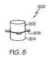
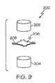
図5および図8〜図9に示すように、本実施例の電極システム(10)は、取り外し可能なセンサー(200)をさらに含む。本実施例の取り外し可能なセンサー(200)はそれぞれ、絶縁上部(202)、電解ヒドロゲルの下部(204)、および上部(202)と下部(204)との間に位置付けられた伝導性の中央部(206)を含む。伝導性の中央部(206)は、外側に延びる複数の伝導性タブ(208)を含む。各センサー(200)は、対応する電極モジュール(100)の中央開口部(106)に挿入されて、その中央開口部にぴったり嵌まるように構成される。いくつかの状況では、電極システム(10)の各電極モジュール(100)が、その中に挿入される、関連する取り外し可能なセンサー(200)を有するが、いくつかの電極モジュール(100)には、いくつかの状況で、関連する電極モジュール(100)がなくてもよい。開口部(106)の周辺部における上方クラムシェル部材(102)の傾斜面(108)は、センサー(200)を開口部に案内することなどにより、開口部(106)へのセンサー(200)の挿入を容易にすることができる。当然、本明細書に記載する他の特徴部と同様、傾斜面(108)は単にオプションであり、所望に応じて、改変、置換、補足、または省略されてよい。
[Example sensor]
As shown in FIGS. 5 and 8-9, the electrode system (10) of the present example further includes a removable sensor (200). Each removable sensor (200) of this example has an insulating top (202), an electrolytic hydrogel bottom (204), and a conductive center located between the top (202) and bottom (204). (206). The conductive central portion (206) includes a plurality of conductive tabs ( 208 ) extending outward. Each sensor (200) is configured to be inserted into the central opening (106) of the corresponding electrode module (100) and fit snugly therewith. In some situations, each electrode module (100) of the electrode system (10) has an associated removable sensor (200) inserted therein, but some electrode modules (100) include In some situations, there may be no associated electrode module (100). The inclined surface (108) of the upper clamshell member (102) at the periphery of the opening (106) causes the sensor (200) to move to the opening (106), such as by guiding the sensor (200) to the opening. Insertion can be facilitated. Of course, like the other features described herein, the ramp (108) is merely optional and may be modified, replaced, supplemented, or omitted as desired.
取り外し可能なセンサー(200)が電極モジュール(100)に挿入され、対応するヘッドフレーム(24)が被験者の頭部に固定されると、取り外し可能なセンサー(200)は、電解ヒドロゲルの下部(204)が被験者の頭皮に接触するように構成される。例えば、センサー(200)は、絶縁上部(202)が上方クラムシェル部材(102)の傾斜面(108)に、またはその近くに垂直に位置付けられている間に、ヒドロゲルの下部(204)がスナップアダプタ(170)の下方フランジ(174)より下に突出するような高さを有してよい。あるいは、センサー(200)は、任意の他の適切な寸法を有することができる。さらに、所定の電極モジュール(100)の位置付けに応じて、関連する電解ヒドロゲルの下部(204)は、被験者の頭部または身体のどこか他の部分に接触することができる。例えば、ヒドロゲルの下部(204)は、単に、被験者の頭部の毛髪に接触してよく、センサー(200)が、被験者の頭皮に必ずしも接触せずに、被験者の頭部の毛髪のみに接触する場合であっても、電極システム(10)は、依然として適切に作動することができる。電解ヒドロゲルの下部(204)の電解特性のため、電解ヒドロゲルの下部(204)は、被験者の(例えば患者の)皮膚から、電圧または信号(例えばERP信号など)を受け取ることができる。ヒドロゲル自体が被験者の頭部に十分に付着できると共に、取り外し可能なセンサー(200)を比較的容易に被験者の頭部から引き離すことができるので、電解ヒドロゲルの下部(204)は、被験者の頭部に貼り付けられるかまたは接着される必要なく、データを収集することができる。 When the removable sensor (200) is inserted into the electrode module (100) and the corresponding head frame (24) is secured to the subject's head, the removable sensor (200) is placed under the electrolytic hydrogel (204). ) Is configured to contact the subject's scalp. For example, the sensor (200) has a hydrogel lower portion (204) snapped while the insulating upper portion (202) is positioned vertically at or near the inclined surface (108) of the upper clamshell member (102). It may have a height that projects below the lower flange (174) of the adapter (170). Alternatively, the sensor (200) can have any other suitable dimensions. Further, depending on the positioning of a given electrode module (100), the lower part (204) of the associated electrolytic hydrogel can contact the subject's head or some other part of the body. For example, the lower portion (204) of the hydrogel may simply contact the hair of the subject's head, and the sensor (200) contacts only the hair of the subject's head, not necessarily the subject's scalp. Even then, the electrode system (10) can still operate properly. Due to the electrolytic properties of the lower part (204) of the electrolytic hydrogel, the lower part (204) of the electrolytic hydrogel can receive a voltage or signal (eg, an ERP signal) from the subject's (eg, patient's) skin. Since the hydrogel itself can adhere well to the subject's head and the removable sensor (200) can be pulled away from the subject's head relatively easily, the lower portion (204) of the electrolytic hydrogel can be attached to the subject's head. Data can be collected without having to be affixed or glued to.
前記のとおり、本実施例のタブ(208)は、絶縁上部(202)と電解ヒドロゲルの下部(204)との間に配される伝導性部材(206)の一体的延長部として形成される。伝導性部材(206)およびタブ(208)は、タブ(208)が、図5および図8〜図9に示すように、半径方向外側に延びる向きをとるよう弾性的に付勢されるように、構成されている。センサー(200)が電極モジュール(100)の開口部(106)に挿入されると、タブ(208)は、図7に示すように開口部(106)の内径において露出される伝導性リング(150)に接触することが理解されるべきである。例えば、タブ(208)は、センサー(200)が開口部(106)に挿入されたときに、伝導性リング(150)に弾性的にもたれかかることができる。タブ(208)と伝導性リング(150)との間のそのような接触により、以下でさらに詳細に説明するような、伝導性部材(206)から伝導性リング(150)への通信経路がもたらされ得る。さらに、絶縁上部(202)および/もしくはヒドロゲルの下部(204)のエラストマー特性または他の特性は、センサー(200)を電極モジュールの開口部(106)に保持することを助け得る。さらに、または代替案では、センサー(200)は、開口部(106)に対してサイズが大きくてよく、センサー(200)が、開口部(106)にぴったりと、または干渉的に(interferingly)嵌まる。センサー(200)を開口部(106)に実質的に保持し得る他の方法は、本明細書の教示を考慮すれば、当業者には明らかであろう。 As described above, the tab (208) of this example is formed as an integral extension of the conductive member (206) disposed between the insulating top (202) and the bottom (204) of the electrolytic hydrogel. The conductive member (206) and the tab (208) are elastically biased so that the tab (208) is oriented radially outward as shown in FIGS. 5 and 8-9. ,It is configured. When the sensor (200) is inserted into the opening (106) of the electrode module (100), the tab (208) is exposed at the inner diameter of the opening (106) as shown in FIG. ) Should be understood. For example, the tab (208) can rest elastically against the conductive ring (150) when the sensor (200) is inserted into the opening (106). Such contact between the tab (208) and the conductive ring (150) also creates a communication path from the conductive member (206) to the conductive ring (150), as described in more detail below. Can be done. Further, the elastomeric or other properties of the insulating top (202) and / or the hydrogel bottom (204) may help hold the sensor (200) in the opening (106) of the electrode module. Additionally or alternatively, the sensor (200) may be larger in size relative to the opening (106) so that the sensor (200) fits snugly or interferingly with the opening (106). Maru. Other ways in which the sensor (200) can be substantially retained in the opening (106) will be apparent to those skilled in the art in view of the teachings herein.
伝導性部材(206)およびタブ(208)は、銀−塩化銀(silver-silver chloride)および/または任意の他の適切な材料から形成されてよい。伝導性リング(150)も、銀−塩化銀および/または任意の他の適切な材料で形成されてよい。伝導性部材(206)およびタブ(208)が電解ヒドロゲルの下部(204)と直接接触しているので、電解ヒドロゲルの下部(204)により受け取られる電圧または信号は、タブ(208)へ、そしてタブ(208)を通ってさらに通信され得ることが、理解されるべきである。センサー(100)が電極モジュール(100)の開口部(106)に挿入されたときにタブ(208)が伝導性リング(150)と接触しているので、タブ(208)は、電解ヒドロゲルの下部(204)により受け取られた電圧または信号を伝導性リング(150)に通信することができ、伝導性リング(150)は、次に、そのような電圧または信号を、回路基板(130)の感知回路に通信することができる。回路基板(130)(または他の場所)の増幅器が信号を増幅してよく、感知回路内部の他の構成要素が、必要であれば、信号の他の処理を行ってよく、その信号は次に、1つまたは複数の可撓性コネクタ(50)のフレキシブル回路を経由して電極モジュール(100)から離れて通信されることができる。よって、信号は、最終的に、可撓性コネクタ(50)によって制御ボックスインターフェースモジュール(30)へ、そして、その後、ケーブル(42)によって制御ボックス(40)へと、通信され得る。 Conductive member (206) and tabs (208), a silver - may be formed from silver chloride (silver-silver chloride) and / or any other suitable material. Conductive ring (150) also, silver - may be formed by silver chloride and / or any other suitable material. Since the conductive member (206) and the tab (208) are in direct contact with the lower portion (204) of the electrolytic hydrogel, the voltage or signal received by the lower portion (204) of the electrolytic hydrogel is transferred to the tab (208) and to the tab. It should be understood that further communications can be made through (208). Since the tab (208) is in contact with the conductive ring (150) when the sensor (100) is inserted into the opening (106) of the electrode module (100), the tab (208) is the lower part of the electrolytic hydrogel. The voltage or signal received by (204) can be communicated to the conductive ring (150), which then transmits such voltage or signal to the sensing of the circuit board (130). Can communicate with the circuit. An amplifier on the circuit board (130) (or elsewhere) may amplify the signal, and other components within the sensing circuit may perform other processing of the signal, if desired, In addition, it can be communicated away from the electrode module (100) via the flexible circuit of one or more flexible connectors (50). Thus, the signal can ultimately be communicated to the control box interface module (30) by the flexible connector (50) and then to the control box (40) by the cable (42).
いくつかのバージョンでは、取り外し可能なセンサー(200)は、マサチューセッツ州ウェストフォードのHydroDot, Inc.によるHydroDot(登録商標) Disposable EEG Electrodes またはHydroDot(登録商標) Biosensorsを含む。HydroDot(登録商標) Disposable EEG Electrode Application Systemのさまざまな態様が、参照により本明細書に組み込まれる、「EEG Headpiece with Disposable Electrodes and Apparatus and System and Method for Use Therewith」という名称の、1996年1月2日に発行された米国特許第5,479,934号で論じられている。当然、取り外し可能なセンサー(200)を含むがこれらに限定されない、電極システム(10)のさまざまな構成要素が、米国特許第5,479,934号中の任意の適切な教示に従って、構成、改変され、かつ/または動作可能となることができる。実際、本明細書の教示を、米国特許第5,479,934号の教示と組み合わせ得るさまざまな方法が、当業者には明らかであろう。取り外し可能なセンサー(200)は、全てのバージョンで必ずしも必要ではないことも、理解されるべきである。例えば、電極モジュール(100)は、注入可能ゲルを通じて、または任意の他の適切な方法で、被験者の頭部との電気的インターフェース、ならびに/または、被験者の頭部および/もしくは他の身体部分との何か他のタイプのインターフェースを有するように、構成されてよい。 In some versions, the removable sensor (200) comprises a HydroDot® Disposable EEG Electrodes or HydroDot® Biosensors by HydroDot, Inc., Westford, Massachusetts. Various aspects of the HydroDot® Disposable EEG Electrode Application System, named “EEG Headpiece with Disposable Electrodes and Apparatus and System and Method for Use Therewith”, January 2, 1996, incorporated herein by reference. Discussed in U.S. Pat. No. 5,479,934, issued on a daily basis. Of course, various components of the electrode system (10), including but not limited to the removable sensor (200), can be configured, modified in accordance with any suitable teachings in US Pat. No. 5,479,934. And / or can be operable. Indeed, various ways in which the teachings herein can be combined with the teachings of US Pat. No. 5,479,934 will be apparent to those skilled in the art. It should also be understood that the removable sensor (200) is not necessary in all versions. For example, the electrode module (100) may be electrically interfaced with the subject's head and / or through the injectable gel or in any other suitable manner and / or with the subject's head and / or other body parts. It may be configured to have some other type of interface.
本実施例のセンサー(200)は、実質的に円筒状の形状を有するが、センサー(200)は、代わりに任意の他の形状を有してよいことが理解されるべきである。ほんの一例として、センサー(200)は、立方体形状、垂直立方体形状(right cuboidal shape)、円錐形状、切頭円錐形状、ピラミッド形状、球体形状、および/または任意の他の適切な形状を有することができる。同様に、本実施例の伝導性リング(150)は実質的に円の形状を有するが、伝導性リング(150)は、代わりに任意の他の形状を有してもよいことが理解されるべきである。ほんの一例として、伝導性リング(150)は、正方形、長方形、三角形、および/または任意の他の適切な形状を有してよい。センサー(200)および伝導性リング(150)のさらに他の適切な構成、ならびにセンサー(200)と伝導性リング(150)との間のさらに他の適切な関係は、本明細書の教示を考慮すれば当業者には明らかとなるであろう。 Although the sensor (200) of the present example has a substantially cylindrical shape, it should be understood that the sensor (200) may instead have any other shape. By way of example only, the sensor (200) may have a cube shape, a right cube shape, a cone shape, a truncated cone shape, a pyramid shape, a sphere shape, and / or any other suitable shape. it can. Similarly, although the conductive ring (150) of the present example has a substantially circular shape, it is understood that the conductive ring (150) may instead have any other shape. Should. By way of example only, the conductive ring (150) may have a square, rectangular, triangular, and / or any other suitable shape. Still other suitable configurations of sensor (200) and conductive ring (150), as well as other suitable relationships between sensor (200) and conductive ring (150), are contemplated by the teachings herein. This will be apparent to those skilled in the art.
本実施例では、電極システム(10)は、8個の電極モジュール(100)を含む。単に例示的な別の実施例として、電極システム(10)は、23個の電極モジュール(100)を含むことができる。当然、電極システム(10)は、代わりに、任意の他の適切な数の電極モジュール(100)を含むこともできる。電極モジュール(100)はさまざまな方法で配列され得ることも理解されるべきである。ほんの一例として、さまざまな適切な配列が、本明細書に挙げる文献に開示されている。 In this embodiment, the electrode system (10) includes eight electrode modules (100). By way of example only, the electrode system (10) may include 23 electrode modules (100). Of course, the electrode system (10) may alternatively include any other suitable number of electrode modules (100). It should also be understood that the electrode module (100) can be arranged in various ways. By way of example only, a variety of suitable sequences are disclosed in the literature cited herein.
電極システム(10)を用いて入手した信号は、「Biopotential Waveform Data Fusion Analysis and Classification Method」という名称の、2008年8月28日に公開された米国特許出願公開第2008/0208072号の教示に従って処理されてよく、この出願公開の開示内容は、参照により本明細書に組み込まれ、本明細書に添えられるものである。あるいは、電極システム(10)を用いて入手した信号は、任意の他の適切な方法で処理されてもよい。さらに、電極システム(10)を使用し得るさまざまな適切な方法(信号処理を含むがこれに限定されない)は、本明細書に挙げるさまざまな文献に開示されている。電極システム(10)を使用し得るさらに他の適切な方法は、本明細書中の教示を考慮すれば、当業者には明らかとなるであろう。本明細書の教示は、多くの方法で、本明細書に挙げた文献に開示されるシステム、構成要素、および方法に組み込まれるかまたは別様にそれらと組み合わせられ得ることが企図される。本明細書の教示を、本明細書に挙げた文献の教示に組み込むかまたはそれらと組み合わせ得る適切な方法は、本明細書の教示を考慮すれば、当業者には明らかとなるであろう。 The signal obtained using the electrode system (10) is processed according to the teachings of US Patent Application Publication No. 2008/0208072 published on August 28, 2008, entitled “Biopotential Waveform Data Fusion Analysis and Classification Method”. The disclosure content of this application publication is hereby incorporated by reference and appended to this specification. Alternatively, the signal obtained using the electrode system (10) may be processed in any other suitable manner. In addition, various suitable methods (including but not limited to signal processing) that may use the electrode system (10) are disclosed in various references cited herein. Still other suitable ways in which the electrode system (10) may be used will be apparent to those skilled in the art in view of the teachings herein. It is contemplated that the teachings herein can be incorporated into or otherwise combined with the systems, components, and methods disclosed in the literature cited herein in a number of ways. Appropriate methods by which the teachings herein can be incorporated into or combined with the teachings of the references cited herein will be apparent to those skilled in the art in view of the teachings herein.
この電極およびシステムの他の特徴部は、本明細書および本明細書に添えられた資料の教示を考慮すれば、当業者には理解されるであろう。さらに、本明細書および本明細書に添えられた資料の教示を考慮すれば、さまざまな改変、置換、補足などが当業者には明らかとなるであろう。本発明のさまざまな実施形態を図示し説明してきたが、本明細書に記載した方法およびシステムのさらなる改造が、本発明の範囲から逸脱せずに、当業者による適切な改変によって達成可能である。このような潜在的改変のうちいくつかには言及しており、他のものは、当業者に明らかであろう。例えば、前記で論じた実施例、実施形態、幾何学的配列、材料、寸法、比率、工程などは、例示的なものであり、必須ではない。したがって、本発明の範囲は、呈示され得る請求項の観点から考慮されるべきであり、明細書および図面に図示し説明した構造および操作の詳細に限定されるものではないことが理解される。
〔実施の態様〕
(A)
電極システムにおいて、
(a)複数の電極モジュールと、
(b)前記複数の電極モジュールと連結された複数の可撓性コネクタであって、前記可撓性コネクタは、前記電極モジュールからの信号を通信するように構成されたフレキシブル回路を含み、前記フレキシブル回路は、可撓性基板上に形成されたトレースを含む、可撓性コネクタと、
(c)複数のセンサーであって、前記複数のセンサーのうちの各センサーは、前記複数の電極モジュールのうちの関連する1つと取り外し可能に連結するように構成され、前記複数のセンサーは、被験者からの誘発反応電位を感知するよう構成され、各センサーは、感知された誘発反応電位を、前記関連する電極モジュールへ通信するようにさらに構成される、センサーと、
を含む、電極システムであって、
前記複数の電極モジュールのうちの各電極モジュールは、実質的に中央の開口部および前記中央の開口部から伸びる管状のチャネルを画定し、各センサーは、前記関連する電極モジュールの前記実質的に中央の開口部内部に位置付けられ、
各電極モジュールは、伝導性リングをさらに含み、各伝導性リングは、前記関連する電極モジュールの前記実質的に中央の開口部と実質的に同軸であり、前記伝導性リングは、前記管状のチャネルの内壁において少なくとも部分的に露出されており、
各センサーは、外側へ延びる少なくとも1つの伝導性タブを含み、前記外側へ延びる伝導性タブは、前記関連する電極モジュールの前記伝導性リングに接触するように構成される、電極システム。
Other features of this electrode and system will be understood by those of ordinary skill in the art in view of the teachings of this specification and the accompanying material. Furthermore, various modifications, substitutions, supplements, etc. will be apparent to those skilled in the art from consideration of the specification and the teachings of the materials accompanying the specification. While various embodiments of the present invention have been illustrated and described, further modifications of the methods and systems described herein can be accomplished by appropriate modifications by those skilled in the art without departing from the scope of the present invention. . Some of these potential modifications are mentioned, others will be apparent to those skilled in the art. For example, the examples, embodiments, geometric arrangements, materials, dimensions, ratios, processes, etc. discussed above are exemplary and not essential. Accordingly, it is understood that the scope of the present invention should be considered in terms of the claims that may be presented and is not limited to the details of construction and operation shown and described in the specification and drawings.
Embodiment
(A)
In the electrode system,
(A) a plurality of electrode modules;
(B) a plurality of flexible connectors coupled to the plurality of electrode modules, the flexible connectors including a flexible circuit configured to communicate signals from the electrode modules; The circuit includes a flexible connector including traces formed on a flexible substrate;
(C) a plurality of sensors, wherein each of the plurality of sensors is configured to be removably coupled to an associated one of the plurality of electrode modules, the plurality of sensors being a subject A sensor configured to sense an evoked response potential from each sensor, wherein each sensor is further configured to communicate the sensed evoked response potential to the associated electrode module;
An electrode system comprising:
Each electrode module of the plurality of electrode modules defines a substantially central opening and a tubular channel extending from the central opening, and each sensor is the substantially central opening of the associated electrode module. Located within the opening of the
Each electrode module further includes a conductive ring, each conductive ring being substantially coaxial with the substantially central opening of the associated electrode module, wherein the conductive ring is the tubular channel. At least partially exposed on the inner wall of the
Each sensor includes at least one conductive tab extending outwardly, wherein the outwardly extending conductive tab is configured to contact the conductive ring of the associated electrode module.
Claims (11)
(a)複数の電極モジュールと、
(b)前記複数の電極モジュールと連結された複数の可撓性コネクタであって、前記可撓性コネクタは、前記電極モジュールからの信号を通信するように構成されたフレキシブル回路を含み、前記フレキシブル回路は、可撓性基板上に形成されたトレースを含む、可撓性コネクタと、
(c)複数のセンサーであって、前記複数のセンサーのうちの各センサーは、前記複数の電極モジュールのうちの関連する1つと取り外し可能に連結するように構成され、前記複数のセンサーは、被験者からの誘発反応電位を感知するよう構成され、各センサーは、感知された誘発反応電位を、前記関連する電極モジュールへ通信するようにさらに構成される、センサーと、
を含む、電極システムであって、
前記複数の電極モジュールのうちの各電極モジュールは、実質的に中央の開口部および前記中央の開口部から伸びる管状のチャネルを画定し、各センサーは、前記関連する電極モジュールの前記実質的に中央の開口部内部に位置付けられ、
各電極モジュールは、伝導性リングをさらに含み、各伝導性リングは、前記関連する電極モジュールの前記実質的に中央の開口部と実質的に同軸であり、前記伝導性リングは、前記管状のチャネルの内壁において少なくとも部分的に露出されており、
各センサーは、外側へ延びる少なくとも1つの伝導性タブを含み、前記外側へ延びる伝導性タブは、前記関連する電極モジュールの前記伝導性リングに接触するように構成される、電極システム。 In the electrode system,
(A) a plurality of electrode modules;
(B) a plurality of flexible connectors coupled to the plurality of electrode modules, the flexible connectors including a flexible circuit configured to communicate signals from the electrode modules; The circuit includes a flexible connector including traces formed on a flexible substrate;
(C) a plurality of sensors, wherein each of the plurality of sensors is configured to be removably coupled to an associated one of the plurality of electrode modules, the plurality of sensors being a subject configured to sense the evoked response potentials from each sensor, and further configured sensor to the sensed evoked response potentials, communicates to the related to that electrodes module,
An electrode system comprising :
Each electrode module of the plurality of electrode modules defines a substantially central opening and a tubular channel extending from the central opening, and each sensor is the substantially central opening of the associated electrode module. Located within the opening of the
Each electrode module further includes a conductive ring, each conductive ring being substantially coaxial with the substantially central opening of the associated electrode module, wherein the conductive ring is the tubular channel. At least partially exposed on the inner wall of the
Each sensor includes at least one conductive tab extending outwardly, wherein the outwardly extending conductive tab is configured to contact the conductive ring of the associated electrode module.
各電極モジュールは、前記実質的に中央の開口部を画定するハウジングをさらに含み、各電極モジュールの前記伝導性リングは、前記関連する電極モジュールの前記ハウジングにより画定された前記管状のチャネルの前記内壁において少なくとも部分的に露出される、電極システム。 The electrode system according to claim 1 , wherein
Each electrode module further includes a housing defining the substantially central opening, and the conductive ring of each electrode module is the inner wall of the tubular channel defined by the housing of the associated electrode module. An electrode system that is at least partially exposed in FIG.
前記電極モジュールはそれぞれ、上方クラムシェル部材、下方クラムシェル部材、および回路基板を含み、前記回路基板は、前記上方クラムシェル部材と前記下方クラムシェル部材との間に位置付けられ、前記上方クラムシェル部材および前記下方クラムシェル部材は、互いに連結される、電極システム。 The electrode system according to claim 1, wherein
Each of the electrode modules includes an upper clamshell member, a lower clamshell member, and a circuit board, wherein the circuit board is positioned between the upper clamshell member and the lower clamshell member, and the upper clamshell member And the lower clamshell member is coupled to each other.
各電極モジュールの前記回路基板は、ソケットをさらに含み、各可撓性コネクタの一部が、前記電極モジュールのうちの対応する電極モジュールの前記ソケットに挿入されて、各電極モジュールの前記回路基板と、前記可撓性コネクタのうちの対応する可撓性コネクタの前記フレキシブル回路との間に通信をもたらす、電極システム。 The electrode system according to claim 3 .
The circuit board of each electrode module further includes a socket, and a portion of each flexible connector is inserted into the socket of the corresponding electrode module of the electrode modules, and the circuit board of each electrode module An electrode system that provides communication between the flexible circuit of the corresponding flexible connector of the flexible connectors.
各電極モジュールは、対応する増幅器を含む、電極システム。 The electrode system according to claim 1, wherein
Each electrode module includes a corresponding amplifier.
被験者の頭部に嵌まるように構成されたヘッドフレーム、
をさらに含み、
前記電極モジュールは、前記ヘッドフレームと取り外し可能に連結される、電極システム。 The electrode system according to claim 1, wherein
A head frame configured to fit on the subject's head,
Further including
The electrode system, wherein the electrode module is detachably connected to the head frame.
前記電極モジュールは、スナップ部品により前記ヘッドフレームと連結される、電極システム。 The electrode system according to claim 6 .
The electrode system, wherein the electrode module is connected to the head frame by a snap component.
前記ヘッドフレームは、複数の弾性部材を含む、電極システム。 The electrode system according to claim 6 .
The head frame includes an electrode system including a plurality of elastic members.
前記電極モジュールと通信する制御ボックス、
をさらに含み、
前記制御ボックスは、誘発反応試験プロトコルを記憶する記憶媒体と、記憶された前記誘発反応試験プロトコルに従って前記電極モジュールにより誘発反応試験を実行するように動作可能なプロセッサと、を含む、電極システム。 The electrode system according to claim 1, wherein
A control box in communication with the electrode module;
Further including
The control system includes an storage system that stores an evoked response test protocol, and a processor that is operable to perform an evoked response test by the electrode module according to the stored evoked response test protocol.
前記制御ボックスの前記記憶媒体は、前記誘発反応試験の結果を記憶するようにさらに動作可能である、電極システム。 The electrode system according to claim 9 , wherein
The electrode system, wherein the storage medium of the control box is further operable to store the results of the evoked response test.
前記複数のセンサーのうちの各センサーは、絶縁上部、電解ヒドロゲルの下部、および前記上部と前記下部との間の伝導性部分を含み、前記伝導性部分は、前記上部および前記下部に対して外側に延びる複数の伝導性タブを含む、電極システム。 The electrode system according to claim 1, wherein
Each of the plurality of sensors includes an insulating upper portion, a lower portion of an electrolytic hydrogel, and a conductive portion between the upper portion and the lower portion, wherein the conductive portion is external to the upper portion and the lower portion. An electrode system comprising a plurality of conductive tabs extending to the surface.
Applications Claiming Priority (3)
| Application Number | Priority Date | Filing Date | Title |
|---|---|---|---|
| US11471508P | 2008-11-14 | 2008-11-14 | |
| US61/114,715 | 2008-11-14 | ||
| PCT/US2009/064320 WO2010056947A1 (en) | 2008-11-14 | 2009-11-13 | Electrode system |
Publications (3)
| Publication Number | Publication Date |
|---|---|
| JP2012508619A JP2012508619A (en) | 2012-04-12 |
| JP2012508619A5 JP2012508619A5 (en) | 2014-05-08 |
| JP5547207B2 true JP5547207B2 (en) | 2014-07-09 |
Family
ID=42170351
Family Applications (1)
| Application Number | Title | Priority Date | Filing Date |
|---|---|---|---|
| JP2011536495A Expired - Fee Related JP5547207B2 (en) | 2008-11-14 | 2009-11-13 | Electrode system |
Country Status (5)
| Country | Link |
|---|---|
| US (2) | US8364238B2 (en) |
| EP (1) | EP2344029B1 (en) |
| JP (1) | JP5547207B2 (en) |
| AU (1) | AU2009313957B2 (en) |
| WO (1) | WO2010056947A1 (en) |
Families Citing this family (34)
| Publication number | Priority date | Publication date | Assignee | Title |
|---|---|---|---|---|
| JP5547207B2 (en) * | 2008-11-14 | 2014-07-09 | ニューロントリックス・ソリューションズ・エルエルシー | Electrode system |
| EP2480131A4 (en) * | 2009-09-25 | 2014-08-06 | Neuronetrix Solutions Llc | Electrode system with rigid-flex circuit |
| JP5002739B2 (en) | 2010-06-11 | 2012-08-15 | パナソニック株式会社 | Hearing determination system, method and program thereof |
| CN102781322B (en) | 2010-06-11 | 2015-02-25 | 松下电器产业株式会社 | Evaluation system of speech sound hearing, method of same |
| JP2013539997A (en) * | 2010-09-10 | 2013-10-31 | ニューロントリックス・ソリューションズ・エルエルシー | Electrode system using in-band impedance detection |
| AU2011301761B2 (en) * | 2010-09-13 | 2013-05-09 | Hear Ip Pty Ltd | A signal processing device for use in electroencephalography and a cable system incorporating the device |
| JP5803186B2 (en) * | 2011-03-23 | 2015-11-04 | ソニー株式会社 | Biological signal detection electrode and biological signal detection apparatus |
| KR101347606B1 (en) * | 2011-11-25 | 2014-01-07 | 한국과학기술연구원 | Device and the method thereo for diagnosis of autism based on robot using eeg |
| US10130277B2 (en) | 2014-01-28 | 2018-11-20 | Medibotics Llc | Willpower glasses (TM)—a wearable food consumption monitor |
| US11172859B2 (en) | 2014-01-28 | 2021-11-16 | Medibotics | Wearable brain activity device with auditory interface |
| US10234942B2 (en) | 2014-01-28 | 2019-03-19 | Medibotics Llc | Wearable and mobile brain computer interface (BCI) device and method |
| US9814426B2 (en) * | 2012-06-14 | 2017-11-14 | Medibotics Llc | Mobile wearable electromagnetic brain activity monitor |
| US11662819B2 (en) | 2015-05-12 | 2023-05-30 | Medibotics | Method for interpreting a word, phrase, and/or command from electromagnetic brain activity |
| US8989835B2 (en) * | 2012-08-17 | 2015-03-24 | The Nielsen Company (Us), Llc | Systems and methods to gather and analyze electroencephalographic data |
| USD753833S1 (en) * | 2012-12-27 | 2016-04-12 | Neuroelectrics Barcelona S.L. | Electrode cap |
| US9320450B2 (en) | 2013-03-14 | 2016-04-26 | The Nielsen Company (Us), Llc | Methods and apparatus to gather and analyze electroencephalographic data |
| US9622702B2 (en) | 2014-04-03 | 2017-04-18 | The Nielsen Company (Us), Llc | Methods and apparatus to gather and analyze electroencephalographic data |
| USD754873S1 (en) * | 2014-07-04 | 2016-04-26 | Christoph Guger | Sensor cap |
| EP2995244A3 (en) * | 2014-08-18 | 2016-07-06 | Samsung Electronics Co., Ltd. | Wearable biometric information measurement device |
| USD759803S1 (en) * | 2014-10-28 | 2016-06-21 | Highland Instruments, Inc. | Adjustable headpiece with anatomical markers |
| JP2016179006A (en) * | 2015-03-24 | 2016-10-13 | タイオー株式会社 | Brain wave measurement device |
| US9854988B2 (en) * | 2015-06-02 | 2018-01-02 | Wavi Co | Apparatus, systems and methods for receiving signals from a human subject's brain |
| US11311228B1 (en) | 2015-06-02 | 2022-04-26 | WAVi Co. | Multi-function apparatus, systems and methods for receiving signals from a human subject's head |
| JP6590277B2 (en) * | 2015-08-07 | 2019-10-16 | 国立大学法人 奈良先端科学技術大学院大学 | Biological information acquisition device |
| JP6855046B2 (en) * | 2015-11-30 | 2021-04-07 | 東海光学株式会社 | Electrodes for measuring brain activity, head-mounted devices and brain activity measuring systems using the electrodes |
| US10568572B2 (en) | 2016-03-14 | 2020-02-25 | The Nielsen Company (Us), Llc | Headsets and electrodes for gathering electroencephalographic data |
| US9735893B1 (en) | 2016-07-21 | 2017-08-15 | Intel Corporation | Patch system for in-situ therapeutic treatment |
| CN107802263A (en) * | 2016-09-08 | 2018-03-16 | 候俊英 | A kind of wearable sound feedback system based on Electroencephalo signal |
| US10039186B2 (en) * | 2016-09-16 | 2018-07-31 | Intel Corporation | Stretchable and flexible electrical substrate interconnections |
| ES2908251T3 (en) * | 2017-02-22 | 2022-04-28 | Memory Md Inc | Apparatus and method for performing an electroencephalography |
| USD879306S1 (en) * | 2018-02-09 | 2020-03-24 | Bioserenity | Set of T-shirt and cap with sensors |
| US11647956B2 (en) * | 2018-03-19 | 2023-05-16 | Neurofeedback-Partner GmbH | Electroencephalogram system and method |
| US11642081B2 (en) * | 2019-02-01 | 2023-05-09 | X Development Llc | Electrode headset |
| US11583231B2 (en) * | 2019-03-06 | 2023-02-21 | X Development Llc | Adjustable electrode headset |
Family Cites Families (36)
| Publication number | Priority date | Publication date | Assignee | Title |
|---|---|---|---|---|
| US3762420A (en) * | 1971-06-03 | 1973-10-02 | Academic Associates Inc | Defibrillation electrode |
| US5038782A (en) * | 1986-12-16 | 1991-08-13 | Sam Technology, Inc. | Electrode system for brain wave detection |
| AT398041B (en) | 1990-02-09 | 1994-08-25 | Head Sport Ag | PLASTIC SHELL SKI |
| US5211174A (en) | 1990-09-14 | 1993-05-18 | Physiometrix, Inc. | Low impedance, low durometer, dry conforming contact element |
| US5179570A (en) | 1991-07-19 | 1993-01-12 | Imran Mir A | Direct sequence spread spectrum communication system with self-synchronizing correlator and method |
| US5452718A (en) | 1991-11-08 | 1995-09-26 | Clare; Christopher R. | Electrode construction, assembly thereof, package therefor and method |
| AU667199B2 (en) * | 1991-11-08 | 1996-03-14 | Physiometrix, Inc. | EEG headpiece with disposable electrodes and apparatus and system and method for use therewith |
| US5238005A (en) | 1991-11-18 | 1993-08-24 | Intelliwire, Inc. | Steerable catheter guidewire |
| US5327888A (en) | 1992-06-05 | 1994-07-12 | Physiometrix, Inc. | Precordial electrode strip and apparatus and method using the same |
| US5295482A (en) | 1992-10-22 | 1994-03-22 | Physiometrix, Inc. | Large surface area electrode |
| US20010011224A1 (en) * | 1995-06-07 | 2001-08-02 | Stephen James Brown | Modular microprocessor-based health monitoring system |
| US5289822A (en) | 1992-12-01 | 1994-03-01 | Physiometrix, Inc. | Electrode for reducing the surface resistivity of skin and method |
| US6067467A (en) | 1994-02-07 | 2000-05-23 | New York University | EEG operative and post-operative patient monitoring method |
| US5540722A (en) | 1994-05-16 | 1996-07-30 | Physiometrix, Inc. | Switch apparatus and method for switching between multiple electrodes for diagnostic and therapeutic procedures |
| US5520683A (en) | 1994-05-16 | 1996-05-28 | Physiometrix, Inc. | Medical electrode and method |
| US5596038A (en) | 1994-05-16 | 1997-01-21 | Physiometrix, Inc. | Hydrogel having a silicon-based crosslinker for biosensors and electrodes |
| US6128521A (en) | 1998-07-10 | 2000-10-03 | Physiometrix, Inc. | Self adjusting headgear appliance using reservoir electrodes |
| US6301493B1 (en) | 1999-07-10 | 2001-10-09 | Physiometrix, Inc. | Reservoir electrodes for electroencephalograph headgear appliance |
| WO2001030232A2 (en) | 1999-10-27 | 2001-05-03 | Physiometrix, Inc. | Low cost high performance patient interface for electroencephalograph signals |
| ATE326900T1 (en) | 1999-10-27 | 2006-06-15 | Hospira Sedation Inc | MODULE FOR OBTAINING ELECTROENCEPHALOGRAPHY SIGNALS FROM A PATIENT |
| US6317627B1 (en) | 1999-11-02 | 2001-11-13 | Physiometrix, Inc. | Anesthesia monitoring system based on electroencephalographic signals |
| US7933642B2 (en) * | 2001-07-17 | 2011-04-26 | Rud Istvan | Wireless ECG system |
| WO2004002301A2 (en) | 2001-07-17 | 2004-01-08 | Gmp Wireless Medicine, Inc. | Wireless ecg system |
| JP2005532849A (en) * | 2002-07-01 | 2005-11-04 | ジーエムピー ワイヤレス メディスン インコーポレイテッド | Wireless ECG system |
| EP1638458B1 (en) | 2003-06-19 | 2011-11-02 | Neuronetrix Solutions, LLC | Device and method for an automated e.e.g. system for auditory evoked responses |
| US20050215916A1 (en) | 2004-03-29 | 2005-09-29 | Fadem Kalford C | Active, multiplexed digital electrodes for EEG, ECG and EMG applications |
| US20050280531A1 (en) | 2004-06-18 | 2005-12-22 | Fadem Kalford C | Device and method for transmitting physiologic data |
| EP2260760B1 (en) * | 2004-06-18 | 2014-08-27 | Neuronetrix Solutions, LLC | Evoked response testing method for neurological disorders |
| US20180146879A9 (en) | 2004-08-30 | 2018-05-31 | Kalford C. Fadem | Biopotential Waveform Data Fusion Analysis and Classification Method |
| DE102004063249A1 (en) | 2004-12-23 | 2006-07-13 | Fraunhofer-Gesellschaft zur Förderung der angewandten Forschung e.V. | Sensor system and method for the capacitive measurement of electromagnetic signals of biological origin |
| US7715894B2 (en) | 2005-11-10 | 2010-05-11 | Conopco, Inc. | Apparatus and method for acquiring a signal |
| US20070235716A1 (en) | 2006-03-22 | 2007-10-11 | Emir Delic | Electrode |
| US7616980B2 (en) | 2006-05-08 | 2009-11-10 | Tyco Healthcare Group Lp | Radial electrode array |
| US8449469B2 (en) | 2006-11-10 | 2013-05-28 | Sotera Wireless, Inc. | Two-part patch sensor for monitoring vital signs |
| WO2009061920A1 (en) | 2007-11-06 | 2009-05-14 | Hydrodot, Inc. | Device and method for performing electroencephalography |
| JP5547207B2 (en) * | 2008-11-14 | 2014-07-09 | ニューロントリックス・ソリューションズ・エルエルシー | Electrode system |
-
2009
- 2009-11-13 JP JP2011536495A patent/JP5547207B2/en not_active Expired - Fee Related
- 2009-11-13 EP EP09826806.3A patent/EP2344029B1/en active Active
- 2009-11-13 AU AU2009313957A patent/AU2009313957B2/en active Active
- 2009-11-13 WO PCT/US2009/064320 patent/WO2010056947A1/en active Application Filing
- 2009-11-13 US US12/617,786 patent/US8364238B2/en active Active
-
2012
- 2012-12-21 US US13/723,880 patent/US8838198B2/en active Active
Also Published As
| Publication number | Publication date |
|---|---|
| JP2012508619A (en) | 2012-04-12 |
| US20130116531A1 (en) | 2013-05-09 |
| EP2344029A4 (en) | 2015-03-04 |
| US20100125190A1 (en) | 2010-05-20 |
| EP2344029B1 (en) | 2017-09-27 |
| US8364238B2 (en) | 2013-01-29 |
| US8838198B2 (en) | 2014-09-16 |
| EP2344029A1 (en) | 2011-07-20 |
| AU2009313957A1 (en) | 2010-05-20 |
| WO2010056947A1 (en) | 2010-05-20 |
| AU2009313957B2 (en) | 2014-10-23 |
Similar Documents
| Publication | Publication Date | Title |
|---|---|---|
| JP5547207B2 (en) | Electrode system | |
| JP2012508619A5 (en) | ||
| US9072448B2 (en) | Electrode system with rigid-flex circuit | |
| JP5124602B2 (en) | Biological signal measuring device | |
| US20150374255A1 (en) | Adhesive-Mountable Head-Wearable EEG Apparatus | |
| US20050107716A1 (en) | Methods and apparatus for positioning and retrieving information from a plurality of brain activity sensors | |
| US20110270100A1 (en) | Ecg leads system for newborn ecg screening | |
| JP2002325740A (en) | Electrocardiogram electrode patch | |
| JP2015534495A (en) | Monitoring device | |
| US20210386353A1 (en) | Ambulatory heart monitor with conductive adhesive connection to electronics module | |
| US20190343458A1 (en) | Assembled head-mounted module for sensing brain activity and head-mounted device for sensing brain activity | |
| JP2013539997A (en) | Electrode system using in-band impedance detection | |
| JP2023534846A (en) | Modular auditory sensing system | |
| GB2499595A (en) | Infant EEG electrode system | |
| JP2023082199A (en) | Portable device and method | |
| KR102171566B1 (en) | Method, apparatus and computer program for measuring biological signals | |
| US11642081B2 (en) | Electrode headset | |
| AU2015200129B2 (en) | Electrode system | |
| CN110536633A (en) | Electrocardiography transducer | |
| EP3446624A1 (en) | Skin electrode | |
| KR101530002B1 (en) | Bio-signal detecting apparatus |
Legal Events
| Date | Code | Title | Description |
|---|---|---|---|
| A621 | Written request for application examination |
Free format text: JAPANESE INTERMEDIATE CODE: A621 Effective date: 20121009 |
|
| A977 | Report on retrieval |
Free format text: JAPANESE INTERMEDIATE CODE: A971007 Effective date: 20131213 |
|
| A131 | Notification of reasons for refusal |
Free format text: JAPANESE INTERMEDIATE CODE: A131 Effective date: 20131224 |
|
| A521 | Request for written amendment filed |
Free format text: JAPANESE INTERMEDIATE CODE: A523 Effective date: 20140320 |
|
| A524 | Written submission of copy of amendment under article 19 pct |
Free format text: JAPANESE INTERMEDIATE CODE: A524 Effective date: 20140320 |
|
| TRDD | Decision of grant or rejection written | ||
| A01 | Written decision to grant a patent or to grant a registration (utility model) |
Free format text: JAPANESE INTERMEDIATE CODE: A01 Effective date: 20140415 |
|
| A61 | First payment of annual fees (during grant procedure) |
Free format text: JAPANESE INTERMEDIATE CODE: A61 Effective date: 20140514 |
|
| R150 | Certificate of patent or registration of utility model |
Ref document number: 5547207 Country of ref document: JP Free format text: JAPANESE INTERMEDIATE CODE: R150 |
|
| R250 | Receipt of annual fees |
Free format text: JAPANESE INTERMEDIATE CODE: R250 |
|
| R250 | Receipt of annual fees |
Free format text: JAPANESE INTERMEDIATE CODE: R250 |
|
| R250 | Receipt of annual fees |
Free format text: JAPANESE INTERMEDIATE CODE: R250 |
|
| R250 | Receipt of annual fees |
Free format text: JAPANESE INTERMEDIATE CODE: R250 |
|
| R250 | Receipt of annual fees |
Free format text: JAPANESE INTERMEDIATE CODE: R250 |
|
| R250 | Receipt of annual fees |
Free format text: JAPANESE INTERMEDIATE CODE: R250 |
|
| LAPS | Cancellation because of no payment of annual fees |