EP2861150B1 - A monitoring system for monitoring of heart signals - Google Patents
A monitoring system for monitoring of heart signals Download PDFInfo
- Publication number
- EP2861150B1 EP2861150B1 EP13732394.5A EP13732394A EP2861150B1 EP 2861150 B1 EP2861150 B1 EP 2861150B1 EP 13732394 A EP13732394 A EP 13732394A EP 2861150 B1 EP2861150 B1 EP 2861150B1
- Authority
- EP
- European Patent Office
- Prior art keywords
- monitoring unit
- connector
- housing
- unit housing
- monitoring
- Prior art date
- Legal status (The legal status is an assumption and is not a legal conclusion. Google has not performed a legal analysis and makes no representation as to the accuracy of the status listed.)
- Active
Links
Images


Classifications
-
- A—HUMAN NECESSITIES
- A61—MEDICAL OR VETERINARY SCIENCE; HYGIENE
- A61B—DIAGNOSIS; SURGERY; IDENTIFICATION
- A61B7/00—Instruments for auscultation
- A61B7/02—Stethoscopes
- A61B7/04—Electric stethoscopes
-
- A—HUMAN NECESSITIES
- A61—MEDICAL OR VETERINARY SCIENCE; HYGIENE
- A61B—DIAGNOSIS; SURGERY; IDENTIFICATION
- A61B5/00—Measuring for diagnostic purposes; Identification of persons
- A61B5/0002—Remote monitoring of patients using telemetry, e.g. transmission of vital signals via a communication network
- A61B5/0004—Remote monitoring of patients using telemetry, e.g. transmission of vital signals via a communication network characterised by the type of physiological signal transmitted
-
- A—HUMAN NECESSITIES
- A61—MEDICAL OR VETERINARY SCIENCE; HYGIENE
- A61B—DIAGNOSIS; SURGERY; IDENTIFICATION
- A61B5/00—Measuring for diagnostic purposes; Identification of persons
- A61B5/02—Detecting, measuring or recording pulse, heart rate, blood pressure or blood flow; Combined pulse/heart-rate/blood pressure determination; Evaluating a cardiovascular condition not otherwise provided for, e.g. using combinations of techniques provided for in this group with electrocardiography or electroauscultation; Heart catheters for measuring blood pressure
- A61B5/02028—Determining haemodynamic parameters not otherwise provided for, e.g. cardiac contractility or left ventricular ejection fraction
-
- A—HUMAN NECESSITIES
- A61—MEDICAL OR VETERINARY SCIENCE; HYGIENE
- A61B—DIAGNOSIS; SURGERY; IDENTIFICATION
- A61B5/00—Measuring for diagnostic purposes; Identification of persons
- A61B5/02—Detecting, measuring or recording pulse, heart rate, blood pressure or blood flow; Combined pulse/heart-rate/blood pressure determination; Evaluating a cardiovascular condition not otherwise provided for, e.g. using combinations of techniques provided for in this group with electrocardiography or electroauscultation; Heart catheters for measuring blood pressure
- A61B5/024—Detecting, measuring or recording pulse rate or heart rate
- A61B5/02438—Detecting, measuring or recording pulse rate or heart rate with portable devices, e.g. worn by the patient
-
- A—HUMAN NECESSITIES
- A61—MEDICAL OR VETERINARY SCIENCE; HYGIENE
- A61B—DIAGNOSIS; SURGERY; IDENTIFICATION
- A61B5/00—Measuring for diagnostic purposes; Identification of persons
- A61B5/24—Detecting, measuring or recording bioelectric or biomagnetic signals of the body or parts thereof
- A61B5/316—Modalities, i.e. specific diagnostic methods
- A61B5/318—Heart-related electrical modalities, e.g. electrocardiography [ECG]
- A61B5/332—Portable devices specially adapted therefor
-
- A—HUMAN NECESSITIES
- A61—MEDICAL OR VETERINARY SCIENCE; HYGIENE
- A61B—DIAGNOSIS; SURGERY; IDENTIFICATION
- A61B5/00—Measuring for diagnostic purposes; Identification of persons
- A61B5/68—Arrangements of detecting, measuring or recording means, e.g. sensors, in relation to patient
- A61B5/6801—Arrangements of detecting, measuring or recording means, e.g. sensors, in relation to patient specially adapted to be attached to or worn on the body surface
- A61B5/683—Means for maintaining contact with the body
- A61B5/6832—Means for maintaining contact with the body using adhesives
- A61B5/6833—Adhesive patches
-
- A—HUMAN NECESSITIES
- A61—MEDICAL OR VETERINARY SCIENCE; HYGIENE
- A61B—DIAGNOSIS; SURGERY; IDENTIFICATION
- A61B5/00—Measuring for diagnostic purposes; Identification of persons
- A61B5/68—Arrangements of detecting, measuring or recording means, e.g. sensors, in relation to patient
- A61B5/6801—Arrangements of detecting, measuring or recording means, e.g. sensors, in relation to patient specially adapted to be attached to or worn on the body surface
- A61B5/683—Means for maintaining contact with the body
- A61B5/6835—Supports or holders, e.g., articulated arms
-
- A—HUMAN NECESSITIES
- A61—MEDICAL OR VETERINARY SCIENCE; HYGIENE
- A61B—DIAGNOSIS; SURGERY; IDENTIFICATION
- A61B5/00—Measuring for diagnostic purposes; Identification of persons
- A61B5/72—Signal processing specially adapted for physiological signals or for diagnostic purposes
-
- A—HUMAN NECESSITIES
- A61—MEDICAL OR VETERINARY SCIENCE; HYGIENE
- A61B—DIAGNOSIS; SURGERY; IDENTIFICATION
- A61B5/00—Measuring for diagnostic purposes; Identification of persons
- A61B5/74—Details of notification to user or communication with user or patient ; user input means
- A61B5/742—Details of notification to user or communication with user or patient ; user input means using visual displays
-
- A—HUMAN NECESSITIES
- A61—MEDICAL OR VETERINARY SCIENCE; HYGIENE
- A61B—DIAGNOSIS; SURGERY; IDENTIFICATION
- A61B2560/00—Constructional details of operational features of apparatus; Accessories for medical measuring apparatus
- A61B2560/04—Constructional details of apparatus
- A61B2560/0406—Constructional details of apparatus specially shaped apparatus housings
- A61B2560/0412—Low-profile patch shaped housings
-
- A—HUMAN NECESSITIES
- A61—MEDICAL OR VETERINARY SCIENCE; HYGIENE
- A61B—DIAGNOSIS; SURGERY; IDENTIFICATION
- A61B2562/00—Details of sensors; Constructional details of sensor housings or probes; Accessories for sensors
- A61B2562/02—Details of sensors specially adapted for in-vivo measurements
- A61B2562/0204—Acoustic sensors
-
- A—HUMAN NECESSITIES
- A61—MEDICAL OR VETERINARY SCIENCE; HYGIENE
- A61B—DIAGNOSIS; SURGERY; IDENTIFICATION
- A61B2562/00—Details of sensors; Constructional details of sensor housings or probes; Accessories for sensors
- A61B2562/16—Details of sensor housings or probes; Details of structural supports for sensors
- A61B2562/164—Details of sensor housings or probes; Details of structural supports for sensors the sensor is mounted in or on a conformable substrate or carrier
-
- A—HUMAN NECESSITIES
- A61—MEDICAL OR VETERINARY SCIENCE; HYGIENE
- A61B—DIAGNOSIS; SURGERY; IDENTIFICATION
- A61B5/00—Measuring for diagnostic purposes; Identification of persons
- A61B5/02—Detecting, measuring or recording pulse, heart rate, blood pressure or blood flow; Combined pulse/heart-rate/blood pressure determination; Evaluating a cardiovascular condition not otherwise provided for, e.g. using combinations of techniques provided for in this group with electrocardiography or electroauscultation; Heart catheters for measuring blood pressure
- A61B5/024—Detecting, measuring or recording pulse rate or heart rate
- A61B5/0255—Recording instruments specially adapted therefor
-
- A—HUMAN NECESSITIES
- A61—MEDICAL OR VETERINARY SCIENCE; HYGIENE
- A61B—DIAGNOSIS; SURGERY; IDENTIFICATION
- A61B5/00—Measuring for diagnostic purposes; Identification of persons
- A61B5/68—Arrangements of detecting, measuring or recording means, e.g. sensors, in relation to patient
- A61B5/6801—Arrangements of detecting, measuring or recording means, e.g. sensors, in relation to patient specially adapted to be attached to or worn on the body surface
- A61B5/6813—Specially adapted to be attached to a specific body part
- A61B5/6823—Trunk, e.g., chest, back, abdomen, hip
Description
- The present invention relates to the field of recording of heart sounds, and in particular to a monitoring system for monitoring of heart signals according to the preamble of the independent claim.
- A widely used tool used by medical professionals for performing relative simple diagnostic tasks is the stethoscope, which is used to listen to a variety of internal body functions through the skin of a human. The conventional stethoscope is to some extent nowadays substituted by an electronic digital stethoscope which amplifies the sound captured.
- The discovery of murmurs or low level noise from the coronary arteries with stenotic plaque of the beating heart was done in the 1970'ies. The plaque leads to change of the circulating blood from a laminar situation to turbulent streaming. The turbulence will lead to vibrations that may be picked up at the skin surface as sounds. In spite of the early discovery, the use of the level of intensity of the murmurs has never gained commercial impact, probably due to major challenges to make effective algorithms for the management of the sound recordings. The intensity is 100 to 1000 times less than the normal heart beat and cannot be heard by the normal ear with the stethoscope and the requirements to proper recordings are extreme. This means that any detail associated to the recording and the data management must be reconsidered for optimization or finding new solutions.
- In
WO-2009/080040-A1 and inWO-2010/078168-A2 a number of such aspects have been addressed.WO-2009/080040-A1 describes adhesive patches used for monitoring of acoustic signals. To enhance the quality of the recordings, the acoustic conductivity, transmission and contact between conducting means and skin surface is optimized by maintaining the pressure between the converting means and the skin surface as stable as possible.WO-2010/078168-A2 discloses an acoustic sensor assembly comprising an acoustic sensor intended to provide accurate and robust measurements of bodily sound under a variety of conditions. - In addition the following documents related topics are addressed.
US-2009/0099479 relates to an apparatus and method for determining proper endotracheal placement.
US-2008/0228095 relates to a portable viewable and audible stethoscope for visually and audibly monitoring the vital life signs of a patient.
And inUS-5737429 is disclosed a multi-functional, hand-held medical device for measuring bodily functions and physiological parameters and for medical screening and diagnosis by dual sound detection. - From this point of view there is still a need for further development in the field to reach a full solution for the delicate recording of acoustic heart sounds. New equipment and methods should be developed to overcome still important issues for acquiring best possible high quality recordings and following appropriate subsequent management thereof.
- The object of the present invention is thus to provide an improved system for the recording of acoustic heart sounds.
- The above-mentioned object is achieved by a monitoring system for monitoring acoustic heart signals according to the independent claim. The monitoring system comprises a sensor housing comprising a heart sound sensing element adapted to be arranged in connection to a patient's heart to sense heart sounds and to generate a heart sound signal related to the heart sounds. The system further comprises a monitoring unit housing comprising a processing unit adapted to receive the heart sound signal, wherein said monitoring unit housing is separated from said sensor housing and is adapted to be arranged in relation to the patient's upper sternum. The monitoring system further comprises a flexible elongated connector connecting the sensor housing to the monitoring unit housing, the connector having a longitudinal extension along a longitudinal axis. The connector is connected to the monitoring unit housing in an angular relationship, and the angle α between the longitudinal axis and a main axis of the monitoring unit housing is within a predetermined interval.
- By separating the sensor housing from the monitoring unit housing and connecting the housings with the described flexible elongated connector, an ideal fixation of the monitoring system is achieved which to a great extent removes stresses to the sensing element derived from the monitoring unit housing. Stress between the sensor housing and monitoring housing will lead to impairment of the recording of the heart murmurs due to less precise positioning of the sensor housing and further potentially introduce external noise arising from the monitoring unit housing or due to impaired skin contact of the sensor housing.
- The angular relationship between the connector and the monitoring unit housing provides a guide for a correct placement of the monitoring system on a patient. As can be seen in
Figure 1 , themonitoring unit housing 4 is preferably placed fixed to the upper sternum, or breastbone, of a patient, as the upper sternum normally is relatively flat and an area of the chest mostly independent of gender, age and obesity. This area provides for a stable placement of the monitoring unit housing. The sensor housing should now be placed such as it stretches for theIC 4 position (4th intercostal position) on the chest above the heart. This placement enables a reliable recording of the patient's heart sounds. TheIC 4 position may vary especially due to gender, age, size and obesity. The flexible and angular connection allows positioning of the sensor housing without stress induced from the monitoring unit housing. The connector ensures a stable and relatively fixed relationship between the components of the system, but at the same time provides flexibility to the monitoring system such as it can adapt to different patients with different body sizes. This design of the monitoring system provides for a high quality recording and appropriate management of the recordings and handling of the device. - Further, with appropriate selection of materials for the connector, stresses emanating from the monitoring unit housing which may introduce acoustic noise to the sensor element can be reduced. The present application thus reveals new designs of equipment to overcome still important issues for acquiring best possible high quality recordings.
- Preferred embodiments are set forth in the dependent claims and in the detailed description.
- Below the invention will be described in detail with reference to the appended figures, of which:
-
Figure 1 illustrates a placement of a monitoring system on a patient's chest according to one embodiment of the invention. -
Figure 2 shows a monitoring system according to a further embodiment of the invention. -
Figure 3 shows a block diagram of the monitoring system according to a still further embodiment of the invention. -
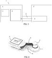
Figure 4 shows a monitoring system according to another embodiment of the invention. - The
monitoring system 1 will now be explained with reference toFigure 2 and3 .Figure 2 shows the monitoring system for monitoring acoustic heart signals according to one embodiment, andFigure 3 illustrates a block diagram of themonitoring system 1. Themonitoring system 1 comprises asensor housing 2 comprising a heartsound sensing element 3 adapted to be arranged in connection to a patient's heart to sense heart sound data and to generate a heart sound signal related to the heart sound data. The recordings by the heartsound sensing element 3 are preferably in the frequency field of 1-2000 Hz. Themonitoring system 1 also comprises amonitoring unit housing 4 comprising aprocessing unit 5 adapted to receive the heart sound signal, wherein themonitoring unit housing 4 is separated from thesensor housing 2. Theprocessing unit 5 is according to one embodiment accommodated in a monitoring unit (not shown). The monitoring unit is then accommodated in themonitoring unit housing 4 and further comprising at least one AD-converter to convert analogue recorded signals into digital signals, memory means and preferably a power supply such as a battery or power connection facilities to run the data management. Themonitoring unit housing 4 is further adapted to be arranged in relation to the patient's upper sternum. Themonitoring unit housing 4 may have adisplay 11 for display of data and/or a wireless communication solution for further transfer of analog or digital signals to an external unit. The external unit may e.g. be a smartphone or a computer. The digital signals are according to one embodiment processed by algorithms to make a read out value at the display showing a condition of the patient. InFigure 2 an ON/OFF button is shown, denoted 9. - The
monitoring system 1 further comprises a flexibleelongated connector 6 connecting thesensor housing 2 to themonitoring unit housing 4. Theconnector 6 has a longitudinal extension along alongitudinal axis 7. Theconnector 6 is connected to themonitoring unit housing 4 in an angular relationship, and wherein the angle α between thelongitudinal axis 7 and amain axis 8 of themonitoring unit housing 4 is within a predetermined interval. According to one embodiment the predetermined interval is 20-90 degrees. Themain axis 8 is an axis of themonitoring housing 4 intended to be located directly over and essentially parallel with the longitudinal extension of the breastbone of a patient when themonitoring system 1 is in use and correctly placed on a patient's chest. In the figures themonitoring unit housing 4 has a rectangular shape, and themain axis 8 is in this embodiment a centrally placed axis along the longitudinal extension of themonitoring unit housing 4. If themonitoring unit housing 4 has another shape, for example a circular shape, themonitoring unit housing 4 will in this context still have amain axis 8 which when themonitoring system 1 is in use and correctly placed, is located directly over and essentially parallel with the longitudinal extension of the breastbone of the patient. Themain axis 8 is according to one embodiment denoted on themonitoring housing 4 to guide a user to a correct placement of themonitoring housing 4. - The
connector 6 is preferably soft and resilient. Theconnector 6 is according to one embodiment characterized by connecting themonitoring unit housing 4 and thesensor housing 2 in a predetermined angle α and due to its flexible properties still allowing the positioning of themonitoring unit housing 4 and thesensor housing 2 in positions with other angles than the predetermined angle α without introducing disturbing and noise creating stresses between themonitoring unit housing 4 and thesensor housing 2. - The
connector 6 is preferably easy to bend in all directions and/or to twist up to +/- 45 degrees to facilitate a correct placement. To maintain the shape, theconnector 6 is according to one embodiment adapted to be resiliently twisted and/or bent. Thus, theconnector 6 will then return to its original shape after the recording or deformation. Theconnector 6 has according to one embodiment limited stretchability, to avoid major change of the distance between thehousings connector 6 is according to one embodiment dimensionally stable and displays shape integrity, thus the connector will essentially keep its shape. According to one embodiment, the flexibleelongated connector 6 is adapted to connect thehousings housings - The longitudinal extension of the flexible
elongated connector 6 is according to one embodiment between 10-100 mm, more preferably 25-50 mm. This length of theconnector 6 is preferred as it enables a placement of the monitoring system in which good recordings of heart sounds can be achieved. The longitudinal extension of the flexibleelongated connector 6 depends according to one embodiment on the chosen angle α between themonitoring unit housing 4 and thesensor housing 2. The flexibleelongated connector 6 has according to one embodiment a width d of 5-50 mm, more preferably 5-20 mm. The width d of theconnector 6 is shown inFigure 2 as a distance perpendicular to thelongitudinal axis 7 of theconnector 6. The required flexibility of theconnector 6 between themonitoring unit housing 4 and thesensor housing 2 is achieved by proper choice of dimensions and materials. For example, aconnector 6 with very soft and flexible material may require larger dimensions than aconnector 6 with more stiff and inflexible materials, to achieve the same stability. Preferred materials will have a low torsion modulus and have some degree of elasticity. Various types of elastomers and rubbers may be appropriate like materials having a shore A hardness preferably below 70, especially when construction thickness is more than 10-20 mm in the connection. However, preferred hardness will be shore A's below 50 and even more preferred below 40, and still even more preferred below 30. Kraton TR 1602 and TR 1101, Object Tango Black™ andKraiburg TF 4 FMS are specific examples of suitable elastomers of the invention. - The flexibility of the
connector 6 is according to one embodiment characterized by the ability to easy torsion. In clinical practice the required torsion for obtaining optimal sound recordings will be low and in general considerably lower than 45 degrees. As illustrated in example 1 below, the torque for a clinically common twisting of 15 degrees of theconnector 6 in a preferred embodiment will be around 0.002 Nm. With twisting torques above 0.04 Nm at torsions of 15 degrees acting on theconnector 6, theconnector 6 will be too stiff to serve the purpose of applying low twisting force to thesensor housing 2 when recording the sound of the heart. Preferred embodiments of theconnector 6 should thus need below 0.01 Nm in torque for twisting theconnector 6 about 15 degrees. - The force of torsion for a preferred embodiment of the
connector 6 connecting thesensor housing 2 with themonitoring unit housing 4 is described below: - The torsion is the twisting of the given object due to an applied torque measured in Nm. The torque of the
connector 6 with a length of 40 mm in a preferred embodiment was determined with the equipment "Tornado bottle tester, JKM Systems" manufactured by Mecmesin. The torque is depending on angular torsion and the determinations from torsions of 15 to 90 degrees are shown in the Table 1 below.Table 1 Degree Force/ Nm 15 0.002 30 0.005 45 0.009 90 0.030 - To transfer signals between the parts of the
monitoring system 1, theconnector 6 comprises according to one embodiment electrical means such as leads adapted to transfer electrical signals between thesensor housing 2 and themonitoring unit housing 4. Electrical connection may also or instead be achieved with a narrow flex print circuit board with printed leads, thus an interface for transferring of a plurality of electrical signals. - According to one embodiment shown in
Figure 4 , the monitoring system comprises anadhesive patch 10 adapted to attach thesensor housing 2 andmonitoring unit housing 4 to the skin of a patient. Theadhesive patch 10 for the monitoring system preferably has the same angle α as between thesensor housing 2 andmonitoring unit housing 4 between the intended position for thesensor housing 2 and the intended position for themonitoring unit housing 4. Thepatch 10 is preferably constructed from materials with high elasticity and flexibility characterized by allowing strain and twists with extremely low forces. According to one embodiment, theadhesive patch 10 comprises slits to allow non-stress movements and stretching. The construction is then cut with slits in the part which corresponds to theconnector 6, to allow movement and stretching of thepatch 10 without stress. Thus, when theconnector 6 is twisted or bent, thepatch 10 is designed such that it can follow the movement of theconnector 6. Thus, attachment of themonitoring system 1 to the skin of the patient can be achieved, and still allow for flexible movement of themonitoring system 1. Thepatch 10 will thus not prevent movement of the monitoring system. - The present invention is not limited to the above-described preferred embodiments. Various alternatives, modifications and equivalents may be used. Therefore, the above embodiments should not be taken as limiting the scope of the invention, which is defined by the appending claims.
Claims (10)
- Monitoring system (1) for monitoring acoustic heart signals, comprising
a sensor housing (2) comprising a heart sound sensing element (3) adapted to be arranged in connection to a patient's heart to sense heart sounds and to generate a heart sound signal related to the heart sounds;
a monitoring unit housing (4) comprising a processing unit (5) adapted to receive said heart sound signal, wherein said monitoring unit housing (4) is separated from said sensor housing (2) and is adapted to be arranged in relation to the patient's upper sternum
wherein said system (1) further comprises a flexible elongated connector (6) connecting said sensor housing (2) to said monitoring unit housing (4), said connector (6) having a longitudinal extension along a longitudinal axis (7), wherein said connector (6) is connected to said monitoring unit housing (4) in an angular relationship, the angle a between said longitudinal axis (7) and a main axis (8) of said monitoring unit housing (4) is within a predetermined interval, and characterized in that said flexible elongated connector (6) is adapted to be resiliently twisted and/or bent. - System according to claim 1, wherein said predetermined interval is 20-90 degrees.
- System according to claim 1 or 2, wherein said longitudinal extension is between 10-100 mm.
- System according to any of the preceding claims, wherein said flexible elongated connector (6) has a width of 5-50 mm.
- System according to any of the preceding claims 1 to 4, wherein said flexible elongated connector (6) comprises a material having a shore A hardness below 70, more preferred below 50 and even more preferably below 40.
- System according to any of the preceding claims, wherein said flexible elongated connector (6) is dimensionally stable and displays shape integrity.
- System according to any of the preceding claims, wherein said flexible elongated connector (6) comprises electrical means adapted to transfer electrical signals between said sensor housing (2) and said monitoring unit housing (4).
- System according to any of the preceding claims, wherein said flexible elongated connector (6) is adapted to connect said housings (2, 4) in a stable, semi-rigid but still flexible manner, such that said housings (2, 4) are constantly separated by said longitudinal extension.
- System according to any of the preceding claims, comprising an adhesive patch (10) adapted to attach said sensor housing (2) and monitoring unit housing (4) housing to the skin of a patient.
- System according to claim 10, wherein said adhesive patch (10) comprises slits to allow non-stress movements and stretching.
Applications Claiming Priority (3)
| Application Number | Priority Date | Filing Date | Title |
|---|---|---|---|
| US201261660883P | 2012-06-18 | 2012-06-18 | |
| SE1250640 | 2012-06-18 | ||
| PCT/EP2013/062467 WO2013189866A1 (en) | 2012-06-18 | 2013-06-17 | A monitoring system for monitoring of heart signals |
Publications (2)
| Publication Number | Publication Date |
|---|---|
| EP2861150A1 EP2861150A1 (en) | 2015-04-22 |
| EP2861150B1 true EP2861150B1 (en) | 2016-12-07 |
Family
ID=49768157
Family Applications (1)
| Application Number | Title | Priority Date | Filing Date |
|---|---|---|---|
| EP13732394.5A Active EP2861150B1 (en) | 2012-06-18 | 2013-06-17 | A monitoring system for monitoring of heart signals |
Country Status (8)
| Country | Link |
|---|---|
| US (1) | US9610059B2 (en) |
| EP (1) | EP2861150B1 (en) |
| JP (1) | JP6231086B2 (en) |
| CN (1) | CN104507393B (en) |
| BR (1) | BR112014031527A2 (en) |
| IN (1) | IN2014DN09873A (en) |
| RU (1) | RU2014152458A (en) |
| WO (1) | WO2013189866A1 (en) |
Families Citing this family (3)
| Publication number | Priority date | Publication date | Assignee | Title |
|---|---|---|---|---|
| US9497558B1 (en) * | 2014-06-27 | 2016-11-15 | Andrew Robert Millikin | Bodily function sound anonymization |
| US11717253B2 (en) * | 2019-11-22 | 2023-08-08 | Richard D. Jones | Systems and methods for recording and/or monitoring heart activity |
| WO2022123397A1 (en) * | 2020-12-11 | 2022-06-16 | 3M Innovative Properties Company | Wireless auscultation device and connector |
Family Cites Families (24)
| Publication number | Priority date | Publication date | Assignee | Title |
|---|---|---|---|---|
| US4878501A (en) * | 1986-09-24 | 1989-11-07 | Shue Ming Jeng | Electronic stethoscopic apparatus |
| JPH079506Y2 (en) * | 1986-11-26 | 1995-03-06 | ソニー株式会社 | Microphone |
| JPS63146604U (en) * | 1987-03-16 | 1988-09-27 | ||
| US5078134A (en) * | 1988-04-25 | 1992-01-07 | Lifecor, Inc. | Portable device for sensing cardiac function and automatically delivering electrical therapy |
| JP2631261B2 (en) * | 1993-02-23 | 1997-07-16 | 務 大竹 | Bioelectric signal recorder |
| KR960034657A (en) * | 1995-03-28 | 1996-10-24 | 한승준 | Door checker mounting structure of vehicle |
| US6117077A (en) * | 1999-01-22 | 2000-09-12 | Del Mar Medical Systems, Llc | Long-term, ambulatory physiological recorder |
| EP1217942A1 (en) * | 1999-09-24 | 2002-07-03 | Healthetech, Inc. | Physiological monitor and associated computation, display and communication unit |
| JP2003521972A (en) * | 1999-09-24 | 2003-07-22 | ヘルセテック インコーポレイテッド | Physiological monitoring device and associated calculation, display and communication device |
| JP2001156897A (en) * | 1999-11-30 | 2001-06-08 | Fujitsu Ltd | Portable communication apparatus |
| US7096060B2 (en) * | 2003-06-27 | 2006-08-22 | Innovise Medical, Inc. | Method and system for detection of heart sounds |
| US20060030781A1 (en) * | 2004-08-05 | 2006-02-09 | Adnan Shennib | Emergency heart sensor patch |
| GB2438324A (en) * | 2005-02-25 | 2007-11-21 | Byung Hoon Lee | Mobile phone with a stethoscope |
| KR200389343Y1 (en) | 2005-02-25 | 2005-07-14 | 이병훈 | Cellular Phone with Stethoscope |
| EP2266661B1 (en) * | 2005-03-25 | 2016-08-10 | Zoll Medical Corporation | Integrated resuscitation |
| US20070041273A1 (en) * | 2005-06-21 | 2007-02-22 | Shertukde Hemchandra M | Acoustic sensor |
| US9398891B2 (en) * | 2005-10-20 | 2016-07-26 | Tiba Medical, Inc. | Multiple communication interface medical examination apparatus, system, and/or method |
| US20080228095A1 (en) * | 2007-03-15 | 2008-09-18 | Richardson Mary | Medical device |
| US8038629B2 (en) | 2007-10-02 | 2011-10-18 | Board Of Regents, The University Of Texas System | Digital endotracheal tube sound acquisition and localization device |
| WO2009080040A1 (en) | 2007-12-20 | 2009-07-02 | Coloplast A/S | An adhesive patch for monitoring acoustic signals |
| US8771204B2 (en) | 2008-12-30 | 2014-07-08 | Masimo Corporation | Acoustic sensor assembly |
| US9357929B2 (en) * | 2010-07-27 | 2016-06-07 | Carefusion 303, Inc. | System and method for monitoring body temperature of a person |
| CN102685285B (en) | 2011-03-18 | 2016-08-24 | 上海华勤通讯技术有限公司 | There is the mobile phone of stethoscope function |
| US9615790B2 (en) * | 2011-07-14 | 2017-04-11 | Verathon Inc. | Sensor device with flexible joints |
-
2013
- 2013-06-17 EP EP13732394.5A patent/EP2861150B1/en active Active
- 2013-06-17 RU RU2014152458A patent/RU2014152458A/en not_active Application Discontinuation
- 2013-06-17 US US14/408,953 patent/US9610059B2/en active Active
- 2013-06-17 BR BR112014031527A patent/BR112014031527A2/en not_active Application Discontinuation
- 2013-06-17 JP JP2015516644A patent/JP6231086B2/en active Active
- 2013-06-17 CN CN201380031699.1A patent/CN104507393B/en active Active
- 2013-06-17 WO PCT/EP2013/062467 patent/WO2013189866A1/en active Application Filing
- 2013-06-17 IN IN9873DEN2014 patent/IN2014DN09873A/en unknown
Also Published As
| Publication number | Publication date |
|---|---|
| RU2014152458A (en) | 2016-08-10 |
| EP2861150A1 (en) | 2015-04-22 |
| JP6231086B2 (en) | 2017-11-15 |
| JP2015524679A (en) | 2015-08-27 |
| CN104507393B (en) | 2017-05-10 |
| US20150190109A1 (en) | 2015-07-09 |
| IN2014DN09873A (en) | 2015-08-07 |
| WO2013189866A1 (en) | 2013-12-27 |
| BR112014031527A2 (en) | 2017-06-27 |
| CN104507393A (en) | 2015-04-08 |
| US9610059B2 (en) | 2017-04-04 |
Similar Documents
| Publication | Publication Date | Title |
|---|---|---|
| JP6588897B2 (en) | Patch, readout device, system and method for detecting abdominal electrophysiological signals | |
| KR101902594B1 (en) | Wireless fetal monitoring system | |
| US20190365263A1 (en) | Digital stethoscope using mechano-acoustic sensor suite | |
| KR101861612B1 (en) | Connector Interface System for Data Acquisition | |
| EP2783627A1 (en) | Diagnostic device | |
| US10349853B2 (en) | Medical electrode | |
| KR101674579B1 (en) | Electrode for living body and device for detecting living signal | |
| US10881313B2 (en) | Emergency cardiac and electrocardiogram electrode placement system | |
| US6878117B1 (en) | Handheld sensor for acoustic data acquisition | |
| JP2012055354A (en) | Diagnostic device | |
| US20020038089A1 (en) | Handheld sensor for acoustic data acquisition | |
| EP2861150B1 (en) | A monitoring system for monitoring of heart signals | |
| US11950913B2 (en) | Electrocardiogram sensor | |
| CN107530008B (en) | Sensor unit | |
| JP2010259679A (en) | Electrocardiogram waveform measuring sensor | |
| US9289149B2 (en) | Apparatus and method for wirelessly transferring and storing medical data | |
| JP2004249107A (en) | Patient monitoring system | |
| US20160206224A1 (en) | Ecg electrode snap connector and associated methods | |
| CN113710165A (en) | Ultrasound device including removable acoustic coupling pad | |
| US20090326418A1 (en) | Microphone matrix for recording body sounds | |
| US20120226126A1 (en) | Method and Apparatus for Acquiring Data Relating to a Physiological Condition of a Subject When Chest Wall Access is Limited | |
| WO2001022884A1 (en) | Handheld sensor for acoustic data acquisition | |
| WO2001017432A1 (en) | Improvements in or relating to ultrasound devices |
Legal Events
| Date | Code | Title | Description |
|---|---|---|---|
| PUAI | Public reference made under article 153(3) epc to a published international application that has entered the european phase |
Free format text: ORIGINAL CODE: 0009012 |
|
| 17P | Request for examination filed |
Effective date: 20150107 |
|
| AK | Designated contracting states |
Kind code of ref document: A1 Designated state(s): AL AT BE BG CH CY CZ DE DK EE ES FI FR GB GR HR HU IE IS IT LI LT LU LV MC MK MT NL NO PL PT RO RS SE SI SK SM TR |
|
| AX | Request for extension of the european patent |
Extension state: BA ME |
|
| DAX | Request for extension of the european patent (deleted) | ||
| REG | Reference to a national code |
Ref country code: DE Ref legal event code: R079 Ref document number: 602013015025 Country of ref document: DE Free format text: PREVIOUS MAIN CLASS: A61B0007040000 Ipc: A61B0005020000 |
|
| GRAP | Despatch of communication of intention to grant a patent |
Free format text: ORIGINAL CODE: EPIDOSNIGR1 |
|
| RIC1 | Information provided on ipc code assigned before grant |
Ipc: A61B 5/024 20060101ALI20160613BHEP Ipc: A61B 5/02 20060101AFI20160613BHEP Ipc: A61B 7/04 20060101ALI20160613BHEP Ipc: A61B 5/0404 20060101ALI20160613BHEP Ipc: A61B 5/00 20060101ALI20160613BHEP |
|
| INTG | Intention to grant announced |
Effective date: 20160630 |
|
| GRAS | Grant fee paid |
Free format text: ORIGINAL CODE: EPIDOSNIGR3 |
|
| STAA | Information on the status of an ep patent application or granted ep patent |
Free format text: STATUS: GRANT OF PATENT IS INTENDED |
|
| GRAA | (expected) grant |
Free format text: ORIGINAL CODE: 0009210 |
|
| STAA | Information on the status of an ep patent application or granted ep patent |
Free format text: STATUS: THE PATENT HAS BEEN GRANTED |
|
| AK | Designated contracting states |
Kind code of ref document: B1 Designated state(s): AL AT BE BG CH CY CZ DE DK EE ES FI FR GB GR HR HU IE IS IT LI LT LU LV MC MK MT NL NO PL PT RO RS SE SI SK SM TR |
|
| REG | Reference to a national code |
Ref country code: GB Ref legal event code: FG4D |
|
| REG | Reference to a national code |
Ref country code: CH Ref legal event code: EP Ref country code: AT Ref legal event code: REF Ref document number: 851000 Country of ref document: AT Kind code of ref document: T Effective date: 20161215 |
|
| REG | Reference to a national code |
Ref country code: IE Ref legal event code: FG4D |
|
| REG | Reference to a national code |
Ref country code: DE Ref legal event code: R096 Ref document number: 602013015025 Country of ref document: DE |
|
| RAP2 | Party data changed (patent owner data changed or rights of a patent transferred) |
Owner name: ACARIX A/S |
|
| PG25 | Lapsed in a contracting state [announced via postgrant information from national office to epo] |
Ref country code: LV Free format text: LAPSE BECAUSE OF FAILURE TO SUBMIT A TRANSLATION OF THE DESCRIPTION OR TO PAY THE FEE WITHIN THE PRESCRIBED TIME-LIMIT Effective date: 20161207 |
|
| REG | Reference to a national code |
Ref country code: LT Ref legal event code: MG4D |
|
| REG | Reference to a national code |
Ref country code: NL Ref legal event code: MP Effective date: 20161207 |
|
| PG25 | Lapsed in a contracting state [announced via postgrant information from national office to epo] |
Ref country code: GR Free format text: LAPSE BECAUSE OF FAILURE TO SUBMIT A TRANSLATION OF THE DESCRIPTION OR TO PAY THE FEE WITHIN THE PRESCRIBED TIME-LIMIT Effective date: 20170308 Ref country code: NO Free format text: LAPSE BECAUSE OF FAILURE TO SUBMIT A TRANSLATION OF THE DESCRIPTION OR TO PAY THE FEE WITHIN THE PRESCRIBED TIME-LIMIT Effective date: 20170307 Ref country code: LT Free format text: LAPSE BECAUSE OF FAILURE TO SUBMIT A TRANSLATION OF THE DESCRIPTION OR TO PAY THE FEE WITHIN THE PRESCRIBED TIME-LIMIT Effective date: 20161207 Ref country code: SE Free format text: LAPSE BECAUSE OF FAILURE TO SUBMIT A TRANSLATION OF THE DESCRIPTION OR TO PAY THE FEE WITHIN THE PRESCRIBED TIME-LIMIT Effective date: 20161207 |
|
| REG | Reference to a national code |
Ref country code: AT Ref legal event code: MK05 Ref document number: 851000 Country of ref document: AT Kind code of ref document: T Effective date: 20161207 |
|
| PG25 | Lapsed in a contracting state [announced via postgrant information from national office to epo] |
Ref country code: ES Free format text: LAPSE BECAUSE OF FAILURE TO SUBMIT A TRANSLATION OF THE DESCRIPTION OR TO PAY THE FEE WITHIN THE PRESCRIBED TIME-LIMIT Effective date: 20161207 Ref country code: HR Free format text: LAPSE BECAUSE OF FAILURE TO SUBMIT A TRANSLATION OF THE DESCRIPTION OR TO PAY THE FEE WITHIN THE PRESCRIBED TIME-LIMIT Effective date: 20161207 Ref country code: RS Free format text: LAPSE BECAUSE OF FAILURE TO SUBMIT A TRANSLATION OF THE DESCRIPTION OR TO PAY THE FEE WITHIN THE PRESCRIBED TIME-LIMIT Effective date: 20161207 Ref country code: FI Free format text: LAPSE BECAUSE OF FAILURE TO SUBMIT A TRANSLATION OF THE DESCRIPTION OR TO PAY THE FEE WITHIN THE PRESCRIBED TIME-LIMIT Effective date: 20161207 |
|
| REG | Reference to a national code |
Ref country code: FR Ref legal event code: PLFP Year of fee payment: 5 |
|
| PG25 | Lapsed in a contracting state [announced via postgrant information from national office to epo] |
Ref country code: NL Free format text: LAPSE BECAUSE OF FAILURE TO SUBMIT A TRANSLATION OF THE DESCRIPTION OR TO PAY THE FEE WITHIN THE PRESCRIBED TIME-LIMIT Effective date: 20161207 |
|
| PG25 | Lapsed in a contracting state [announced via postgrant information from national office to epo] |
Ref country code: SK Free format text: LAPSE BECAUSE OF FAILURE TO SUBMIT A TRANSLATION OF THE DESCRIPTION OR TO PAY THE FEE WITHIN THE PRESCRIBED TIME-LIMIT Effective date: 20161207 Ref country code: RO Free format text: LAPSE BECAUSE OF FAILURE TO SUBMIT A TRANSLATION OF THE DESCRIPTION OR TO PAY THE FEE WITHIN THE PRESCRIBED TIME-LIMIT Effective date: 20161207 Ref country code: CZ Free format text: LAPSE BECAUSE OF FAILURE TO SUBMIT A TRANSLATION OF THE DESCRIPTION OR TO PAY THE FEE WITHIN THE PRESCRIBED TIME-LIMIT Effective date: 20161207 Ref country code: IS Free format text: LAPSE BECAUSE OF FAILURE TO SUBMIT A TRANSLATION OF THE DESCRIPTION OR TO PAY THE FEE WITHIN THE PRESCRIBED TIME-LIMIT Effective date: 20170407 Ref country code: EE Free format text: LAPSE BECAUSE OF FAILURE TO SUBMIT A TRANSLATION OF THE DESCRIPTION OR TO PAY THE FEE WITHIN THE PRESCRIBED TIME-LIMIT Effective date: 20161207 |
|
| PG25 | Lapsed in a contracting state [announced via postgrant information from national office to epo] |
Ref country code: IT Free format text: LAPSE BECAUSE OF FAILURE TO SUBMIT A TRANSLATION OF THE DESCRIPTION OR TO PAY THE FEE WITHIN THE PRESCRIBED TIME-LIMIT Effective date: 20161207 Ref country code: PT Free format text: LAPSE BECAUSE OF FAILURE TO SUBMIT A TRANSLATION OF THE DESCRIPTION OR TO PAY THE FEE WITHIN THE PRESCRIBED TIME-LIMIT Effective date: 20170407 Ref country code: PL Free format text: LAPSE BECAUSE OF FAILURE TO SUBMIT A TRANSLATION OF THE DESCRIPTION OR TO PAY THE FEE WITHIN THE PRESCRIBED TIME-LIMIT Effective date: 20161207 Ref country code: AT Free format text: LAPSE BECAUSE OF FAILURE TO SUBMIT A TRANSLATION OF THE DESCRIPTION OR TO PAY THE FEE WITHIN THE PRESCRIBED TIME-LIMIT Effective date: 20161207 Ref country code: SM Free format text: LAPSE BECAUSE OF FAILURE TO SUBMIT A TRANSLATION OF THE DESCRIPTION OR TO PAY THE FEE WITHIN THE PRESCRIBED TIME-LIMIT Effective date: 20161207 Ref country code: BG Free format text: LAPSE BECAUSE OF FAILURE TO SUBMIT A TRANSLATION OF THE DESCRIPTION OR TO PAY THE FEE WITHIN THE PRESCRIBED TIME-LIMIT Effective date: 20170307 Ref country code: BE Free format text: LAPSE BECAUSE OF FAILURE TO SUBMIT A TRANSLATION OF THE DESCRIPTION OR TO PAY THE FEE WITHIN THE PRESCRIBED TIME-LIMIT Effective date: 20161207 |
|
| REG | Reference to a national code |
Ref country code: DE Ref legal event code: R097 Ref document number: 602013015025 Country of ref document: DE |
|
| PLBE | No opposition filed within time limit |
Free format text: ORIGINAL CODE: 0009261 |
|
| STAA | Information on the status of an ep patent application or granted ep patent |
Free format text: STATUS: NO OPPOSITION FILED WITHIN TIME LIMIT |
|
| 26N | No opposition filed |
Effective date: 20170908 |
|
| PG25 | Lapsed in a contracting state [announced via postgrant information from national office to epo] |
Ref country code: DK Free format text: LAPSE BECAUSE OF FAILURE TO SUBMIT A TRANSLATION OF THE DESCRIPTION OR TO PAY THE FEE WITHIN THE PRESCRIBED TIME-LIMIT Effective date: 20161207 Ref country code: SI Free format text: LAPSE BECAUSE OF FAILURE TO SUBMIT A TRANSLATION OF THE DESCRIPTION OR TO PAY THE FEE WITHIN THE PRESCRIBED TIME-LIMIT Effective date: 20161207 |
|
| PG25 | Lapsed in a contracting state [announced via postgrant information from national office to epo] |
Ref country code: MC Free format text: LAPSE BECAUSE OF FAILURE TO SUBMIT A TRANSLATION OF THE DESCRIPTION OR TO PAY THE FEE WITHIN THE PRESCRIBED TIME-LIMIT Effective date: 20161207 |
|
| REG | Reference to a national code |
Ref country code: CH Ref legal event code: PL |
|
| REG | Reference to a national code |
Ref country code: IE Ref legal event code: MM4A |
|
| PG25 | Lapsed in a contracting state [announced via postgrant information from national office to epo] |
Ref country code: IE Free format text: LAPSE BECAUSE OF NON-PAYMENT OF DUE FEES Effective date: 20170617 Ref country code: LU Free format text: LAPSE BECAUSE OF NON-PAYMENT OF DUE FEES Effective date: 20170617 Ref country code: LI Free format text: LAPSE BECAUSE OF NON-PAYMENT OF DUE FEES Effective date: 20170630 Ref country code: CH Free format text: LAPSE BECAUSE OF NON-PAYMENT OF DUE FEES Effective date: 20170630 |
|
| REG | Reference to a national code |
Ref country code: FR Ref legal event code: PLFP Year of fee payment: 6 |
|
| PG25 | Lapsed in a contracting state [announced via postgrant information from national office to epo] |
Ref country code: MT Free format text: LAPSE BECAUSE OF NON-PAYMENT OF DUE FEES Effective date: 20170617 |
|
| PG25 | Lapsed in a contracting state [announced via postgrant information from national office to epo] |
Ref country code: HU Free format text: LAPSE BECAUSE OF FAILURE TO SUBMIT A TRANSLATION OF THE DESCRIPTION OR TO PAY THE FEE WITHIN THE PRESCRIBED TIME-LIMIT; INVALID AB INITIO Effective date: 20130617 |
|
| PG25 | Lapsed in a contracting state [announced via postgrant information from national office to epo] |
Ref country code: CY Free format text: LAPSE BECAUSE OF FAILURE TO SUBMIT A TRANSLATION OF THE DESCRIPTION OR TO PAY THE FEE WITHIN THE PRESCRIBED TIME-LIMIT Effective date: 20161207 |
|
| PG25 | Lapsed in a contracting state [announced via postgrant information from national office to epo] |
Ref country code: MK Free format text: LAPSE BECAUSE OF FAILURE TO SUBMIT A TRANSLATION OF THE DESCRIPTION OR TO PAY THE FEE WITHIN THE PRESCRIBED TIME-LIMIT Effective date: 20161207 |
|
| PG25 | Lapsed in a contracting state [announced via postgrant information from national office to epo] |
Ref country code: TR Free format text: LAPSE BECAUSE OF FAILURE TO SUBMIT A TRANSLATION OF THE DESCRIPTION OR TO PAY THE FEE WITHIN THE PRESCRIBED TIME-LIMIT Effective date: 20161207 |
|
| PG25 | Lapsed in a contracting state [announced via postgrant information from national office to epo] |
Ref country code: AL Free format text: LAPSE BECAUSE OF FAILURE TO SUBMIT A TRANSLATION OF THE DESCRIPTION OR TO PAY THE FEE WITHIN THE PRESCRIBED TIME-LIMIT Effective date: 20161207 |
|
| PGFP | Annual fee paid to national office [announced via postgrant information from national office to epo] |
Ref country code: FR Payment date: 20230619 Year of fee payment: 11 Ref country code: DE Payment date: 20230621 Year of fee payment: 11 |
|
| PGFP | Annual fee paid to national office [announced via postgrant information from national office to epo] |
Ref country code: GB Payment date: 20230619 Year of fee payment: 11 |