JP6587975B2 - Support structure for rotating member - Google Patents
Support structure for rotating member Download PDFInfo
- Publication number
- JP6587975B2 JP6587975B2 JP2016098173A JP2016098173A JP6587975B2 JP 6587975 B2 JP6587975 B2 JP 6587975B2 JP 2016098173 A JP2016098173 A JP 2016098173A JP 2016098173 A JP2016098173 A JP 2016098173A JP 6587975 B2 JP6587975 B2 JP 6587975B2
- Authority
- JP
- Japan
- Prior art keywords
- rotating member
- support
- support surface
- thrust washer
- cross
- Prior art date
- Legal status (The legal status is an assumption and is not a legal conclusion. Google has not performed a legal analysis and makes no representation as to the accuracy of the status listed.)
- Active
Links
- 230000002093 peripheral effect Effects 0.000 description 23
- 230000005540 biological transmission Effects 0.000 description 16
- 239000010687 lubricating oil Substances 0.000 description 12
- 230000001050 lubricating effect Effects 0.000 description 7
- 230000000694 effects Effects 0.000 description 5
- 230000007246 mechanism Effects 0.000 description 4
- 239000003921 oil Substances 0.000 description 4
- 230000006872 improvement Effects 0.000 description 2
- 238000005461 lubrication Methods 0.000 description 2
- 230000000717 retained effect Effects 0.000 description 2
- 238000003466 welding Methods 0.000 description 2
- 230000008859 change Effects 0.000 description 1
- 230000008878 coupling Effects 0.000 description 1
- 238000010168 coupling process Methods 0.000 description 1
- 238000005859 coupling reaction Methods 0.000 description 1
- 230000007423 decrease Effects 0.000 description 1
- 230000005489 elastic deformation Effects 0.000 description 1
- 230000002349 favourable effect Effects 0.000 description 1
- 230000000149 penetrating effect Effects 0.000 description 1
- 238000007789 sealing Methods 0.000 description 1
- 230000001629 suppression Effects 0.000 description 1
Images


Classifications
-
- F—MECHANICAL ENGINEERING; LIGHTING; HEATING; WEAPONS; BLASTING
- F16—ENGINEERING ELEMENTS AND UNITS; GENERAL MEASURES FOR PRODUCING AND MAINTAINING EFFECTIVE FUNCTIONING OF MACHINES OR INSTALLATIONS; THERMAL INSULATION IN GENERAL
- F16H—GEARING
- F16H48/00—Differential gearings
- F16H48/38—Constructional details
-
- F—MECHANICAL ENGINEERING; LIGHTING; HEATING; WEAPONS; BLASTING
- F16—ENGINEERING ELEMENTS AND UNITS; GENERAL MEASURES FOR PRODUCING AND MAINTAINING EFFECTIVE FUNCTIONING OF MACHINES OR INSTALLATIONS; THERMAL INSULATION IN GENERAL
- F16H—GEARING
- F16H48/00—Differential gearings
- F16H48/06—Differential gearings with gears having orbital motion
- F16H48/08—Differential gearings with gears having orbital motion comprising bevel gears
-
- F—MECHANICAL ENGINEERING; LIGHTING; HEATING; WEAPONS; BLASTING
- F16—ENGINEERING ELEMENTS AND UNITS; GENERAL MEASURES FOR PRODUCING AND MAINTAINING EFFECTIVE FUNCTIONING OF MACHINES OR INSTALLATIONS; THERMAL INSULATION IN GENERAL
- F16C—SHAFTS; FLEXIBLE SHAFTS; ELEMENTS OR CRANKSHAFT MECHANISMS; ROTARY BODIES OTHER THAN GEARING ELEMENTS; BEARINGS
- F16C17/00—Sliding-contact bearings for exclusively rotary movement
- F16C17/04—Sliding-contact bearings for exclusively rotary movement for axial load only
-
- F—MECHANICAL ENGINEERING; LIGHTING; HEATING; WEAPONS; BLASTING
- F16—ENGINEERING ELEMENTS AND UNITS; GENERAL MEASURES FOR PRODUCING AND MAINTAINING EFFECTIVE FUNCTIONING OF MACHINES OR INSTALLATIONS; THERMAL INSULATION IN GENERAL
- F16C—SHAFTS; FLEXIBLE SHAFTS; ELEMENTS OR CRANKSHAFT MECHANISMS; ROTARY BODIES OTHER THAN GEARING ELEMENTS; BEARINGS
- F16C23/00—Bearings for exclusively rotary movement adjustable for aligning or positioning
- F16C23/02—Sliding-contact bearings
- F16C23/04—Sliding-contact bearings self-adjusting
- F16C23/043—Sliding-contact bearings self-adjusting with spherical surfaces, e.g. spherical plain bearings
- F16C23/048—Sliding-contact bearings self-adjusting with spherical surfaces, e.g. spherical plain bearings for axial load mainly
-
- F—MECHANICAL ENGINEERING; LIGHTING; HEATING; WEAPONS; BLASTING
- F16—ENGINEERING ELEMENTS AND UNITS; GENERAL MEASURES FOR PRODUCING AND MAINTAINING EFFECTIVE FUNCTIONING OF MACHINES OR INSTALLATIONS; THERMAL INSULATION IN GENERAL
- F16C—SHAFTS; FLEXIBLE SHAFTS; ELEMENTS OR CRANKSHAFT MECHANISMS; ROTARY BODIES OTHER THAN GEARING ELEMENTS; BEARINGS
- F16C33/00—Parts of bearings; Special methods for making bearings or parts thereof
- F16C33/02—Parts of sliding-contact bearings
- F16C33/04—Brasses; Bushes; Linings
- F16C33/06—Sliding surface mainly made of metal
- F16C33/10—Construction relative to lubrication
- F16C33/1025—Construction relative to lubrication with liquid, e.g. oil, as lubricant
- F16C33/103—Construction relative to lubrication with liquid, e.g. oil, as lubricant retained in or near the bearing
-
- F—MECHANICAL ENGINEERING; LIGHTING; HEATING; WEAPONS; BLASTING
- F16—ENGINEERING ELEMENTS AND UNITS; GENERAL MEASURES FOR PRODUCING AND MAINTAINING EFFECTIVE FUNCTIONING OF MACHINES OR INSTALLATIONS; THERMAL INSULATION IN GENERAL
- F16H—GEARING
- F16H48/00—Differential gearings
- F16H48/38—Constructional details
- F16H48/40—Constructional details characterised by features of the rotating cases
-
- F—MECHANICAL ENGINEERING; LIGHTING; HEATING; WEAPONS; BLASTING
- F16—ENGINEERING ELEMENTS AND UNITS; GENERAL MEASURES FOR PRODUCING AND MAINTAINING EFFECTIVE FUNCTIONING OF MACHINES OR INSTALLATIONS; THERMAL INSULATION IN GENERAL
- F16H—GEARING
- F16H57/00—General details of gearing
- F16H57/04—Features relating to lubrication or cooling or heating
- F16H57/042—Guidance of lubricant
- F16H57/0421—Guidance of lubricant on or within the casing, e.g. shields or baffles for collecting lubricant, tubes, pipes, grooves, channels or the like
- F16H57/0424—Lubricant guiding means in the wall of or integrated with the casing, e.g. grooves, channels, holes
-
- F—MECHANICAL ENGINEERING; LIGHTING; HEATING; WEAPONS; BLASTING
- F16—ENGINEERING ELEMENTS AND UNITS; GENERAL MEASURES FOR PRODUCING AND MAINTAINING EFFECTIVE FUNCTIONING OF MACHINES OR INSTALLATIONS; THERMAL INSULATION IN GENERAL
- F16C—SHAFTS; FLEXIBLE SHAFTS; ELEMENTS OR CRANKSHAFT MECHANISMS; ROTARY BODIES OTHER THAN GEARING ELEMENTS; BEARINGS
- F16C2361/00—Apparatus or articles in engineering in general
- F16C2361/61—Toothed gear systems, e.g. support of pinion shafts
-
- F—MECHANICAL ENGINEERING; LIGHTING; HEATING; WEAPONS; BLASTING
- F16—ENGINEERING ELEMENTS AND UNITS; GENERAL MEASURES FOR PRODUCING AND MAINTAINING EFFECTIVE FUNCTIONING OF MACHINES OR INSTALLATIONS; THERMAL INSULATION IN GENERAL
- F16H—GEARING
- F16H48/00—Differential gearings
- F16H48/06—Differential gearings with gears having orbital motion
- F16H48/08—Differential gearings with gears having orbital motion comprising bevel gears
- F16H2048/087—Differential gearings with gears having orbital motion comprising bevel gears characterised by the pinion gears, e.g. their type or arrangement
Landscapes
- Engineering & Computer Science (AREA)
- General Engineering & Computer Science (AREA)
- Mechanical Engineering (AREA)
- Chemical & Material Sciences (AREA)
- Oil, Petroleum & Natural Gas (AREA)
- Retarders (AREA)
- General Details Of Gearings (AREA)
- Sliding-Contact Bearings (AREA)
Description
本発明は、支持体の支持面に回転部材の背面が回転摺動可能に支持される、回転部材の支持構造に関する。 The present invention relates to a rotating member support structure in which a back surface of a rotating member is supported on a supporting surface of a support body so as to be able to rotate and slide.
上記支持構造として、支持体(例えばデフケース)の凹状球面よりなる支持面に、回転部材(例えばベベルギヤ)の凸状球面よりなる背面を摺接可能に対面させるようにしたものは、差動装置等の機械装置において従来より知られている。 As the above-described support structure, a support device (for example, a differential case) having a concave spherical surface is configured such that a back surface formed by a convex spherical surface of a rotating member (for example, bevel gear) is slidably contacted, such as a differential device In the conventional mechanical device, it is known.
そして、この従来の構造では、支持体の支持面と、回転部材の背面とが同じ曲率半径の球面状に形成されていたので、両者の接触面間には、潤滑油の保持空間となる隙間を十分には確保し得ない問題があった。 In this conventional structure, since the support surface of the support and the back surface of the rotating member are formed in a spherical shape having the same radius of curvature, a gap serving as a lubricating oil holding space is formed between the contact surfaces of the both. There was a problem that could not be secured sufficiently.
ところで上記問題を解決するために、曲率半径が互いに同一であるデフケース(支持体)の支持面とピニオンギヤ(回転部材)の背面との間に、上記曲率半径よりも大きい曲率半径で球面状に湾曲した板状のスラストワッシャを介装させたものが特許文献1により開示されている。そして、特許文献1には、スラストワッシャの外側面とデフケースの支持面との間、並びにスラストワッシャの内側面とピニオンギヤの背面との間にそれぞれ適度な隙間(即ち油保持空間)が確保されて、デフケース等の摩耗抑制が図られることが記載されている。 By the way, in order to solve the above problem, a curved surface having a radius of curvature larger than the radius of curvature is curved between the support surface of the differential case (support) having the same radius of curvature and the back surface of the pinion gear (rotating member). Japanese Patent Application Laid-Open No. H10-228667 discloses a plate-like thrust washer interposed. In Patent Document 1, appropriate gaps (that is, oil holding spaces) are secured between the outer surface of the thrust washer and the support surface of the differential case, and between the inner surface of the thrust washer and the back surface of the pinion gear. Further, it is described that wear of a differential case or the like can be suppressed.
しかしながら特許文献1のものでは、スラストワッシャが大きなスラスト荷重を受けて弾性変形した場合に、スラストワッシャの外側面及び内側面がデフケースの支持面及びピニオンギヤの背面にそれぞれ全面に亘り密着することがある。この場合には、上記した隙間が無くなり、そこに潤滑油を十分に保持し得なくなって潤滑性が低下する。そのため、ピニオンギヤが回転時にデフケースより受ける回転摺動抵抗が増大して、伝動装置の伝動効率が低下する等の問題がある。 However, in Patent Document 1, when the thrust washer is elastically deformed by receiving a large thrust load, the outer surface and inner surface of the thrust washer may be in close contact with the support surface of the differential case and the back surface of the pinion gear, respectively. . In this case, the above-described gap disappears, and the lubricating oil cannot be sufficiently retained therein, so that the lubricity is lowered. Therefore, there is a problem that the rotational sliding resistance that the pinion gear receives from the differential case during rotation increases, and the transmission efficiency of the transmission device decreases.
本発明は、かかる事情に鑑みてなされたもので、簡単な構造で従来構造の上記問題を解決することができる、回転部材の支持構造を提供することを目的とする。 The present invention has been made in view of such circumstances, and an object of the present invention is to provide a support structure for a rotating member that can solve the above-described problems of the conventional structure with a simple structure.
上記目的を達成するために、本発明は、回転部材を所定軸線回りに回転自在に支持する支持体に、前記回転部材とは反対側に凹んだ球面状の支持面が設けられ、前記支持面に前記回転部材の背面が回転摺動可能に支持される、回転部材の支持構造において、前記回転部材の前記背面は、前記所定軸線を全部含む横断面で見て、前記所定軸線を挟んで両側部分が各々、前記支持面の側に膨らむように段差なく滑らかに彎曲した凸曲面を有しており、前記凸曲面の、前記横断面で見て両端より離れた頂部で前記背面が前記支持面に支持されるように、前記横断面で見て少なくとも前記頂部の曲率半径が前記支持面の曲率半径よりも小さく設定されていることを第1の特徴とする。 In order to achieve the above object, according to the present invention, a supporting body that rotatably supports a rotating member around a predetermined axis is provided with a spherical supporting surface that is recessed on the opposite side of the rotating member, and the supporting surface is provided. In the rotating member support structure, the back surface of the rotating member is supported so as to be slidable in rotation, and the back surface of the rotating member is on both sides of the predetermined axis as seen in a cross section including the predetermined axis. Each of the portions has a convex curved surface smoothly curved without a step so as to swell toward the supporting surface, and the back surface of the convex curved surface is separated from both ends when viewed in the cross section. The first feature is that at least the radius of curvature of the top portion is set to be smaller than the radius of curvature of the support surface as viewed in the cross section.
また本発明は、第1の特徴に加えて、前記頂部が、前記横断面で見て前記所定軸線の径方向で前記凸曲面の中点よりも前記所定軸線の側にオフセット配置されることを第2の特徴とする。 In addition to the first feature, the present invention is configured such that the top portion is offset from the midpoint of the convex curved surface in the radial direction of the predetermined axis when viewed in the cross section, closer to the predetermined axis. The second feature.
また本発明は、第1又は第2の特徴に加えて、前記支持面と前記背面との間には、外側面が前記支持面の側に凸の球面状であるスラストワッシャが介装され、前記スラストワッシャの前記外側面は、前記横断面で見て前記支持面の曲率半径よりも大きい曲率半径に形成されていることを第3の特徴とする。 Further, according to the present invention, in addition to the first or second feature, between the support surface and the back surface, a thrust washer whose outer surface is a convex spherical shape on the support surface side is interposed, The third feature is that the outer surface of the thrust washer is formed to have a radius of curvature larger than the radius of curvature of the support surface as seen in the cross section.
また本発明は、第3の特徴に加えて、前記スラストワッシャは、該スラストワッシャの内側面が前記頂部と接触する部位よりも前記所定軸線から遠い側に貫通孔を有していることを第4の特徴とする。 According to the present invention, in addition to the third feature, the thrust washer has a through hole on a side farther from the predetermined axis than a portion where the inner surface of the thrust washer contacts the top. 4 features.
また本発明は、第1〜第4の何れかの特徴に加えて、前記支持体がデフケースであり、前記回転部材が、前記デフケースの回転軸線回りに回転自在に支持される一対の第1ベベルギヤ、及び前記一対の第1ベベルギヤ間に在って該一対の第1ベベルギヤと噛合すると共に前記デフケースに前記回転軸線と直交する所定軸線回りに回転自在に支持される第2ベベルギヤのうちの少なくとも一方のベベルギヤであることを第5の特徴とする。 In addition to any one of the first to fourth features, the present invention provides a pair of first bevel gears in which the support is a differential case, and the rotating member is rotatably supported about the rotational axis of the differential case. And at least one of the second bevel gears that is between the pair of first bevel gears and meshes with the pair of first bevel gears and is rotatably supported by the differential case around a predetermined axis perpendicular to the rotation axis. The bevel gear is a fifth feature.
本発明において、「球面状」には、真正な球の表面が含まれることは勿論のこと、真正な球に近い球体、例えば楕円球、長円球等の表面も含まれる。 In the present invention, the “spherical shape” includes not only the surface of a true sphere but also the surface of a sphere close to a true sphere, for example, an elliptical sphere or an oval sphere.
また本発明において、「頂部」には、頂点のみならず、頂点近傍の、曲率半径が一定の所定領域が含まれる。 In the present invention, the “top” includes not only the apex but also a predetermined area having a constant curvature radius near the apex.
また本発明において、「所定軸線を全部含む横断面」とは、所定軸線全体が横断面上に存するような横断面であり、従って、所定軸線の一部を含む(即ち所定軸線と交差する)横断面は含まれない。 Further, in the present invention, the “cross section including the entire predetermined axis” is a cross section in which the entire predetermined axis exists on the cross section, and thus includes a part of the predetermined axis (that is, intersects the predetermined axis). Cross section is not included.
本発明の第1の特徴によれば、回転部材の背面は、回転部材の回転軸線である所定軸線を全部含む横断面で見て、所定軸線を挟んで両側部分が各々、支持面の側に膨らむように段差なく滑らかに彎曲した凸曲面を有しており、該凸曲面の、前記横断面で見て両端より離れた頂部で前記背面が支持面に支持されるように、前記横断面で見て少なくとも頂部の曲率半径が支持面の曲率半径よりも小さく設定されるので、支持面と回転部材の背面との接触領域が、前記横断面で見て前記凸曲面の両端より離れた頂部と支持面との接触部に限定され、従って、頂部と支持面との接触部の周辺で支持面と回転部材の背面との対向面間に、油保持空間を広範囲に確保可能となって、潤滑油を十分に保持させることができる。これにより、回転部材の背面を上記凸曲面としただけの簡単な構造で、回転部材が支持面より受ける回転摺動抵抗が軽減され、コスト節減を図りつつ伝動効率を高めることができる。 According to the first feature of the present invention, the back surface of the rotating member is seen in a cross section including all of the predetermined axis that is the rotational axis of the rotating member, and both side portions are respectively on the support surface side across the predetermined axis. swell has a convex curved surface without any step smoothly curved as, of the convex surface such that said the back at the top a distance from both ends as viewed in cross section is supported on the support surface, with the cross-section Since the curvature radius of at least the top portion is set to be smaller than the curvature radius of the support surface, the contact area between the support surface and the back surface of the rotating member is a top portion separated from both ends of the convex curved surface when viewed in the cross section. It is limited to the contact portion with the support surface, and therefore, an oil holding space can be secured in a wide range between the opposing surfaces of the support surface and the back surface of the rotating member around the contact portion between the top portion and the support surface, and lubrication. Oil can be retained sufficiently. Thus, with a simple structure in which the back surface of the rotating member is simply the convex curved surface, the rotational sliding resistance that the rotating member receives from the support surface is reduced, and the transmission efficiency can be increased while reducing costs.
また第2の特徴によれば、前記横断面で見て所定軸線の径方向で前記凸曲面の中点よりも所定軸線の側に頂部がオフセット配置されるので、回転部材の回転中心(所定軸線)から、頂部と支持面との接触部までの距離を短くできて、回転部材の回転時における接触部の周速度を低減でき、これにより、接触部の摩耗が効果的に抑制可能となる。 According to the second feature, since the top portion is offset from the midpoint of the convex curved surface in the radial direction of the predetermined axis as viewed in the cross section, the center of rotation of the rotating member (predetermined axis) ) To the contact portion between the top and the support surface can be shortened, and the peripheral speed of the contact portion during rotation of the rotating member can be reduced, whereby the wear of the contact portion can be effectively suppressed.
また第3の特徴によれば、支持面と回転部材の背面との間には、外側面が支持面側に凸の球面状であるスラストワッシャが介装され、外側面は、前記横断面で見て支持面の曲率半径よりも大きい曲率半径に形成されるので、回転部材のスラスト荷重が比較的小さいときは、スラストワッシャの外側面の外周部が支持面に密着する一方で、外側面の内周部と支持面との間に比較的大きな隙間が形成され、且つスラストワッシャの内側面が回転部材の背面の頂部に接触することで、スラストワッシャの内側面の外周部及び内周部と回転部材の背面との各間にも少なからず隙間が形成される。従って、これら3カ所の隙間に潤滑油を十分に保持させることができるから、その潤滑効果により、回転部材がスラストワッシャを介して支持面より受ける回転摺動抵抗を軽減することができる。また、回転部材のスラスト荷重増大によりスラストワッシャが回転部材の頂部に強く押されて弾性変形した場合には、スラストワッシャの外側面の内周部と支持面との間の隙間が縮小されるものの、依然として上記3カ所での隙間の確保がなされ、各々の隙間に潤滑油を保持し続けることができて、上記潤滑効果を維持することができる。更にスラストワッシャの内周端縁が支持面や背面に食い込んだり或いは外周端縁が背面に食い込んだりして、かじりを生じさせる事態を有効に回避できるから、支持面及び回転部材の背面の摩耗抑制、延いては耐久性の向上に寄与することができる。 Further, according to the third feature, a thrust washer having an outer surface convex to the support surface side is interposed between the support surface and the back surface of the rotating member, and the outer surface is in the cross section. When the thrust load of the rotating member is relatively small, the outer peripheral portion of the outer surface of the thrust washer is in close contact with the support surface, while the outer surface of the outer surface is A relatively large gap is formed between the inner peripheral portion and the support surface, and the inner side surface of the thrust washer contacts the top of the back surface of the rotating member, so that the outer peripheral portion and the inner peripheral portion of the inner side surface of the thrust washer Not a few gaps are formed between the rotating member and the back surface of the rotating member. Accordingly, since the lubricating oil can be sufficiently held in the gaps at these three places, the rotational sliding resistance that the rotating member receives from the support surface via the thrust washer can be reduced by the lubricating effect. In addition, when the thrust washer is strongly pressed against the top of the rotating member due to an increase in the thrust load of the rotating member and is elastically deformed, the gap between the inner peripheral portion of the outer surface of the thrust washer and the support surface is reduced. The gaps at the three locations are still secured, and the lubricating oil can be kept in each gap, and the lubricating effect can be maintained. Furthermore, it is possible to effectively avoid the occurrence of galling caused by the inner peripheral edge of the thrust washer biting into the support surface or the back surface, or the outer peripheral edge biting into the back surface, thereby suppressing wear on the back surface of the support surface and the rotating member. Moreover, it can contribute to improvement of durability.
また第4の特徴によれば、スラストワッシャは、回転部材の背面の頂部と接触する部位よりも所定軸線から遠い側に貫通孔を有するので、回転部材のスラスト荷重増大によりスラストワッシャが回転部材の頂部に強く押されて、スラストワッシャの外側面の外周部が支持面に密着しても、その密着部に対し、スラストワッシャの内側面の外周部から貫通孔を通じて潤滑油を効率よく供給でき、密着部を良好な潤滑状態に保つことができる。 According to the fourth feature, the thrust washer has a through hole on the side farther from the predetermined axis than the portion that contacts the top of the back surface of the rotating member. Therefore, the thrust washer is increased by increasing the thrust load of the rotating member. Even if the outer peripheral portion of the outer surface of the thrust washer is in close contact with the support surface when strongly pressed by the top, the lubricating oil can be efficiently supplied to the close contact portion from the outer peripheral portion of the inner surface of the thrust washer through the through hole. The contact portion can be kept in a good lubrication state.
また第5の特徴によれば、支持体がデフケースであり、回転部材が、デフケースに回転自在に支持される一対の第1ベベルギヤ、及び両第1ベベルギヤと噛合してデフケースに回転自在に支持される第2ベベルギヤのうちの少なくとも一方のベベルギヤであるので、デフケースの支持面よりベベルギヤが受ける回転摺動抵抗を効果的に軽減できて、差動装置の伝動効率を高めることができる。 According to the fifth feature, the support is a differential case, and the rotating member is rotatably supported by the differential case by meshing with a pair of first bevel gears rotatably supported by the differential case and both first bevel gears. Therefore, the rotational sliding resistance received by the bevel gear from the support surface of the differential case can be effectively reduced, and the transmission efficiency of the differential device can be increased.
本発明の実施形態を添付図面に基づいて以下に説明する。 Embodiments of the present invention will be described below with reference to the accompanying drawings.
先ず、図1,図2に示す本発明の第1実施形態の説明より始める。図1において、自動車のミッションケース1内には差動装置Dが収容される。この差動装置Dは、一体型のデフケース10と、このデフケース10内に組み込まれる差動ギヤ機構5とより構成される。デフケース10の右側部及び左側部には、デフケース10の回転軸線たる第1軸線X1上に互いに間隔をおいて並ぶ第1軸受ボス6及び第2軸受ボス7が一体に形成され、第1及び第2軸受ボス6,7においてデフケース10は、軸受8,8′を介してミッションケース1に回転自在に支承される。
First, the description starts with the description of the first embodiment of the present invention shown in FIGS. In FIG. 1, a differential device D is accommodated in a mission case 1 of an automobile. The differential device D includes an integrated differential case 10 and a
またデフケース10には、その中心Cから第2軸受ボス7側にオフセットした中間部に環状のフランジ15が一体に形成され、このフランジ15に、動力源に連なる変速装置の出力ギヤ16と噛合するリングギヤ17がボルト18により締結される。尚、このようなボルト締結に代えて、溶接による結合を採用可能であり、或いはまた、デフケース10にリングギヤを一体に形成してもよい。
The differential case 10 is integrally formed with an
差動ギヤ機構5は、第1軸線X1と直交する第2軸線X2上に在ってデフケース10の中心Cを通るようにデフケース10に保持されるピニオン軸9と、ピニオン軸9に第2軸線X2回りに回転自在に支持される一対のピニオンギヤ20と、各ピニオンギヤ20を挟むように配置されて各ピニオンギヤ20と噛合する一対のサイドギヤ30とを備える。ピニオンギヤ20及びサイドギヤ30は何れもベベルギヤより構成されており、ピニオン軸9と共にデフケース10内に組み込まれる。
The
ピニオン軸9は、デフケース10の周壁に設けた一対の支持孔10aに、両端部が抜差可能に嵌合される。そして、ピニオン軸9の一端部を貫通する抜け止めピン14を、一方の支持孔10aを横切るようにデフケース10に設けた取付孔10bに圧入させることで、ピニオン軸9のデフケース10への固定がなされる。尚、固定手段としては、圧入以外の固定手段(例えば溶接、ねじ止め等)も採用可能である。
The
一対のサイドギヤ30は、デフケース10の第1,第2軸受ボス6,7に嵌挿、支持される第1,第2駆動軸32,33を介してデフケース10に第1軸線X1回りに回転自在に支持される。即ち、第1,第2軸受ボス6,7の内周部には、第1,第2駆動軸32,33の中間部外周が回転自在に嵌挿、支持されており、第1,第2駆動軸32,33の内端部外周が一対のサイドギヤ30の内周部にスプライン嵌合34,35される。
The pair of side gears 30 is rotatable around the first axis X1 in the differential case 10 via first and
第1,第2駆動軸32,33は、ミッションケース1に設けた一対の貫通孔38,39を通してミッションケース1内に挿通され、各貫通孔38,39の内面と第1,第2駆動軸32,33との間には、その間をシールする環状シール部材36,37が介装される。第1及び第2軸受ボス6,7と第1,第2駆動軸32,33との嵌合面の少なくとも一方(本実施形態では第1及び第2軸受ボス6,7の内周面)には、嵌合面の一方及び他方の相対回転に伴いミッションケース1内の潤滑油を引き込み可能な螺旋状の潤滑溝6a,7aが形成される。
The first and
尚、本実施形態では、一対のサイドギヤ30を第1,第2駆動軸32,33を介してデフケース10に回転自在に支持しているが、例えば、一対のサイドギヤ30の背面に突設したボスをデフケース10に直接(即ち駆動軸32,33を介さずに)回転自在に嵌合、支持させるようにしてもよい。
In the present embodiment, the pair of side gears 30 are rotatably supported by the differential case 10 via the first and
而して、デフケース10に入力された動力源からの回転駆動力は、ピニオン軸9およびピニオンギヤ20を介して一対のサイドギヤ30、更には第1,第2駆動軸32,33に伝達される。これにより、両駆動軸32,33を、差動回転を許容しつつ回転駆動可能である。
Thus, the rotational driving force from the power source input to the differential case 10 is transmitted to the pair of side gears 30 and further to the first and
ところでデフケース10の内面は、デフケース10の中心Cを中心とした球面状の凹状支持面11を構成する。この支持面11には、ピニオンギヤ20及びサイドギヤ30の各背面21,31が回転摺動可能に当接、支持される。
Incidentally, the inner surface of the differential case 10 constitutes a spherical
ピニオンギヤ20の背面21は、図2に示すように、第2軸線X2を全部含む何れの横断面で見ても、第2軸線X2を挟んで両側部分の大部分が各々、支持面11の側に膨らむように、段差なく滑らかに彎曲した中高の一定断面形態(即ち略円弧状)となる凸曲面fを有するように形成される。また本実施形態の凸曲面fは、前記横断面で見て両端より離れた頂部tの曲率半径Rtが、頂部tの両側に滑らかに連続する内側曲面部iおよび外側曲面部oの各曲率半径R2,R3よりも小さくなるように設定される。
As shown in FIG. 2, the
このように凸曲面fに関して、本実施形態では頂部tの曲率半径Rtと、内側曲面部i及び外側曲面部oの曲率半径R2,R3とを異ならせたものを示したが、本発明では、前記横断面で見て両端より離れた頂部tを含む凸曲面f全体の曲率半径が各部一様(即ちRt)となるように設定してもよい。 As described above, regarding the convex curved surface f, in the present embodiment, the curvature radius Rt of the top portion t and the curvature radii R2 and R3 of the inner curved surface portion i and the outer curved surface portion o are different from each other. You may set so that the curvature radius of the whole convex curved surface f including the top part t away from both ends seeing in the said cross section may become uniform each part (namely, Rt).
さらに本実施形態では、凸曲面fの頂部tでのみピニオンギヤ20の背面21が支持面11に支持されるように、頂部tの曲率半径Rtが支持面11の曲率半径R1よりも小さく設定される。しかも頂部tは、第2軸線X2寄りに配置、即ち凸曲面fの中点mよりも第2軸線X2の側にオフセットして配置される。
Furthermore, in this embodiment, the curvature radius Rt of the top portion t is set smaller than the curvature radius R1 of the
一方、サイドギヤ30の背面31は、第1軸線X1を全部含む何れの横断面で見ても、第1軸線X1を挟んで両側部分の大部分が各々、支持面11の側に膨らむように、段差なく滑らかに彎曲した中高の一定断面形態(即ち略円弧状)となる凸曲面f′を有するように形成される。そして、サイドギヤ30の背面31の凸曲面f′の形状も、上述したピニオンギヤ20の背面21の凸曲面fの形状と基本的に同様である。即ち、凸曲面f′の、前記横断面で見て両端より離れた頂部t′でサイドギヤ30の背面31が支持面11に支持されるように、第1軸線X1を全部含む横断面で見て頂部t′の曲率半径が支持面11の曲率半径R1よりも小さく設定される。しかも頂部t′は、凸曲面f′の中点よりも第1軸線X1の側にオフセット配置される。
On the other hand, the
また、デフケース10の周壁には、デフケース10の球面状の支持面11を加工する作業、並びに差動ギヤ機構5をデフケース10内に組み込む作業をそれぞれ許容する一対の作業窓(図示せず)がそれぞれ設けられる。
In addition, a pair of work windows (not shown) that allow the work of processing the
次に、第1実施形態の作用について説明する。差動装置Dの組立てに当たっては、先ず、サイドギヤ30及びピニオンギヤ20をデフケース10内に上記作業窓を通して順次装入する。次いでピニオン軸9をピニオンギヤ20及びデフケース10の支持孔10aに嵌挿させた後、抜け止めピン14にてピニオン軸9をデフケース10に固定する。
Next, the operation of the first embodiment will be described. In assembling the differential device D, first, the
こうして組立てた差動装置Dをミッションケース1に組み込み、その後、第1,第2駆動軸32,33を、ミッションケース1の貫通孔38,39を通してミッションケース1内に挿通させると共に、両駆動軸32,33の内端部を一対のサイドギヤ30の内周部にスプライン嵌合34,35させ、また各貫通孔38,39の内面と第1,第2駆動軸32,33との間を環状シール部材36,37でシールする。
The differential device D assembled in this way is assembled in the transmission case 1, and then the first and
その後、ミッションケース1内に潤滑オイルを注入すると、その一部が上記作業窓を通してデフケース10内に流入して、差動ギヤ機構5の各部(例えばピニオンギヤ20及びサイドギヤ30相互の噛合部や、ピニオンギヤ20及びサイドギヤ30の各背面21,31と支持面11との回転摺動部等)の潤滑に供される。
Thereafter, when lubricating oil is injected into the transmission case 1, a part of the lubricating oil flows into the differential case 10 through the working window, and each part of the differential gear mechanism 5 (for example, the meshing part between the
ところで、本実施形態のピニオンギヤ20の背面21は、図1,図2で明らかなように第2軸線X2を全部含む横断面で見て、第2軸線X2を挟んで両側部分が各々、デフケース10の支持面11の側に膨らむように段差なく滑らかに彎曲した中高の凸曲面fを有しており、且つ凸曲面fの、前記横断面で見て両端より離れた頂部tでピニオンギヤ20の背面21が支持面11に支持されるように、頂部tの曲率半径Rtが支持面11の曲率半径R1よりも小さく設定されている。これにより、支持面11とピニオンギヤ20の背面21との接触領域が、頂部tと支持面11との環状の接触部Aに限定されるため、その接触部Aの周辺で支持面11と背面21との対向面間に、油保持空間S1,S2を広範囲に亘り確保可能となって、そこに潤滑油を十分に保持させることができる。
By the way, the
その結果、ピニオンギヤ20の背面21を上記凸曲面fとしただけの簡単な構造で以て、ピニオンギヤ20が支持面11より受ける回転摺動抵抗を軽減可能となるから、コスト節減を図りつつ差動装置Dの伝動効率を高めることができる。
As a result, the rotational sliding resistance received by the
その上、本実施形態では、ピニオンギヤ20の背面21における凸曲面fの頂部tが、凸曲面fの中点mよりも第2軸線X2の側にオフセット配置されるため、ピニオンギヤ20の回転中心(即ち第2軸線X2)から、頂部tと支持面11との接触部Aまでの径方向距離を比較的短くすることができる。これにより、ピニオンギヤ20の回転時における接触部Aの周速度を低減できるため、接触部Aの摩耗が効果的に抑制可能となる。
In addition, in the present embodiment, the apex t of the convex curved surface f on the
一方、サイドギヤ30の背面31は、第1軸線X1を全部含む横断面で見て、第1軸線X1を挟んで両側部分の大部分が各々、支持面11の側に膨らむよう彎曲した中高の凸曲面f′に形成される。そして、この凸曲面f′の形状も、ピニオンギヤ20の背面21の上記した凸曲面fの形状と同様である。そのため、ピニオンギヤ20の背面21の凸曲面fの独自形態に基づく上記作用効果と同等の作用効果が、サイドギヤ30の背面31の凸曲面f′によっても達成可能である。
On the other hand, the
また図3及び図4には、本発明の第2実施形態が示される。 3 and 4 show a second embodiment of the present invention.
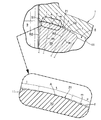
第2実施形態では、第1実施形態のデフケース10の支持面11と、ピニオンギヤ20の背面21(即ち凸曲面f)との間に、支持面11の側に凸に湾曲した球面板状に形成されて弾性変形可能な環状のスラストワッシャ40が介装される。スラストワッシャ40の、支持面11に対向する外側面40aは、第2軸線X2を全部含む横断面(図3参照)で見て支持面11の曲率半径R1よりも大きい曲率半径R4の凸状球面で形成される。
In the second embodiment, a spherical plate that is convexly curved toward the
またスラストワッシャ40の、支持面11とは反対側の内側面40bは、外側面40aと同一又は略同一の曲率半径の球面状に形成される。従って、ピニオンギヤ20の背面21(即ち凸曲面f)の頂部tの曲率半径Rtは、これが接触するスラストワッシャ40の内側面40bの曲率半径よりも小さくなる。
Further, the
そして、ピニオンギヤ20の背面21は、前記横断面で見て両端より離れた背面21の頂部tでのみスラストワッシャ40の内側面40bに接触する。かくして、ピニオンギヤ20の背面21は、頂部tがスラストワッシャ40を介して支持面11に回転摺動可能に支持される。
And the
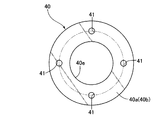
スラストワッシャ40には、スラストワッシャ40の内側面40bがピニオンギヤ20の背面21の頂部tと接触する接触部A′よりも第2軸線X2から遠い側において、複数の貫通孔41が周方向に間隔をおいて設けられる。
The
第2実施形態において、その他の構成は、第1実施形態と同様であるので、図3中、第1実施形態と対応する部分には同一の参照符号を付して、重複する説明を省略する。 In the second embodiment, the other configuration is the same as that of the first embodiment. Therefore, in FIG. 3, parts corresponding to those of the first embodiment are denoted by the same reference numerals, and redundant description is omitted. .
そして、この第2実施形態においても、基本的に第1実施形態と同様の作用効果を達成可能であるが、更に第2実施形態によれば、デフケース10の支持面11と、ピニオンギヤ20の背面21との間に、外側面40aが支持面11側に凸の球面状であるスラストワッシャ40を介装し、且つ外側面40aの曲率半径R4を支持面11の曲率半径R1よりも大きく設定した点に基づき、次のような特有の効果が達成される。
The second embodiment can basically achieve the same functions and effects as those of the first embodiment. However, according to the second embodiment, the
即ち、ピニオンギヤ20のスラスト荷重が比較的小さいときは、スラストワッシャ40は弾性変形量がゼロの状態又は僅少な状態にある。この場合は、図3(a)に示す如くスラストワッシャ40の外側面40aの外周部が支持面11に密着する一方で、外側面40aの内周部と支持面11との間に比較的大きな隙間S3が形成され、且つスラストワッシャ40の内側面40bがピニオンギヤ20の背面21の頂部tに接触することで、内側面40bの外周部及び内周部とピニオンギヤ20の背面21との各間にも少なからず隙間S4,S5が形成される。従って、これら3カ所の隙間S3〜S5に潤滑油を十分に保持させることができるから、スラストワッシャ40と、支持面11及び背面21との接触部に対する潤滑効果が高められる。
That is, when the thrust load of the
また、ピニオンギヤ20のスラスト荷重増大により、スラストワッシャ40がピニオンギヤ20の背面21の頂部tに強く押されて少なからず弾性変形した場合を、図3(b)に例示する。この場合は、スラストワッシャ40の外側面40aの内周部と、支持面11との間の隙間S3が多少縮小されるものの、依然として、上記3カ所で隙間S3〜S5が確保されるため、各々の隙間S3〜S5に潤滑油を保持し続けることができて、上記潤滑効果を維持することができる。更にスラストワッシャ40の内周端縁40eが支持面11や背面21に食い込んだり或いは外周端縁40e′が背面21に食い込んだりして、かじりを生じさせる事態を極力回避できるから、支持面11及び背面21の摩耗抑制、延いては耐久性の向上に寄与することができる。
Further, FIG. 3B illustrates a case where the
更にスラストワッシャ40は、ピニオンギヤ20の背面21の頂部tとの接触部A′よりも第2軸線X2から遠い側に複数の貫通孔41を有しているため、ピニオンギヤ20のスラスト荷重増大によりスラストワッシャ40がピニオンギヤ20の背面21の頂部tに強く押されて、スラストワッシャ40の外側面40aの外周部が支持面11に広く密着しても、その密着部に対し、スラストワッシャ40の内側面40bの外周部から貫通孔41を通じて潤滑油を効率よく供給でき、密着部を良好な潤滑状態に保つことができる。
Further, since the
尚、上記貫通孔41は、貫通孔41無しでも良好な潤滑効果が期待できる場合は、省略可能である。
The through
また、サイドギヤ30の背面31(即ち凸曲面f′)と支持面11との間には、必要に応じて、上記スラストワッシャ40と同様の形状・構成のスラストワッシャ(図示せず)が介装される。その場合には、上述したピニオンギヤ20の背面21の凸曲面fとスラストワッシャ40の特設に基づく作用効果と同等の作用効果が、サイドギヤ30の背面支持構造においても達成可能である。
In addition, a thrust washer (not shown) having the same shape and configuration as the
以上、本発明の実施形態を説明したが、本発明は、上記実施形態に限定されるものではなく、その要旨を逸脱しない範囲で種々の設計変更が可能である。 As mentioned above, although embodiment of this invention was described, this invention is not limited to the said embodiment, A various design change is possible in the range which does not deviate from the summary.
例えば、上記実施形態では、差動装置Dにおけるピニオンギヤ20の背面支持構造とサイドギヤ30の背面支持構造の何れにも本発明を適用したものを示したが、ピニオンギヤ20又はサイドギヤ30の何れか一方の背面支持構造にのみ本発明を適用してもよい。
For example, in the above-described embodiment, the present invention is applied to both the back support structure of the
また上記実施形態では、差動装置Dを自動車のミッションケース1内に収容しているが、差動装置Dは自動車用の差動装置に限定されるものではなく、種々の機械装置用の差動装置として実施可能である。 In the above embodiment, the differential device D is accommodated in the transmission case 1 of the automobile. However, the differential device D is not limited to the differential device for automobiles, and is used for various mechanical devices. It can be implemented as a moving device.
また、差動装置以外の伝動装置であって、回転部材の背面を支持体の球面状の支持面に回転摺動可能に支持させるものにも本発明を適用可能である。 The present invention can also be applied to a transmission device other than the differential device that supports the back surface of the rotating member on the spherical support surface of the support body so as to be able to rotate and slide.
また、上記実施形態では、差動装置Dを、左・右輪伝動系に適用して、左右の駆動軸に対し差動回転を許容しつつ動力を分配するものを示したが、本発明では、差動装置を、前・後輪駆動車両における前・後輪伝動系に適用して、前後の駆動輪に対し差動回転を許容しつつ動力を分配するようにしてもよい。 In the above embodiment, the differential device D is applied to the left and right wheel transmission system to distribute power while allowing differential rotation with respect to the left and right drive shafts. The differential device may be applied to a front / rear wheel transmission system in a front / rear wheel drive vehicle to distribute power while allowing differential rotation to the front and rear drive wheels.
また、上記実施形態では、一対のピニオンギヤ20を、ピニオンギヤ20とは別体の単一のピニオン軸9を介してデフケース10に回転自在に支持するものを示したが、3個以上のピニオンギヤ20を、デフケースの中心部より放射状に延びるピニオン軸を介してデフケースに回転自在に支持してもよく、或いはまた、ピニオンギヤをピニオン軸部と一体に形成して、ピニオン軸部をデフケースに回転自在に支持してもよい。
In the above-described embodiment, a pair of pinion gears 20 is rotatably supported on the differential case 10 via a
また、上記実施形態では、支持体としてのデフケースとして、作業窓付きの、一体型のデフケース10を示したが、本発明では、支持体としてのデフケースを、ボルト等の締結手段で相互間が締結される複数のケース要素(例えば第1,第2ケース半体)より分割構成するようにしてもよい。 Moreover, in the said embodiment, although the integrated differential case 10 with a working window was shown as a differential case as a support body, in this invention, the differential case as a support body is mutually fastened by fastening means, such as a volt | bolt. A plurality of case elements (for example, first and second case halves) may be divided.
A′・・・・・接触部(部位)
f,f′・・・凸曲面
m・・・・・・凸曲面の中点
t,t′・・・頂部
Rt・・・・・頂部の曲率半径
R1・・・・・支持面の曲率半径
R4・・・・・スラストワッシャの外側面の曲率半径
X1・・・・・第1軸線(所定軸線、デフケースの回転軸線)
X2・・・・・第2軸線(所定軸線)
10・・・・・デフケース(支持体)
11・・・・・支持面
20・・・・・ピニオンギヤ(回転部材,第2ベベルギヤ)
21,31・・背面
30・・・・・サイドギヤ(回転部材,第1ベベルギヤ)
40・・・・・スラストワッシャ
40a,40b・・スラストワッシャの外側面,内側面
41・・・・・貫通孔
A '... Contact part (part)
f, f '... convex curved surface m ··· midpoint t, t' of convex curved surface · · · top Rt · · · curvature radius R1 · · · curvature radius of the support surface R4: Radius of curvature X1 on the outer surface of the thrust washer ... First axis (predetermined axis, rotation axis of the differential case)
X2 ... 2nd axis (predetermined axis)
10 ... Differential case (support)
11...
21, 31 ..Back 30... Side gear (rotating member, first bevel gear)
40 ··· Thrust
Claims (5)
前記回転部材(20,30)の前記背面(21,31)は、前記所定軸線(X2,X1)を全部含む横断面で見て、前記所定軸線(X2,X1)を挟んで両側部分が各々、前記支持面(11)の側に膨らむように段差なく滑らかに彎曲した凸曲面(f,f′)を有しており、
前記凸曲面(f,f′)の、前記横断面で見て両端より離れた頂部(t,t′)で前記背面(21,31)が前記支持面(11)に支持されるように、前記横断面で見て少なくとも前記頂部(t,t′)の曲率半径(Rt)が前記支持面(11)の曲率半径(R1)よりも小さく設定されていることを特徴とする、回転部材の支持構造。 A supporting surface (10) that supports the rotating member (20, 30) so as to be rotatable about a predetermined axis (X2, X1). 11), and the support surface of the rotating member is supported by the support surface (11) so that the back surfaces (21, 31) of the rotating member (20, 30) can rotate and slide.
The back surfaces (21, 31) of the rotating member (20, 30) are both cross-sectionally located across the predetermined axis (X2, X1) when viewed in a cross section including the predetermined axis (X2, X1). , Having a convex curved surface (f, f ') smoothly curved without a step so as to swell toward the support surface (11),
The back surface (21, 31) is supported by the support surface (11) at the top portions (t, t ′) of the convex curved surface (f, f ′) that are separated from both ends when viewed in the cross section . A rotating member characterized in that a radius of curvature (Rt) of at least the top portion (t, t ') is set to be smaller than a radius of curvature (R1) of the support surface (11) when viewed in the cross section. Support structure.
前記スラストワッシャ(40)の前記外側面(40a)は、前記横断面で見て前記支持面(11)の曲率半径(R1)よりも大きい曲率半径(R4)に形成されていることを特徴とする、請求項1又は2に記載の回転部材の支持構造。 Between the support surface (11) and the back surface (21), a thrust washer (40) whose outer surface (40a) is a convex spherical shape on the support surface (11) side is interposed,
The outer surface (40a) of the thrust washer (40) is formed to have a radius of curvature (R4) larger than the radius of curvature (R1) of the support surface (11) as seen in the cross section. The support structure for a rotating member according to claim 1 or 2.
Priority Applications (4)
| Application Number | Priority Date | Filing Date | Title |
|---|---|---|---|
| JP2016098173A JP6587975B2 (en) | 2016-05-16 | 2016-05-16 | Support structure for rotating member |
| US15/586,639 US10309511B2 (en) | 2016-05-16 | 2017-05-04 | Support structure for rotating member |
| CN201710324246.8A CN107387718B (en) | 2016-05-16 | 2017-05-10 | Support structure for rotary member |
| DE102017208057.4A DE102017208057B4 (en) | 2016-05-16 | 2017-05-12 | Support structure for rotating element |
Applications Claiming Priority (1)
| Application Number | Priority Date | Filing Date | Title |
|---|---|---|---|
| JP2016098173A JP6587975B2 (en) | 2016-05-16 | 2016-05-16 | Support structure for rotating member |
Publications (3)
| Publication Number | Publication Date |
|---|---|
| JP2017207098A JP2017207098A (en) | 2017-11-24 |
| JP2017207098A5 JP2017207098A5 (en) | 2018-06-14 |
| JP6587975B2 true JP6587975B2 (en) | 2019-10-09 |
Family
ID=60163645
Family Applications (1)
| Application Number | Title | Priority Date | Filing Date |
|---|---|---|---|
| JP2016098173A Active JP6587975B2 (en) | 2016-05-16 | 2016-05-16 | Support structure for rotating member |
Country Status (4)
| Country | Link |
|---|---|
| US (1) | US10309511B2 (en) |
| JP (1) | JP6587975B2 (en) |
| CN (1) | CN107387718B (en) |
| DE (1) | DE102017208057B4 (en) |
Families Citing this family (2)
| Publication number | Priority date | Publication date | Assignee | Title |
|---|---|---|---|---|
| CN107882958A (en) * | 2017-11-25 | 2018-04-06 | 洛阳华冠齿轮股份有限公司 | A kind of new straight-tooth cone tooth spherical surface of planetary gear structure and machining method |
| DE102019216674A1 (en) * | 2019-10-29 | 2021-04-29 | Volkswagen Aktiengesellschaft | Spherical differential gear with geometry to avoid self-excited frictional vibrations |
Family Cites Families (12)
| Publication number | Priority date | Publication date | Assignee | Title |
|---|---|---|---|---|
| JPS5369850U (en) | 1976-11-15 | 1978-06-12 | ||
| JPS57143436U (en) * | 1981-03-04 | 1982-09-08 | ||
| JPS58178014A (en) | 1982-04-13 | 1983-10-18 | Nissan Motor Co Ltd | Thrust washer |
| JPH0452525Y2 (en) * | 1986-10-27 | 1992-12-10 | ||
| JPH05330354A (en) * | 1992-05-30 | 1993-12-14 | Suzuki Motor Corp | Final reduction gear |
| JP2001146952A (en) * | 1999-11-24 | 2001-05-29 | Tochigi Fuji Ind Co Ltd | Pinion washer |
| CA2451893C (en) * | 2002-12-02 | 2013-04-09 | Tesma International Inc. | Differential housing with integrated ring gear |
| JP4957274B2 (en) * | 2007-02-02 | 2012-06-20 | トヨタ自動車株式会社 | Differential device for vehicle |
| CN202451744U (en) | 2012-03-13 | 2012-09-26 | 陕西汉德车桥有限公司 | Bevel gear wheel and vehicle bridge interaxle differential adopting same |
| DE102013217315A1 (en) | 2013-08-30 | 2015-03-05 | Zf Friedrichshafen Ag | differential gear |
| DE102014000499B4 (en) * | 2014-01-16 | 2022-08-11 | Mercedes-Benz Group AG | Differential gear for a motor vehicle with at least one thin-walled carrier element in a lightweight construction |
| JP6866690B2 (en) * | 2017-02-28 | 2021-04-28 | 株式会社ジェイテクト | Differential device |
-
2016
- 2016-05-16 JP JP2016098173A patent/JP6587975B2/en active Active
-
2017
- 2017-05-04 US US15/586,639 patent/US10309511B2/en active Active
- 2017-05-10 CN CN201710324246.8A patent/CN107387718B/en not_active Ceased
- 2017-05-12 DE DE102017208057.4A patent/DE102017208057B4/en active Active
Also Published As
| Publication number | Publication date |
|---|---|
| DE102017208057B4 (en) | 2024-05-08 |
| DE102017208057A1 (en) | 2017-11-16 |
| US20170328459A1 (en) | 2017-11-16 |
| US10309511B2 (en) | 2019-06-04 |
| CN107387718B (en) | 2020-09-18 |
| CN107387718A (en) | 2017-11-24 |
| JP2017207098A (en) | 2017-11-24 |
Similar Documents
| Publication | Publication Date | Title |
|---|---|---|
| JP4699470B2 (en) | Eccentric rocking speed reducer | |
| US10125855B2 (en) | Transmission device | |
| JP2017053385A (en) | Power transmission device for vehicle | |
| JP6479259B2 (en) | Planetary gear device and wheel drive device | |
| JP4828847B2 (en) | Differential equipment | |
| JP6587975B2 (en) | Support structure for rotating member | |
| JP6169004B2 (en) | Eccentric rocking speed reducer | |
| CN107642591B (en) | Support portion lubricating structure for gear member and differential device | |
| JP6021694B2 (en) | Wheel drive series | |
| US20140260743A1 (en) | Wheel driving apparatus | |
| WO2020137925A1 (en) | In-wheel motor drive device | |
| JPH1047456A (en) | Differential-limiting mechanism for differential gear | |
| WO2017170588A1 (en) | Gearing | |
| WO2017170587A1 (en) | Gearing | |
| JP5143718B2 (en) | Rotating device | |
| WO2018110004A1 (en) | Differential device | |
| JP2019086053A (en) | Differential device | |
| WO2020153332A1 (en) | Differential device | |
| JP2018084281A (en) | Toroidal type non-stage transmission | |
| CN116495049A (en) | Steering device for vehicle | |
| US20240011564A1 (en) | Wheel drive device | |
| JP7082035B2 (en) | Differential device | |
| JP6804341B2 (en) | Needle roller with cage and planetary gear mechanism support structure with it | |
| JP6867845B2 (en) | Differential device | |
| JP2019086052A (en) | Differential device |
Legal Events
| Date | Code | Title | Description |
|---|---|---|---|
| A521 | Request for written amendment filed |
Free format text: JAPANESE INTERMEDIATE CODE: A523 Effective date: 20180423 |
|
| A621 | Written request for application examination |
Free format text: JAPANESE INTERMEDIATE CODE: A621 Effective date: 20180423 |
|
| A977 | Report on retrieval |
Free format text: JAPANESE INTERMEDIATE CODE: A971007 Effective date: 20190220 |
|
| A131 | Notification of reasons for refusal |
Free format text: JAPANESE INTERMEDIATE CODE: A131 Effective date: 20190227 |
|
| A521 | Request for written amendment filed |
Free format text: JAPANESE INTERMEDIATE CODE: A523 Effective date: 20190423 |
|
| TRDD | Decision of grant or rejection written | ||
| A01 | Written decision to grant a patent or to grant a registration (utility model) |
Free format text: JAPANESE INTERMEDIATE CODE: A01 Effective date: 20190815 |
|
| A61 | First payment of annual fees (during grant procedure) |
Free format text: JAPANESE INTERMEDIATE CODE: A61 Effective date: 20190911 |
|
| R150 | Certificate of patent or registration of utility model |
Ref document number: 6587975 Country of ref document: JP Free format text: JAPANESE INTERMEDIATE CODE: R150 |
|
| R250 | Receipt of annual fees |
Free format text: JAPANESE INTERMEDIATE CODE: R250 |
|
| R250 | Receipt of annual fees |
Free format text: JAPANESE INTERMEDIATE CODE: R250 |
|
| R250 | Receipt of annual fees |
Free format text: JAPANESE INTERMEDIATE CODE: R250 |