JP6587532B2 - Vehicle seat - Google Patents
Vehicle seat Download PDFInfo
- Publication number
- JP6587532B2 JP6587532B2 JP2015241040A JP2015241040A JP6587532B2 JP 6587532 B2 JP6587532 B2 JP 6587532B2 JP 2015241040 A JP2015241040 A JP 2015241040A JP 2015241040 A JP2015241040 A JP 2015241040A JP 6587532 B2 JP6587532 B2 JP 6587532B2
- Authority
- JP
- Japan
- Prior art keywords
- pad
- back panel
- vehicle seat
- blower
- seat
- Prior art date
- Legal status (The legal status is an assumption and is not a legal conclusion. Google has not performed a legal analysis and makes no representation as to the accuracy of the status listed.)
- Active
Links
Images


Classifications
-
- A—HUMAN NECESSITIES
- A47—FURNITURE; DOMESTIC ARTICLES OR APPLIANCES; COFFEE MILLS; SPICE MILLS; SUCTION CLEANERS IN GENERAL
- A47C—CHAIRS; SOFAS; BEDS
- A47C7/00—Parts, details, or accessories of chairs or stools
- A47C7/62—Accessories for chairs
- A47C7/72—Adaptations for incorporating lamps, radio sets, bars, telephones, ventilation, heating or cooling arrangements or the like
- A47C7/74—Adaptations for incorporating lamps, radio sets, bars, telephones, ventilation, heating or cooling arrangements or the like for ventilation, heating or cooling
-
- B—PERFORMING OPERATIONS; TRANSPORTING
- B60—VEHICLES IN GENERAL
- B60H—ARRANGEMENTS OF HEATING, COOLING, VENTILATING OR OTHER AIR-TREATING DEVICES SPECIALLY ADAPTED FOR PASSENGER OR GOODS SPACES OF VEHICLES
- B60H1/00—Heating, cooling or ventilating [HVAC] devices
-
- B—PERFORMING OPERATIONS; TRANSPORTING
- B60—VEHICLES IN GENERAL
- B60N—SEATS SPECIALLY ADAPTED FOR VEHICLES; VEHICLE PASSENGER ACCOMMODATION NOT OTHERWISE PROVIDED FOR
- B60N2/00—Seats specially adapted for vehicles; Arrangement or mounting of seats in vehicles
- B60N2/56—Heating or ventilating devices
Description
本発明は車両用シートに関し、特に、送風器構を設けた車両用シートに関する。 The present invention relates to a vehicle seat, and more particularly to a vehicle seat provided with a blower structure.
車両用シートに送風器構を設けた構成として、特開2011−130977号公報(特許文献1)には、通気溝が形成されたパッドと、パッドに装着されて通気溝を覆う蓋部材と、蓋部材に形成された蓋穴を介して通気溝と連通されるダクトを有する乗物用シートが記載されている。そして、ダクトは、蓋穴の外周に位置する蓋部材の蓋穴外周部をパッドに押しつつパッドに取付けられるフランジ部を有することが記載されている。 As a configuration in which a blower structure is provided in a vehicle seat, Japanese Patent Application Laid-Open No. 2011-130977 (Patent Document 1) includes a pad in which a ventilation groove is formed, a lid member that is attached to the pad and covers the ventilation groove, A vehicle seat having a duct communicating with a ventilation groove through a lid hole formed in the lid member is described. And it is described that a duct has a flange part attached to a pad, pressing the cover hole outer peripheral part of the cover member located in the outer periphery of a cover hole to a pad.
車両用シートのパッドは弾力性があり、搭乗者が着座すると、搭乗者の体重がかかって圧縮変形する。この時、特許文献1に記載されているようなパッドに形成された通気溝も変形する。そして、変形の度合いによっては、通気溝が押しつぶされて通気性を確保できなくなってしまう可能性がある。
The pad of the vehicle seat is elastic, and when the occupant sits down, the occupant's weight is applied and it is compressed and deformed. At this time, the ventilation groove formed in the pad as described in
その結果、パッドに対して搭乗者が着座する側と反対の側に設置した送風装置から風を送り続けても、パッドを介して搭乗者の側に送風装置から送られた空気が届かなくなってしまうか、または届いてもその風量が大幅に減少されたものになってしまう可能性がある。 As a result, even if the wind continues to be sent from the air blower installed on the side opposite to the side on which the passenger is seated with respect to the pad, the air sent from the air blower does not reach the passenger side via the pad. Or even if it arrives, the air volume may be significantly reduced.
そこで、本発明では、車両用シートに搭乗者が着座した状態でも送風器から送り出された空気をパッドの搭乗者が着座している面の側に確実に送風することを可能にした車両用シートを提供する。 Therefore, in the present invention, even when the occupant is seated on the vehicle seat, the air sent from the blower can be reliably blown to the side of the pad on which the occupant is seated. I will provide a.
上記した課題を解決するために、本発明では、シートクッションとシートバックと、ヘ
ッドレストとを備えた車両用シートにおいて、シートバックは、パッドと、パッドの表面
を覆うシートカバーと、送風器と、この送風器を内部に装着すると共にパッドの裏面を支えて送風器から送り出された空気の通り道である流路が形成されている樹脂で形成されたバックパネルと、パッドとバックパネルを支持するフレームと、バックパネルとフレームとを接続する弾性体とを備えて構成した。
In order to solve the above-described problems, in the present invention, in a vehicle seat including a seat cushion, a seat back, and a headrest, the seat back includes a pad, a seat cover that covers the surface of the pad, a blower, A back panel formed of a resin in which a flow path that is a passage for air sent from the blower while supporting the back surface of the pad is mounted and the pad and the back panel are supported. And an elastic body that connects the back panel and the frame .
本発明によれば、車両用シートに搭乗者が着座した状態でも送風器から送り出された空気をパッドの搭乗者が着座している面の側に確実に送風することが可能になり、シートに熱がこもるのを防止できるようになった。 According to the present invention, even when the passenger is seated on the vehicle seat, the air sent from the blower can be reliably blown to the side of the pad on which the passenger is seated. It became possible to prevent heat from accumulating.
本発明は、車両用シートにおいて、シートの裏面側から送風器で送り出された空気を、シートのパッドの外側に形成された流路を通してパッドからシートの表面に送り出すような構成にすることにより、搭乗者がシートに着座することによりパッドが変形しても空気の流路を確保できるようにしたものである。 In the vehicle seat, the air sent from the back side of the seat by the blower is configured to be sent out from the pad to the surface of the seat through a flow path formed outside the seat pad. The air flow path can be secured even if the pad is deformed by the passenger sitting on the seat.
本実施の形態を説明するための全図において同一機能を有するものは同一の符号を付すようにし、その繰り返しの説明は原則として省略する。以下、本発明の実施の形態を図面に基づいて詳細に説明する。 Components having the same function are denoted by the same reference symbols throughout the drawings for describing the embodiments, and the repetitive description thereof is omitted in principle. Hereinafter, embodiments of the present invention will be described in detail with reference to the drawings.
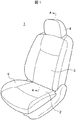
図1は、本発明で対象とする車両用シート1の基本的な構成を示す。車両用シート1は、搭乗者が着座するシートクッション2、シートクッションに着座した搭乗者が背中をもたれ掛けるシートバック3、搭乗者の頭部を支えるヘッドレスト4、サイドサポート5を備えている。
FIG. 1 shows a basic configuration of a
図2は、シートバック3の表面を覆うシートカバーを外してウレタンなどで形成されたパッド31を露出させた状態の図である。パッド31には、通風用の穴32が多数形成されている。
FIG. 2 is a view showing a state in which the
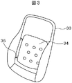
図3は、図2の状態からパッド31を取り外したもので、フレーム33にバックパネル34がばねなどの弾性体35で支持されている状態を示している。バックパネル34は、樹脂で形成されており、外力が加わっても大きく変形することはない。
FIG. 3 shows a state in which the
バックパネル34を図3の状態における裏面側から見た状態を図4に示す。バックパネル34の上部には、送風器41が固定されており、送風器41の送風口42がバックパネル34の送風器接続口341に嵌め込まれて固定されている。
FIG. 4 shows a state in which the
図4におけるバックパネル34のB−B断面を、図5に示す。バックパネル34はベース部342とカバー部343とで袋状の二重構造になっていて、上部の送風器接続口341に送風器41が取り付けられている。バックパネル34は樹脂を用いてブロー成形により形成する。ベース部342がばねなどの弾性体35でフレーム33に支持されている。
FIG. 5 shows a BB cross section of the
ベース部342には、空気排出用の排気口344が複数形成されている。排気口344の回りにはボス345が形成されている。カバー部343は、周囲がベース部342と接続しており、送風器接続口341と排気口344を除いてベース部342との間に閉じた空間を形成している。
The
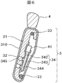
図6は、図1のA−A断面で、パッド31に形成された通風用の穴32にバックパネルに形成されたボス345がはめ込まれ多状態でバックパネル34がばね35(図3参照)でフレーム33に支持されている状態を示している。パッド31の表面は、通気性を有するシートカバー310で覆われている。実際には、シートカバー310は、複数の部材に分割されてパッド31の表面を覆っているが、ここでは簡略化して示している。
FIG. 6 is a cross-sectional view taken along the line AA of FIG. The state supported by the
図6の状態で、送風器41を作動させると、送風器41から送風器接続口341を介してバックパネルの内部、即ちベース部342とカバー部343とで形成される空間の内部に空気が送り込まれる。このベース部342とカバー部343とで形成される空間は送り込まれた空気の流路を形成する。
When the
図4乃至図6に示した構成と異なり、送風器41をバックパネル34以外の部分に固定した場合、搭乗者がバックシート3にもたれかかることによりバックパネル34の位置が変化することに対応するために、送風器41とバックパネル34に形成した空気の流路とを繋ぐ部材には柔軟性が要求され、例えば蛇腹構造の接続部材を用いる必要がある。
Unlike the configuration shown in FIGS. 4 to 6, when the
これに対して、本実施例では、送風器41をバックパネル34に直接取り付けた構造としたことにより、搭乗者がバックシート3にもたれかかることによりバックパネル34の位置が変化した場合であっても、送風器41とバックパネル34に形成した空気の流路との位置関係は常に一定に保たれている。また、送風器41とバックパネル34に形成した空気の流路とを繋ぐ部材を不要とし、部品点数を減らすことができる。更に、送風器41とバックパネル34との間に送風抵抗となるダクトなどの接続部材を必要としなくなったので、バックシート3の表面に送り出す空気の量を確保することができるようになった。
On the other hand, in the present embodiment, the structure in which the
送風器41から送り込まれた空気は、この流路を通って排気口344からパッド31に形成された通風用の穴32から孔の表面を覆うシートカバー310を通って外部に排出される。このとき、シート1に着座してシートバック3に背をもたれている搭乗者の背中及びその周辺の熱が除去される。これにより、シートバック3に熱がこもるのが防止され、シートバック3に背をもたれている搭乗者の爽快感を増すことができる。
The air sent from the
図6に示したような構成において、シート1に着座した搭乗者がシートバック3に背をもたれたとき、弾力性のあるパッド31は圧縮されて変形する。これによりパッド31に形成された通風用の穴32も、ほぼ穴32の中心軸方向に変形する。
In the configuration as shown in FIG. 6, when a passenger seated on the
一方、バックパネル34は、ベース部342がばねなどの弾性体35でフレーム33に支持されているので、シート1に着座した搭乗者がシートバック3に背をもたれてパッド31が変形しても、カバー部343にはほとんど力が加わらない。したがって、ベース部342とカバー部343とで形成される空気の流路はほとんど変形せず、搭乗者がシートバック3に背をもたれてもベース部342とカバー部343とで形成された流路は確保される。
On the other hand, since the
その結果、送風器41から送風器接続口341を介して送り出された空気は、ベース部342とカバー部343とで形成された流路を経由して通風用の穴32からシートバック3の表面から安定して吹き出され、シートバック3に背をもたれている搭乗者の爽快感を損なうことなく、快適な状態で着座し続けることができる。
As a result, the air sent out from the
また、ベース部342に形成したボス345はパッド31に形成した通風用の穴32に緩く嵌合した状態であるので、ベース部342に形成した排気口344とパッド31に形成した通風用の穴32の位置がずれることが防止され、シートバック3の表面からの空気の吹き出しを安定して行うことができる。
Further, since the
本実施例によれば、バックパネル34の送風器接続口341に送風器41を直接取り付ける構造としたので、バックパネル34と送風器41との間を接続する新たな部材を必要とせず、従来技術と比べて構成を簡素化することができた。
According to the present embodiment, since the
また、本実施例によれば、送風器41から送り出された空気を安定してシートバック3の表面から排出できるので、搭乗者が車両用シート1に長時間着座し続けても、搭乗者の爽快感を長時間維持させることができる。また、搭乗者の体重の軽重に係らず、送風器41から送り出された空気を安定してシートバック3の表面から排出できる。
Further, according to the present embodiment, the air sent out from the
なお、図4に示したバックパネル34は、ベース部342とカバー部343とで一つの大きな空間を形成してそれを流路とする構成であったが、図7に示すように、排気口344の列ごとに空間を仕切る形状にしてもよい。すなわち、図5に示したような、ベース部342とカバー部343とで形成する空間を、カバー部343‐1を図7に示すような形状にして、排気口344の列ごとに凸部343−11,343−12,343−13を形成するようにしてもよい。
The
このように凸部343−11,343−12,343−13を形成することにより、カバー部343‐1全体の曲げ強度を増すことができる。その結果、シート1に着座した搭乗者がシートバック3に背をもたれてパッド31が変形した場合であっても、カバー部343−1の変形量をより小さく抑えることができ、ベース部342とカバー部343−1とで形成する空間を確保することができる。
Thus, by forming the convex portions 343-11, 343-12, and 343-13, the bending strength of the entire cover portion 343-1 can be increased. As a result, even when the passenger seated on the
なお、本実施例では、シートバック3の構成について説明したが、シートクッション2にも同様な構成を設けることができる。
In the present embodiment, the configuration of the seat back 3 has been described, but a similar configuration can be provided for the
実施例1においては、バックパネル34をベース部342とカバー部342とで空間を作って空気の流路を形成する構成となっていたが、本実施例ではカバー部342を形成せずにベース部342であるバックパネル34本体を凹凸に成形して空気の流路を形成するようにした。
In the first embodiment, the
図8に、本実施例に係るバックパネル60に送風器41が装着された状態の正面図を示す。また、図9には図8におけるC−C断面の矢視図を、図10にはD−D断面の矢視図を示す。また、図11には、図8に示したバックパネル60を、裏面から見た図を示す。
In FIG. 8, the front view of the state by which the
バックパネル60には、送風器接続口61が形成されており、送風器41の送風口42が送風器接続口61に嵌め込まれて固定されている。また、バックパネル60には、図8に示すように、送風器接続口61に繋がる凸部62が複数形成されている。凸部62の断面は、図10に示すような形状をしており、バックパネル60の各凸部62と反対側の面には、突起63が形成されている。突起63は、図11に示すように、凸部62の周囲に形成されている。
A
図12に、図1のA−A断面に相当する本実施例のシートバック3の断面を示す。バックパネル60をパッド31に押し当てた状態で、バックパネル60に形成した突起63がパッド31に密着してバックパネル60の凸部62とパッド31の表面で閉じた空間を形成し、送風器41から送り出された空気の通風路を形成している。本実施例のバックパネル60には、実施例1で説明したような、パッド31に形成された通風用の穴32のそれぞれに対応した排気口344を有さず、同じ列に並ぶ複数の通風用の穴32の上に凸部62により通風路が形成される。
FIG. 12 shows a cross section of the seat back 3 of the present embodiment corresponding to the AA cross section of FIG. With the
すなわち、図12に示した状態で送風器41から送り出された空気は、バックパネル60の凸部62とパッド31の表面とで構成された閉じた空間を流路を通ってパッド31に形成された通風用の穴32から孔の表面を覆うシートカバー310を通って外部に排出される。このとき、シート1に着座してシートバック3に背をもたれている搭乗者の背中及びその周辺の熱が除去される。これにより、シートバック3に熱がこもるのが防止され、シートバック3に背をもたれている搭乗者の爽快感を増すことができる。
That is, the air sent out from the
図12に示したような構成において、シート1に着座した搭乗者がシートバック3に背をもたれたとき、弾力性のあるパッド31は圧縮されて変形する。これによりパッド31に形成された通風用の穴32も、ほぼ穴32の中心軸方向に変形する。
In the configuration as shown in FIG. 12, when a passenger sitting on the
一方、バックパネル60は、実施例1で説明したように、ばねなどの弾性体35でフレーム33に支持されているので、シート1に着座した搭乗者がシートバック3に背をもたれてパッド31が変形しても、バックパネル60にはほとんど力が加わらない。したがって、バックパネル60の凸部62とパッド31の表面とで形成される空気の流路はほとんど変形せず、搭乗者がシートバック3に背をもたれても流路は確保される。
On the other hand, as described in the first embodiment, the
その結果、送風器41から送風器接続口61を介して送り出された空気は、バックパネル60の凸部62とパッド31の表面とで形成された流路を経由して通風用の穴32からシートバック3の表面のへ側に安定して吹き出され、シートバック3に背をもたれている搭乗者の爽快感を損なうことなく、快適な状態で着座し続けることができる。
As a result, the air sent out from the
本実施例によれば、バックパネル60の送風器接続口61に送風器41を直接取り付ける構造としたので、バックパネル60と送風器41との間を接続する新たな部材を必要とせず、従来技術と比べて構成を簡素化することができた。
According to the present embodiment, since the
また、本実施例によれば、送風器41から送り出された空気を安定してシートバック3の表面から排出できるので、搭乗者が車両用シート1に長時間着座し続けても、搭乗者の爽快感を長時間維持させることができる。また、搭乗者の体重の軽重に係らず、送風器41から送り出された空気を安定してシートバック3の表面から排出できる。
Further, according to the present embodiment, the air sent out from the
なお、バックパネル60に形成した突起63をパッド31に押し当てることでバックパネル60の凸部62とパッド31とで形成する通風路の密閉性を高める構造について説明したが、本実施例はこれに限られるものではない。
In addition, although the structure which improves the airtightness of the ventilation path formed by the
例えば、図13に示したように、バックパネル70に図9のような突起63を無くして、バックパネル70の周辺部分71を外側(図13では左側)に少し折り曲げた構造としてもよい。図13に示したような構造とすることにより、バックパネル70をパッド31に押付けたときに、バックパネル70の周辺部分71とパッド31との間に、バックパネル70の前面に亘る閉じた空間が形成される。この閉じた空間に送風器41から送り出された空気は、凸部71とパッド31の間に形成された空間を流路としてパッド31に形成された通風用の穴32からシートバック3の表面のへ側に安定して吹き出すことができる。
For example, as illustrated in FIG. 13, the
また、図14に示したように、バックパネル80の周辺部分を蛇腹構造81としてもよい。図14に示したような構造とすることにより、バックパネル80をパッド31に押付けたときに、バックパネル80の周辺部分に形成した蛇腹構造81とパッド31との間に、バックパネル80の前面に亘る閉じた空間が形成される。この閉じた空間に送風器41から送り出された空気は、凸部81とパッド31の間に形成された空間を流路としてパッド31に形成された通風用の穴32からシートバック3の表面のへ側に安定して吹き出すことができる。
As shown in FIG. 14, the peripheral portion of the
なお、本実施例では、シートバック3の構成について説明したが、シートクッション2にも同様な構成を設けることができる。
In the present embodiment, the configuration of the seat back 3 has been described, but a similar configuration can be provided for the
以上、本発明者によってなされた発明を実施例に基づき具体的に説明したが、本発明は前記実施例に限定されるものではなく、その要旨を逸脱しない範囲で種々変更可能であることは言うまでもない。例えば、上記した実施例は本発明を分かりやすく説明するために詳細に説明したものであり、必ずしも説明した全ての構成を備えるものに限定されるものではない。また、各実施例の構成の一部について、他の構成の追加・削除・置換をすることが可能である。 As mentioned above, although the invention made by the present inventor has been specifically described based on the embodiments, it is needless to say that the present invention is not limited to the above embodiments and can be variously modified without departing from the gist thereof. Yes. For example, the above-described embodiments have been described in detail for easy understanding of the present invention, and are not necessarily limited to those having all the configurations described. Further, it is possible to add, delete, and replace other configurations for a part of the configuration of each embodiment.
1・・・車両用シート 2・・・シートクッション 3・・・シートバック 4・・・ヘッドレスト 5・・・サイドサポート 31・・・パッド 32・・・通風用の穴 33・・・フレーム 34,34−1,60,70,80・・・バックパネル 41・・・送風器 62,72,82・・・凸部 342・・・ベース部 343・・・カバー部 344・・・排気口 345・・・ボス
DESCRIPTION OF
Claims (9)
前記シートバックは、
パッドと、
前記パッドの表面を覆うシートカバーと、
送風器と、
前記送風器を内部に装着すると共に前記パッドの裏面を支えて前記送風器から送り出された空気の通り道である流路が形成されている樹脂で形成されたバックパネルと、
前記パッドと前記バックパネルを支持するフレームと、
前記バックパネルと前記フレームとを接続する弾性体と
を備えていることを特徴とする車両用シート。 A vehicle seat including a seat cushion, a seat back, and a headrest,
The seat back is
Pad,
A sheet cover covering the surface of the pad;
A blower,
A back panel formed of a resin in which a flow path that is a passage for air sent from the blower while supporting the back surface of the pad is mounted inside the blower,
A frame that supports the pad and the back panel ;
A vehicle seat comprising: an elastic body that connects the back panel and the frame .
ックパネルと前記パッドとの間に形成されていることを特徴とする車両用シート。 The vehicle seat according to claim 1, wherein the flow path is formed inside the back panel or between the back panel and the pad.
成された前記流路と重なる位置に通気孔が形成されていることを特徴とする車両用シート
。 The vehicle seat according to claim 1 or 2, a vehicle seat, characterized in that the said pad has vent hole is formed at a position overlapping with the passage formed in the back panel.
ており、前記バックパネルの前記袋状に形成された前記流路の前記パッドに形成された通
気孔に対向する位置に排気口が形成されていることを特徴とする車両用シート。 The vehicle seat according to claim 3, wherein the flow path is formed in the pad of the back panel is formed into a bag shape, the flow path in which the bag shape formed of said back panel through A vehicle seat characterized in that an exhaust port is formed at a position facing the air hole.
ッドに接する側の周囲にはボスが形成されており、前記ボスが前記パッドの通気孔に嵌め
込まれていることを特徴とする車両用シート。 The vehicle seat according to claim 4, wherein a boss is formed around a side of the exhaust port formed in the back panel that contacts the pad, and the boss is fitted into a vent hole of the pad. A vehicle seat characterized by comprising:
て形成された部分と前記パッドとの間で形成されていることを特徴とする車両用シート。 4. The vehicle seat according to claim 3, wherein the flow path is formed between a portion formed by forming the back panel into a concavo-convex shape and the pad. 5.
路を形成している部分の前記パッドに接する側で前記流路の周囲に前記パッドの側に突き
出した突起が形成されていることを特徴とする車両用シート。 The vehicle seat according to claim 6, protrudes to the side of the pad around the flow path on the side in contact with the pad portion forming the flow path between the pads of the back panel A vehicle seat characterized in that a protrusion is formed.
の前記周辺部の以外の部分と比べて前記パッドの側に突き出していることを特徴とする車
両用シート。 The vehicle seat according to claim 6, wherein a peripheral portion of the back panel protrudes toward the pad as compared with a portion other than the peripheral portion of the back panel.
いることを特徴とする車両用シート。 The vehicle seat according to claim 6, wherein a peripheral portion of the back panel has a bellows structure.
Priority Applications (2)
| Application Number | Priority Date | Filing Date | Title |
|---|---|---|---|
| JP2015241040A JP6587532B2 (en) | 2015-12-10 | 2015-12-10 | Vehicle seat |
| PCT/JP2016/085643 WO2017098984A1 (en) | 2015-12-10 | 2016-11-30 | Automobile seat |
Applications Claiming Priority (1)
| Application Number | Priority Date | Filing Date | Title |
|---|---|---|---|
| JP2015241040A JP6587532B2 (en) | 2015-12-10 | 2015-12-10 | Vehicle seat |
Publications (3)
| Publication Number | Publication Date |
|---|---|
| JP2017105335A JP2017105335A (en) | 2017-06-15 |
| JP2017105335A5 JP2017105335A5 (en) | 2018-09-13 |
| JP6587532B2 true JP6587532B2 (en) | 2019-10-09 |
Family
ID=59014074
Family Applications (1)
| Application Number | Title | Priority Date | Filing Date |
|---|---|---|---|
| JP2015241040A Active JP6587532B2 (en) | 2015-12-10 | 2015-12-10 | Vehicle seat |
Country Status (2)
| Country | Link |
|---|---|
| JP (1) | JP6587532B2 (en) |
| WO (1) | WO2017098984A1 (en) |
Family Cites Families (5)
| Publication number | Priority date | Publication date | Assignee | Title |
|---|---|---|---|---|
| JPH0385950U (en) * | 1989-12-19 | 1991-08-30 | ||
| SE504942C2 (en) * | 1995-09-14 | 1997-06-02 | Walinov Ab | Device for ventilating a vehicle seat |
| JP5377895B2 (en) * | 2008-06-23 | 2013-12-25 | トヨタ紡織株式会社 | Vehicle seat provided with a ventilation device |
| JP5343503B2 (en) * | 2008-10-14 | 2013-11-13 | 株式会社デンソー | Seat and seat air conditioner |
| JP6095434B2 (en) * | 2013-03-22 | 2017-03-15 | 日本発條株式会社 | Vehicle seat |
-
2015
- 2015-12-10 JP JP2015241040A patent/JP6587532B2/en active Active
-
2016
- 2016-11-30 WO PCT/JP2016/085643 patent/WO2017098984A1/en active Application Filing
Also Published As
| Publication number | Publication date |
|---|---|
| JP2017105335A (en) | 2017-06-15 |
| WO2017098984A1 (en) | 2017-06-15 |
Similar Documents
| Publication | Publication Date | Title |
|---|---|---|
| US8585137B2 (en) | Vehicle seat for cooling and heating | |
| US11932141B2 (en) | Vehicle seat | |
| US9073466B2 (en) | Vehicle seat | |
| JP5377895B2 (en) | Vehicle seat provided with a ventilation device | |
| JP5505404B2 (en) | Vehicle seat device | |
| US20180065525A1 (en) | Vehicle seat | |
| WO2017110529A1 (en) | Vehicle seat | |
| US11571997B2 (en) | Seat component for a vehicle seat and vehicle seat | |
| CN210062743U (en) | Vehicle seat | |
| CN110303958B (en) | Vehicle seat | |
| JP6587532B2 (en) | Vehicle seat | |
| JP5499698B2 (en) | Vehicle seat | |
| JP6643726B2 (en) | Vehicle seat | |
| JP5784946B2 (en) | Vehicle seat | |
| US11247589B2 (en) | Vehicle seat | |
| JP4322877B2 (en) | Air conditioning unit | |
| JP6838429B2 (en) | Air conditioning sheet | |
| JP7428885B2 (en) | vehicle seat | |
| JP2012192761A (en) | Vehicular seat | |
| JP6643727B2 (en) | Vehicle seat | |
| JP6652713B2 (en) | Vehicle seat | |
| JP7121259B2 (en) | Arrangement structure of sensors on seat and vehicle seat | |
| JP2018149886A (en) | Seat cushion structure of vehicle seat | |
| KR20170027231A (en) | Vehicle Seat For Cooling And Heating | |
| KR101781476B1 (en) | Ventilation seat apparatus for vehicle |
Legal Events
| Date | Code | Title | Description |
|---|---|---|---|
| A521 | Request for written amendment filed |
Free format text: JAPANESE INTERMEDIATE CODE: A523 Effective date: 20180806 |
|
| A621 | Written request for application examination |
Free format text: JAPANESE INTERMEDIATE CODE: A621 Effective date: 20180806 |
|
| A131 | Notification of reasons for refusal |
Free format text: JAPANESE INTERMEDIATE CODE: A131 Effective date: 20190604 |
|
| A521 | Request for written amendment filed |
Free format text: JAPANESE INTERMEDIATE CODE: A523 Effective date: 20190712 |
|
| TRDD | Decision of grant or rejection written | ||
| A01 | Written decision to grant a patent or to grant a registration (utility model) |
Free format text: JAPANESE INTERMEDIATE CODE: A01 Effective date: 20190903 |
|
| A61 | First payment of annual fees (during grant procedure) |
Free format text: JAPANESE INTERMEDIATE CODE: A61 Effective date: 20190910 |
|
| R150 | Certificate of patent or registration of utility model |
Ref document number: 6587532 Country of ref document: JP Free format text: JAPANESE INTERMEDIATE CODE: R150 |
|
| R250 | Receipt of annual fees |
Free format text: JAPANESE INTERMEDIATE CODE: R250 |
|
| R250 | Receipt of annual fees |
Free format text: JAPANESE INTERMEDIATE CODE: R250 |
|
| S531 | Written request for registration of change of domicile |
Free format text: JAPANESE INTERMEDIATE CODE: R313531 |
|
| R350 | Written notification of registration of transfer |
Free format text: JAPANESE INTERMEDIATE CODE: R350 |