JP6585534B2 - Small excavator - Google Patents
Small excavator Download PDFInfo
- Publication number
- JP6585534B2 JP6585534B2 JP2016064096A JP2016064096A JP6585534B2 JP 6585534 B2 JP6585534 B2 JP 6585534B2 JP 2016064096 A JP2016064096 A JP 2016064096A JP 2016064096 A JP2016064096 A JP 2016064096A JP 6585534 B2 JP6585534 B2 JP 6585534B2
- Authority
- JP
- Japan
- Prior art keywords
- cover
- seal
- plate
- prime mover
- edge
- Prior art date
- Legal status (The legal status is an assumption and is not a legal conclusion. Google has not performed a legal analysis and makes no representation as to the accuracy of the status listed.)
- Active
Links
Images


Classifications
-
- B—PERFORMING OPERATIONS; TRANSPORTING
- B60—VEHICLES IN GENERAL
- B60R—VEHICLES, VEHICLE FITTINGS, OR VEHICLE PARTS, NOT OTHERWISE PROVIDED FOR
- B60R13/00—Elements for body-finishing, identifying, or decorating; Arrangements or adaptations for advertising purposes
- B60R13/06—Sealing strips
-
- B—PERFORMING OPERATIONS; TRANSPORTING
- B62—LAND VEHICLES FOR TRAVELLING OTHERWISE THAN ON RAILS
- B62D—MOTOR VEHICLES; TRAILERS
- B62D21/00—Understructures, i.e. chassis frame on which a vehicle body may be mounted
- B62D21/18—Understructures, i.e. chassis frame on which a vehicle body may be mounted characterised by the vehicle type and not provided for in groups B62D21/02 - B62D21/17
-
- E—FIXED CONSTRUCTIONS
- E02—HYDRAULIC ENGINEERING; FOUNDATIONS; SOIL SHIFTING
- E02F—DREDGING; SOIL-SHIFTING
- E02F9/00—Component parts of dredgers or soil-shifting machines, not restricted to one of the kinds covered by groups E02F3/00 - E02F7/00
- E02F9/16—Cabins, platforms, or the like, for drivers
Landscapes
- Engineering & Computer Science (AREA)
- Mechanical Engineering (AREA)
- Mining & Mineral Resources (AREA)
- Civil Engineering (AREA)
- General Engineering & Computer Science (AREA)
- Structural Engineering (AREA)
- Chemical & Material Sciences (AREA)
- Combustion & Propulsion (AREA)
- Transportation (AREA)
- Component Parts Of Construction Machinery (AREA)
- Seal Device For Vehicle (AREA)
- Body Structure For Vehicles (AREA)
Description
本発明は、原動機の上側に座席が配置された小型の油圧ショベルに関する。 The present invention relates to a small hydraulic excavator in which a seat is disposed on the upper side of a prime mover.
一般に、小型の油圧ショベルは、自走可能な下部走行体と、前記下部走行体上に旋回可能に搭載された上部旋回体と、前記上部旋回体の前,後方向の前側に俯仰動可能に設けられたフロント装置とにより構成されている。 In general, a small hydraulic excavator is capable of self-propelled lower traveling body, an upper revolving body that is pivotably mounted on the lower traveling body, and can be raised and lowered in front of and behind the upper revolving body. It is comprised with the provided front apparatus.
ここで、小型の油圧ショベルは、通常ミニショベルと呼ばれるもので、建物の内部での解体作業、狭い街路地等での掘削作業等に用いられる。このため、小型の油圧ショベルは、例えば機械重量が0.7〜8トン程度までに抑えられている。従って、小型の油圧ショベルは、下部走行体、上部旋回体を含む車体全体がコンパクトに形成されている。 Here, the small hydraulic excavator is usually called a mini excavator, and is used for dismantling work inside a building, excavation work in a narrow street, or the like. For this reason, the small hydraulic excavator is suppressed to a mechanical weight of, for example, about 0.7 to 8 tons. Therefore, the small hydraulic excavator has a compact overall vehicle body including the lower traveling body and the upper turning body.
小型の油圧ショベルの上部旋回体は、支持構造体をなす旋回フレームと、前記フロント装置との重量バランスをとるために前記旋回フレームの後部に取付けられたカウンタウエイトと、前記カウンタウエイトの前側に位置して前記旋回フレームの後側に左,右方向に延在する横置き状態で搭載され、油圧ポンプを駆動する原動機と、前記原動機を跨ぐように前記旋回フレーム上に設けられた脚部および前記脚部の上端に設けられた支持ベースからなるサポート部材と、前記原動機の前側を覆う前面板部と前記原動機の上側を覆う上面板部とを備えた板状体からなり、前記前面板部が前記旋回フレームに取付けられると共に前記上面板部が前記サポート部材の支持ベースに取付けられ、前記原動機が配置された原動機室と前記原動機室の前側とを仕切っている仕切部材と、前記仕切部材の前側に位置して前記旋回フレームと前記仕切部材の前面板部との間に設けられ座席が取付けられる台座部材と、前記台座部材の前側に位置して前記旋回フレームに設けられオペレータの足が置かれる足置き部材と、前端が前記旋回フレームの前側に支持されると共に後端が前記サポート部材の支持ベースに支持され、前記仕切部材、台座部材および足置き部材の上側を覆って、内部にオペレータの居住空間である運転室を画成しているキャブと、前記キャブの前下側部分である前記足置き部材の周囲を覆う前カバー部位と前記キャブの後下側部分である前記原動機室の左側、右側および後側を覆う原動機カバー部位とからなる外装カバーとを備えている。 An upper swing body of a small hydraulic excavator includes a swing frame forming a support structure, a counterweight attached to the rear portion of the swing frame to balance the weight with the front device, and a front side of the counterweight. And mounted on the rear side of the swivel frame in a horizontal state extending in the left and right directions, a prime mover for driving a hydraulic pump, a leg provided on the swivel frame so as to straddle the prime mover, and the A support member comprising a support base provided at the upper end of the leg portion; a plate-like body comprising a front plate portion covering the front side of the prime mover; and an upper plate portion covering the upper side of the prime mover, wherein the front plate portion is A prime mover chamber that is attached to the swivel frame and the upper surface plate portion is attached to a support base of the support member, and in which the prime mover is disposed; and a front side of the prime mover chamber; A partition member that is partitioned, a pedestal member that is located between the revolving frame and the front plate portion of the partition member and is located on the front side of the partition member; A footrest member provided on the swivel frame on which an operator's feet are placed; a front end is supported on the front side of the swivel frame; a rear end is supported on a support base of the support member; and the partition member, the pedestal member, and the foot A cab that covers the upper side of the placing member and that defines a driver's cab that is a living space for the operator, a front cover portion that covers the periphery of the foot placing member that is a front lower side portion of the cab, and the cab And a motor cover part that covers a left side, a right side, and a rear side of the prime mover chamber, which is a rear lower side portion.
ここで、原動機としては、例えばエンジンが用いられている。このエンジンには、制御等を行うための電気部品、コネクタ、ハーネス等が接続して設けられている。このため、原動機室内に外部の異物、塵埃、雨水等が入り込まないようにする必要がある。また、エンジンは、稼働時に熱を発生するから、このエンジンによる熱気が運転室側のオペレータに伝わると作業環境が悪化してしまう。 Here, for example, an engine is used as the prime mover. This engine is provided with electrical components, connectors, harnesses, and the like for performing control and the like. For this reason, it is necessary to prevent external foreign matter, dust, rainwater and the like from entering the prime mover chamber. Further, since the engine generates heat during operation, the working environment is deteriorated when the hot air from the engine is transmitted to the operator on the cab side.
そこで、外装カバーには、足置き部材の周囲、原動機室の左側、右側および後側を覆う原動機カバー部位が設けられている。この原動機カバー部位には、外部の異物、塵埃、雨水等が原動機室内に入り込まないように、また、原動機室内の熱気がオペレータ側に伝わらないように、隙間をシールするシール部材が設けられている(例えば、特許文献1参照)。 Therefore, the outer cover is provided with a motor cover portion that covers the periphery of the footrest member, the left side, the right side, and the rear side of the motor room. This motor cover part is provided with a seal member that seals the gap so that external foreign matter, dust, rainwater, etc. do not enter the motor chamber and the hot air in the motor chamber is not transmitted to the operator side. (For example, refer to Patent Document 1).
ところで、特許文献1によるものでは、外装カバーの原動機カバー部位にシール部材を設ける構成としている。ここで、原動機カバー部位は、製造性、組立性、車体の整備性等を良好にするために、複数に分割して形成されるのが一般的である。この場合、複数の原動機カバー部位には、それぞれシール部材が設けられることになる。これに伴い、シール部材は、複数に分割されるから、分割されたシール部材の数だけ異物等の進入や熱気の流出を生じる虞が増大する。このため、シール性を保持するためには、複数のシール部材毎に部品形状を変更したり、他のシール部材を追加しなくてはならず、複雑な構成となったり、部品点数が増大するという問題がある。 By the way, in patent document 1, it is set as the structure which provides a sealing member in the motor | power_engine cover part of an exterior cover. Here, the prime mover cover part is generally formed by being divided into a plurality of parts in order to improve manufacturability, assemblability, maintainability of the vehicle body, and the like. In this case, a seal member is provided in each of the plurality of prime mover cover portions. Along with this, the seal member is divided into a plurality of parts, so that there is an increased possibility that foreign matters enter and hot air flows out by the number of the divided seal members. For this reason, in order to maintain the sealing performance, it is necessary to change the part shape for each of the plurality of sealing members, or to add another sealing member, resulting in a complicated configuration and an increase in the number of parts. There is a problem.
本発明は上述した従来技術の問題に鑑みなされたもので、本発明の目的は、簡単な構成、少ない部品点数で、仕切部材と外装カバーとの間をシールできるようにした小型の油圧ショベルを提供することにある。 The present invention has been made in view of the above-described problems of the prior art, and an object of the present invention is to provide a compact hydraulic excavator that can seal between a partition member and an exterior cover with a simple configuration and a small number of parts. It is to provide.
本発明による小型の油圧ショベルは、自走可能な下部走行体と、前記下部走行体上に旋回可能に搭載された上部旋回体と、前記上部旋回体の前,後方向の前側に俯仰動可能に設けられたフロント装置とからなり、前記上部旋回体は、支持構造体をなす旋回フレームと、前記旋回フレームの後側に搭載された原動機と、前記原動機を跨ぐように前記旋回フレーム上に設けられた脚部および前記脚部の上端に設けられた支持ベースからなるサポート部材と、前記原動機の前側を覆う前面板部と前記前面板部の上端から後方に延びて前記原動機の上側を覆う上面板部とを備え、前記前面板部が前記旋回フレームに取付けられると共に前記上面板部が前記サポート部材の支持ベースに取付けられ、前記原動機が配置された原動機室と前記原動機室の前側とを仕切っている仕切部材と、前記仕切部材の前側に位置して前記旋回フレームと前記仕切部材の前面板部との間に設けられ座席が取付けられる台座部材と、前記台座部材の前側に位置して前記旋回フレームに設けられオペレータの足が置かれる足置き部材と、前端が前記旋回フレームの前側に支持されると共に後端が前記サポート部材の支持ベースに支持され、前記仕切部材、台座部材および足置き部材の上側を覆って、内部に運転室を画成しているキャブと、前記キャブの前下側部分である前記足置き部材の周囲を覆う前カバー部位と前記キャブの後下側部分である前記原動機室の左側、右側および後側を覆う原動機カバー部位とからなる外装カバーとを備えてなる小型の油圧ショベルにおいて、前記仕切部材は、左,右方向の左側に位置して前記前面板部から前記上面板部に亘る左縁部と、前記左縁部と左,右方向の反対側に位置して前記前面板部から前記上面板部に亘る右縁部と、前記左縁部と前記右縁部との間に位置して前記上面板部の後側の後縁部とを有しており、前記仕切部材の前記左縁部、前記右縁部および前記後縁部には、端縁を突出させることにより形成されたシール取付部が設けられており、前記シール取付部には、前記左縁部に対応する左シール部、右縁部に対応する右シール部および後縁部に対応する後シール部からなる1本のシール部材が連続して取付けられており、前記シール部材は、前記シール取付部を挟む断面U字状の取付部と、前記取付部の先端側に設けられた円筒状のシール筒とにより自由に変形可能な1本の紐状体として構成されており、前記外装カバーの前記原動機カバー部位には、前記シール部材に対面して前記シール筒に密着することにより、前記仕切部材と前記原動機カバー部位との間をシールするシール面が設けられ、前記外装カバーの前記原動機カバー部位は、前記原動機室の左側を覆う左側面カバーと、前記原動機室の右側を覆う右側面カバーと、前記左側面カバーと前記右側面カバーとに挟まれて前記原動機室の後側を覆う後面カバーとを含んで構成されており、前記原動機カバー部位の前記左側面カバー、右側面カバーおよび後面カバーの外端には、前記シール筒と当接する前記シール面がそれぞれ設けられている。 A small hydraulic excavator according to the present invention is capable of self-propelled lower traveling body, an upper revolving body that is turnably mounted on the lower traveling body, and can be raised and raised in front of the upper revolving body in the front and rear directions. The upper revolving structure is provided on the revolving frame so as to straddle the revolving frame, the revolving frame forming a support structure, a prime mover mounted on the rear side of the revolving frame, and the prime mover. A support member comprising a leg portion and a support base provided at the upper end of the leg portion; a front plate portion covering the front side of the prime mover; and an upper portion extending rearward from the upper end of the front plate portion and covering the upper side of the prime mover. A prime mover chamber in which the front plate is attached to the revolving frame and the upper plate is attached to a support base of the support member, and the prime mover is disposed in front of the prime mover chamber. And a pedestal member that is provided between the revolving frame and the front plate portion of the partition member, and a seat is mounted on the front side of the partition member. A footrest member provided on the swivel frame on which an operator's feet are placed; a front end is supported on the front side of the swivel frame; a rear end is supported on a support base of the support member; and the partition member and the pedestal member A cab that covers the upper side of the footrest member and defines a driver's cab inside, a front cover portion that covers the periphery of the footrest member that is a front lower side portion of the cab, and a rear lower side of the cab In a small hydraulic excavator comprising an outer cover made up of a motor cover part covering the left side, the right side and the rear side of the motor room which is a part, the partition member is on the left side in the left and right directions A left edge extending from the front plate portion to the upper surface plate portion, and a right edge portion extending from the front plate portion to the upper surface plate portion located on the opposite side of the left edge and the left and right directions; A rear edge portion of the upper surface plate portion located between the left edge portion and the right edge portion, the left edge portion of the partition member, the right edge portion, and the The rear edge portion is provided with a seal attachment portion formed by projecting an end edge, and the seal attachment portion includes a left seal portion corresponding to the left edge portion and a right portion corresponding to the right edge portion. One seal member comprising a seal portion and a rear seal portion corresponding to the rear edge portion is continuously attached, and the seal member includes a U-shaped attachment portion sandwiching the seal attachment portion, and the attachment It is configured as a single string-like body that can be freely deformed by a cylindrical seal cylinder provided on the tip side of the section. , Wherein the said motor cover portion of the exterior cover, by close contact with the sealing tube facing the sealing member, the sealing surface for sealing between said motor cover portion and the partition member is provided, the outer The motor cover part of the cover is sandwiched between the left side cover that covers the left side of the motor room, the right side cover that covers the right side of the motor room, the left side cover, and the right side cover. A rear cover that covers the rear side, and the seal surfaces that contact the seal cylinder are respectively provided at the outer ends of the left side cover, right side cover, and rear cover of the prime mover cover portion. Tei Ru.
本発明によれば、簡単な構成、少ない部品点数でも、仕切部材と外装カバーとの間をシールすることができる。 According to the present invention, it is possible to seal between the partition member and the exterior cover with a simple configuration and a small number of parts.
以下、本発明の実施の形態に係るキャブ仕様の小型の油圧ショベル、所謂ミニショベルについて、図1ないし図14に従って詳細に説明する。 Hereinafter, a small cab specification hydraulic excavator according to an embodiment of the present invention, a so-called mini excavator, will be described in detail with reference to FIGS.
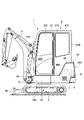
図1において、小型の油圧ショベル1は、キャブ仕様のミニショベルとして構成されている。この小型の油圧ショベル1は、自走可能な下部走行体2と、前記下部走行体2上に旋回可能に搭載された上部旋回体3と、前記上部旋回体3の前,後方向の前側に俯仰動可能に設けられ土砂の掘削作業等を行うフロント装置4とにより構成されている。
In FIG. 1, a small hydraulic excavator 1 is configured as a cab specification mini excavator. This small hydraulic excavator 1 includes a self-propelled lower
ここで、小型の油圧ショベル1は、建物の内部の解体作業、街路地等の狭い場所での掘削作業に用いられるため、例えば機械重量が0.7〜8トン程度までに抑えられている。本実施の形態による油圧ショベル1としては、ミニショベルの中でも、機械重量が2トン以下となる超小型のキャブ仕様の油圧ショベルが例示されている。その構造上の特徴としては、下部走行体2と上部旋回体3と後述するキャブ21のそれぞれの幅寸法がほぼ同じ寸法に設定されている。
Here, since the small hydraulic excavator 1 is used for dismantling work inside a building or excavation work in a narrow place such as a street, the machine weight is suppressed to about 0.7 to 8 tons, for example. As the hydraulic excavator 1 according to the present embodiment, an ultra-compact cab-type hydraulic excavator having a machine weight of 2 tons or less is exemplified among mini excavators. As a structural feature, the width of each of the lower traveling
即ち、図2に示すように、上部旋回体3では、後述の外装カバー23を構成するエンジンカバー部位25の左側面カバー25Aとキャブ21の左パネル21Cとがほぼ同一平面をなしている。同様に、図3に示すように、エンジンカバー部位25の右側面カバー25Bとキャブ21の右パネル21Dとがほぼ同一平面をなしている。
That is, as shown in FIG. 2, in the
このため、超小型の油圧ショベル1は、旋回フレーム5上に各種の搭載機器を配置するためのスペースが狭く、燃料タンク34、作動油タンク35の上側に座席17が配置される構造となっている。この上で、上部旋回体3では、旋回フレーム5を前,後方向に長尺に形成することにより、オペレータの居住スペースを確保し、キャブ21を旋回フレーム5上に搭載できるようにしている。
For this reason, the ultra-small hydraulic excavator 1 has a structure in which a space for arranging various mounted devices on the revolving
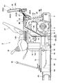
図1ないし図4に示すように、上部旋回体3は、後述の旋回フレーム5、カウンタウエイト6、エンジン7、油圧ポンプ8、サポート部材9、仕切部材11、台座部材14、足置き部材16、キャブ21、外装カバー23、シール取付部30、シール部材31を含んで構成されている。
As shown in FIGS. 1 to 4, the
旋回フレーム5は、下部走行体2上に旋回可能に設けられ、上部旋回体3のベースを構成している。図6ないし図10に示すように、旋回フレーム5は、厚肉な鋼板等を用いて前,後方向に延びる長方形状に形成された底板5Aと、前記底板5A上に前,後方向に延びるように立設された左縦板5B,右縦板5Cとを含む支持構造体をなしている。
The turning
左,右の縦板5B,5Cの前端部には、支持ブラケット5Dが設けられ、この支持ブラケット5Dには、フロント装置4が左,右方向に揺動可能に支持されている。左縦板5Bの後端部には、左後ブラケット5Eが設けられ、この左後ブラケット5Eには、後述するサポート部材9の左後脚部9Cが取付けられている。一方、右縦板5Cの後端部には、右後ブラケット5Fが設けられ、この右後ブラケット5Fには、サポート部材9の右後脚部9Dが取付けられている。底板5Aの前,後方向の中間部には、左縦板5Bの前,後方向の中間部を横切って左,右方向に延びる横板5Gが立設されている。横板5Gは、右縦板5Cから左縦板5Bを超えて底板5Aの左端部まで延在している。
A
横板5Gの左端部は、左前ブラケット5Hとなり、この左前ブラケット5Hには、サポート部材9の左前脚部9Aが取付けられている。底板5Aのうち横板5Gの延長線上に位置する右端部には、底板5Aから上方に立上がって右前ブラケット5Jが設けられている。この右前ブラケット5Jには、サポート部材9の右前脚部9Bが取付けられている。
The left end of the
底板5Aの左端部における前,後方向の中間部には、逆J字型に折曲げられた板体からなる左台座支持部材5Kが、底板5Aから上方に延びて設けられている。左縦板5Bの外面のうち左台座支持部材5Kと左,右方向で対向する部位には、上,下方向に延びる棒状体からなる右台座支持部材5Lが設けられている。これら左,右の台座支持部材5K,5Lは、上部で後述する台座部材14の前側を支持する構成となっている。
A left
さらに、底板5Aの左前側の角部には、その上面にめねじ孔5M1を有する左前キャブ支持部材5Mが立設されている。この左前キャブ支持部材5Mは、めねじ孔5M1に弾性部材(図示せず)が螺着され、この弾性部材を介して後述するキャブ21の左前側を弾性的に支持している。
Further, a left front
一方、底板5Aの右前側の角部には、その上面にめねじ孔5N1を有する右前キャブ支持部材5Nが立設されている。この右前キャブ支持部材5Nは、左前キャブ支持部材5Mとほぼ同様に、めねじ孔5N1に弾性部材(図示せず)が螺着され、この弾性部材を介してキャブ21の右前側を弾性的に支持している。
On the other hand, a right front
このように構成された旋回フレーム5は、その前,後方向の長さ寸法(全長寸法)を、下部走行体2よりも大きく設定している。これにより、旋回フレーム5上には、オペレータの居住空間を確保しつつ、後述のキャブ21を搭載することができる。
The revolving
カウンタウエイト6は、旋回フレーム5の後側に取付けられている。このカウンタウエイト6は、フロント装置4との重量バランスをとるもので、例えば鋳造等を用いて成形された重量物として構成されている。ここで、カウンタウエイト6は、旋回フレーム5を前,後方向に長尺に形成したことにより、旋回中心から離れた位置に配置することができる。これにより、カウンタウエイト6は、フロント装置4との重量バランスを保持しつつ、その高さ寸法を低く抑えることができる。図6、図7に示すように、カウンタウエイト6の上面6Aの中央位置には、後述の外装カバー23を構成するエンジンカバー部位25の後面カバー25Cを閉扉状態に保持するためのストライカ6Bが取付けられている。
The
エンジン7は、後述するエンジン室26に配置された原動機を構成している。エンジン7は、油圧ポンプ8を駆動するもので、カウンタウエイト6の前側に位置して旋回フレーム5の後側に左,右方向に延在する横置き状態で搭載されている。
The
エンジン7には、例えば左,右方向の左側に位置して油圧ポンプ8が設けられ、右側には冷却ファン(図示せず)が設けられている。油圧ポンプ8は、エンジン7によって駆動されることにより、下部走行体2、フロント装置4等に設けられた油圧アクチュエータに作動油を供給するものである。また、冷却ファンと対面する位置には、エンジン冷却水、作動油等を冷却するための熱交換装置(図示せず)が設けられている。なお、原動機としては、エンジンにアシスト用の電動モータを設けたハイブリッド式の原動機を用いることもでき、電動モータだけを原動機として用いることもできる。
The
サポート部材9は、エンジン7を跨ぐように旋回フレーム5上に設けられている。サポート部材9には、後述の仕切部材11、台座部材14、キャブ21の後側等が取付けられている。ここで、図9、図10に示すように、サポート部材9は、左前脚部9A、右前脚部9B、左後脚部9C、右後脚部9Dおよびこれら各脚部9A,9B,9C,9Dの上端に取付けられた支持ベース9Eを含んで構成されている。
The
旋回フレーム5の左端部に位置する左前脚部9Aは、上側に向けて後方に傾斜して延び、下端が旋回フレーム5の左前ブラケット5Hにボルト止めされている。旋回フレーム5の右端部に位置する右前脚部9Bは、上側に向けて後方に傾斜して延び、下端が旋回フレーム5の右前ブラケット5Jにボルト止めされている。一方、左後脚部9Cは、上,下方向に延びた下端が、旋回フレーム5の左後ブラケット5Eにボルト止めされている。右後脚部9Dは、上,下方向に延びた下端が、旋回フレーム5の右後ブラケット5Fにボルト止めされている。
The left
支持ベース9Eは、各脚部9A,9B,9C,9Dの上端に固定されている。支持ベース9Eは、左,右方向に延びる強度部材として形成されている。ここで、支持ベース9Eには、左,右方向の両側に位置して2個のボルト挿通孔9E1が設けられている。このボルト挿通孔9E1には、後述の弾性支持体10の下側部位がボルト止めされている。これにより、支持ベース9Eは、弾性支持体10を介してキャブ21の後側を支持している。
The
左前脚部9Aの上側には、アングル材等からなる左支持部材9Fが前方に向けて突設されている。右前脚部9Bの上,下方向の中間部には、アングル材等からなる右支持部材9Gが左方に向けて突設されている。これら左,右の支持部材9F,9Gには、仕切部材11と台座部材14が取付けられている。
On the upper side of the left
弾性支持体10は、サポート部材9の支持ベース9Eの左,右両側に取付けられている(図4、図8中に左側のみ図示)。弾性支持体10は、弾性を有する円柱状のゴム材を主体とし、上,下位置にねじ止め可能な構造を有している。具体的には、弾性支持体10は、その下側部位がサポート部材9を構成する支持ベース9Eのボルト挿通孔9E1にボルト止めされ、上側部位がキャブ21を構成する後取付板21Hのボルト挿通孔21H1にボルト止めされている。これにより、弾性支持体10は、キャブ21の後側をサポート部材9上に弾性的に支持することができる。
The elastic supports 10 are attached to both the left and right sides of the
次に、旋回フレーム5上に設けられた本実施の形態の特徴部分となる仕切部材11の構成について述べる。
Next, the structure of the
図6、図7に示すように、仕切部材11は、旋回フレーム5とサポート部材9の支持ベース9Eとの間に支持され、エンジン7の前側と上側を覆うものである。これにより、仕切部材11は、エンジン室26とエンジン室26の前側、即ち、後述の運転室22とを仕切っている。即ち、仕切部材11は、エンジン7の前側を覆う前面板部12と、エンジン7の上側を覆う上面板部13とを備えた板状体から構成されている。
As shown in FIGS. 6 and 7, the
ここで、仕切部材11は、旋回フレーム5の全幅寸法と同等な幅寸法をもって形成されている。これにより、仕切部材11がエンジン室26(エンジン7)と運転室22とを仕切ることにより、エンジン7が発生する熱や動作音が運転室22側に伝わらないように遮断することができる。しかも、エンジン室26と運転室22とを1枚の仕切部材11で仕切った構成では、仕切部材11の周囲を後述の外装カバー23で取り囲むだけでエンジン室26を外部に対して密閉することができる。
Here, the
前面板部12は、旋回フレーム5の横板5Gから上側に延びた垂直板12Aと、前記垂直板12Aの上端から斜め後側に延びた傾斜板12Bと、前記傾斜板12Bの左側に位置して小さなステップ状に形成された左支持板12Cと、前記傾斜板12Bの右側に位置して左支持板12Cよりも大きなステップ状に形成された右支持板12Dと、前記垂直板12Aと前記傾斜板12Bとに亘って形成された側面板12Eと、前記側面板12Eの後端縁から屈曲して左方向に延び前記垂直板12Aの下側部分に繋がった左端縁板12Fと、前記右支持板12Dの右端部から下向きに延びた右端縁板12Gとにより構成されている。
The
前記左支持板12C、右支持板12Dには、後述のボルト15を挿通するためのボルト挿通孔12Hがそれぞれ設けられている。左端縁板12Fは、サポート部材9の左前脚部9Aに対面し、右端縁板12Gは、サポート部材9の右前脚部9Bに対面している。さらに、左端縁板12Fの縁部は、後述の左縁部27の一部となり、右端縁板12Gの縁部は、後述の右縁部28の一部となっている。
The
上面板部13は、前面板部12の傾斜板12B、右支持板12Dの上端から後向きに延びた略四角形状の水平板体として形成されている。これにより、上面板部13は、エンジン7の上側を覆っている。上面板部13の左,右両側には、サポート部材9の支持ベース9Eに取付けられた弾性支持体10を挿通するための支持体挿通孔13Aが設けられている。上面板部13の左端縁板13Bの縁部は、後述の左縁部27の一部となり、右端縁板13Cの縁部は、後述の右縁部28の一部となっている。さらに、上面板部13の後端縁板13Dの縁部は、後述の後縁部29となっている。
The
このように構成された仕切部材11は、前面板部12の垂直板12Aの下部が旋回フレーム5の横板5Gにボルト止めされ、上面板部13が旋回フレーム5の支持ベース9Eにボルト止めされている。この上で、前面板部12の左支持板12Cは、サポート部材9の左支持部材9F上に載置され、台座部材14と共に左支持部材9Fに取付けられている。また、右支持板12Dは、サポート部材9の右支持部材9G上に載置され、台座部材14と共に右支持部材9Gに取付けられている。
In the
台座部材14は、仕切部材11の前側に位置して旋回フレーム5と仕切部材11の前面板部12との間に設けられている。台座部材14上には、後述の座席17が取付けられる。台座部材14は、その下側に後述の燃料タンク34と作動油タンク35とを収容するための空間部を有している。これにより、超小型の油圧ショベル1であっても、2個のタンク34,35を台座部材14下の狭い空間に配置できるから、オペレータには、広い居住空間を提供することができる。
The
台座部材14は、前側に位置して旋回フレーム5に立設された前面板14Aと、前面板14Aの上部から後側に延びた平板状の座席取付板14Bとを含んで構成されている。座席取付板14Bの後部には、左,右の角部に位置してボルト挿通孔14Cが設けられている。
The
台座部材14は、仕切部材11の前側に並べて配置され、前面板14Aの下側が旋回フレーム5の左,右の台座支持部材5K,5Lに取付けられている。一方、座席取付板14Bの後側は、各ボルト挿通孔14Cに挿通されたボルト15を、仕切部材11を構成する前面板部12のボルト挿通孔12Hに挿通し、サポート部材9の各支持部材9F,9Gに螺着することにより、仕切部材11と一緒にサポート部材9に取付けられている。
The
足置き部材16は、台座部材14の前側に位置して旋回フレーム5に設けられている。足置き部材16は、座席17に着座したオペレータが足を置くスペースであり、キャブ21内の床板を形成している。足置き部材16の前側には、後述の走行用操作レバー・ペダル20等が配設されている。
The
図4、図8等に示すように、座席17は、台座部材14の座席取付板14B上に設けられている。この座席17は、オペレータが着座する運転席を構成している。座席17の左,右両側には、左作業用操作レバー18と右作業用操作レバー19とが設けられている。これらの作業用操作レバー18,19は、オペレータによって手動操作されることにより、フロント装置4等を動作させるものである。さらに、座席17の前方となる足置き部材16の前側位置には、走行用操作レバー・ペダル20が設けられている。走行用操作レバー・ペダル20は、オペレータによって手動操作または足踏み操作されることにより、下部走行体2を走行させるものである。
As shown in FIGS. 4 and 8, the
キャブ21は、座席17等を覆うように、仕切部材11、台座部材14および足置き部材16の上側に設けられている。キャブ21は、前パネル21A、後パネル21B、左パネル21C、右パネル21Dおよび上パネル21Eによってボックス状に形成されている。左パネル21Cには、乗降するときに開閉されるドア21Fが回動可能に取付けられている。
The
図5に示すように、キャブ21の前パネル21Aの下部には、前パネル21Aに沿って左,右方向に延びた前取付板21Gが設けられている。この前取付板21Gには、旋回フレーム5を構成する各前キャブ支持部材5M,5Nのめねじ孔5M1,5N1に対応する両側位置にボルト挿通孔21G1が設けられている。前取付板21Gは、各ボルト挿通孔21G1に挿通したボルト(図示せず)を、旋回フレーム5の各前キャブ支持部材5M,5Nに取付けられた弾性部材の上側部位に螺着することにより、旋回フレーム5の前部に弾性的に支持されている。
As shown in FIG. 5, a
一方、キャブ21の後パネル21Bの下部には、後パネル21Bに沿って左,右方向に延びた後取付板21Hが設けられている。この後取付板21Hには、サポート部材9を構成する支持ベース9Eの各ボルト挿通孔9E1に対応する両側位置にボルト挿通孔21H1が設けられている。後取付板21Hは、各ボルト挿通孔21H1に挿通したボルト(図示せず)を、弾性支持体10の上側部位に螺着することにより、サポート部材9に弾性的に支持されている。
On the other hand, a
ここで、旋回フレーム5は、前,後方向に長尺に形成されているから、この旋回フレーム5上に搭載されるキャブ21も、前,後方向に長く形成することができる。これにより、超小型な油圧ショベル1においても、十分な居住空間を有したキャブ21を上部旋回体3に配設することができる。しかも、キャブ21の幅寸法は、旋回フレーム5の幅寸法とほぼ同じ寸法に設定されている。従って、旋回フレーム5上の限られた設置スペースに対し、キャブ21として最大限の幅寸法を得ることができ、この点においても、居住空間を広くすることができる。このキャブ21内の居住空間がオペレータが乗り込む運転室22となっている。
Here, since the revolving
外装カバー23は、旋回フレーム5を取り囲むように配置され、旋回フレーム5の底板5Aの周縁から立上った複数枚の板体により構成されている。外装カバー23は、キャブ21の前下側部分である足置き部材16の周囲を覆う前カバー部位24と、前記キャブ21の後下側部分であるエンジン室26の左側、右側および後側を覆うエンジンカバー部位25とにより構成されている。
The
前カバー部位24は、旋回フレーム5と足置き部材16とに亘って設けられている。前カバー部位24は、足置き部材16の左辺に沿って前,後方向に延び、前側が右側に屈曲した左スカートカバー24Aと、足置き部材16の右辺に沿って前,後方向に延び、前側が左側に屈曲した右スカートカバー24Bとを含んで構成されている。
The
原動機カバー部位としてのエンジンカバー部位25は、エンジン室26の左側を覆う左側面カバー25Aと、前記エンジン室26の右側を覆う右側面カバー25Bと、前記左側面カバー25Aと前記右側面カバー25Bとに挟まれてエンジン室26の後側を覆う後面カバー25Cとを含んで構成されている。
The
エンジンカバー部位25の左側面カバー25Aと右側面カバー25Bと後面カバー25Cおよび前述した前カバー部位24の左スカートカバー24Aと右スカートカバー24Bは、旋回フレーム5、サポート部材9等の構造物に対しボルト等を用いて着脱可能に取付けられている。
The
左側面カバー25Aは、旋回フレーム5の底板5A、カウンタウエイト6とキャブ21との間に配設されている。この左側面カバー25Aは、旋回フレーム5の左側から後側に回り込むように屈曲した板状体として形成されている。ここで、左側面カバー25Aの上側の外端25A1は、仕切部材11を構成する前面板部12の左端縁板12Fに沿って斜め上側に向けて延びつつ、上面板部13の左端縁板13Bの位置で左端縁板13Bに沿って水平方向に延びている。
The
左側面カバー25Aの外端25A1の内側(エンジン室26側)には、後述するシール部材31に対面してシール筒33に密着されるシール面25A2(点線で取り囲まれた内面部位)が設けられている。左側面カバー25Aのシール面25A2は、シール部材31と対面したときに隙間なく密着できるようになだらかな面として形成されている。具体的には、シール面25A2は、長尺に形成された1本のシール部材31のうち、後述の左縁部27に沿って設けられた左側部位に当接するものである。
Inside the outer end 25A1 of the
ここで、シール面25A2のなだらかな面とは、シール部材31のシール筒33との間で隙間を生じるような段差(曲がり)がほぼ存在しない形状である。即ち、シール面25A2のなだらかな面には、ほぼ平坦な面以外にも、シール筒33が隙間なく密着できる緩やかな湾曲面も含むものである。さらに、左側面カバー25Aは、例えば旋回フレーム5、サポート部材9等に対し着脱可能にボルト止めされている。
Here, the gentle surface of the
右側面カバー25Bは、左側面カバー25Aとエンジン室26を挟んで左,右方向で対面し、旋回フレーム5の底板5A、カウンタウエイト6とキャブ21との間に配設されている。この右側面カバー25Bは、左側面カバー25Aと対称形状をなすように、旋回フレーム5の右側から後側に回り込むように屈曲した板状体として形成されている。ここで、右側面カバー25Bの上側の外端25B1は、仕切部材11を構成する前面板部12の右端縁板12Gに沿って上側に延びつつ、上面板部13の右端縁板13Cの位置で右端縁板13Cに沿って水平方向に延びている。
The
右側面カバー25Bの外端25B1の内側(エンジン室26側)には、後述するシール部材31に対面してシール筒33に密着されるシール面25B2(点線で取り囲まれた内面部位)が設けられている。右側面カバー25Bのシール面25B2は、左側面カバー25Aのシール面25A2と同様に、シール筒33と対面したときに隙間なく密着できるように段差の無いなだらかな面として形成されている。シール面25B2は、1本のシール部材31のうち、後述の右縁部28に沿って設けられた右側部位に当接するものである。さらに、右側面カバー25Bは、その前側部分が例えばサポート部材9等に対し左,右方向に開閉可能に取付けられている。
Inside the outer end 25B1 of the
後面カバー25Cは、左側面カバー25Aと右側面カバー25Bとカウンタウエイト6の上面6Aとキャブ21の後パネル21Bとに囲まれた長方形状の板状体として形成されている。後面カバー25Cの上側の外端25C1は、仕切部材11を構成する上面板部13の後端縁板13Dの位置で後端縁板13Dに沿って左,右方向(水平方向)に延びている。
The
後面カバー25Cの外端25C1の内側(エンジン室26側)には、シール部材31に対面してシール筒33に密着されるシール面25C2(点線で取り囲まれた内面部位)が設けられている。後面カバー25Cのシール面25C2は、各シール面25A2,25B2と同様に、シール筒33と対面したときに隙間なく密着できるように段差の無いなだらかな面として形成されている。シール面25C2は、1本のシール部材31のうち、後述の後縁部29に沿って設けられた後側部位に当接するものである。
Inside the outer end 25C1 of the
さらに、図6に示すように、後面カバー25Cは、リンク機構25C3を介してサポート部材9に取付けられている。これにより、図7に示すように、リンク機構25C3を支点として後面カバー25Cを上側に持ち上げることにより、後面カバー25Cを開くことができる。また、後面カバー25Cの下側位置には、キャッチ25C4が設けられ、このキャッチ25C4は、カウンタウエイト6側のストライカ6Bに係合することにより、後面カバー25Cを閉扉状態に保持することができる。
Further, as shown in FIG. 6, the
エンジン室26は、旋回フレーム5の底板5A、仕切部材11および外装カバー23のエンジンカバー部位25によって囲まれている。このエンジン室26は、原動機室を構成するもので、エンジン7、油圧ポンプ8等が収容されている。
The
次に、仕切部材11の一部として設けられた左縁部27、右縁部28および後縁部29の構成について述べる。
Next, the structure of the
左縁部27は、仕切部材11の左側の端縁部として形成されている。左縁部27は、垂直板12Aの左端部、仕切部材11を構成する前面板部12の左端縁板12Fおよび上面板部13の左端縁板13Bに亘り、これらの縁部として形成されている。
The
右縁部28は、左縁部27と左,右方向の反対側となる仕切部材11の右側の端縁部として形成されている。右縁部28は、左縁部27とほぼ同様に、仕切部材11を構成する前面板部12の右端縁板12Gと上面板部13の右端縁板13Cとに亘り、これらの縁部として形成されている。
The
さらに、後縁部29は、左縁部27と右縁部28との間に位置して仕切部材11の後側の端縁部として形成されている。後縁部29は、仕切部材11を構成する上面板部13の後端縁板13Dの縁部として形成されている。例えば、後縁部29は、左,右方向の中央部分が後側に突出するように緩やかに湾曲している。
Further, the
次に、仕切部材11と外装カバー23のエンジンカバー部位25との間をシールするためのシール取付部30、シール部材31等について説明する。
Next, the
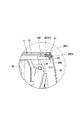
シール取付部30は、仕切部材11の一部として形成されている。シール取付部30は、左縁部27、右縁部28および後縁部29の端縁を突出させることにより形成されている。シール取付部30は、左縁部27の下端位置から後縁部29を経由して右縁部28の下端位置までほぼ連続する所定幅の取付代、即ち、図14中にドット模様で示す狭幅帯状の範囲となっている。このシール取付部30の所定幅とは、後述するシール部材31の取付部32によって挟まれる範囲となっている。この場合、シール取付部30は、シール部材31の取付部32が確実に挟むことができるように、折れや歪みの少ない平坦状に形成されている。
The
シール部材31は、仕切部材11の周縁部に設けられている。シール部材31は、仕切部材11の左縁部27、右縁部28および後縁部29に沿って連続して延びている。シール部材31は、左縁部27、右縁部28および後縁部29に設けたシール取付部30に対し連続して取付けられる単一部材として構成されている。
The
図13に示すように、シール部材31は、シール取付部30を挟む断面U字状の取付部32と、取付部32の先端部に設けられた円筒状のシール筒33とにより構成されている。シール部材31は、ウエザストリップと呼ばれるもので、弾性を有する樹脂材料(例えば、発泡性のウレタン樹脂材料等)により形成されている。上述したシール部材31の構成は、一般的に用いられるものを一例として示したものであり、これ以外の形状、例えば中空なシール筒に代えて中実なシール部とすることもできる。
As shown in FIG. 13, the
シール部材31は、例えば押出し加工によって長尺に形成されたロール状の製品を引き出して所望の長さ寸法に切断することにより、1本のシール部材として形成されている。そして、シール部材31は、その取付部32をシール取付部30に取付けることにより、仕切部材11の周囲に一体的に配設されている。この場合、1本のシール部材31は、仕切部材11に対して容易に取付けることができる。
The
仕切部材11のシール取付部30に取付けられたシール部材31は、左縁部27に対応する位置が左シール部31Aとなり、右縁部28に対応する位置が右シール部31Bとなり、後縁部29に対応する位置が後シール部31Cとなっている。なお、図14では、仕切部材11から分離したシール部材31を、取付構造を容易に理解できるように、シール取付部30に対応した形状に保持した状態で示している。しかし、分離されたシール部材31は、実際には、自由に変形可能な1本の紐状体ないし帯状体となる。
The
仕切部材11に取付けられたシール部材31は、シール筒33に、エンジンカバー部位25の左側面カバー25Aのシール面25A2、右側面カバー25Bのシール面25B2および後面カバー25Cのシール面25C2が押付けられる。これにより、シール部材31は、シール筒33が変形して各シール面25A2,25B2,25C2に密着することにより、仕切部材11とエンジンカバー部位25との間をシールすることができる。このときに、1本のシール部材31は、エンジンカバー部位25の左側面カバー25Aと後面カバー25Cとの間、右側面カバー25Bと後面カバー25Cとの間にも存在している。従って、シール部材31は、各カバー25A,25B,25C間からの異物、雨水等の進入、エンジン7による熱気の漏出を抑制することができる。
The
なお、燃料タンク34は、旋回フレーム5の前,後方向の中間部に位置して底板5Aの左側寄りに搭載されている。燃料タンク34は、エンジン7に供給される燃料を貯えるものである。
The
作動油タンク35は、燃料タンク34と左,右方向の反対側となる底板5Aの右側寄りに搭載されている。作動油タンク35は、油圧ポンプ8に供給される作動油を貯えるものである。
The
ここで、燃料タンク34と作動油タンク35は、台座部材14の下側に収められている。各タンク34,35を台座部材14の下側に収めた構成では、キャブ21は、各タンク34,35を避けて配設する必要がなくなるから、キャブ21を旋回フレーム5の全幅に亘って形成することができる。従って、運転室22とエンジン室26とは、仕切部材11だけで仕切ることができる。これにより、仕切部材11と外装カバー23のエンジンカバー部位25との間をシール部材31によってシールするだけで、外部の異物、塵埃、雨水等がエンジン室26内に入り込まないようにすることができ、また、エンジン室26内の熱気、動作音がオペレータ側に伝わらないようにすることができる。
Here, the
排土板36は、下部走行体2の前側に左,右方向に延びると共に、上,下方向に回動可能に設けられている。この排土板36は、例えば、土砂の排出、整地等の排土作業、除雪作業等を行うものである。
The
本実施の形態による油圧ショベル1は上述の如き構成を有するもので、次に、この油圧ショベル1の動作について説明する。 The hydraulic excavator 1 according to the present embodiment has the above-described configuration. Next, the operation of the hydraulic excavator 1 will be described.
まず、超小型の油圧ショベル1は、トラックの荷台に積載された状態で作業現場まで搬送される。油圧ショベル1が作業現場に搬送されると、オペレータは、キャブ21内に乗り込んで座席17に着座する。この状態で走行用操作レバー・ペダル20を操作することにより、下部走行体2を駆動して油圧ショベル1を前進または後退させることができる。一方、座席17に着座したオペレータは、左,右の作業用操作レバー18,19を操作することにより、フロント装置4等を動作させて建物内部の解体作業、狭い街路地等での側溝掘り作業を行うことができる。
First, the ultra-small hydraulic excavator 1 is transported to the work site in a state of being loaded on a truck bed. When the excavator 1 is transported to the work site, the operator gets into the
油圧ショベル1の稼働時には、外部の異物、塵埃、雨水等がエンジン室26内に入り込む虞がある。一方で、エンジン室26内では、エンジン7が熱や動作音を発生するから、このエンジン7による熱気等が漏れ出てオペレータ側に伝わる虞がある。
When the excavator 1 is in operation, there is a risk that external foreign matter, dust, rainwater, etc. will enter the
然るに、本実施の形態によれば、仕切部材11は、左,右方向の左側に位置して前面板部12から上面板部13に亘る左縁部27と、前記左縁部27と左,右方向の反対側に位置して前記前面板部12から前記上面板部13に亘る右縁部28と、前記左縁部27と前記右縁部28との間に位置して前記上面板部13の後側の後縁部29とを有している。前記仕切部材11には、前記左縁部27、右縁部28および後縁部29に沿って連続して延びたシール部材31が設けられている。この上で、外装カバー23を構成するエンジンカバー部位25の各カバー25A,25B,25Cには、前記シール部材31に対面して前記シール部材31に密着されるシール面25A2,25B2,25C2が設けられている。
However, according to the present embodiment, the
従って、シール部材31は、仕切部材11とエンジンカバー部位25との間をシールすることができる。これにより、シール部材31は、外部の異物、塵埃、雨水等がエンジン室26内に入り込むのを抑制することができる。一方で、エンジン室26内のエンジン7が熱や動作音を発生しても、このときの熱気や動作音は、シール部材31によってエンジン室26内に封じ込めることができる。
Therefore, the
ここで、シール部材31は、仕切部材11の左縁部27、右縁部28および後縁部29に設けたシール取付部30に沿って連続して延びる1本のシール部材として形成している。これにより、1本のシール部材31は、仕切部材11に対して容易に取付けることができる。しかも、1本のシール部材31は、左側面カバー25Aと後面カバー25Cとの間、右側面カバー25Bと後面カバー25Cとの間にも存在し、シール機能を有することができる。
Here, the
この結果、1本のシール部材31を連続して取付けるという簡単な構成、少ない部品点数で、仕切部材11と外装カバー23のエンジンカバー部位25との間をシールすることができる。これにより、超小型の油圧ショベル1に対する信頼性の向上、製造コストの低減等を図ることができる。
As a result, it is possible to seal between the
また、エンジンカバー部位25の左側面カバー25A,右側面カバー25B,後面カバー25Cに設けられたシール面25A2,25B2,25C2は、シール部材31と対面する部位がなだらかな面として形成されている。これにより、シール部材31は、そのシール筒33を各シール面25A2,25B2,25C2に対して確実に密着させることができ、シール性(気密性、持続性等)を高めることができる。
Further, the seal surfaces 25A2, 25B2, and 25C2 provided on the
仕切部材11の左縁部27、右縁部28および後縁部29には、端縁を突出させることにより形成されたシール取付部30を有している。これにより、このシール取付部30を利用して単一部材からなるシール部材31を容易に取付けることができる。
The
1 小型の油圧ショベル
2 下部走行体
3 上部旋回体
4 フロント装置
5 旋回フレーム
6 カウンタウエイト
7 エンジン(原動機)
8 油圧ポンプ
9 サポート部材
9A〜9D 脚部
9E 支持ベース
11 仕切部材
12 前面板部
13 上面板部
14 台座部材
16 足置き部材
17 座席
21 キャブ
22 運転室
23 外装カバー
24 前カバー部位
25 エンジンカバー部位(原動機カバー部位)
25A 左側面カバー
25A1,25B1,25C1 外端
25A2,25B2,25C2 シール面
25B 右側面カバー
25C 後面カバー
26 エンジン室(原動機室)
27 左縁部
28 右縁部
29 後縁部
30 シール取付部
31 シール部材
DESCRIPTION OF SYMBOLS 1 Small
DESCRIPTION OF
25A Left side cover 25A1, 25B1, 25C1 Outer end 25A2, 25B2,
27
Claims (1)
前記上部旋回体は、
支持構造体をなす旋回フレームと、
前記旋回フレームの後側に搭載された原動機と、
前記原動機を跨ぐように前記旋回フレーム上に設けられた脚部および前記脚部の上端に設けられた支持ベースからなるサポート部材と、
前記原動機の前側を覆う前面板部と前記前面板部の上端から後方に延びて前記原動機の上側を覆う上面板部とを備え、前記前面板部が前記旋回フレームに取付けられると共に前記上面板部が前記サポート部材の支持ベースに取付けられ、前記原動機が配置された原動機室と前記原動機室の前側とを仕切っている仕切部材と、
前記仕切部材の前側に位置して前記旋回フレームと前記仕切部材の前面板部との間に設けられ座席が取付けられる台座部材と、
前記台座部材の前側に位置して前記旋回フレームに設けられオペレータの足が置かれる足置き部材と、
前端が前記旋回フレームの前側に支持されると共に後端が前記サポート部材の支持ベースに支持され、前記仕切部材、台座部材および足置き部材の上側を覆って、内部に運転室を画成しているキャブと、
前記キャブの前下側部分である前記足置き部材の周囲を覆う前カバー部位と前記キャブの後下側部分である前記原動機室の左側、右側および後側を覆う原動機カバー部位とからなる外装カバーとを備えてなる小型の油圧ショベルにおいて、
前記仕切部材は、左,右方向の左側に位置して前記前面板部から前記上面板部に亘る左縁部と、前記左縁部と左,右方向の反対側に位置して前記前面板部から前記上面板部に亘る右縁部と、前記左縁部と前記右縁部との間に位置して前記上面板部の後側の後縁部とを有しており、
前記仕切部材の前記左縁部、前記右縁部および前記後縁部には、端縁を突出させることにより形成されたシール取付部が設けられており、
前記シール取付部には、前記左縁部に対応する左シール部、右縁部に対応する右シール部および後縁部に対応する後シール部からなる1本のシール部材が連続して取付けられており、
前記シール部材は、前記シール取付部を挟む断面U字状の取付部と、前記取付部の先端側に設けられた円筒状のシール筒とにより自由に変形可能な1本の紐状体として構成されており、
前記外装カバーの前記原動機カバー部位には、前記シール部材に対面して前記シール筒に密着することにより、前記仕切部材と前記原動機カバー部位との間をシールするシール面が設けられ、
前記外装カバーの前記原動機カバー部位は、前記原動機室の左側を覆う左側面カバーと、前記原動機室の右側を覆う右側面カバーと、前記左側面カバーと前記右側面カバーとに挟まれて前記原動機室の後側を覆う後面カバーとを含んで構成されており、
前記原動機カバー部位の前記左側面カバー、右側面カバーおよび後面カバーの外端には、前記シール筒と当接する前記シール面がそれぞれ設けられていることを特徴とする小型の油圧ショベル。 A self-propelled lower traveling body, an upper revolving body mounted on the lower traveling body so as to be able to swivel, and a front device provided so as to be able to move up and down on the front side in the front and rear directions of the upper revolving body. ,
The upper swing body is
A swivel frame forming a support structure;
A prime mover mounted on the rear side of the swivel frame;
A support member comprising a leg portion provided on the revolving frame so as to straddle the prime mover and a support base provided at an upper end of the leg portion;
A front plate that covers the front side of the prime mover and an upper plate that extends rearward from the upper end of the front plate and covers the upper side of the prime mover, and the front plate is attached to the revolving frame and the upper plate Is attached to a support base of the support member, and a partition member that partitions a prime mover chamber in which the prime mover is disposed and a front side of the prime mover chamber,
A pedestal member that is provided between the revolving frame and the front plate portion of the partition member and is mounted on the front side of the partition member;
A footrest member provided on the swivel frame and positioned on the front side of the pedestal member, on which an operator's foot is placed;
The front end is supported on the front side of the revolving frame and the rear end is supported on the support base of the support member, covers the upper side of the partition member, the pedestal member and the footrest member, and defines a cab inside. With the cab,
An exterior cover comprising a front cover part that covers the periphery of the footrest member that is the front lower part of the cab and a motor cover part that covers the left side, the right side, and the rear side of the motor room that is the rear lower part of the cab In a small hydraulic excavator comprising
The partition member is located on the left side in the left and right directions and extends from the front plate part to the top plate part, and on the opposite side of the left edge and the left and right directions. A right edge extending from the upper surface plate portion to the upper edge plate portion, and a rear edge of the upper surface plate portion located between the left edge portion and the right edge portion,
The left edge part, the right edge part and the rear edge part of the partition member are provided with seal attaching parts formed by projecting end edges,
Wherein the seal mounting portion, the left sealing portion corresponding to the left edge, one seal member made of the sealing portion is mounted in succession after corresponding to the right sealing and trailing edges corresponding to the right edge And
The seal member is configured as a single string-like body that can be freely deformed by an attachment portion having a U-shaped cross section sandwiching the seal attachment portion and a cylindrical seal cylinder provided on the distal end side of the attachment portion. Has been
The motor cover part of the outer cover is provided with a seal surface that seals between the partition member and the motor cover part by facing the seal member and closely contacting the seal cylinder ,
The prime mover cover portion of the exterior cover is sandwiched between a left side cover covering the left side of the prime mover chamber, a right side cover covering the right side of the prime mover chamber, the left side cover and the right side cover, and the prime mover. A rear cover covering the rear side of the chamber,
A small-sized hydraulic excavator characterized in that the seal surfaces that come into contact with the seal cylinder are respectively provided at outer ends of the left side cover, right side cover, and rear cover of the prime mover cover part .
Priority Applications (2)
| Application Number | Priority Date | Filing Date | Title |
|---|---|---|---|
| JP2016064096A JP6585534B2 (en) | 2016-03-28 | 2016-03-28 | Small excavator |
| PCT/JP2016/083391 WO2017168818A1 (en) | 2016-03-28 | 2016-11-10 | Compact hydraulic shovel |
Applications Claiming Priority (1)
| Application Number | Priority Date | Filing Date | Title |
|---|---|---|---|
| JP2016064096A JP6585534B2 (en) | 2016-03-28 | 2016-03-28 | Small excavator |
Publications (3)
| Publication Number | Publication Date |
|---|---|
| JP2017179738A JP2017179738A (en) | 2017-10-05 |
| JP2017179738A5 JP2017179738A5 (en) | 2018-11-08 |
| JP6585534B2 true JP6585534B2 (en) | 2019-10-02 |
Family
ID=59963804
Family Applications (1)
| Application Number | Title | Priority Date | Filing Date |
|---|---|---|---|
| JP2016064096A Active JP6585534B2 (en) | 2016-03-28 | 2016-03-28 | Small excavator |
Country Status (2)
| Country | Link |
|---|---|
| JP (1) | JP6585534B2 (en) |
| WO (1) | WO2017168818A1 (en) |
Families Citing this family (2)
| Publication number | Priority date | Publication date | Assignee | Title |
|---|---|---|---|---|
| JP7191782B2 (en) * | 2019-06-26 | 2022-12-19 | 株式会社クボタ | work machine |
| CN115198834A (en) * | 2022-07-29 | 2022-10-18 | 天津移山工程机械有限公司 | Double-seat box structure of cab and crawler-type bulldozer |
Family Cites Families (6)
| Publication number | Priority date | Publication date | Assignee | Title |
|---|---|---|---|---|
| JP2000265729A (en) * | 1999-03-18 | 2000-09-26 | Shin Caterpillar Mitsubishi Ltd | Open-close device |
| JP2001140647A (en) * | 1999-11-11 | 2001-05-22 | Hitachi Constr Mach Co Ltd | Construction machine |
| JP4188799B2 (en) * | 2003-10-17 | 2008-11-26 | 日立建機株式会社 | Construction machinery |
| WO2013051609A1 (en) * | 2011-10-05 | 2013-04-11 | 日立建機株式会社 | Construction equipment |
| JP6135439B2 (en) * | 2013-10-09 | 2017-05-31 | 株式会社デンソー | Power converter |
| CN105637151B (en) * | 2015-09-30 | 2021-03-26 | 株式会社小松制作所 | Hydraulic excavator |
-
2016
- 2016-03-28 JP JP2016064096A patent/JP6585534B2/en active Active
- 2016-11-10 WO PCT/JP2016/083391 patent/WO2017168818A1/en active Application Filing
Also Published As
| Publication number | Publication date |
|---|---|
| JP2017179738A (en) | 2017-10-05 |
| WO2017168818A1 (en) | 2017-10-05 |
Similar Documents
| Publication | Publication Date | Title |
|---|---|---|
| US7481289B2 (en) | Swiveling work machine | |
| JP4233595B2 (en) | Work vehicle | |
| JP4814235B2 (en) | Construction machinery cab structure | |
| JP4976594B2 (en) | Construction machinery | |
| JP5691944B2 (en) | Equipment support structure of upper swing body | |
| JP6585534B2 (en) | Small excavator | |
| JP2007120221A (en) | Construction machine | |
| JP4387893B2 (en) | Construction machinery cab | |
| JP2007092278A (en) | Upper structure of backhoe | |
| JP2005119362A (en) | Construction machine | |
| JP4394518B2 (en) | Construction machinery | |
| WO2017163477A1 (en) | Compact hydraulic excavator | |
| JP4468872B2 (en) | Construction machinery | |
| US10267017B2 (en) | Small-sized construction machine | |
| JP4256219B2 (en) | Construction machinery | |
| JP4199173B2 (en) | Swivel construction machine | |
| JP4381364B2 (en) | Backhoe | |
| JP4885787B2 (en) | Construction machinery | |
| JP2005336829A (en) | Revolving frame for construction machine | |
| JP6884732B2 (en) | Remote-controlled small hydraulic excavator | |
| JP4703334B2 (en) | Backhoe | |
| JP6498592B2 (en) | Small construction machinery | |
| JP2007092281A (en) | Backhoe | |
| JP2013237985A (en) | Construction machine | |
| JP2018145597A (en) | Hydraulic shovel |
Legal Events
| Date | Code | Title | Description |
|---|---|---|---|
| A711 | Notification of change in applicant |
Free format text: JAPANESE INTERMEDIATE CODE: A711 Effective date: 20170130 |
|
| A521 | Written amendment |
Free format text: JAPANESE INTERMEDIATE CODE: A523 Effective date: 20180919 |
|
| A621 | Written request for application examination |
Free format text: JAPANESE INTERMEDIATE CODE: A621 Effective date: 20180919 |
|
| A131 | Notification of reasons for refusal |
Free format text: JAPANESE INTERMEDIATE CODE: A131 Effective date: 20190702 |
|
| A521 | Written amendment |
Free format text: JAPANESE INTERMEDIATE CODE: A523 Effective date: 20190830 |
|
| TRDD | Decision of grant or rejection written | ||
| A01 | Written decision to grant a patent or to grant a registration (utility model) |
Free format text: JAPANESE INTERMEDIATE CODE: A01 Effective date: 20190903 |
|
| A61 | First payment of annual fees (during grant procedure) |
Free format text: JAPANESE INTERMEDIATE CODE: A61 Effective date: 20190905 |
|
| R150 | Certificate of patent or registration of utility model |
Ref document number: 6585534 Country of ref document: JP Free format text: JAPANESE INTERMEDIATE CODE: R150 |