JP6577823B2 - Torque fluctuation suppressing device, torque converter, and power transmission device - Google Patents
Torque fluctuation suppressing device, torque converter, and power transmission device Download PDFInfo
- Publication number
- JP6577823B2 JP6577823B2 JP2015208759A JP2015208759A JP6577823B2 JP 6577823 B2 JP6577823 B2 JP 6577823B2 JP 2015208759 A JP2015208759 A JP 2015208759A JP 2015208759 A JP2015208759 A JP 2015208759A JP 6577823 B2 JP6577823 B2 JP 6577823B2
- Authority
- JP
- Japan
- Prior art keywords
- rotating body
- torque
- torque fluctuation
- centrifuge
- suppressing device
- Prior art date
- Legal status (The legal status is an assumption and is not a legal conclusion. Google has not performed a legal analysis and makes no representation as to the accuracy of the status listed.)
- Active
Links
Images


Description
本発明は、トルク変動抑制装置、特に、トルクが入力される回転体のトルク変動を抑制するためのトルク変動抑制装置に関する。また、本発明は、トルク変動抑制装置を備えたトルクコンバータ及び動力伝達装置に関する。 The present invention relates to a torque fluctuation suppressing device, and more particularly to a torque fluctuation suppressing device for suppressing torque fluctuation of a rotating body to which torque is input. The present invention also relates to a torque converter and a power transmission device including a torque fluctuation suppressing device.
例えば、自動車のエンジンとトランスミッションとの間には、ダンパ装置を含むクラッチ装置やトルクコンバータが設けられている。また、トルクコンバータには、燃費低減のために、所定の回転数以上で機械的にトルクを伝達するためのロックアップ装置が設けられている。このロックアップ装置には、複数のトーションスプリングを含むダンパが設けられている。 For example, a clutch device including a damper device and a torque converter are provided between an automobile engine and a transmission. Further, the torque converter is provided with a lockup device for mechanically transmitting torque at a predetermined rotational speed or more in order to reduce fuel consumption. This lockup device is provided with a damper including a plurality of torsion springs.
より詳細には、ロックアップ装置は、一般に、クラッチ部と、複数のトーションスプリングを有するダンパと、を有している。また、クラッチ部は、油圧の作用によってフロントカバーに押し付けられる摩擦部材付きのピストンを有している。そして、ロックアップオンの状態では、トルクは、フロントカバーから摩擦部材を介してピストンに伝達され、さらに複数のトーションスプリングを介して出力側の部材に伝達される。 More specifically, the lockup device generally includes a clutch portion and a damper having a plurality of torsion springs. The clutch portion has a piston with a friction member that is pressed against the front cover by the action of hydraulic pressure. In the lock-up-on state, torque is transmitted from the front cover to the piston via the friction member, and further transmitted to the output side member via the plurality of torsion springs.
このようなロックアップ装置では、複数のトーションスプリングを有するダンパによって、トルク変動(回転速度変動)が抑えられる。 In such a lock-up device, torque fluctuations (rotational speed fluctuations) are suppressed by a damper having a plurality of torsion springs.
また、特許文献1のロックアップ装置では、イナーシャ部材を含むダイナミックダンパ装置を設けることによって、トルク変動を抑えるようにしている。特許文献1のダイナミックダンパ装置は、トーションスプリングを支持するプレートに装着されており、このプレートと相対回転自在な1対のイナーシャリングと、プレートとイナーシャリングとの間に設けられた複数のコイルスプリングと、を有している。
Further, in the lockup device disclosed in
特許文献1を含む従来のダイナミックダンパ装置では、所定の回転数域に発生するトルク変動のピークを抑えることができる。
In the conventional dynamic damper device including
しかし、ダイナミックダンパ装置を構成するイナーシャリング及びコイルスプリングを配置するために、軸方向スペースが必要になる。特許文献1の装置では、ダイナミックダンパ装置はデッドスペースに配置されているので、装置全体を比較的コンパクトにすることができる。しかし、場合によって、ダイナミックダンパ装置を設けることによって、軸方向における装置の大型化を招く場合がある。
However, in order to arrange the inertia ring and the coil spring constituting the dynamic damper device, an axial space is required. In the device of
また、特許文献1を含む従来のダイナミックダンパ装置では、所定の回転数域のトルク変動のピークを抑えることができるが、エンジンの仕様等が変わると、それに伴いイナーシャリングの慣性量及びコイルスプリングのばね定数を変更する必要があり、対応が困難な場合がある。
In addition, in the conventional dynamic damper device including
本発明の課題は、回転部材のトルク変動を抑えるための装置において、装置全体の軸方向スペースを大きくすることなく、比較的広い回転数域においてトルク変動のピークを抑えることができるようにすることにある。 An object of the present invention is to enable a device for suppressing torque fluctuation of a rotating member to suppress a peak of torque fluctuation in a relatively wide rotational speed range without increasing the axial space of the entire apparatus. It is in.
(1)本発明に係るトルク変動抑制装置は、トルクが入力される回転体のトルク変動を抑制するための装置である。トルク変動抑制装置は、質量体と、遠心子と、カム機構と、を備えている。質量体は、回転体とともに回転可能であり、回転体に対して相対回転自在に配置されている。遠心子は、回転体及び質量体の回転による遠心力を受けるように配置されている。カム機構は、遠心子に作用する遠心力を受けて、回転体と質量体との間に回転方向における相対変位が生じたときには、遠心力を、相対変位が小さくなる方向の円周方向力に変換するとともに、回転体に所定の大きさ以上のトルク変動が入力されたときには、回転体に対して質量体を自由に回転させる。 (1) A torque fluctuation suppressing device according to the present invention is a device for suppressing torque fluctuation of a rotating body to which torque is input. The torque fluctuation suppressing device includes a mass body, a centrifuge, and a cam mechanism. The mass body can be rotated together with the rotating body, and is disposed so as to be rotatable relative to the rotating body. The centrifuge is arranged to receive a centrifugal force due to the rotation of the rotating body and the mass body. The cam mechanism receives a centrifugal force acting on the centrifuge, and when a relative displacement in the rotational direction occurs between the rotating body and the mass body, the centrifugal force is converted into a circumferential force in a direction in which the relative displacement is reduced. In addition to the conversion, when a torque fluctuation of a predetermined magnitude or more is input to the rotating body, the mass body is freely rotated with respect to the rotating body.
この装置では、回転体にトルクが入力されると、カム機構の作動によって回転体及び質量体が回転する。回転体に入力されるトルクに変動がない場合は、回転体と質量体との間の回転方向における相対変位はなく、同期して回転する。一方、入力されるトルクに変動がある場合は、質量体は回転体に対して相対回転自在に配置されているために、トルク変動の程度によっては、両者の間に回転方向における相対変位(以下、この変位を「回転位相差」と表現する場合がある)が生じる場合がある。 In this device, when torque is input to the rotating body, the rotating body and the mass body are rotated by the operation of the cam mechanism. When there is no change in the torque input to the rotating body, there is no relative displacement in the rotating direction between the rotating body and the mass body, and the rotor rotates synchronously. On the other hand, when there is a fluctuation in the input torque, the mass body is arranged so as to be relatively rotatable with respect to the rotating body. In some cases, this displacement may be expressed as “rotational phase difference”).
ここで、回転体及び質量体が回転すると、遠心子は遠心力を受ける。そして、カム機構は、この遠心子に作用する遠心力によって、回転体と質量体との間に相対変位が生じたときには、遠心子に作用する遠心力を円周方向力に変換し、この円周方向力によって回転体と質量体の間の相対変位を小さくするように作動する。このようなカム機構の作動によって、トルク変動が抑えられる。また、回転体に所定の大きさ以上のトルク変動が入力されたときには、質量体は、回転体に対して相対変位が生じた方向に自由に回転する。 Here, when the rotating body and the mass body rotate, the centrifuge receives a centrifugal force. The cam mechanism converts the centrifugal force acting on the centrifuge into a circumferential force when a relative displacement occurs between the rotating body and the mass body due to the centrifugal force acting on the centrifuge. It operates to reduce the relative displacement between the rotating body and the mass body by the circumferential force. Torque fluctuation is suppressed by the operation of the cam mechanism. Further, when a torque fluctuation of a predetermined magnitude or more is input to the rotating body, the mass body freely rotates in the direction in which relative displacement occurs with respect to the rotating body.
ここでは、質量体、遠心子、及びカム機構によって装置を構成しているので、これらの部材を回転体に対して径方向に並べて配置することが可能になり、軸方向のスペースを小さくすることが可能になる。また、遠心子に作用する遠心力を、トルク変動を抑えるために利用しているので、回転体の回転数に応じてトルク変動を抑制する特性が変わることになり、またカム機構の仕様を変更することによってもトルク変動を抑制する特性を変えることができ、より広い回転数域におけるトルク変動のピークを抑えることができる。さらに、カム機構は、回転体に所定の大きさ以上のトルク変動が入力されたときには、質量体を相対変位が生じた方向に自由に回転させるので、カム機構に過大な力が作用するのを防止できる。このため、カム機構の強度を適切な強度に設定して、カム機構のコストアップを避け、かつカム機構の損傷を避けることができる。 Here, since the apparatus is constituted by the mass body, the centrifuge, and the cam mechanism, these members can be arranged side by side in the radial direction with respect to the rotating body, and the axial space can be reduced. Is possible. In addition, since the centrifugal force acting on the centrifuge is used to suppress torque fluctuations, the characteristics that suppress torque fluctuations change according to the rotational speed of the rotating body, and the specifications of the cam mechanism are changed. By doing so, it is possible to change the characteristic for suppressing torque fluctuation, and to suppress the peak of torque fluctuation in a wider rotational speed range. Furthermore, the cam mechanism freely rotates the mass body in the direction in which the relative displacement occurs when a torque fluctuation of a predetermined magnitude or more is input to the rotating body, so that an excessive force acts on the cam mechanism. Can be prevented. For this reason, the strength of the cam mechanism can be set to an appropriate strength to avoid an increase in the cost of the cam mechanism and to avoid damage to the cam mechanism.
(2)好ましくは、カム機構は、トルク変動が所定の変動値以下の場合は、遠心力を、相対変位が小さくなる方向の円周方向力に変換し、トルク変動が所定の変動値を超える場合は、質量体を回転体に対して自由に回転させる。 (2) Preferably, when the torque fluctuation is equal to or less than a predetermined fluctuation value, the cam mechanism converts the centrifugal force into a circumferential force in a direction in which the relative displacement is reduced, and the torque fluctuation exceeds the predetermined fluctuation value. In the case, the mass body is freely rotated with respect to the rotating body.
(3)好ましくは、カム機構は、トルク変動が所定の変動値より小さい場合は、回転体と質量体とを同期して回転させる。 (3) Preferably, the cam mechanism rotates the rotating body and the mass body in synchronization when the torque fluctuation is smaller than a predetermined fluctuation value.
(4)好ましくは、質量体は回転体の外周又は内周に配置されている。この場合は、回転体と質量体とが径方向に並べて配置されるので、軸方向スペースを小さくすることができる。 (4) Preferably, the mass body is arrange | positioned at the outer periphery or inner periphery of a rotary body. In this case, since the rotating body and the mass body are arranged side by side in the radial direction, the axial space can be reduced.
(5)好ましくは、内周側に配置された回転体又は質量体は、外周面に凹部を有している。そして、遠心子は凹部に径方向移動自在に収容されている。この場合も、前記同様に、装置の軸方向スペースを小さくすることができる。 (5) Preferably, the rotary body or mass body arranged on the inner peripheral side has a recess on the outer peripheral surface. The centrifuge is accommodated in the recess so as to be movable in the radial direction. Also in this case, the axial space of the apparatus can be reduced as described above.
(6)好ましくは、遠心子と回転体又は質量体の凹部との間の摩擦係数は0.1以下である。 (6) Preferably, the coefficient of friction between the centrifuge and the concave portion of the rotating body or the mass body is 0.1 or less.
(7)好ましくは、遠心子が移動する方向の遠心子の側面と回転体又は質量体の凹部との間には、遠心子が移動する際の摩擦を低減するための摩擦低減部材が配置されている。 (7) Preferably, a friction reducing member is disposed between the side surface of the centrifuge in the direction in which the centrifuge moves and the concave portion of the rotating body or mass body to reduce friction when the centrifuge moves. ing.
(8)好ましくは、カム機構は、遠心子に設けられたカムフォロアと、カムと、を有している。カムは、外周側に配置された回転体又は質量体の内周面に形成され、カムフォロアが当接し回転体と質量体との間の回転方向の相対変位量に応じて円周方向力が変化するような形状を有する。 (8) Preferably, the cam mechanism includes a cam follower provided on the centrifuge and a cam. The cam is formed on the inner peripheral surface of the rotating body or mass body arranged on the outer peripheral side, and the cam follower contacts and the circumferential force changes according to the amount of relative displacement in the rotational direction between the rotating body and the mass body. It has a shape that
ここでは、回転体のトルク変動の大きさによって、回転体と質量体との間の回転方向の相対変位量が変動する。このとき、遠心力から変換された円周方向力が、相対変位量に応じて変化するようにカムの形状が設定されているので、トルク変動をより効率的に抑えることができる。 Here, the amount of relative displacement in the rotational direction between the rotating body and the mass body varies depending on the magnitude of torque variation of the rotating body. At this time, since the shape of the cam is set such that the circumferential force converted from the centrifugal force changes in accordance with the relative displacement, torque fluctuation can be more efficiently suppressed.
(9)好ましくは、凹部内に配置され、回転体及び質量体が回転していない状態でカムフォロアがカムに当接するように遠心子を径方向外方に付勢する付勢部材をさらに備えている。 (9) Preferably, it further includes a biasing member that is disposed in the recess and biases the centrifuge radially outward so that the cam follower abuts the cam in a state where the rotating body and the mass body are not rotating. Yes.
ここでは、遠心子は付勢部材によって常にカムに当接させられている。このため、回転停止時に遠心子がカムから離れたり、あるいは回転開始時に遠心子がカムに当接(衝突)したりする際の音をなくすことができる。 Here, the centrifuge is always brought into contact with the cam by the biasing member. For this reason, it is possible to eliminate the sound when the centrifuge separates from the cam when the rotation is stopped or when the centrifuge contacts (collises) with the cam when the rotation starts.
(10)好ましくは、カムフォロアは遠心子の外周面に配置されたコロである。 (10) Preferably, the cam follower is a roller disposed on the outer peripheral surface of the centrifuge.
(11)好ましくは、カムフォロアは遠心子の外周面に、遠心子と一体で形成された突起部である。 (11) Preferably, the cam follower is a protrusion formed integrally with the centrifuge on the outer peripheral surface of the centrifuge.
(12)好ましくは、カム機構は、外周側に配置された回転体又は質量体の内周面に形成されたカムフォロアと、カムと、を有している。カムは、外周面がカムフォロアに当接し、遠心子に設けられ、回転体と質量体との間の回転方向の相対変位量に応じて円周方向力が変化するような形状を有する。 (12) Preferably, the cam mechanism includes a cam follower formed on an inner peripheral surface of a rotating body or a mass body arranged on the outer peripheral side, and a cam. The cam has an outer peripheral surface that abuts on the cam follower, is provided on the centrifuge, and has a shape in which the circumferential force changes according to the amount of relative displacement in the rotational direction between the rotating body and the mass body.
(13)好ましくは、外周側に配置された回転体又は質量体は、内周面に凹部を有している。そして、遠心子は凹部に径方向移動自在に収容されている。好ましくは、カム機構は、遠心子に設けられたカムフォロアと、カムと、を有している。カムは、内周側に配置された回転体又は質量体の内周面に形成され、カムフォロアが当接し回転体と質量体との間の回転方向の相対変位量に応じて円周方向力が変化するような形状を有する。 (13) Preferably, the rotating body or mass body arranged on the outer peripheral side has a recess on the inner peripheral surface. The centrifuge is accommodated in the recess so as to be movable in the radial direction. Preferably, the cam mechanism includes a cam follower provided on the centrifuge and a cam. The cam is formed on the inner peripheral surface of the rotating body or mass body arranged on the inner peripheral side, and the cam follower comes into contact therewith and a circumferential force is generated according to the relative displacement amount in the rotational direction between the rotating body and the mass body. It has a shape that changes.
(14)本発明に係るトルクコンバータは、エンジンとトランスミッションとの間に配置される。このトルクコンバータは、エンジンからのトルクが入力される入力側回転体と、トランスミッションにトルクを出力する出力側回転体と、入力側回転体とタービンとの間に配置されたダンパと、以上に記載のいずれかのトルク変動抑制装置と、を備えている。 (14) The torque converter according to the present invention is disposed between the engine and the transmission. The torque converter includes an input-side rotating body that receives torque from the engine, an output-side rotating body that outputs torque to the transmission, and a damper that is disposed between the input-side rotating body and the turbine. Any of the torque fluctuation suppression devices.
(15)好ましくは、トルク変動抑制装置は入力側回転体に配置されている。 (15) Preferably, the torque fluctuation suppressing device is arranged on the input side rotating body.
(16)好ましくは、トルク変動抑制装置は出力側回転体に配置されている。 (16) Preferably, the torque fluctuation suppressing device is arranged on the output side rotating body.
(17)好ましくは、ダンパは、入力側回転体からトルクが入力される第1ダンパと、出力側回転体にトルクを出力する第2ダンパと、第1ダンパと第2ダンパとの間に設けられた中間部材と、を有している。そして、トルク変動抑制装置は中間部材に配置されている。 (17) Preferably, the damper is provided between the first damper that receives torque from the input-side rotating body, the second damper that outputs torque to the output-side rotating body, and the first damper and the second damper. And an intermediate member. The torque fluctuation suppressing device is disposed on the intermediate member.
(18)好ましくは、ダンパは複数のコイルスプリングを有している。好ましくは、入力側回転体及び出力側回転体に対して相対回転自在であり、複数のコイルスプリングを支持するフロート部材をさらに備え、トルク変動抑制装置はフロート部材に配置されている。 (18) Preferably, the damper has a plurality of coil springs. Preferably, it further includes a float member that is rotatable relative to the input-side rotator and the output-side rotator, and supports a plurality of coil springs, and the torque fluctuation suppressing device is disposed on the float member.
(19)本発明に係る動力伝達装置は、フライホイールと、クラッチ装置と、以上に記載のいずれかのトルク変動抑制装置と、を備えている。フライホイールは、回転軸を中心に回転する第1慣性体と、回転軸を中心に回転し第1慣性体と相対回転自在な第2慣性体と、第1慣性体と第2慣性体との間に配置されたダンパと、を有する。クラッチ装置は、フライホイールの第2慣性体に設けられている。 (19) A power transmission device according to the present invention includes a flywheel, a clutch device, and any of the torque fluctuation suppression devices described above. The flywheel includes a first inertial body that rotates about a rotation axis, a second inertial body that rotates about the rotation axis and is rotatable relative to the first inertial body, and a first inertial body and a second inertial body. And a damper disposed therebetween. The clutch device is provided on the second inertial body of the flywheel.
(20)好ましくは、トルク変動抑制装置は第2慣性体に配置されている。 (20) Preferably, the torque fluctuation suppressing device is disposed on the second inertial body.
(21)好ましくは、トルク変動抑制装置は第1慣性体に配置されている。 (21) Preferably, the torque fluctuation suppressing device is arranged on the first inertial body.
(22)好ましくは、ダンパは、第1慣性体からトルクが入力される第1ダンパと、第2慣性体にトルクを出力する第2ダンパと、第1ダンパと第2ダンパとの間に設けられた中間部材と、を有している。そして、トルク変動抑制装置は中間部材に配置されている。 (22) Preferably, the damper is provided between the first damper that receives torque from the first inertial body, the second damper that outputs torque to the second inertial body, and the first damper and the second damper. And an intermediate member. The torque fluctuation suppressing device is disposed on the intermediate member.
以上のような本発明では、回転部材のトルク変動を抑えるための装置において、特に軸方向スペースを小さくでき、しかも比較的広い回転数域においてトルク変動のピークを抑えることができる。 In the present invention as described above, in the apparatus for suppressing the torque fluctuation of the rotating member, the axial space can be particularly reduced, and the peak of the torque fluctuation can be suppressed in a relatively wide rotational speed range.
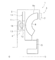
図1は、本発明の一実施形態によるトルク変動抑制装置をトルクコンバータのロックアップ装置に装着した場合の模式図である。図1において、O−Oがトルクコンバータの回転軸線である。 FIG. 1 is a schematic diagram when a torque fluctuation suppressing device according to an embodiment of the present invention is mounted on a lock-up device of a torque converter. In FIG. 1, OO is the rotational axis of the torque converter.
[全体構成]
トルクコンバータ1は、フロントカバー2と、トルクコンバータ本体3と、ロックアップ装置4と、出力ハブ5と、を有している。フロントカバー2にはエンジンからトルクが入力される。トルクコンバータ本体3は、フロントカバー2に連結されたインペラ7と、タービン8と、ステータ(図示せず)と、を有している。タービン8は出力ハブ5に連結されており、出力ハブ5の内周部には、トランスミッションの入力軸(図示せず)がスプラインによって係合可能である。
[overall structure]
The
[ロックアップ装置4]
ロックアップ装置4は、クラッチ部や、油圧によって作動するピストン等を有し、ロックアップオン状態と、ロックアップオフ状態と、を取り得る。ロックアップオン状態では、フロントカバー2に入力されたトルクは、トルクコンバータ本体3を介さずに、ロックアップ装置4を介して出力ハブ5に伝達される。一方、ロックアップオフ状態では、フロントカバー2に入力されたトルクは、トルクコンバータ本体3を介して出力ハブ5に伝達される。
[Lock-up device 4]
The lock-up
ロックアップ装置4は、入力側回転体11と、出力側回転体12と、ダンパ13と、トルク変動抑制装置14と、を有している。
The
入力側回転体11は、軸方向に移動自在なピストンを含み、フロントカバー2側の側面に摩擦部材16を有している。この摩擦部材16がフロントカバー2に押し付けられることによって、フロントカバー2から入力側回転体11にトルクが伝達される。
The input-
出力側回転体12は、入力側回転体11と軸方向に対向して配置され、入力側回転体11と相対回転自在である。出力側回転体12は出力ハブ5に連結されている。
The output-
ダンパ13は、入力側回転体11と出力側回転体12との間に配置されている。ダンパ13は、複数のトーションスプリングを有しており、入力側回転体11と出力側回転体12とを回転方向に弾性的に連結している。このダンパ13によって、入力側回転体11から出力側回転体12にトルクが伝達されるとともに、トルク変動が吸収、減衰される。
The
[トルク変動抑制装置14]
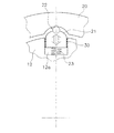
図2Aは、出力側回転体12及びトルク変動抑制装置14の正面図である。図2Aに示すように、トルク変動抑制装置14は、イナーシャリング20と、4個の遠心子21と、4個のカム機構22と、4個のコイルスプリング23と、を有している。それぞれ4個の遠心子21、カム機構22、及びコイルスプリング23は、円周方向に90°の等間隔で配置されている。なお、後述するように、カム機構22はカムフォロア25とカム26とによって構成されているが、4個のカムフォロア25に対して、カム26は合計8ヶ所に等角度間隔で形成されている。
[Torque fluctuation suppressing device 14]
FIG. 2A is a front view of the output
なお、図2Bに示すように、遠心子21の内周側に配置されたコイルスプリング23を省略することも可能である。また、以降で説明する各例においても、同様に、コイルスプリング23を設けてもよく、省略してもよい。
In addition, as shown to FIG. 2B, it is also possible to abbreviate | omit the
イナーシャリング20は、連続した円環状に形成された所定の厚みを有するプレートであり、出力側回転体12の外周側に、径方向に所定の隙間をあけて配置されている。すなわち、イナーシャリング20は、出力側回転体12と軸方向において同じ位置に配置されている。また、イナーシャリング20は、出力側回転体12の回転軸と同じ回転軸を有し、出力側回転体12とともに回転可能で、かつ出力側回転体12に対して相対回転自在である。
The
遠心子21は、出力側回転体12に配置されており、出力側回転体12の回転による遠心力によって径方向外方に移動可能である。より詳細には、図3に拡大して示すように、出力側回転体12には、外周面に凹部12aが設けられている。凹部12aは、出力側回転体12の外周面に、内周側の回転中心に向かって窪むように矩形状に形成されている。そして、この凹部12aに遠心子21が径方向に移動可能に挿入されている。遠心子21及び凹部12aは、遠心子21の側面と凹部12aとの間の摩擦係数が0.1以下になるように設定されている。また、遠心子21は、出力側回転体12とほぼ同じ厚みを有するプレートで、かつ外周面21aが円弧状に形成されている。また、遠心子21の外周面21aには、内側に窪むコロ収容部21bが形成されている。
The
カム機構22は、図3に示すように、カムフォロアとしてのコロ25と、イナーシャリング20の内周面に形成されたカム26と、から構成されている。コロ25は遠心子21のコロ収容部21bに装着されており、遠心子21とともに径方向に移動自在である。なお、コロ25は、コロ収容部21bにおいて、回転自在であっても、固定されていてもよい。カム26は、コロ25が当接する円弧状の面であり。出力側回転体12とイナーシャリング20とが所定の角度範囲で相対回転した際には、コロ25はこのカム26に沿って移動する。
As shown in FIG. 3, the
詳細は後述するが、トルク変動によって出力側回転体12とイナーシャリング20との間に回転位相差が生じたときには、コロ25とカム26との接触によって、遠心子21及びコロ25に生じた遠心力は、回転位相差が小さくなるような円周方向の力に変換される。また、トルク変動が所定値を超えるような変動値の場合は、イナーシャリング20は出力側回転体12に対して、回転位相差が生じた方向に自由に回転する。
Although details will be described later, when a rotational phase difference is generated between the output-side
コイルスプリング23は、凹部12aの底面と遠心子21の内周側の面との間に配置され、遠心子21を外周側に付勢している。このコイルスプリング23の付勢力によって、遠心子21及びコロ25はイナーシャリング20のカム26に押し付けられている。したがって、出力側回転体12が回転していない状態で、遠心子21に遠心力が作用していない場合でも、コロ25はカム26に当接する。
The
[カム機構22の作動]
図3及び図4を用いて、カム機構22の作動(トルク変動の抑制)について説明する。ロックアップオン時には、フロントカバー2に伝達されたトルクは、入力側回転体11及びダンパ13を介して出力側回転体12に伝達される。
[Operation of cam mechanism 22]
Operation of the cam mechanism 22 (torque fluctuation suppression) will be described with reference to FIGS. 3 and 4. When the lockup is on, the torque transmitted to the
トルク伝達時にトルク変動がない場合は、図3に示すような状態で、出力側回転体12及びイナーシャリング20は回転する。すなわち、カム機構22のコロ25はカム26のもっとも深い位置(円周方向の中央位置)に当接し、出力側回転体12とイナーシャリング20との回転位相差は「0」である。
When there is no torque fluctuation during torque transmission, the output
前述のように、出力側回転体12とイナーシャリング20との間の回転方向の相対変位を、「回転位相差」と称しているが、これらは、図3及び図4では、遠心子21及びコロ25の円周方向の中央位置と、カム26の円周方向の中央位置と、のずれを示すものである。
As described above, the relative displacement in the rotation direction between the output-
一方、トルクの伝達時にトルク変動が生じた場合は、図4(a)(b)に示すように、出力側回転体12とイナーシャリング20との間には、回転位相差±θが生じる。図4(a)は+R側に回転位相差+θが生じた場合を示し、図4(b)は−R側に回転位相差−θが生じた場合を示している。
On the other hand, when torque fluctuation occurs during torque transmission, a rotational phase difference ± θ is generated between the output-
図4(a)に示すように、出力側回転体12とイナーシャリング20との間に回転位相差+θが生じた場合は、カム機構22のコロ25は、カム26に沿って相対的に図4の左側に移動する。このとき、遠心子21及びコロ25には遠心力が作用しているので、カム26からコロ25が受ける反力は、図4(a)のP0の方向及び大きさとなる。この反力P0によって、円周方向の第1分力P1と、遠心子21及びコロ25を回転中心に向かって移動させる方向の第2分力P2と、が発生する。
As shown in FIG. 4A, when a rotational phase difference + θ occurs between the output-
そして、第1分力P1は、カム機構22を介して出力側回転体12を図4(a)の右方向に移動させる力となる。すなわち、出力側回転体12とイナーシャリング20との回転位相差を小さくする方向の力が、出力側回転体12に作用することになる。また、第2分力P2によって、遠心子21及びコロ25は、コイルスプリング23の付勢力に抗して、径方向内周側に移動させられる。
The first component force P1 is a force that moves the output-side
図4(b)は、出力側回転体12とイナーシャリング20との間に回転位相差−θが生じた場合を示しており、カム機構22のコロ25の移動方向、反力P0、第1分力P1、及び第2分力P2の方向が図4(a)と異なるだけで、作動は同様である。
FIG. 4B shows a case where a rotational phase difference −θ is generated between the
以上のように、トルク変動によって出力側回転体12とイナーシャリング20との間に回転位相差が生じると、遠心子21に作用する遠心力及びカム機構22の作用によって、出力側回転体12は、両者の回転位相差を小さくする方向の力(第1分力P1)を受ける。この力によって、トルク変動が抑制される。
As described above, when a rotational phase difference is generated between the output-side
以上のトルク変動を抑制する力は、遠心力、すなわち出力側回転体12の回転数によって変化するし、回転位相差及びカム26の形状によっても変化する。したがって、カム26の形状を適宜設定することによって、トルク変動抑制装置14の特性を、エンジン仕様等に応じた最適な特性にすることができる。
The force that suppresses the torque fluctuation described above varies depending on the centrifugal force, that is, the rotational speed of the output-
例えば、カム26の形状は、同じ遠心力が作用している状態で、回転位相差に応じて第1分力P1が線形に変化するような形状にすることができる。また、カム26の形状は、回転位相差に応じて第1分力P1が非線形に変化する形状にすることができる。
For example, the shape of the
トルク変動がさらに大きくなり、所定の変動値を超えるような場合は、図5に示すように、イナーシャリング20のカム26は、コロ25を通過する。すなわち、出力側回転体12に所定の変動値を超えるような過大なトルク変動が入力されたときには、カム機構22は、イナーシャリング20を、出力側回転体12に対して相対変位が生じた方向に自由に回転させる。図5では、イナーシャリング20が−R方向に回転し、カム機構として作動していたカム26が、コロ25から遠ざかっている様子を示している。
When the torque fluctuation further increases and exceeds a predetermined fluctuation value, the
なお、この後、コロ25は次のカム26(図5では時計回りの方向に形成されたカム26)に嵌り込む。そして、その際のトルク変動が所定の変動値以下であれば、図4で説明したようにカム機構22は正常に作動し、トルク変動が抑制される。また、トルク変動が所定の変動値を超えていれば、前記同様に、さらにイナーシャリング20が−R方向に回転することになる。
Thereafter, the
以上のように、過大なトルク変動が入力された場合、イナーシャリング20のカム26はコロ25を超え、イナーシャリング20は出力側回転体12に対して相対変位が生じた方向に、自由に回転する。このため、過大な力がカム機構22に作用することがなく、カム機構22の損傷を避けることができる。また、過大なトルク変動に耐え得るようにカム機構22を設計する必要がなく、カム機構22の製造コストを抑えることができる。
As described above, when an excessive torque fluctuation is input, the
[特性の例]
図6は、トルク変動抑制特性の一例を示す図である。横軸は回転数、縦軸はトルク変動(回転速度変動)である。特性Q1はトルク変動を抑制するための装置が設けられていない場合、特性Q2は従来のダイナミックダンパ装置が設けられた場合、特性Q3は本実施形態のトルク変動抑制装置14が設けられた場合を示している。
[Example of characteristics]
FIG. 6 is a diagram illustrating an example of torque fluctuation suppression characteristics. The horizontal axis represents the rotational speed, and the vertical axis represents the torque fluctuation (rotational speed fluctuation). The characteristic Q1 is a case where a device for suppressing torque fluctuation is not provided, the characteristic Q2 is a case where a conventional dynamic damper device is provided, and the characteristic Q3 is a case where the torque
この図6から明らかなように、従来のダイナミックダンパ装置が設けられた装置(特性Q2)では、特定の回転数域のみについてトルク変動を抑制することができる。一方、本実施形態(特性Q3)では、すべての回転数域においてトルク変動を抑制することができる。 As is apparent from FIG. 6, in the device (characteristic Q2) provided with the conventional dynamic damper device, it is possible to suppress the torque fluctuation only in a specific rotational speed range. On the other hand, in the present embodiment (characteristic Q3), torque fluctuation can be suppressed in all the rotational speed ranges.
[カム機構22の変形例]
(変形例1)
図7に示す実施形態では、遠心子21と凹部12aの側面(円周方向の端面)との間に、ベアリングや、ローラ、樹脂レース、シート等の摩擦低減部材30が配置されている。このような摩擦低減部材30を配置することによって、遠心子21が移動する際に、よりスムーズに移動することができる。
[Modification of Cam Mechanism 22]
(Modification 1)
In the embodiment shown in FIG. 7, a
(変形例2)
図8に示す実施形態では、遠心子及びイナーシャリングの形状が前記実施形態と異なっている。すなわち、遠心子31の外周面31aは、内周側に凹む円弧状に形成されている。この外周面31aがカムとして機能している。一方、イナーシャリング40の内周面には、カムフォロアとしてのコロ25を収容するコロ収容部40aが形成されている。そして、コロ25がカムとしての外周面31aに当接している。
(Modification 2)
In the embodiment shown in FIG. 8, the shape of the centrifuge and the inertia ring is different from that of the above embodiment. That is, the outer
この実施形態では、カム機構32のカムフォロアとしてのコロ25がイナーシャリング40に配置され、カム31aが遠心子31に設けられていることを除いて、他の構成や作動は前記実施形態と同様である。
In this embodiment, the
(変形例3)
図9は、カム機構のカムフォロアを遠心子と一体で形成した例を示している。すなわち、遠心子41の外周面には、外周側に突出する半円形状の突起41aが形成されている。この突起41aがカムフォロアとして機能し、イナーシャリング20に形成されたカム26に接触して、前記実施形態と同様の作動をする。
(Modification 3)
FIG. 9 shows an example in which the cam follower of the cam mechanism is formed integrally with the centrifuge. That is, a
(変形例4)
図10は、イナーシャリング側に遠心子が配置され、出力側回転体の内周面にカム機構が配置された例である。イナーシャリング50の内周面には、矩形の凹部50aが形成されており、この凹部50aに遠心子51が径方向に移動自在に配置されている。また、遠心子51と凹部50aの底面との間には、遠心子51を外周側に引き込む引張バネ53が設けられている。
(Modification 4)
FIG. 10 shows an example in which a centrifuge is arranged on the inertia ring side and a cam mechanism is arranged on the inner peripheral surface of the output side rotating body. A rectangular recess 50a is formed on the inner peripheral surface of the
一方、カム機構52は、遠心子51の先端(内周端)に設けられたカムフォロアとしてのコロ55と、出力側回転体57の内周面に形成されたカム56と、から構成されている。カム56の形状は、前記実施形態と同様である。コロ55は、引張バネ53の付勢力によって、常にカム56に当接している。
On the other hand, the
この実施形態では、イナーシャリング50が出力側回転体57とともに回転すると、遠心子51には外周側に向かう遠心力が発生する。この遠心力によって、コロ55がカム56に押し付けられる。そして、トルク変動が生じた場合の動作は、前記実施形態と同様である。
In this embodiment, when the
[他の実施形態]
本発明は以上のような実施形態に限定されるものではなく、本発明の範囲を逸脱することなく種々の変形又は修正が可能である。
[Other Embodiments]
The present invention is not limited to the above-described embodiments, and various changes or modifications can be made without departing from the scope of the present invention.
(a)出力側回転体とイナーシャリングとの位置関係は前記実施形態に限定されない。例えば、図11に示すように、前記実施形態とは逆に、出力側回転体60を外周側に配置し、イナーシャリング61を内周側に配置してもよい。カム機構22等の他の構成については、前記実施形態と同様である。
(A) The positional relationship between the output side rotator and the inertia ring is not limited to the above embodiment. For example, as shown in FIG. 11, the output
(b)図12に示すように、トルク変動抑制装置14を構成するイナーシャリングをタービン8に連結するようにしてもよい。この場合は、タービン8は出力ハブ5には連結されていない。この場合は、イナーシャリングがタービン8(正確には、タービンシェル8a)に連結されているので、タービンシェル8aも、イナーシャリングとともに、イナーシャ(慣性体)として機能する。
(B) As shown in FIG. 12, the inertia ring constituting the torque
なお、図12に示す実施形態では、ロックアップオフの状態では、トルクコンバータ本体3からのトルクは、タービン8を介してトルク変動抑制装置14から出力側回転体12に伝達され、出力ハブ5に出力される。このとき、イナーシャリングからカム機構を介して出力側回転体12にトルク(変動トルクではなく、定常的な平均トルク)を伝達するのは困難である。このため、カム機構の作動角度を確保した上で、バネあるいは機械的なストッパー等を用いてトルクが伝達されるように構成する必要がある。
In the embodiment shown in FIG. 12, in the lockup-off state, torque from the torque converter
(c)前記実施形態では、トルク変動が所定の変動値以下の場合にカム機構を作動させるようにしたが、トルク変動の変動値が非常に小さい場合は、トルク変動がない場合と同様に、カム機構を作動させないような仕様にすることも可能である。 (C) In the above embodiment, the cam mechanism is operated when the torque fluctuation is equal to or smaller than the predetermined fluctuation value. However, when the fluctuation value of the torque fluctuation is very small, as in the case where there is no torque fluctuation, It is also possible to make specifications so that the cam mechanism is not operated.
[適用例]
以上のようなトルク変動抑制装置を、トルクコンバータや他の動力伝達装置に適用する場合、種々の配置が可能である。以下に、トルクコンバータや他の動力伝達装置の模式図を利用して、具体的な適用例について説明する。
[Application example]
When the torque fluctuation suppressing device as described above is applied to a torque converter or another power transmission device, various arrangements are possible. Below, a specific application example is demonstrated using the schematic diagram of a torque converter or another power transmission device.
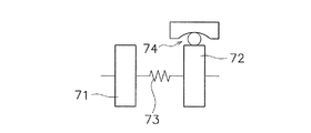
(1)図13は、トルクコンバータを模式的に示した図であり、トルクコンバータは、入力側回転体71と、出力側回転体72と、両回転体71,72の間に設けられたダンパ73と、を有している。入力側回転体71は、フロントカバー、ドライブプレート、ピストン等の部材を含む。出力側回転体72は、ドリブンプレート、タービンハブを含む。ダンパ73は複数のトーションスプリングを含む。
(1) FIG. 13 is a diagram schematically showing a torque converter. The torque converter includes an input-
この図13に示した例では、入力側回転体71のいずれかに遠心子が設けられており、この遠心子に作用する遠心力を利用して作動するカム機構74が設けられている。カム機構74については、前記各実施形態に示された構成と同様の構成を適用できる。
In the example shown in FIG. 13, a centrifuge is provided in one of the
(2)図14に示したトルクコンバータは、出力側回転体72のいずれかに遠心子が設けられており、この遠心子に作用する遠心力を利用して作動するカム機構74が設けられている。カム機構74については、前記各実施形態に示された構成と同様の構成を適用できる。
(2) The torque converter shown in FIG. 14 is provided with a centrifuge in one of the
(3)図15に示したトルクコンバータは、図13及び図14に示した構成に加えて、別のダンパ75と、2つのダンパ73,75の間に設けられた中間部材76と、を有している。中間部材76は、入力側回転体71及び出力側回転体72と相対回転自在であり、2つのダンパ73,75を直列的に作用させる。
(3) The torque converter shown in FIG. 15 has another
図15に示した例では、中間部材76に遠心子が設けられており、この遠心子に作用する遠心力を利用して作動するカム機構74が設けられている。カム機構74については、前記各実施形態に示された構成と同様の構成を適用できる。
In the example shown in FIG. 15, the
(4)図16に示したトルクコンバータは、フロート部材77を有している。フロート部材77は、ダンパ73を構成するトーションスプリングを支持するために部材であり、例えば、環状に形成されて、トーションスプリングの外周及び少なくとも一方の側面を覆うように配置されている。また、フロート部材77は、入力側回転体71及び出力側回転体72と相対回転自在であり、かつダンパ73のトーションスプリングとの摩擦によってダンパ73に連れ回る。すなわち、フロート部材77も回転する。
(4) The torque converter shown in FIG. 16 has a
この図16に示した例では、フロート部材77に遠心子78が設けられており、この遠心子78に作用する遠心力を利用して作動するカム機構74が設けられている。カム機構74については、前記各実施形態に示された構成と同様の構成を適用できる。
In the example shown in FIG. 16, the
(5)図17は、2つの慣性体81,82を有するフライホイール80と、クラッチ装置84と、を有する動力伝達装置の模式図である。すなわち、エンジンとクラッチ装置84との間に配置されたフライホイール80は、第1慣性体81と、第1慣性体81と相対回転自在に配置された第2慣性体82と、2つの慣性体81,82の間に配置されたダンパ83と、を有している。なお、第2慣性体82は、クラッチ装置84を構成するクラッチカバーも含む。
(5) FIG. 17 is a schematic diagram of a power transmission device having a
図17に示した例では、第2慣性体82を構成する回転部材のいずれかに遠心子が設けられており、この遠心子に作用する遠心力を利用して作動するカム機構85が設けられている。カム機構85については、前記各実施形態に示された構成と同様の構成を適用できる。
In the example shown in FIG. 17, a centrifuge is provided in any of the rotating members that constitute the second
(6)図18は、図17と同様の動力伝達装置において、第1慣性体81に遠心子が設けられた例である。そして、この遠心子に作用する遠心力を利用して作動するカム機構85が設けられている。カム機構85については、前記各実施形態に示された構成と同様の構成を適用できる。
(6) FIG. 18 is an example in which a centrifuge is provided on the first
(7)図19に示した動力伝達装置は、図17及び図18に示した構成に加えて、別のダンパ86と、2つのダンパ83,86の間に設けられた中間部材87と、を有している。中間部材87は、第1慣性体81及び第2慣性体82と相対回転自在である。
(7) In addition to the configuration shown in FIGS. 17 and 18, the power transmission device shown in FIG. 19 includes another
図19に示した例では、中間部材87に遠心子88が設けられており、この遠心子88に作用する遠心力を利用して作動するカム機構85が設けられている。カム機構85については、前記各実施形態に示された構成と同様の構成を適用できる。
In the example shown in FIG. 19, the
(8)図20は、1つのフライホイールにクラッチ装置が設けられた動力伝達装置の模式図である。図20の第1慣性体91は、1つのフライホイールと、クラッチ装置92のクラッチカバーと、を含む。この例では、第1慣性体91を構成する回転部材のいずれかに遠心子が設けられており、この遠心子に作用する遠心力を利用して作動するカム機構94が設けられている。カム機構94については、前記各実施形態に示された構成と同様の構成を適用できる。
(8) FIG. 20 is a schematic diagram of a power transmission device in which a clutch device is provided on one flywheel. The
(9)図21は、図20と同様の動力伝達装置において、クラッチ装置92の出力側に遠心子95が設けられた例である。そして、この遠心子95に作用する遠心力を利用して作動するカム機構94が設けられている。カム機構94については、前記各実施形態に示された構成と同様の構成を適用できる。
(9) FIG. 21 is an example in which a
(10)図面には示していないが、本発明のトルク変動抑制装置を、トランスミッションを構成する回転部材のいずれかに配置してもよいし、さらにはトランスミッションの出力側のシャフト(プロペラシャフト又はドライブシャフト)に配置してもよい。 (10) Although not shown in the drawings, the torque fluctuation suppressing device of the present invention may be disposed on any of the rotating members constituting the transmission, and further, the shaft (propeller shaft or drive) on the output side of the transmission (Shaft).
(11)他の適用例として、従来から周知のダイナミックダンパ装置や、振り子式ダンパ装置が設けられた動力伝達装置に、本発明のトルク変動抑制装置をさらに適用してもよい。 (11) As another application example, the torque fluctuation suppressing device of the present invention may be further applied to a conventionally known dynamic damper device or a power transmission device provided with a pendulum type damper device.
1 トルクコンバータ
12,57,60 出力側回転体
14 トルク変動抑制装置
20,40,50,61 イナーシャリング(質量体)
21,31,41,51,78,88,95 遠心子
22,32,74,85,94 カム機構
23 コイルスプリング(付勢部材)
25 コロ
26,31a カム
30 スラスト部材
65 イナーシャ体
66 保持リング
71 入力側回転体
72 出力側回転体
73,75,83,86 ダンパ
76,87 中間部材
77 フロート部材
80 フライホイール
81,91 第1慣性体
82 第2慣性体
84,92 クラッチ装置
DESCRIPTION OF
21, 31, 41, 51, 78, 88, 95
25
Claims (23)
前記回転体とともに回転可能であり、かつ前記回転体に対して相対回転自在に配置された質量体と、
前記回転体及び前記質量体の回転による遠心力を受けるように配置された遠心子と、
前記遠心子に作用する遠心力を受けて、前記回転体と前記質量体との間に回転方向における相対変位が生じたときには、前記遠心力を、前記相対変位が小さくなる方向の円周方向力に変換するとともに、前記回転体に所定の大きさ以上のトルク変動が入力されたときには、前記回転体に対して前記質量体を自由に回転させる、カム機構と、
を備えたトルク変動抑制装置。 A torque fluctuation suppressing device for suppressing torque fluctuation of a rotating body to which torque is input,
A mass body that is rotatable together with the rotating body and is arranged to be rotatable relative to the rotating body;
A centrifuge arranged to receive a centrifugal force due to rotation of the rotating body and the mass body;
When a relative displacement in the rotational direction occurs between the rotating body and the mass body due to the centrifugal force acting on the centrifuge, the centrifugal force is converted into a circumferential force in a direction in which the relative displacement is reduced. And a cam mechanism that freely rotates the mass body relative to the rotating body when a torque fluctuation of a predetermined magnitude or more is input to the rotating body.
Torque fluctuation suppressing device comprising:
前記トルク変動が所定の変動値以下の場合は、前記遠心力を、前記相対変位が小さくなる方向の円周方向力に変換し、
前記トルク変動が前記所定の変動値を超える場合は、前記質量体を前記回転体に対して自由に回転させる、
請求項1に記載のトルク変動抑制装置。 The cam mechanism is
When the torque fluctuation is equal to or less than a predetermined fluctuation value, the centrifugal force is converted into a circumferential force in a direction in which the relative displacement is reduced,
When the torque fluctuation exceeds the predetermined fluctuation value, the mass body is freely rotated with respect to the rotating body,
The torque fluctuation suppressing device according to claim 1.
前記遠心子は前記凹部に径方向移動自在に収容されている、
請求項4に記載のトルク変動抑制装置。 The rotating body or mass body arranged on the inner peripheral side has a recess on the outer peripheral surface,
The centrifuge is accommodated in the recess so as to be movable in the radial direction.
The torque fluctuation suppressing device according to claim 4.
前記遠心子に設けられたカムフォロアと、
外周側に配置された前記回転体又は前記質量体の内周面に形成され、前記カムフォロアが当接し前記回転体と前記質量体との間の回転方向における相対変位量に応じて前記円周方向力が変化するような形状を有するカムと、
を有する、
請求項5から7のいずれかに記載のトルク変動抑制装置。 The cam mechanism is
A cam follower provided in the centrifuge;
Formed on the inner peripheral surface of the rotating body or the mass body arranged on the outer peripheral side, the cam follower comes into contact with the circumferential direction according to the relative displacement amount in the rotational direction between the rotating body and the mass body A cam having a shape in which the force changes;
Having
The torque fluctuation suppressing device according to any one of claims 5 to 7.
外周側に配置された前記回転体又は前記質量体の内周面に形成されたカムフォロアと、
外周面が前記カムフォロアに当接し、前記遠心子に設けられ、前記回転体と前記質量体との間の回転方向の相対変位量に応じて前記円周方向力が変化するような形状を有するカムと、
を有する、
請求項5から7のいずれかに記載のトルク変動抑制装置。 The cam mechanism is
A cam follower formed on an inner peripheral surface of the rotating body or the mass body arranged on the outer peripheral side;
An outer peripheral surface abuts on the cam follower, is provided on the centrifuge, and has a shape such that the circumferential force changes according to the amount of relative displacement in the rotational direction between the rotating body and the mass body. When,
Having
The torque fluctuation suppressing device according to any one of claims 5 to 7.
前記遠心子は前記凹部に径方向移動自在に収容されており、
前記カム機構は、
前記遠心子に設けられたカムフォロアと、
内周側に配置された前記回転体又は前記質量体の内周面に形成され、前記カムフォロアが当接し前記回転体と前記質量体との間の回転方向の相対変位量に応じて前記円周方向力が変化するような形状を有するカムと、
を有する、
請求項4に記載のトルク変動抑制装置。 The rotating body or mass body arranged on the outer peripheral side has a recess on the inner peripheral surface,
The centrifuge is accommodated in the recess so as to be movable in the radial direction,
The cam mechanism is
A cam follower provided in the centrifuge;
It is formed on the inner peripheral surface of the rotating body or the mass body arranged on the inner peripheral side, and the cam follower comes into contact with the circumference according to the amount of relative displacement in the rotational direction between the rotating body and the mass body. A cam having a shape in which the directional force changes,
Having
The torque fluctuation suppressing device according to claim 4.
前記質量体に対して円周方向に移動不能に保持されたコロと、 A roller held immovable in the circumferential direction with respect to the mass body;
前記遠心子の外周面において内周側に凹む円弧状に形成され、前記コロに当接し、前記回転体と前記質量体との間の回転方向の相対変位量に応じて前記円周方向力が変化するような形状を有するカムと、 The outer circumferential surface of the centrifuge is formed in a circular arc shape that is recessed toward the inner circumferential side, abuts on the roller, and the circumferential force depends on the amount of relative displacement in the rotational direction between the rotating body and the mass body. A cam having a changing shape;
を有する、Having
請求項1に記載のトルク変動抑制装置。The torque fluctuation suppressing device according to claim 1.
前記エンジンからのトルクが入力される入力側回転体と、
前記トランスミッションにトルクを出力する出力側回転体と、
前記入力側回転体と前記出力側回転体との間に配置されたダンパと、
請求項1から14のいずれかに記載のトルク変動抑制装置と、
を備えたトルクコンバータ。 A torque converter disposed between the engine and the transmission,
An input-side rotating body to which torque from the engine is input;
An output-side rotating body that outputs torque to the transmission;
A damper disposed between the input side rotating body and the output side rotating body;
The torque fluctuation suppressing device according to any one of claims 1 to 14 ,
Torque converter with
前記入力側回転体からトルクが入力される第1ダンパと、
前記出力側回転体にトルクを出力する第2ダンパと、
前記第1ダンパと前記第2ダンパとの間に設けられた中間部材と、
を有し、
前記トルク変動抑制装置は前記中間部材に配置されている、
請求項15に記載のトルクコンバータ。 The damper is
A first damper to which torque is input from the input side rotating body;
A second damper that outputs torque to the output-side rotating body;
An intermediate member provided between the first damper and the second damper;
Have
The torque fluctuation suppressing device is disposed on the intermediate member,
The torque converter according to claim 15 .
前記入力側回転体及び前記出力側回転体に対して相対回転自在であり、前記複数のコイルスプリングを支持するフロート部材をさらに備え、
前記トルク変動抑制装置は前記フロート部材に配置されている、
請求項15に記載のトルクコンバータ。 The damper has a plurality of coil springs,
A float member that is relatively rotatable with respect to the input side rotating body and the output side rotating body, and that supports the plurality of coil springs;
The torque fluctuation suppressing device is disposed on the float member;
The torque converter according to claim 15 .
前記フライホイールの前記第2慣性体に設けられたクラッチ装置と、
請求項1から14のいずれかに記載のトルク変動抑制装置と、
を備えた動力伝達装置。 A first inertial body that rotates about a rotation axis; a second inertial body that rotates about the rotation axis and is rotatable relative to the first inertial body; and the first inertial body and the second inertial body. A flywheel having a damper disposed therebetween,
A clutch device provided in the second inertial body of the flywheel;
The torque fluctuation suppressing device according to any one of claims 1 to 14 ,
Power transmission device with
前記第1慣性体からトルクが入力される第1ダンパと、
前記第2慣性体にトルクを出力する第2ダンパと、
前記第1ダンパと前記第2ダンパとの間に設けられた中間部材と、
を有し、
前記トルク変動抑制装置は前記中間部材に配置されている、
請求項20に記載の動力伝達装置。 The damper is
A first damper that receives torque from the first inertial body;
A second damper that outputs torque to the second inertial body;
An intermediate member provided between the first damper and the second damper;
Have
The torque fluctuation suppressing device is disposed on the intermediate member,
The power transmission device according to claim 20 .
Priority Applications (21)
| Application Number | Priority Date | Filing Date | Title |
|---|---|---|---|
| JP2015208759A JP6577823B2 (en) | 2015-10-23 | 2015-10-23 | Torque fluctuation suppressing device, torque converter, and power transmission device |
| US15/576,784 US10184542B2 (en) | 2015-08-20 | 2016-07-21 | Torque fluctuation inhibiting device, torque converter and power transmission device |
| CN201680047202.9A CN107923482B (en) | 2015-08-20 | 2016-07-21 | Torque fluctuation inhibits device, fluid torque-converter and power transmission |
| DE112016003113.0T DE112016003113T5 (en) | 2015-08-20 | 2016-07-21 | Torque fluctuation prevention device, torque converter and power transmission device |
| CN201680046952.4A CN107923481B (en) | 2015-08-20 | 2016-07-21 | Torque fluctuation suppression device, torque converter, and power transmission device |
| PCT/JP2016/071333 WO2017029932A1 (en) | 2015-08-20 | 2016-07-21 | Torque-fluctuation suppression device, torque converter, and power transmission device |
| KR1020177037041A KR102520861B1 (en) | 2015-08-20 | 2016-07-21 | Torque Suppressor, Torque Converter and Power Transmission |
| PCT/JP2016/071332 WO2017029931A1 (en) | 2015-08-20 | 2016-07-21 | Torque-fluctuation suppression device, torque converter, and power transmission device |
| US15/576,755 US10619702B2 (en) | 2015-08-20 | 2016-07-21 | Torque fluctuation inhibiting device, torque converter and power transmission device |
| DE112016003115.7T DE112016003115T5 (en) | 2015-08-20 | 2016-07-21 | Torque fluctuation prevention device, torque converter and power transmission device |
| KR1020177037039A KR20180042163A (en) | 2015-08-20 | 2016-07-21 | Torque fluctuation suppression device, torque converter and power transmission device |
| PCT/JP2016/071504 WO2017029940A1 (en) | 2015-08-20 | 2016-07-22 | Torque-fluctuation suppression device, torque converter, and power transmission device |
| CN201680047359.1A CN107923483B (en) | 2015-08-20 | 2016-07-22 | Torque fluctuation inhibits device, torque converter and power transmission |
| US15/576,776 US10626949B2 (en) | 2015-08-20 | 2016-07-22 | Torque fluctuation inhibiting device, torque converter and power transmission device |
| US15/576,788 US10626950B2 (en) | 2015-08-20 | 2016-07-22 | Torque fluctuation inhibiting device, torque converter and power transmission device |
| DE112016003043.6T DE112016003043T5 (en) | 2015-08-20 | 2016-07-22 | Torque fluctuation prevention device, torque converter and power transmission device |
| KR1020177037040A KR20180044234A (en) | 2015-08-20 | 2016-07-22 | Torque fluctuation suppression device, torque converter and power transmission device |
| DE112016002922.5T DE112016002922T5 (en) | 2015-08-20 | 2016-07-22 | Torque fluctuation prevention device, torque converter and power transmission device |
| KR1020177037042A KR20180042165A (en) | 2015-08-20 | 2016-07-22 | Torque fluctuation suppression device, torque converter and power transmission device |
| CN201680047456.0A CN107923484B (en) | 2015-08-20 | 2016-07-22 | Torque fluctuation inhibits device, torque converter and power transmission |
| PCT/JP2016/071503 WO2017029939A1 (en) | 2015-08-20 | 2016-07-22 | Torque-fluctuation suppression device, torque converter, and power transmission device |
Applications Claiming Priority (1)
| Application Number | Priority Date | Filing Date | Title |
|---|---|---|---|
| JP2015208759A JP6577823B2 (en) | 2015-10-23 | 2015-10-23 | Torque fluctuation suppressing device, torque converter, and power transmission device |
Publications (3)
| Publication Number | Publication Date |
|---|---|
| JP2017082819A JP2017082819A (en) | 2017-05-18 |
| JP2017082819A5 JP2017082819A5 (en) | 2018-10-25 |
| JP6577823B2 true JP6577823B2 (en) | 2019-09-18 |
Family
ID=58710522
Family Applications (1)
| Application Number | Title | Priority Date | Filing Date |
|---|---|---|---|
| JP2015208759A Active JP6577823B2 (en) | 2015-08-20 | 2015-10-23 | Torque fluctuation suppressing device, torque converter, and power transmission device |
Country Status (1)
| Country | Link |
|---|---|
| JP (1) | JP6577823B2 (en) |
Families Citing this family (5)
| Publication number | Priority date | Publication date | Assignee | Title |
|---|---|---|---|---|
| JP2018013144A (en) * | 2016-07-19 | 2018-01-25 | 株式会社エクセディ | Dynamic vibration absorber |
| JP6733506B2 (en) * | 2016-11-07 | 2020-08-05 | トヨタ自動車株式会社 | Torsional vibration reduction device |
| JP2018132159A (en) | 2017-02-17 | 2018-08-23 | 株式会社エクセディ | Torque fluctuation suppressing device, torque converter, and power transmission device |
| JP7047683B2 (en) * | 2018-09-14 | 2022-04-05 | トヨタ自動車株式会社 | Torsion vibration reduction device |
| JP7056539B2 (en) * | 2018-12-17 | 2022-04-19 | トヨタ自動車株式会社 | Pendulum type torsional vibration reduction device |
Family Cites Families (12)
| Publication number | Priority date | Publication date | Assignee | Title |
|---|---|---|---|---|
| US2079226A (en) * | 1930-12-19 | 1937-05-04 | Sarazin Kaoul Reland Raymond | Means adapted to reduce the torsional oscillations of crankshafts |
| JP3657403B2 (en) * | 1997-09-12 | 2005-06-08 | 株式会社エクセディ | Dynamic damper and flywheel assembly |
| DE19954273A1 (en) * | 1999-11-11 | 2001-05-17 | Mannesmann Sachs Ag | Vibration damping system esp. for vehicle drive system including basic body rotatable about axis of rotation and at least one deflection mass and deflection track assigned to this |
| JP2003065392A (en) * | 2001-08-23 | 2003-03-05 | Toyota Industries Corp | Rotor and rotary machine |
| WO2014033043A1 (en) * | 2012-08-27 | 2014-03-06 | Bayerische Motoren Werke Aktiengesellschaft | Centrifugal pendulum |
| JP5991085B2 (en) * | 2012-08-29 | 2016-09-14 | アイシン精機株式会社 | Torque fluctuation absorber |
| JP5924279B2 (en) * | 2013-01-29 | 2016-05-25 | トヨタ自動車株式会社 | Torsional vibration damping device |
| JP2014152835A (en) * | 2013-02-06 | 2014-08-25 | Aisin Seiki Co Ltd | Power transmission |
| JP6149415B2 (en) * | 2013-02-06 | 2017-06-21 | アイシン精機株式会社 | Power transmission device |
| JP6245871B2 (en) * | 2013-06-04 | 2017-12-13 | 株式会社エクセディ | Torque converter lockup device |
| EP2899426A1 (en) * | 2014-01-22 | 2015-07-29 | Schaeffler Technologies AG & Co. KG | Torsional vibration damper |
| JP6142812B2 (en) * | 2014-01-31 | 2017-06-07 | アイシン・エィ・ダブリュ株式会社 | Starting device |
-
2015
- 2015-10-23 JP JP2015208759A patent/JP6577823B2/en active Active
Also Published As
| Publication number | Publication date |
|---|---|
| JP2017082819A (en) | 2017-05-18 |
Similar Documents
| Publication | Publication Date | Title |
|---|---|---|
| WO2017029940A1 (en) | Torque-fluctuation suppression device, torque converter, and power transmission device | |
| JP6653538B2 (en) | Torque fluctuation suppressing device, torque converter, and power transmission device | |
| WO2017043316A1 (en) | Torque-fluctuation-minimizing device, torque converter, and motive power transmission device | |
| JP6577823B2 (en) | Torque fluctuation suppressing device, torque converter, and power transmission device | |
| WO2018150660A1 (en) | Torque fluctuation suppressing device, torque converter, and power transmission device | |
| JP6657041B2 (en) | Torque fluctuation suppressing device, torque converter, and power transmission device | |
| JP6757680B2 (en) | Torque fluctuation suppression device, torque converter, and power transmission device | |
| WO2018150777A1 (en) | Torque fluctuation suppression device, torque converter, and power transmission device | |
| JP2019039456A (en) | Torque fluctuation suppression device, torque converter, and power transmission device | |
| JP7300284B2 (en) | Torque fluctuation suppressor and torque converter | |
| JP6539180B2 (en) | Torque fluctuation suppressing device, torque converter, and power transmission device | |
| JP6656868B2 (en) | Torque fluctuation suppressing device, torque converter, and power transmission device | |
| JP7263066B2 (en) | Torque fluctuation suppressor and torque converter | |
| JP7218221B2 (en) | Torque fluctuation suppressor and torque converter | |
| JP6682572B2 (en) | Torque fluctuation suppression device | |
| JP2019052714A (en) | Torque fluctuation control device, torque converter and power transmission device | |
| JP2020076505A (en) | Torque fluctuation suppression device, torque converter, and power transmission device | |
| JP2019138421A (en) | Torque fluctuation suppression device, torque converter, and power transmission device |
Legal Events
| Date | Code | Title | Description |
|---|---|---|---|
| A521 | Request for written amendment filed |
Free format text: JAPANESE INTERMEDIATE CODE: A523 Effective date: 20180911 |
|
| A621 | Written request for application examination |
Free format text: JAPANESE INTERMEDIATE CODE: A621 Effective date: 20180911 |
|
| A131 | Notification of reasons for refusal |
Free format text: JAPANESE INTERMEDIATE CODE: A131 Effective date: 20190416 |
|
| A521 | Request for written amendment filed |
Free format text: JAPANESE INTERMEDIATE CODE: A523 Effective date: 20190527 |
|
| TRDD | Decision of grant or rejection written | ||
| A01 | Written decision to grant a patent or to grant a registration (utility model) |
Free format text: JAPANESE INTERMEDIATE CODE: A01 Effective date: 20190806 |
|
| A61 | First payment of annual fees (during grant procedure) |
Free format text: JAPANESE INTERMEDIATE CODE: A61 Effective date: 20190823 |
|
| R150 | Certificate of patent or registration of utility model |
Ref document number: 6577823 Country of ref document: JP Free format text: JAPANESE INTERMEDIATE CODE: R150 |
|
| R250 | Receipt of annual fees |
Free format text: JAPANESE INTERMEDIATE CODE: R250 |