JP6577663B2 - コンバータおよびそれを用いた電力変換装置 - Google Patents
コンバータおよびそれを用いた電力変換装置 Download PDFInfo
- Publication number
- JP6577663B2 JP6577663B2 JP2018511789A JP2018511789A JP6577663B2 JP 6577663 B2 JP6577663 B2 JP 6577663B2 JP 2018511789 A JP2018511789 A JP 2018511789A JP 2018511789 A JP2018511789 A JP 2018511789A JP 6577663 B2 JP6577663 B2 JP 6577663B2
- Authority
- JP
- Japan
- Prior art keywords
- transistor
- transistors
- voltage
- diodes
- output terminal
- Prior art date
- Legal status (The legal status is an assumption and is not a legal conclusion. Google has not performed a legal analysis and makes no representation as to the accuracy of the status listed.)
- Active
Links
Images


Classifications
-
- H—ELECTRICITY
- H02—GENERATION; CONVERSION OR DISTRIBUTION OF ELECTRIC POWER
- H02M—APPARATUS FOR CONVERSION BETWEEN AC AND AC, BETWEEN AC AND DC, OR BETWEEN DC AND DC, AND FOR USE WITH MAINS OR SIMILAR POWER SUPPLY SYSTEMS; CONVERSION OF DC OR AC INPUT POWER INTO SURGE OUTPUT POWER; CONTROL OR REGULATION THEREOF
- H02M7/00—Conversion of ac power input into dc power output; Conversion of dc power input into ac power output
- H02M7/02—Conversion of ac power input into dc power output without possibility of reversal
- H02M7/04—Conversion of ac power input into dc power output without possibility of reversal by static converters
- H02M7/12—Conversion of ac power input into dc power output without possibility of reversal by static converters using discharge tubes with control electrode or semiconductor devices with control electrode
- H02M7/21—Conversion of ac power input into dc power output without possibility of reversal by static converters using discharge tubes with control electrode or semiconductor devices with control electrode using devices of a triode or transistor type requiring continuous application of a control signal
- H02M7/217—Conversion of ac power input into dc power output without possibility of reversal by static converters using discharge tubes with control electrode or semiconductor devices with control electrode using devices of a triode or transistor type requiring continuous application of a control signal using semiconductor devices only
-
- H—ELECTRICITY
- H02—GENERATION; CONVERSION OR DISTRIBUTION OF ELECTRIC POWER
- H02M—APPARATUS FOR CONVERSION BETWEEN AC AND AC, BETWEEN AC AND DC, OR BETWEEN DC AND DC, AND FOR USE WITH MAINS OR SIMILAR POWER SUPPLY SYSTEMS; CONVERSION OF DC OR AC INPUT POWER INTO SURGE OUTPUT POWER; CONTROL OR REGULATION THEREOF
- H02M1/00—Details of apparatus for conversion
- H02M1/32—Means for protecting converters other than automatic disconnection
-
- H—ELECTRICITY
- H02—GENERATION; CONVERSION OR DISTRIBUTION OF ELECTRIC POWER
- H02M—APPARATUS FOR CONVERSION BETWEEN AC AND AC, BETWEEN AC AND DC, OR BETWEEN DC AND DC, AND FOR USE WITH MAINS OR SIMILAR POWER SUPPLY SYSTEMS; CONVERSION OF DC OR AC INPUT POWER INTO SURGE OUTPUT POWER; CONTROL OR REGULATION THEREOF
- H02M7/00—Conversion of ac power input into dc power output; Conversion of dc power input into ac power output
- H02M7/02—Conversion of ac power input into dc power output without possibility of reversal
- H02M7/04—Conversion of ac power input into dc power output without possibility of reversal by static converters
- H02M7/12—Conversion of ac power input into dc power output without possibility of reversal by static converters using discharge tubes with control electrode or semiconductor devices with control electrode
-
- H—ELECTRICITY
- H02—GENERATION; CONVERSION OR DISTRIBUTION OF ELECTRIC POWER
- H02M—APPARATUS FOR CONVERSION BETWEEN AC AND AC, BETWEEN AC AND DC, OR BETWEEN DC AND DC, AND FOR USE WITH MAINS OR SIMILAR POWER SUPPLY SYSTEMS; CONVERSION OF DC OR AC INPUT POWER INTO SURGE OUTPUT POWER; CONTROL OR REGULATION THEREOF
- H02M7/00—Conversion of ac power input into dc power output; Conversion of dc power input into ac power output
- H02M7/42—Conversion of dc power input into ac power output without possibility of reversal
- H02M7/44—Conversion of dc power input into ac power output without possibility of reversal by static converters
- H02M7/48—Conversion of dc power input into ac power output without possibility of reversal by static converters using discharge tubes with control electrode or semiconductor devices with control electrode
- H02M7/483—Converters with outputs that each can have more than two voltages levels
- H02M7/487—Neutral point clamped inverters
-
- H—ELECTRICITY
- H02—GENERATION; CONVERSION OR DISTRIBUTION OF ELECTRIC POWER
- H02M—APPARATUS FOR CONVERSION BETWEEN AC AND AC, BETWEEN AC AND DC, OR BETWEEN DC AND DC, AND FOR USE WITH MAINS OR SIMILAR POWER SUPPLY SYSTEMS; CONVERSION OF DC OR AC INPUT POWER INTO SURGE OUTPUT POWER; CONTROL OR REGULATION THEREOF
- H02M7/00—Conversion of ac power input into dc power output; Conversion of dc power input into ac power output
- H02M7/66—Conversion of ac power input into dc power output; Conversion of dc power input into ac power output with possibility of reversal
- H02M7/68—Conversion of ac power input into dc power output; Conversion of dc power input into ac power output with possibility of reversal by static converters
- H02M7/72—Conversion of ac power input into dc power output; Conversion of dc power input into ac power output with possibility of reversal by static converters using discharge tubes with control electrode or semiconductor devices with control electrode
- H02M7/79—Conversion of ac power input into dc power output; Conversion of dc power input into ac power output with possibility of reversal by static converters using discharge tubes with control electrode or semiconductor devices with control electrode using devices of a triode or transistor type requiring continuous application of a control signal
- H02M7/797—Conversion of ac power input into dc power output; Conversion of dc power input into ac power output with possibility of reversal by static converters using discharge tubes with control electrode or semiconductor devices with control electrode using devices of a triode or transistor type requiring continuous application of a control signal using semiconductor devices only
-
- H—ELECTRICITY
- H02—GENERATION; CONVERSION OR DISTRIBUTION OF ELECTRIC POWER
- H02J—CIRCUIT ARRANGEMENTS OR SYSTEMS FOR SUPPLYING OR DISTRIBUTING ELECTRIC POWER; SYSTEMS FOR STORING ELECTRIC ENERGY
- H02J9/00—Circuit arrangements for emergency or stand-by power supply, e.g. for emergency lighting
- H02J9/04—Circuit arrangements for emergency or stand-by power supply, e.g. for emergency lighting in which the distribution system is disconnected from the normal source and connected to a standby source
- H02J9/06—Circuit arrangements for emergency or stand-by power supply, e.g. for emergency lighting in which the distribution system is disconnected from the normal source and connected to a standby source with automatic change-over, e.g. UPS systems
- H02J9/062—Circuit arrangements for emergency or stand-by power supply, e.g. for emergency lighting in which the distribution system is disconnected from the normal source and connected to a standby source with automatic change-over, e.g. UPS systems for AC powered loads
-
- H—ELECTRICITY
- H02—GENERATION; CONVERSION OR DISTRIBUTION OF ELECTRIC POWER
- H02M—APPARATUS FOR CONVERSION BETWEEN AC AND AC, BETWEEN AC AND DC, OR BETWEEN DC AND DC, AND FOR USE WITH MAINS OR SIMILAR POWER SUPPLY SYSTEMS; CONVERSION OF DC OR AC INPUT POWER INTO SURGE OUTPUT POWER; CONTROL OR REGULATION THEREOF
- H02M1/00—Details of apparatus for conversion
- H02M1/0003—Details of control, feedback or regulation circuits
- H02M1/0006—Arrangements for supplying an adequate voltage to the control circuit of converters
-
- H—ELECTRICITY
- H02—GENERATION; CONVERSION OR DISTRIBUTION OF ELECTRIC POWER
- H02M—APPARATUS FOR CONVERSION BETWEEN AC AND AC, BETWEEN AC AND DC, OR BETWEEN DC AND DC, AND FOR USE WITH MAINS OR SIMILAR POWER SUPPLY SYSTEMS; CONVERSION OF DC OR AC INPUT POWER INTO SURGE OUTPUT POWER; CONTROL OR REGULATION THEREOF
- H02M1/00—Details of apparatus for conversion
- H02M1/0048—Circuits or arrangements for reducing losses
- H02M1/0051—Diode reverse recovery losses
-
- H—ELECTRICITY
- H02—GENERATION; CONVERSION OR DISTRIBUTION OF ELECTRIC POWER
- H02M—APPARATUS FOR CONVERSION BETWEEN AC AND AC, BETWEEN AC AND DC, OR BETWEEN DC AND DC, AND FOR USE WITH MAINS OR SIMILAR POWER SUPPLY SYSTEMS; CONVERSION OF DC OR AC INPUT POWER INTO SURGE OUTPUT POWER; CONTROL OR REGULATION THEREOF
- H02M1/00—Details of apparatus for conversion
- H02M1/0048—Circuits or arrangements for reducing losses
- H02M1/0054—Transistor switching losses
-
- H—ELECTRICITY
- H02—GENERATION; CONVERSION OR DISTRIBUTION OF ELECTRIC POWER
- H02M—APPARATUS FOR CONVERSION BETWEEN AC AND AC, BETWEEN AC AND DC, OR BETWEEN DC AND DC, AND FOR USE WITH MAINS OR SIMILAR POWER SUPPLY SYSTEMS; CONVERSION OF DC OR AC INPUT POWER INTO SURGE OUTPUT POWER; CONTROL OR REGULATION THEREOF
- H02M5/00—Conversion of ac power input into ac power output, e.g. for change of voltage, for change of frequency, for change of number of phases
- H02M5/40—Conversion of ac power input into ac power output, e.g. for change of voltage, for change of frequency, for change of number of phases with intermediate conversion into dc
- H02M5/42—Conversion of ac power input into ac power output, e.g. for change of voltage, for change of frequency, for change of number of phases with intermediate conversion into dc by static converters
- H02M5/44—Conversion of ac power input into ac power output, e.g. for change of voltage, for change of frequency, for change of number of phases with intermediate conversion into dc by static converters using discharge tubes or semiconductor devices to convert the intermediate dc into ac
- H02M5/453—Conversion of ac power input into ac power output, e.g. for change of voltage, for change of frequency, for change of number of phases with intermediate conversion into dc by static converters using discharge tubes or semiconductor devices to convert the intermediate dc into ac using devices of a triode or transistor type requiring continuous application of a control signal
- H02M5/458—Conversion of ac power input into ac power output, e.g. for change of voltage, for change of frequency, for change of number of phases with intermediate conversion into dc by static converters using discharge tubes or semiconductor devices to convert the intermediate dc into ac using devices of a triode or transistor type requiring continuous application of a control signal using semiconductor devices only
- H02M5/4585—Conversion of ac power input into ac power output, e.g. for change of voltage, for change of frequency, for change of number of phases with intermediate conversion into dc by static converters using discharge tubes or semiconductor devices to convert the intermediate dc into ac using devices of a triode or transistor type requiring continuous application of a control signal using semiconductor devices only having a rectifier with controlled elements
-
- H—ELECTRICITY
- H02—GENERATION; CONVERSION OR DISTRIBUTION OF ELECTRIC POWER
- H02M—APPARATUS FOR CONVERSION BETWEEN AC AND AC, BETWEEN AC AND DC, OR BETWEEN DC AND DC, AND FOR USE WITH MAINS OR SIMILAR POWER SUPPLY SYSTEMS; CONVERSION OF DC OR AC INPUT POWER INTO SURGE OUTPUT POWER; CONTROL OR REGULATION THEREOF
- H02M7/00—Conversion of ac power input into dc power output; Conversion of dc power input into ac power output
- H02M7/42—Conversion of dc power input into ac power output without possibility of reversal
- H02M7/44—Conversion of dc power input into ac power output without possibility of reversal by static converters
- H02M7/48—Conversion of dc power input into ac power output without possibility of reversal by static converters using discharge tubes with control electrode or semiconductor devices with control electrode
- H02M7/53—Conversion of dc power input into ac power output without possibility of reversal by static converters using discharge tubes with control electrode or semiconductor devices with control electrode using devices of a triode or transistor type requiring continuous application of a control signal
- H02M7/537—Conversion of dc power input into ac power output without possibility of reversal by static converters using discharge tubes with control electrode or semiconductor devices with control electrode using devices of a triode or transistor type requiring continuous application of a control signal using semiconductor devices only, e.g. single switched pulse inverters
- H02M7/539—Conversion of dc power input into ac power output without possibility of reversal by static converters using discharge tubes with control electrode or semiconductor devices with control electrode using devices of a triode or transistor type requiring continuous application of a control signal using semiconductor devices only, e.g. single switched pulse inverters with automatic control of output wave form or frequency
- H02M7/5395—Conversion of dc power input into ac power output without possibility of reversal by static converters using discharge tubes with control electrode or semiconductor devices with control electrode using devices of a triode or transistor type requiring continuous application of a control signal using semiconductor devices only, e.g. single switched pulse inverters with automatic control of output wave form or frequency by pulse-width modulation
-
- Y—GENERAL TAGGING OF NEW TECHNOLOGICAL DEVELOPMENTS; GENERAL TAGGING OF CROSS-SECTIONAL TECHNOLOGIES SPANNING OVER SEVERAL SECTIONS OF THE IPC; TECHNICAL SUBJECTS COVERED BY FORMER USPC CROSS-REFERENCE ART COLLECTIONS [XRACs] AND DIGESTS
- Y02—TECHNOLOGIES OR APPLICATIONS FOR MITIGATION OR ADAPTATION AGAINST CLIMATE CHANGE
- Y02B—CLIMATE CHANGE MITIGATION TECHNOLOGIES RELATED TO BUILDINGS, e.g. HOUSING, HOUSE APPLIANCES OR RELATED END-USER APPLICATIONS
- Y02B70/00—Technologies for an efficient end-user side electric power management and consumption
- Y02B70/10—Technologies improving the efficiency by using switched-mode power supplies [SMPS], i.e. efficient power electronics conversion e.g. power factor correction or reduction of losses in power supplies or efficient standby modes
Description
図1は、この発明の実施の形態1によるコンバータの構成を示す回路図である。図1において、このコンバータは、入力端子T0、出力端子T1〜T3(第1〜第3の出力端子)、ダイオードD1〜D6(第1〜第6のダイオード)、およびトランジスタQ1〜Q3(第1〜第3のトランジスタ)を備える。
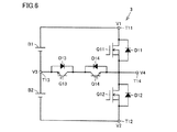
図6は、この発明の実施の形態2による無停電電源装置に含まれるインバータ3の構成を示す回路ブロック図である。無停電電源装置の全体構成は、図5で示した通りである。無停電電源装置に含まれるコンバータ2は、図1で示したコンバータである。図6において、このインバータ3は、入力端子T11〜T13(第1〜第3の出力端子)、出力端子T14(第4の出力端子)、トランジスタQ11〜Q14(第4〜第7のトランジスタ)、およびダイオードD11〜D14(第7〜第10のダイオード)を備える。
図11は、この発明の実施の形態3による無停電電源装置に含まれるインバータの構成を示す回路図であって、図6と対比される図である。図11を参照して、このインバータが図6のインバータ3と異なる点は、トランジスタQ13およびダイオードD13の並列接続体とトランジスタQ14およびダイオードD14の並列接続体とが置換されている点である。
図12は、この発明の実施の形態4による無停電電源装置に含まれるインバータの構成を示す回路図であって、図6と対比される図である。図12を参照して、このインバータが図6のインバータ3と異なる点は、トランジスタQ13,Q14のコレクタとダイオードD13,D14のカソードが切り離され、トランジスタQ13のコレクタとダイオードD14のカソードが接続され、トランジスタQ14のコレクタとダイオードD13のカソードが接続されている点である。
図13は、この発明の実施の形態5による無停電電源装置の構成を示す回路ブロック図である。図14は、図13に示したコンバータ22およびインバータ24の構成を示す回路図である。図15は、図13に示した双方向チョッパ23の構成を示す回路図である。図13〜図15において、無停電電源装置は、入力フィルタ21、コンバータ22、直流正母線L1、直流負母線L2、直流中性点母線L3、コンデンサC1,C2、双方向チョッパ23、インバータ24、および出力フィルタ25を備える。図面の簡単化のため、コンバータ22、双方向チョッパ23、およびインバータ24を制御する制御装置の図示は省略されている。
Claims (13)
- 入力端子に与えられる交流電圧を第1〜第3の直流電圧に変換してそれぞれ第1〜第3の出力端子に出力するコンバータであって、
アノードおよびカソードがそれぞれ前記入力端子および前記第1の出力端子に接続された第1のダイオードと、
アノードおよびカソードがそれぞれ前記第2の出力端子および前記入力端子に接続された第2のダイオードと、
前記第1の出力端子および前記入力端子間に接続された第1のトランジスタと、
前記入力端子および前記第2の出力端子間に接続された第2のトランジスタと、
前記入力端子および前記第3の出力端子間に接続された第1の双方向スイッチとを備え、
前記第1の直流電圧は前記第2の直流電圧よりも高く、前記第3の直流電圧は前記第1および第2の直流電圧の中間電圧であり、
前記第1の双方向スイッチは第3〜第6のダイオードおよび第3のトランジスタを含み、
前記第3および第4のダイオードのアノードはそれぞれ前記入力端子および前記第3の出力端子に接続され、それらのカソードはともに前記第3のトランジスタの第1の電極に接続され、
前記第5および第6のダイオードのカソードはそれぞれ前記入力端子および前記第3の出力端子に接続され、それらのアノードはともに前記第3のトランジスタの第2の電極に接続され、
前記第1のダイオード、前記第2のダイオード、および前記第3のトランジスタの各々はワイドバンドギャップ半導体で形成され、
前記第1のトランジスタ、前記第2のトランジスタ、および前記第3〜第6のダイオードの各々はワイドバンドギャップ半導体以外の半導体で形成され、
前記第1のトランジスタは、前記第1の出力端子の電圧が第1の定格電圧を超えた場合に前記第1の出力端子から前記入力端子に電流を流し、
前記第1の定格電圧は、前記交流電圧の正側ピーク電圧から前記第1のダイオードのしきい値電圧を減算した電圧であり、
前記第2のトランジスタは、前記第2の出力端子の電圧が第2の定格電圧よりも低下した場合に前記入力端子から前記第2の出力端子に電流を流し、
前記第2の定格電圧は、前記交流電圧の負側ピーク電圧に前記第2のダイオードのしきい値電圧を加算した電圧である、コンバータ。 - 前記交流電圧が正電圧である場合は前記第1および第3のトランジスタが交互にオンされ、
前記交流電圧が負電圧である場合は前記第2および第3のトランジスタが交互にオンされる、請求項1に記載のコンバータ。 - 前記第1〜第6のダイオードおよび前記第1〜第3のトランジスタを含む半導体モジュールを備える、請求項1に記載のコンバータ。
- 前記第1および第2のダイオードの各々の定格電流は、前記第3〜第6のダイオードおよび前記第1〜第3のトランジスタの各々の定格電流よりも大きい、請求項1に記載のコンバータ。
- 前記第1および第2のトランジスタの各々の定格電流は、前記第1〜第6のダイオードおよび前記第3のトランジスタの各々の定格電流よりも小さい、請求項4に記載のコンバータ。
- 前記ワイドバンドギャップ半導体はSiCであり、前記ワイドバンドギャップ半導体以外の半導体はSiである、請求項1に記載のコンバータ。
- 請求項1に記載のコンバータと、
それぞれ前記第1〜第3の出力端子に与えられる第1〜第3の直流電圧を3レベルの交流電圧に変換して第4の出力端子に出力するインバータとを備え、
前記インバータは、
第1および第2の電極がそれぞれ前記第1および第4の出力端子に接続された第4のトランジスタと、
第1および第2の電極がそれぞれ前記第4および第2の出力端子に接続された第5のトランジスタと、
それぞれ前記第4および第5のトランジスタに逆並列に接続された第7および第8のダイオードと、
前記第3および第4の出力端子間に接続された第2の双方向スイッチとを備え、
前記第2の双方向スイッチは、第6および第7のトランジスタと第9および第10のダイオードを含み、
前記第4のトランジスタ、前記第5のトランジスタ、前記第9のダイオード、および前記第10のダイオードの各々は前記ワイドバンドギャップ半導体で形成され、
前記第6のトランジスタ、前記第7のトランジスタ、前記第7のダイオード、および前記第8のダイオードの各々は前記ワイドバンドギャップ半導体以外の半導体で形成されている、電力変換装置。 - 前記第6および第7のトランジスタの第1の電極は互いに接続され、それらの第2の電極はそれぞれ前記第3および第4の出力端子に接続され、
前記第9および第10のダイオードはそれぞれ前記第6および第7のトランジスタに逆並列に接続され、
前記第4の出力端子に前記第1および第3の直流電圧を交互に出力する場合は、前記第7のトランジスタがオンされるとともに前記第4および第6のトランジスタが交互にオンされ、
前記第4の出力端子に前記第2および第3の直流電圧を交互に出力する場合は、前記第6のトランジスタがオンされるとともに前記第5および第7のトランジスタが交互にオンされる、請求項7に記載の電力変換装置。 - 前記第6および第7のトランジスタの第1の電極はそれぞれ前記第4および第3の出力端子に接続され、それらの第2の電極は互いに接続され、
前記第9および第10のダイオードはそれぞれ前記第6および第7のトランジスタに逆並列に接続され、
前記第4の出力端子に前記第1および第3の直流電圧を交互に出力する場合は、前記第7のトランジスタがオンされるとともに前記第4および第6のトランジスタが交互にオンされ、
前記第4の出力端子に前記第2および第3の直流電圧を交互に出力する場合は、前記第6のトランジスタがオンされるとともに前記第5および第7のトランジスタが交互にオンされる、請求項7に記載の電力変換装置。 - 前記第6および第7のトランジスタの第2の電極はそれぞれ前記第3および第4の出力端子に接続され、
前記第9および第10のダイオードのアノードはそれぞれ前記第3および第4の出力端子に接続され、それらのカソードはそれぞれ前記第7および第6のトランジスタの第1の電極に接続され、
前記第4の出力端子に前記第1および第3の直流電圧を交互に出力する場合は、前記第7のトランジスタがオンされるとともに前記第4および第6のトランジスタが交互にオンされ、
前記第4の出力端子に前記第2および第3の直流電圧を交互に出力する場合は、前記第6のトランジスタがオンされるとともに前記第5および第7のトランジスタが交互にオンされる、請求項7に記載の電力変換装置。 - 前記インバータは、前記第4〜第7のトランジスタおよび前記第7〜第10のダイオードを含む半導体モジュールを備える、請求項7に記載の電力変換装置。
- 前記第4および第5のトランジスタの各々の定格電流は、前記第6および第7のトランジスタと前記第7〜第10のダイオードの各々の定格電流よりも大きい、請求項7に記載の電力変換装置。
- 前記ワイドバンドギャップ半導体はSiCであり、前記ワイドバンドギャップ半導体以外の半導体はSiである、請求項7に記載の電力変換装置。
Applications Claiming Priority (1)
| Application Number | Priority Date | Filing Date | Title |
|---|---|---|---|
| PCT/JP2016/061757 WO2017179112A1 (ja) | 2016-04-12 | 2016-04-12 | コンバータおよびそれを用いた電力変換装置 |
Publications (2)
| Publication Number | Publication Date |
|---|---|
| JPWO2017179112A1 JPWO2017179112A1 (ja) | 2018-11-22 |
| JP6577663B2 true JP6577663B2 (ja) | 2019-09-18 |
Family
ID=60041461
Family Applications (1)
| Application Number | Title | Priority Date | Filing Date |
|---|---|---|---|
| JP2018511789A Active JP6577663B2 (ja) | 2016-04-12 | 2016-04-12 | コンバータおよびそれを用いた電力変換装置 |
Country Status (6)
| Country | Link |
|---|---|
| US (1) | US10630195B2 (ja) |
| JP (1) | JP6577663B2 (ja) |
| KR (1) | KR102208248B1 (ja) |
| CN (1) | CN109075719B (ja) |
| CA (1) | CA3019875C (ja) |
| WO (1) | WO2017179112A1 (ja) |
Cited By (1)
| Publication number | Priority date | Publication date | Assignee | Title |
|---|---|---|---|---|
| WO2021050912A1 (en) * | 2019-09-13 | 2021-03-18 | Milwaukee Electric Tool Corporation | Power converters with wide bandgap semiconductors |
Families Citing this family (2)
| Publication number | Priority date | Publication date | Assignee | Title |
|---|---|---|---|---|
| CN115315892A (zh) * | 2020-03-17 | 2022-11-08 | 华为数字能源技术有限公司 | 用于具有改进的共模性能的输入串联结构的转换器系统的ac/dc转换器级 |
| CN112968624A (zh) * | 2021-03-17 | 2021-06-15 | 山特电子(深圳)有限公司 | 双向dc-ac变换电路及其启动方法 |
Family Cites Families (10)
| Publication number | Priority date | Publication date | Assignee | Title |
|---|---|---|---|---|
| WO2006016456A1 (ja) * | 2004-08-10 | 2006-02-16 | Rohm Co., Ltd | 回路の保護方法、保護回路およびそれを利用した電源装置 |
| JP2008022625A (ja) * | 2006-07-12 | 2008-01-31 | Fuji Electric Systems Co Ltd | 交流−直流変換装置 |
| JP4642101B2 (ja) | 2008-09-11 | 2011-03-02 | 三菱電機株式会社 | 交流直流変換装置、圧縮機駆動装置、空気調和機 |
| JP5444869B2 (ja) * | 2009-06-19 | 2014-03-19 | ミツミ電機株式会社 | 出力装置 |
| JP5554140B2 (ja) * | 2009-09-04 | 2014-07-23 | 三菱電機株式会社 | 電力変換回路 |
| US9041367B2 (en) * | 2013-03-14 | 2015-05-26 | Freescale Semiconductor, Inc. | Voltage regulator with current limiter |
| US9170591B2 (en) * | 2013-09-05 | 2015-10-27 | Stmicroelectronics International N.V. | Low drop-out regulator with a current control circuit |
| US10116228B2 (en) | 2014-08-29 | 2018-10-30 | Toshiba Mitsubishi-Electric Industrial Systems Corporation | Converter and power conversion device manufactured using the same |
| US9843270B2 (en) * | 2015-01-13 | 2017-12-12 | Hamilton Sundstrand Corporation | Phase leg arrangements for multilevel active rectifiers |
| DE102015204021B4 (de) * | 2015-03-05 | 2017-04-06 | Dialog Semiconductor (Uk) Limited | Dynamische Strombegrenzungsschaltung |
-
2016
- 2016-04-12 CN CN201680084547.1A patent/CN109075719B/zh active Active
- 2016-04-12 CA CA3019875A patent/CA3019875C/en active Active
- 2016-04-12 US US16/080,838 patent/US10630195B2/en active Active
- 2016-04-12 JP JP2018511789A patent/JP6577663B2/ja active Active
- 2016-04-12 KR KR1020187031946A patent/KR102208248B1/ko active IP Right Grant
- 2016-04-12 WO PCT/JP2016/061757 patent/WO2017179112A1/ja active Application Filing
Cited By (2)
| Publication number | Priority date | Publication date | Assignee | Title |
|---|---|---|---|---|
| WO2021050912A1 (en) * | 2019-09-13 | 2021-03-18 | Milwaukee Electric Tool Corporation | Power converters with wide bandgap semiconductors |
| US11923716B2 (en) | 2019-09-13 | 2024-03-05 | Milwaukee Electric Tool Corporation | Power converters with wide bandgap semiconductors |
Also Published As
| Publication number | Publication date |
|---|---|
| US20190058414A1 (en) | 2019-02-21 |
| KR102208248B1 (ko) | 2021-01-26 |
| CA3019875C (en) | 2021-06-22 |
| CN109075719B (zh) | 2021-02-19 |
| KR20180132114A (ko) | 2018-12-11 |
| CA3019875A1 (en) | 2017-10-19 |
| CN109075719A (zh) | 2018-12-21 |
| JPWO2017179112A1 (ja) | 2018-11-22 |
| US10630195B2 (en) | 2020-04-21 |
| WO2017179112A1 (ja) | 2017-10-19 |
Similar Documents
| Publication | Publication Date | Title |
|---|---|---|
| US9083274B2 (en) | Power stage precharging and dynamic braking apparatus for multilevel inverter | |
| US10038392B2 (en) | Inverter | |
| JP6206502B2 (ja) | 電力変換装置及び電力変換方法 | |
| KR102061988B1 (ko) | 무정전 전원 장치 | |
| US10116228B2 (en) | Converter and power conversion device manufactured using the same | |
| JP6378828B2 (ja) | コンバータおよびそれを用いた電力変換装置 | |
| JPWO2018043367A1 (ja) | 電力変換システム | |
| EP3813239B1 (en) | Self-feeding circuit and power conversion device | |
| JP6577663B2 (ja) | コンバータおよびそれを用いた電力変換装置 | |
| JP5362657B2 (ja) | 電力変換装置 | |
| EP1519476B1 (en) | Power controlling apparatus | |
| US9300208B2 (en) | Power converter with switched current supply control element | |
| JP2021191184A (ja) | Dc/dc変換装置 |
Legal Events
| Date | Code | Title | Description |
|---|---|---|---|
| A621 | Written request for application examination |
Free format text: JAPANESE INTERMEDIATE CODE: A621 Effective date: 20180713 |
|
| A131 | Notification of reasons for refusal |
Free format text: JAPANESE INTERMEDIATE CODE: A131 Effective date: 20190514 |
|
| A521 | Request for written amendment filed |
Free format text: JAPANESE INTERMEDIATE CODE: A523 Effective date: 20190710 |
|
| TRDD | Decision of grant or rejection written | ||
| A01 | Written decision to grant a patent or to grant a registration (utility model) |
Free format text: JAPANESE INTERMEDIATE CODE: A01 Effective date: 20190820 |
|
| A61 | First payment of annual fees (during grant procedure) |
Free format text: JAPANESE INTERMEDIATE CODE: A61 Effective date: 20190822 |
|
| R150 | Certificate of patent or registration of utility model |
Ref document number: 6577663 Country of ref document: JP Free format text: JAPANESE INTERMEDIATE CODE: R150 |
|
| R250 | Receipt of annual fees |
Free format text: JAPANESE INTERMEDIATE CODE: R250 |
|
| R250 | Receipt of annual fees |
Free format text: JAPANESE INTERMEDIATE CODE: R250 |