JP6576208B2 - Image forming apparatus - Google Patents
Image forming apparatus Download PDFInfo
- Publication number
- JP6576208B2 JP6576208B2 JP2015209870A JP2015209870A JP6576208B2 JP 6576208 B2 JP6576208 B2 JP 6576208B2 JP 2015209870 A JP2015209870 A JP 2015209870A JP 2015209870 A JP2015209870 A JP 2015209870A JP 6576208 B2 JP6576208 B2 JP 6576208B2
- Authority
- JP
- Japan
- Prior art keywords
- bottle
- toner
- gear
- toner bottle
- image forming
- Prior art date
- Legal status (The legal status is an assumption and is not a legal conclusion. Google has not performed a legal analysis and makes no representation as to the accuracy of the status listed.)
- Active
Links
Images


Classifications
-
- G—PHYSICS
- G03—PHOTOGRAPHY; CINEMATOGRAPHY; ANALOGOUS TECHNIQUES USING WAVES OTHER THAN OPTICAL WAVES; ELECTROGRAPHY; HOLOGRAPHY
- G03G—ELECTROGRAPHY; ELECTROPHOTOGRAPHY; MAGNETOGRAPHY
- G03G15/00—Apparatus for electrographic processes using a charge pattern
- G03G15/06—Apparatus for electrographic processes using a charge pattern for developing
- G03G15/08—Apparatus for electrographic processes using a charge pattern for developing using a solid developer, e.g. powder developer
- G03G15/0822—Arrangements for preparing, mixing, supplying or dispensing developer
- G03G15/0877—Arrangements for metering and dispensing developer from a developer cartridge into the development unit
- G03G15/0879—Arrangements for metering and dispensing developer from a developer cartridge into the development unit for dispensing developer from a developer cartridge not directly attached to the development unit
-
- G—PHYSICS
- G03—PHOTOGRAPHY; CINEMATOGRAPHY; ANALOGOUS TECHNIQUES USING WAVES OTHER THAN OPTICAL WAVES; ELECTROGRAPHY; HOLOGRAPHY
- G03G—ELECTROGRAPHY; ELECTROPHOTOGRAPHY; MAGNETOGRAPHY
- G03G15/00—Apparatus for electrographic processes using a charge pattern
- G03G15/06—Apparatus for electrographic processes using a charge pattern for developing
- G03G15/08—Apparatus for electrographic processes using a charge pattern for developing using a solid developer, e.g. powder developer
- G03G15/0822—Arrangements for preparing, mixing, supplying or dispensing developer
- G03G15/0865—Arrangements for supplying new developer
- G03G15/0867—Arrangements for supplying new developer cylindrical developer cartridges, e.g. toner bottles for the developer replenishing opening
- G03G15/087—Developer cartridges having a longitudinal rotational axis, around which at least one part is rotated when mounting or using the cartridge
- G03G15/0872—Developer cartridges having a longitudinal rotational axis, around which at least one part is rotated when mounting or using the cartridge the developer cartridges being generally horizontally mounted parallel to its longitudinal rotational axis
-
- G—PHYSICS
- G03—PHOTOGRAPHY; CINEMATOGRAPHY; ANALOGOUS TECHNIQUES USING WAVES OTHER THAN OPTICAL WAVES; ELECTROGRAPHY; HOLOGRAPHY
- G03G—ELECTROGRAPHY; ELECTROPHOTOGRAPHY; MAGNETOGRAPHY
- G03G15/00—Apparatus for electrographic processes using a charge pattern
- G03G15/06—Apparatus for electrographic processes using a charge pattern for developing
- G03G15/08—Apparatus for electrographic processes using a charge pattern for developing using a solid developer, e.g. powder developer
- G03G15/0822—Arrangements for preparing, mixing, supplying or dispensing developer
- G03G15/0863—Arrangements for preparing, mixing, supplying or dispensing developer provided with identifying means or means for storing process- or use parameters, e.g. an electronic memory
-
- G—PHYSICS
- G03—PHOTOGRAPHY; CINEMATOGRAPHY; ANALOGOUS TECHNIQUES USING WAVES OTHER THAN OPTICAL WAVES; ELECTROGRAPHY; HOLOGRAPHY
- G03G—ELECTROGRAPHY; ELECTROPHOTOGRAPHY; MAGNETOGRAPHY
- G03G15/00—Apparatus for electrographic processes using a charge pattern
- G03G15/06—Apparatus for electrographic processes using a charge pattern for developing
- G03G15/08—Apparatus for electrographic processes using a charge pattern for developing using a solid developer, e.g. powder developer
- G03G15/0822—Arrangements for preparing, mixing, supplying or dispensing developer
- G03G15/0865—Arrangements for supplying new developer
- G03G15/0867—Arrangements for supplying new developer cylindrical developer cartridges, e.g. toner bottles for the developer replenishing opening
- G03G15/0868—Toner cartridges fulfilling a continuous function within the electrographic apparatus during the use of the supplied developer material, e.g. toner discharge on demand, storing residual toner, acting as an active closure for the developer replenishing opening
-
- G—PHYSICS
- G03—PHOTOGRAPHY; CINEMATOGRAPHY; ANALOGOUS TECHNIQUES USING WAVES OTHER THAN OPTICAL WAVES; ELECTROGRAPHY; HOLOGRAPHY
- G03G—ELECTROGRAPHY; ELECTROPHOTOGRAPHY; MAGNETOGRAPHY
- G03G15/00—Apparatus for electrographic processes using a charge pattern
- G03G15/06—Apparatus for electrographic processes using a charge pattern for developing
- G03G15/08—Apparatus for electrographic processes using a charge pattern for developing using a solid developer, e.g. powder developer
- G03G15/0822—Arrangements for preparing, mixing, supplying or dispensing developer
- G03G15/0865—Arrangements for supplying new developer
- G03G15/0867—Arrangements for supplying new developer cylindrical developer cartridges, e.g. toner bottles for the developer replenishing opening
- G03G15/087—Developer cartridges having a longitudinal rotational axis, around which at least one part is rotated when mounting or using the cartridge
-
- G—PHYSICS
- G03—PHOTOGRAPHY; CINEMATOGRAPHY; ANALOGOUS TECHNIQUES USING WAVES OTHER THAN OPTICAL WAVES; ELECTROGRAPHY; HOLOGRAPHY
- G03G—ELECTROGRAPHY; ELECTROPHOTOGRAPHY; MAGNETOGRAPHY
- G03G15/00—Apparatus for electrographic processes using a charge pattern
- G03G15/06—Apparatus for electrographic processes using a charge pattern for developing
- G03G15/08—Apparatus for electrographic processes using a charge pattern for developing using a solid developer, e.g. powder developer
- G03G15/0822—Arrangements for preparing, mixing, supplying or dispensing developer
- G03G15/0877—Arrangements for metering and dispensing developer from a developer cartridge into the development unit
- G03G15/0881—Sealing of developer cartridges
- G03G15/0886—Sealing of developer cartridges by mechanical means, e.g. shutter, plug
-
- G—PHYSICS
- G03—PHOTOGRAPHY; CINEMATOGRAPHY; ANALOGOUS TECHNIQUES USING WAVES OTHER THAN OPTICAL WAVES; ELECTROGRAPHY; HOLOGRAPHY
- G03G—ELECTROGRAPHY; ELECTROPHOTOGRAPHY; MAGNETOGRAPHY
- G03G15/00—Apparatus for electrographic processes using a charge pattern
- G03G15/50—Machine control of apparatus for electrographic processes using a charge pattern, e.g. regulating differents parts of the machine, multimode copiers, microprocessor control
- G03G15/5008—Driving control for rotary photosensitive medium, e.g. speed control, stop position control
-
- G—PHYSICS
- G03—PHOTOGRAPHY; CINEMATOGRAPHY; ANALOGOUS TECHNIQUES USING WAVES OTHER THAN OPTICAL WAVES; ELECTROGRAPHY; HOLOGRAPHY
- G03G—ELECTROGRAPHY; ELECTROPHOTOGRAPHY; MAGNETOGRAPHY
- G03G15/00—Apparatus for electrographic processes using a charge pattern
- G03G15/55—Self-diagnostics; Malfunction or lifetime display
- G03G15/553—Monitoring or warning means for exhaustion or lifetime end of consumables, e.g. indication of insufficient copy sheet quantity for a job
- G03G15/556—Monitoring or warning means for exhaustion or lifetime end of consumables, e.g. indication of insufficient copy sheet quantity for a job for toner consumption, e.g. pixel counting, toner coverage detection or toner density measurement
-
- G—PHYSICS
- G03—PHOTOGRAPHY; CINEMATOGRAPHY; ANALOGOUS TECHNIQUES USING WAVES OTHER THAN OPTICAL WAVES; ELECTROGRAPHY; HOLOGRAPHY
- G03G—ELECTROGRAPHY; ELECTROPHOTOGRAPHY; MAGNETOGRAPHY
- G03G21/00—Arrangements not provided for by groups G03G13/00 - G03G19/00, e.g. cleaning, elimination of residual charge
- G03G21/14—Electronic sequencing control
- G03G21/145—Electronic sequencing control wherein control pulses are generated by the mechanical movement of parts of the machine, e.g. the photoconductor
-
- G—PHYSICS
- G03—PHOTOGRAPHY; CINEMATOGRAPHY; ANALOGOUS TECHNIQUES USING WAVES OTHER THAN OPTICAL WAVES; ELECTROGRAPHY; HOLOGRAPHY
- G03G—ELECTROGRAPHY; ELECTROPHOTOGRAPHY; MAGNETOGRAPHY
- G03G21/00—Arrangements not provided for by groups G03G13/00 - G03G19/00, e.g. cleaning, elimination of residual charge
- G03G21/16—Mechanical means for facilitating the maintenance of the apparatus, e.g. modular arrangements
- G03G21/18—Mechanical means for facilitating the maintenance of the apparatus, e.g. modular arrangements using a processing cartridge, whereby the process cartridge comprises at least two image processing means in a single unit
- G03G21/1839—Means for handling the process cartridge in the apparatus body
- G03G21/1857—Means for handling the process cartridge in the apparatus body for transmitting mechanical drive power to the process cartridge, drive mechanisms, gears, couplings, braking mechanisms
Description
本発明は、現像剤を収容する収容容器を備えた画像形成装置に関する。 The present invention relates to an image forming apparatus including a storage container that stores a developer.
現像剤を収容した収容容器(トナーボトル)を備えた画像形成装置として、トナーボトルの回転動作に伴ってトナーボトルの排出口からトナーが排出され、現像装置にトナーが補給される構成が知られている。このようなトナーボトルを用いる場合、トナーの排出量を高精度に制御すべく、トナーボトルの回転速度を高精度で制御可能であることが好ましい。 As an image forming apparatus provided with a container (toner bottle) containing a developer, a configuration is known in which toner is discharged from a discharge port of a toner bottle as the toner bottle rotates and toner is supplied to the developing device. ing. When such a toner bottle is used, it is preferable that the rotation speed of the toner bottle can be controlled with high accuracy in order to control the discharged amount of toner with high accuracy.
このような構成として、例えば、ボトルの回転に伴って駆動されるポンプ部を有するトナーボトルと、トナーボトルを回転させる駆動モータと、駆動モータの回転速度を制御するモータ制御用ICと、を備えた画像形成装置が提案されている(特許文献1参照)。この画像形成装置には、トナーボトルの回転速度を計測可能なフラグ式の回転検知センサが設けられている。そして、モータ制御用ICは、回転検知センサからのフィードバック信号に基づいて、トナーボトルの回転速度を予め定められた目標値に近付けるように駆動モータの出力を制御する。 As such a configuration, for example, a toner bottle having a pump unit driven as the bottle rotates, a drive motor that rotates the toner bottle, and a motor control IC that controls the rotation speed of the drive motor are provided. An image forming apparatus has been proposed (see Patent Document 1). This image forming apparatus is provided with a flag type rotation detection sensor capable of measuring the rotation speed of the toner bottle. The motor control IC controls the output of the drive motor based on the feedback signal from the rotation detection sensor so that the rotation speed of the toner bottle approaches a predetermined target value.
ところで、排出口を閉じられた状態の収容容器を画像形成装置本体の内部に収納したまま出荷して、装置本体の設置時に自動で排出口を開ける構成とした画像形成装置が考えられる。例えば、現像剤収容容器の排出口を開閉可能な開閉部材と、駆動モータ(駆動装置)から収容容器に伝達される駆動力の一部を利用して開閉部材を移動させる移動機構とを設ける構成が挙げられる。そして、このような構成において、上記特許文献1に記載のように駆動モータの出力をフィードバック制御することが考えられる。即ち、駆動モータの駆動により開閉部材を移動させて排出口を開ける初期動作と、初期動作の後に収容容器を回転させて現像剤を排出する現像剤排出動作とを、一連のフィードバック制御によって実行することが考えられる。 By the way, there can be considered an image forming apparatus in which a container with a discharge port closed is shipped while being stored inside the main body of the image forming apparatus, and the discharge port is automatically opened when the apparatus main body is installed. For example, a configuration in which an opening / closing member capable of opening / closing the discharge port of the developer container and a moving mechanism for moving the opening / closing member using a part of the driving force transmitted from the drive motor (driving device) to the container is provided. Is mentioned. In such a configuration, it is conceivable to feedback-control the output of the drive motor as described in Patent Document 1. That is, an initial operation for opening the discharge port by moving the opening / closing member by driving the drive motor and a developer discharging operation for discharging the developer by rotating the container after the initial operation are performed by a series of feedback control. It is possible.
しかしながら、このように収容容器を駆動する駆動力の一部を利用して排出口を開ける構成の場合、初期動作時と初期動作の後とで駆動モータの負荷トルクが異なる場合がある。この場合、負荷トルクの差によって駆動モータの回転速度が目標値に収束するまでの時間が長くなり、現像剤排出動作における収容容器の回転速度が不安定となって、現像剤の排出量のばらつきが大きくなる可能性がある。また、駆動モータの回転速度が変動することにより、駆動モータの振動が例えば装置本体の部品の共振周波数帯に含まれると、装置の振動が大きくなる場合がある。この場合には、例えば、初期動作に並行して行われる装置本体の初期化作業(現像装置の調整作業など)に影響を及ぼす可能性がある。 However, in the case where the discharge opening is opened by utilizing a part of the driving force for driving the container as described above, the load torque of the driving motor may be different between the initial operation and the initial operation. In this case, due to the difference in load torque, the time until the rotational speed of the drive motor converges to the target value becomes longer, the rotational speed of the container in the developer discharging operation becomes unstable, and the developer discharge amount varies. May become large. Further, when the rotational speed of the drive motor varies, the vibration of the device may increase if the vibration of the drive motor is included in, for example, the resonance frequency band of the component of the device body. In this case, for example, there is a possibility of affecting the initialization operation (development device adjustment operation, etc.) of the apparatus main body performed in parallel with the initial operation.
そこで本発明は、収容容器を回転させる駆動装置により開閉部材を移動させて排出口を開ける構成において、開閉部材を開けた後に収容容器の回転が不安定になることを防ぐことが可能な画像形成装置を提供することを目的とする。 Accordingly, the present invention provides an image formation that can prevent the rotation of the storage container from becoming unstable after the opening / closing member is opened in a configuration in which the opening / closing member is opened by moving the opening / closing member by a driving device that rotates the storage container. An object is to provide an apparatus.
本発明の一態様は、トナーを用いて記録材に画像を形成する画像形成装置であって、装置本体と、駆動装置と、制御手段と、前記装置本体の装着部に装着可能であり、トナーを収容し、収容されたトナーを排出する排出部を有し、前記駆動装置から供給される駆動力により回転駆動されるトナーボトルと、前記トナーボトルが所定回数回転したことに関する情報を検知する検知部と、前記トナーボトルに設けられ、前記排出部が遮蔽される遮蔽位置と前記排出部が開放される開放位置との間で移動可能なシャッター部材と、前記トナーボトルに設けられ、前記装着部に前記トナーボトルが装着された状態で前記駆動力が入力されるボトルギヤと、前記装置本体に設けられ、前記装着部に前記トナーボトルが装着された状態で前記ボトルギヤの回転動作に伴って前記シャッター部材を前記遮蔽位置から前記開放位置に移動させるための移動機構と、前記トナーボトルに設けられ、前記装着部に前記トナーボトルが装着された状態で前記ボトルギヤの回転動作に伴って前記排出部から所定量のトナーを排出するための排出機構と、を備え、前記制御手段は、前記ボトルギヤに前記駆動力が入力されてから、前記トナーボトルが前記所定回数回転したことに関する情報を前記検知部が検知するまでの間の、前記ボトルギヤに入力される前記駆動力の大きさよりも、前記ボトルギヤに前記駆動力が入力されてから、前記トナーボトルが前記所定回数回転したことに関する情報を前記検知部が検知した後、前記排出機構が前記排出部から前記所定量のトナーを最初に排出する際の、前記ボトルギヤに入力される前記駆動力の大きさの方が小さくなるように、前記駆動装置を制御することを特徴とする画像形成装置である。
本発明の他の態様は、トナーを用いて記録材に画像を形成する画像形成装置であって、装置本体と、駆動装置と、制御手段と、前記装置本体の装着部に装着可能であり、トナーを収容し、収容されたトナーを排出する排出部を有し、前記駆動装置から供給される駆動力により回転駆動されるトナーボトルと、前記トナーボトルの回転に関する情報を検知する検知部と、前記トナーボトルに設けられ、前記排出部が遮蔽される遮蔽位置と前記排出部が開放される開放位置との間で移動可能なシャッター部材と、前記トナーボトルに設けられ、前記装着部に前記トナーボトルが装着された状態で前記駆動力が入力されるボトルギヤと、前記装置本体に設けられ、前記装着部に前記トナーボトルが装着された状態で前記ボトルギヤの回転動作に伴って前記シャッター部材を前記遮蔽位置から前記開放位置に移動させるための移動機構と、前記トナーボトルに設けられ、前記装着部に前記トナーボトルが装着された状態で前記ボトルギヤの回転動作に伴って前記排出部から所定量のトナーを排出するための排出機構と、を備え、前記制御手段は、前記ボトルギヤに前記駆動力が入力されてから前記検知部が前記トナーボトルの回転に関する情報を所定回数検知するまでの間の、前記ボトルギヤに入力される前記駆動力の大きさよりも、前記ボトルギヤに前記駆動力が入力されてから前記検知部が前記トナーボトルの回転に関する情報を前記所定回数検知した後、前記排出機構が前記排出部から前記所定量のトナーを最初に排出する際の、前記ボトルギヤに入力される前記駆動力の大きさの方が小さくなるように前記駆動装置を制御することを特徴とする画像形成装置である。
本発明のさらに他の態様は、トナーを用いて記録材に画像を形成する画像形成装置であって、装置本体と、駆動装置と、制御手段と、前記装置本体の装着部に装着可能であり、トナーを収容し、収容されたトナーを排出する排出部を有し、前記駆動装置から供給される駆動力により回転駆動されるトナーボトルと、前記トナーボトルに設けられ、前記排出部が遮蔽される遮蔽位置と前記排出部が開放される開放位置との間で移動可能なシャッター部材と、前記トナーボトルに設けられ、前記装着部に前記トナーボトルが装着された状態で前記駆動力が入力されるボトルギヤと、前記装置本体に設けられ、前記装着部に前記トナーボトルが装着された状態で前記ボトルギヤの回転動作に伴って前記シャッター部材を前記遮蔽位置から前記開放位置に移動させるための移動機構と、前記トナーボトルに設けられ、前記装着部に前記トナーボトルが装着された状態で前記ボトルギヤの回転動作に伴って前記排出部から所定量のトナーを排出するための排出機構と、を備え、前記制御手段は、前記移動機構が前記シャッター部材を前記遮蔽位置から前記開放位置に移動させるまでの間の、前記ボトルギヤに入力される前記駆動力の大きさよりも、前記移動機構が前記シャッター部材を前記遮蔽位置から前記開放位置に移動させた後、前記排出機構が前記排出部から前記所定量のトナーを最初に排出する際の、前記ボトルギヤに入力される前記駆動力の大きさの方が小さくなるように前記駆動装置を制御することを特徴とする画像形成装置である。
One embodiment of the present invention is an image forming apparatus that forms an image on a recording material using toner, and can be mounted on the apparatus main body, a driving device, a control unit, and a mounting portion of the apparatus main body. A toner bottle that rotates and is driven by a driving force supplied from the driving device, and a detection that detects information related to the rotation of the toner bottle a predetermined number of times. , A shutter member provided in the toner bottle, movable between a shielding position where the discharge part is shielded and an open position where the discharge part is opened, and provided in the toner bottle, and the mounting part A bottle gear to which the driving force is input when the toner bottle is attached to the apparatus main body, and the bottle gear with the toner bottle attached to the attachment portion. A movement mechanism for moving the shutter member from the shielding position to the open position in accordance with a rolling operation, and a rotation operation of the bottle gear provided in the toner bottle and with the toner bottle mounted on the mounting portion A discharge mechanism for discharging a predetermined amount of toner from the discharge unit, and the control means has rotated the predetermined number of times after the driving force is input to the bottle gear. The toner bottle has rotated a predetermined number of times after the driving force is input to the bottle gear rather than the magnitude of the driving force input to the bottle gear until the detection unit detects information about After the detection unit detects the information on the bottle, the discharge mechanism first discharges the predetermined amount of toner from the discharge unit. As towards the magnitude of the driving force input to the Ya decreases, an image forming apparatus and controls the driving device.
Another aspect of the present invention is an image forming apparatus that forms an image on a recording material using toner, and can be mounted on an apparatus main body, a driving device, a control unit, and a mounting portion of the apparatus main body. A toner bottle that contains toner and has a discharge unit that discharges the contained toner; the toner bottle that is rotationally driven by a driving force supplied from the driving device; and a detection unit that detects information related to rotation of the toner bottle; A shutter member provided on the toner bottle and movable between a shielding position where the discharge part is shielded and an open position where the discharge part is opened; A bottle gear to which the driving force is input in a state in which the bottle is mounted, and a rotational movement of the bottle gear provided in the apparatus main body and in the state in which the toner bottle is mounted in the mounting portion. A moving mechanism for moving the shutter member from the shielding position to the open position and the toner bottle are provided in the toner bottle, and the discharge is accompanied by a rotation operation of the bottle gear in a state where the toner bottle is attached to the attachment portion. A discharge mechanism for discharging a predetermined amount of toner from the unit, and the control unit detects information related to rotation of the toner bottle a predetermined number of times after the driving force is input to the bottle gear. Until the detection unit detects information about rotation of the toner bottle a predetermined number of times after the driving force is input to the bottle gear, rather than the magnitude of the driving force input to the bottle gear. The magnitude of the driving force input to the bottle gear when the discharge mechanism first discharges the predetermined amount of toner from the discharge portion. An image forming apparatus and controls the driving device so as to reduce.
Still another embodiment of the present invention is an image forming apparatus that forms an image on a recording material using toner, and can be mounted on the apparatus main body, a driving device, a control unit, and a mounting portion of the apparatus main body. A toner bottle that contains toner and discharges the contained toner, and is provided in the toner bottle that is rotationally driven by a driving force supplied from the driving device; and the discharge part is shielded. A shutter member movable between a shielding position and an open position where the discharge portion is opened; and the toner bottle is provided with the driving force input in a state where the toner bottle is attached to the attachment portion. A bottle gear that is provided in the apparatus main body, and the shutter member is moved from the shielding position to the open position in accordance with a rotation operation of the bottle gear in a state where the toner bottle is mounted in the mounting portion. A moving mechanism for moving the toner bottle to the toner bottle, and for discharging a predetermined amount of toner from the discharge portion in accordance with the rotation operation of the bottle gear in a state where the toner bottle is mounted on the mounting portion. A discharging mechanism, and the control means is more than the magnitude of the driving force input to the bottle gear until the moving mechanism moves the shutter member from the shielding position to the open position. The driving force input to the bottle gear when the discharge mechanism first discharges the predetermined amount of toner from the discharge portion after the movement mechanism moves the shutter member from the shielding position to the open position. The image forming apparatus is characterized in that the driving device is controlled so that the size of the image becomes smaller.
本発明によれば、開閉部材を開けた後に収容容器の回転が不安定になることを防ぐことができる。 According to the present invention, it is possible to prevent the rotation of the container from becoming unstable after opening the opening / closing member.
以下、図面に沿って本発明の実施形態に係る画像形成装置100について説明する。なお、画像形成装置100において、トナーボトルTY〜TKの挿入方向側(図1の紙面奥側)を「奥側」とし、その反対側(図1の紙面手前側)を「手前側」とする。また、装置奥側を向いた視点(図1の視点)を基準に各部材の上下左右の方向を表すものとする。
Hereinafter, an
[画像形成装置]
画像形成装置100は、図1に示すように、電子写真方式を用いてトナー像を形成する4つの画像形成部PY,PM,PC,PKが中間転写ベルト7に沿って配置された所謂中間転写タンデム方式のカラー画像形成装置である。画像形成部PY,PM,PC,PKのそれぞれは、イエロー(Y)、シアン(M)、マゼンタ(C)、又はブラック(K)のトナー色に対応している。画像形成装置100の装置本体101には、画像形成部PY,PM,PC,PK及び中間転写ベルト7の他に、収納庫10、給送ローラ61、レジストローラ62、2次転写部T2、定着装置13、排紙トレイ63、及びCPU50等が設けられている。また、画像形成部PY,PM,PC,PKのそれぞれに対応する色のトナーを収容したトナーボトルTY,TM,TC,TKが、装置本体101に対して着脱自在に設けられている。
[Image forming apparatus]
As shown in FIG. 1, the
収納庫10には、記録材S(例えばプリンタ用紙、OHPシートなどのシート材)が積載された状態で収納されている。給送ローラ61は摩擦分離方式のローラ対であって、後述する画像形成プロセスに並行して記録材Sを1枚ずつ分離してレジストローラ62へ向けて搬送する。レジストローラ62は、記録材Sの斜行を補正すると共に、2次転写部T2におけるトナー像の転写タイミングに合わせて記録材Sを2次転写部T2へ向けて搬送する。
In the
2次転写部T2は、2次転写内ローラ8に巻き掛けられた中間転写ベルト7と2次転写外ローラ9との間のニップ部として形成されている。対向するローラ対である2次転写内ローラ8及び2次転写外ローラ9には、所定の加圧力と静電的負荷バイアスとが付与されている。2次転写部T2は、レジストローラ62から搬送された記録材Sを挟持して、加圧力及び静電的負荷バイアスによって中間転写ベルト7に担持されたトナー像を記録材Sに吸着(二次転写)させるように構成されている。
The secondary transfer portion T <b> 2 is formed as a nip portion between the intermediate transfer belt 7 wound around the secondary transfer
定着装置13は、対向する一対の定着ローラ13a,13bと、これら定着ローラ13a,13bの間に形成されたニップ部に圧力を与える付勢手段と、記録材Sのトナー像に熱量を供給するヒータ(熱源)とを備える。定着ローラ13a,13bは、画像形成プロセスの進行に合わせて適宜温度管理されており、2次転写部T2を通過した記録材Sが定着装置13のローラ対に挟持されると、トナー像が溶融して記録材Sに固着する。画像を定着させられた記録材Sは、片面印刷の場合は排紙トレイ63に排出され、両面印刷を行う場合は不図示の反転搬送装置を介して再び2次転写部T2へと搬送され、裏面に画像を形成される。
The fixing
[画像形成部]
次に、図1に基づいて画像形成部PY,PM,PC,PKの構成及び画像形成部PY,PM,PC,PKにおけるトナー像の形成過程(画像形成プロセス)について説明する。これら画像形成部PY,PM,PC,PKは、中間転写ベルト7の搬送方向(矢印R)に沿ってイエロー(PY)、マゼンタ(PM)、シアン(PC)、及びブラック(PK)の順に配置されている。ただし、色数は4色に限定されるものではなく、並び順もこの限りではない。
[Image forming unit]
Next, the configuration of the image forming units PY, PM, PC, and PK and the toner image forming process (image forming process) in the image forming units PY, PM, PC, and PK will be described with reference to FIG. These image forming portions PY, PM, PC, and PK are arranged in the order of yellow (PY), magenta (PM), cyan (PC), and black (PK) along the conveyance direction (arrow R) of the intermediate transfer belt 7. Has been. However, the number of colors is not limited to four, and the arrangement order is not limited to this.
なお、以下の説明において、イエローのトナーを用いる画像形成部PYについて説明するが、その他の画像形成部PM,PC,PKもトナー色の違いを除いて同様に構成されている。そのため、画像形成部毎に設けられる部材の符号には末尾に「M」、「C」、又は「K」を付して説明を省略する。 In the following description, the image forming unit PY using yellow toner will be described, but the other image forming units PM, PC, and PK are configured similarly except for the difference in toner color. Therefore, “M”, “C”, or “K” is appended to the reference numerals of the members provided for each image forming unit, and the description thereof is omitted.
画像形成部PYは、感光ドラム1Y、帯電装置2Y、露光装置3Y、現像装置15Y、1次転写ローラ5Y、及び感光体クリーナ6Y等を有している。画像形成部PYは、装置本体101のCPU50から送信される画像形成指令及び画像情報に基づいて画像形成プロセスを開始する。
The image forming unit PY includes a
像担持体としての感光ドラム1Yは、図示しない現像駆動装置によって、中間転写ベルト7の搬送方向(R)に沿って回転駆動され、表面を帯電装置2Yによって一様に帯電される。感光ドラム1Yには、露光装置3Yから回折手段を経由したレーザー光が画像情報に基づいて照射され、レーザー光によって感光ドラム1Yの表面電荷が除電されて静電潜像が形成される。
The
現像装置15Yは、トナーを含む現像剤を収容する現像容器16Yと、現像剤を担持して回転する現像スリーブとを有する。現像スリーブと感光ドラム1Yとの間には現像バイアス電界が形成されており、現像スリーブに担持された現像剤のトナーが静電的に付勢されて感光ドラム1Yの表面に移動することで、静電潜像がイエローのトナー像として顕在化(現像)される。なお、現像容器16Yの内部(現像装置内部)には、現像容器16Yに収容された現像剤のトナー濃度(現像剤に対するトナーの重量比;T/D比)を計測可能なトナー濃度検知手段としてのトナー濃度センサ19Yが設けられている。
The developing
ここで、本実施形態における現像剤は、磁性キャリアと非磁性トナーとを含む二成分現像剤である。初期状態の現像装置15Yには、所定の割合で混合されたキャリア及びトナーを含む初期現像剤が封入され、トナーボトルTYには、イエロートナーが封入されている。なお、現像剤として磁性トナー又は非磁性トナーのみを用いる一成分現像剤を用いる構成であってもよい。また、トナー以外の成分をトナーボトルに封入してもよく、例えばトナーとキャリアとをトナーリッチな所定の割合で混合した現像剤を封入する構成であってもよい。
Here, the developer in the present embodiment is a two-component developer including a magnetic carrier and a nonmagnetic toner. An initial developer containing carrier and toner mixed at a predetermined ratio is sealed in the developing
1次転写ローラ5Yは、中間転写ベルト7を挟んで感光ドラム1Yに対向配置され、感光ドラム1Yとの間のニップ部として1次転写部T1Yを形成している。感光ドラム1Yに担持されたトナー像は、1次転写ローラ5Yにより1次転写部T1Yに与えられた加圧力及び静電的負荷バイアスによって中間転写ベルト7へと移動し、中間転写ベルト7にトナー像が1次転写される。なお、1次転写部T1Yを通過して感光ドラム1Yに残留した転写残トナーは感光体クリーナ6Yによって回収され、感光体クリーナ6Yを通過した部分の感光ドラム1Yの表面は再び帯電可能な状態となる。
The
中間転写体としての中間転写ベルト7は図示しないベルトフレームに支持されると共に、2次転写内ローラ8と、テンションローラ17と、2次転写上流ローラ18とに巻き掛けられた無端状のベルトである。2次転写内ローラ8は中間転写ベルト7への駆動伝達手段を兼ねており、不図示の駆動手段に駆動されて回転して中間転写ベルト7を矢印Rに示す方向に駆動する。
The intermediate transfer belt 7 as an intermediate transfer member is supported by a belt frame (not shown) and is an endless belt wound around a secondary transfer
上述した画像形成プロセスは他の画像形成部PM,PC,PKにおいても並行して進められ、感光ドラム1M,1C,1Kの表面にマゼンタ、シアン、又はブラックのトナー像がそれぞれ形成される。これらのトナー像は1次転写部T1M,T1C,T1Kにおいてイエローのトナー像に重ね合わせるように転写され、中間転写ベルト7の表面にフルカラーのトナー像が形成される。中間転写ベルト7は、上述した通り、2次転写部T2においてフルカラーのトナー像を記録材Sに転写可能に構成される。
The above-described image forming process proceeds in parallel in the other image forming portions PM, PC, and PK, and magenta, cyan, or black toner images are formed on the surfaces of the
なお、1次転写部T1Kの下流側には、中間転写ベルト7の表面に転写されたトナーパッチの濃度を計測可能な濃度検知手段としての光学式の濃度検出センサ29が配置されている。また、2次転写部T2を通過して中間転写ベルト7に残留した転写残トナーは転写クリーナ装置11によって回収される。中間転写ベルト7の表面は、転写クリーナ装置11を通過すると、再びトナー像を担持可能な状態となる。
An optical
[トナーボトル]
続いて、現像剤を収容する収容容器としてのトナーボトルTY,TM,TC,TKについて説明する。なお、イエローのトナーを収容したトナーボトルTYについて説明するが、シアン、マゼンタ、及びブラックのトナーボトルTM,TC,TKについても同様に構成されているため、対応する部材の符号末尾にM,C,Kのいずれかを付して説明を省略する。
[Toner bottle]
Next, toner bottles TY, TM, TC, and TK as storage containers for storing the developer will be described. Although the toner bottle TY containing yellow toner will be described, the cyan, magenta, and black toner bottles TM, TC, and TK are configured in the same manner. , K, and the description is omitted.
トナーボトルTYは、図2及び図3に示すように、装置本体101の手前側から奥側へと挿入された状態で、装置本体101の装着部12Yに装着されている。装着部12Yは、トナーボトルTYを保持する保持部材MYと、トナーボトルTYを駆動する駆動部DYと、トナーボトルTYから排出されたトナーを現像装置15Yに補給する補給装置70Yとを有している。なお、駆動部DY及び補給装置70Yの詳細については後述する。
As shown in FIGS. 2 and 3, the toner bottle TY is attached to the attachment portion 12 </ b> Y of the apparatus
保持部材MYは、装置本体101の手前側に立設される手前側支持板51と、奥側に立設される奥側支持板52とに亘って懸架されている。保持部材MYは、後述するトナーボトルTYのキャップ部21の下部を回り止めした状態で保持する固定部53を有している(図3参照)。なお、トナーボトルTM,TC,TKを保持する保持部材MM,MC,MKを合わせた4つの保持部材MY,MM,MC,MKのそれぞれは、手前側支持板51及び奥側支持板52に独立に懸架されている。
The holding member MY is suspended over a near-
トナーボトルTYは、図4に示すように、中空円筒状に形成されたボトル部20と、ボトル部20の軸方向の一端側に配置されたキャップ部21(フランジ部)と、キャップ部21の内部に配置された排出口シャッタ4とを有している。以下、説明の便宜上、ボトル部20の軸方向においてキャップ部21が配置される側を頭部側とし、その反対側を胴体側とする。
As shown in FIG. 4, the toner bottle TY includes a
キャップ部21は、頭部側の一端を閉鎖された中空の排出部21hを有し、排出部21hの底部をなす底板21cには排出口21aが開口している。底板21cの下方には、キャップ部21の底面をなす底部カバー21dが配置され、底板21cと底部カバー21dとの間の間隙に排出口シャッタ4が配置されている。底部カバー21dは、トナーボトルTYが保持部材MYに保持された状態で、固定部53に嵌まり込んで相対回転不能に保持される回り止め形状(例えば、断面矩形状)からなる。開閉部材としての排出口シャッタ4は、上下方向におけるキャップ部21の底板21cと底部カバー21dとの間に配置され、ボトル部20の軸方向にスライドすることで、排出口21aを開く開位置と排出口21aを閉じる閉位置とに移動可能である。トナーボトルTYは、排出口シャッタ4が開位置にある状態でボトル部20が回転駆動されることで、排出口21aからトナーを排出するように構成されている。
The
ボトル部20は、円筒部20kと、ポンプ部20bと、ギヤ部20aとを有している。収容部の一例である円筒部20kは、胴体側の一端を閉鎖された円筒形状からなり、トナー(図4の梨地部分)を収容可能な内部空間を形成している。円筒部20kは、外周部から径方向内側へ突出して螺旋状に形成された螺旋突起20cを有し、回転動作によってトナーを頭部側へと搬送可能に設けられている。
The
ポンプ部20bは、ベローズ式の容積可変型ポンプ(蛇腹状ポンプ)であり、その伸縮方向を円筒部20kの回転軸方向に向けた姿勢で円筒部20kの頭部側に隣接している。ポンプ部20bは弾性変形可能な樹脂材料からなり、軸方向に内径が周期的に変化するように「山折り」部と「谷折り」部とを交互に複数形成された蛇腹形状からなり、円筒部20kの回転軸方向に伸縮可能に構成されている。
The
ギヤ部20aは、外周に歯列を形成された環状の歯車であり、ポンプ部20bの頭部側に隣接している。ボトル部20は、これらギヤ部20a、ポンプ部20b、及び円筒部20kが一体的に構成され、ギヤ部20aの側からキャップ部21に挿着されている。ギヤ部20aの歯列はキャップ部21の外方に露出しており、ボトル部20は、駆動部DYからの駆動力がギヤ部20aに伝達されることでキャップ部21に対して相対回転する。ギヤ部20aは、頭部側の側面においてリング状のシール部材27を介してキャップ部21に当接すると共に、キャップ部21によって胴体側への移動を規制されている。シール部材27は、ギヤ部20aとキャップ部21とに挟まれて圧縮された状態にあり、ボトル部20とキャップ部21とを気密状に接続している。
The
キャップ部21とボトル部20との間には、ギヤ部20aに伝達された回転方向の駆動力をポンプ部20bの伸縮方向(軸方向)の運動に変換するカム機構22が設けられている。カム機構22は、ボトル部20の円筒部20kの外周面に凸設されたカム突起20dと、キャップ部21の内周面に設けられたカム溝21bとによって構成されている。
Between the
カム溝21bは、図5の展開図に示すように、ボトル部20の回転によるカム突起20dの移動方向(矢印A)に視て、頭部側へと傾斜する第1傾斜部b1と、胴体部側へと傾斜する第2傾斜部b2とを有し、周方向に亘って連続的に形成されている。本実施形態においては、カム溝21bは最も頭部側に位置する2つの最大収縮点P1,P1と、最も胴体側に位置する最大伸張点P2,P2とを接続するように、2本の第1傾斜部b1と2本の第2傾斜部b2とが交互に接続されて形成されている。また、周方向に対する第1傾斜部b1の傾斜角度αと、第2傾斜部b2の傾斜角度βとは等しく設定されている。なお、カム機構22の構成はこれに限らず、例えばカム溝21bの形状(例えば、α,βの値やカム溝の振幅L)を変更することによって、ボトル部20の回転に対するポンプ部の伸縮速度及び伸縮幅等を調整可能である。
As shown in the development view of FIG. 5, the
カム突起20dは、ボトル部20の回転に伴って周方向に移動すると共に、第1傾斜部b1及び第2傾斜部b2に沿って軸方向に往復移動する。図4及び図5を参照して、カム突起20dが第1傾斜部b1に沿って頭部側(矢印γ)へ移動するときには、円筒部20kがキャップ部21に対して頭部側へ移動すると共にポンプ部20bが収縮する。また、カム突起20dが第2傾斜部b2に沿って胴体側(矢印ω)へと移動するときには、円筒部20kが胴体側へと移動すると共に、ポンプ部20bが伸張する。上述したカム溝21bの形状により、ボトル部20が1回転する間に、カム突起20dは2回の往復運動を行い、ポンプ部20bは2回の伸縮動作を行う。
The
[駆動装置及び補給装置]
次に、装着部12Yの駆動部DY及び補給装置70Yについて説明する。駆動部DYは、図6に示すように、駆動装置としての駆動モータ40とギヤ列47とを有し、奥側支持板52に支持されている。駆動モータ40は直流モータ(DCモータ)であって、装置本体101のCPU50によって制御される。駆動モータ40は、出力ギヤ41が設けられた出力軸を手前側に向けた姿勢で奥側支持板52の奥側に配置されている。
[Drive device and replenishment device]
Next, the drive unit DY and the
出力ギヤ41の回転は、減速ギヤ42及び連結ギヤ43からなるギヤ列47を介してトナーボトルTYのギヤ部20aに伝達される。減速ギヤ42は、出力ギヤ41に噛合う出力ギヤ41よりも大径の大径ギヤ42aと、大径ギヤ42aより小径の小径ギヤ42bとが一体的に形成され、出力ギヤ41の回転を減速して連結ギヤ43に伝達する。連結ギヤ43は、小径ギヤ42bに噛合うギヤ43aと、トナーボトルTYのギヤ部20aに噛合うギヤ43bとが、奥側支持板52を貫通するかたちで一体的に連結されている。
The rotation of the
補給装置70Yは、図3に示すように、収容部71、搬送スクリュ72、搬送モータ75、及びギヤ列73等を有し、保持部材MYの下方かつ現像容器16Yの上方(図1参照)に配置されている。
As shown in FIG. 3, the replenishing device 70 </ b> Y includes a
収容部71は上下方向に延びる筒状に形成され、保持部材MYにトナーボトルTYが装着された状態で、排出口21aの下方に位置する。収容部71の下部は、奥側から手前側へと延びる搬送部74に接続され、搬送部74の手前側の下部には現像容器16Yに設けられた不図示の補給口に接続された排出口74aが開口している。搬送部74の内部には奥側から手前側にトナーを搬送可能な搬送スクリュ72が設けられ、搬送部の奥側に配置された搬送モータ75からギヤ列73を介して駆動されて回転する。搬送モータ75は、CPU50により現像装置15Yの現像スリーブ及び撹拌・搬送スクリュ等を駆動する不図示の現像モータと回転が同期するように制御されている。これにより、トナーボトルTYの排出口21aから排出されたトナーは、搬送スクリュ72によって搬送されて、現像容器16Yに補給される。
The
[トナーボトルの制御構成]
次に、トナーボトルTYからトナーを排出させる排出動作を制御する制御構成について説明する。保持部材MYには、図3及び図6に示すように、トナーボトルTYの回転位相を検知可能な検知手段として、磁気センサを例とする位相センサTSが設けられている。トナーボトルTYには、ボトル部20と一体的に回転する位相フラグ28が設けられている。本実施形態においては、この位相フラグ28は、ボトル部20の回転軸を挟んで対向する(位相が180度異なる)2ヶ所に配置されている。位相センサTSは、位相フラグ28が予め設定された検知距離よりも近付くとON信号を発し、それ以外の場合にはOFF信号を発する。
[Toner bottle control configuration]
Next, a control configuration for controlling the discharging operation for discharging the toner from the toner bottle TY will be described. As shown in FIGS. 3 and 6, the holding member MY is provided with a phase sensor TS as an example of a magnetic sensor as detection means capable of detecting the rotational phase of the toner bottle TY. The toner bottle TY is provided with a
より精確に説明すると、位相フラグ28は、ボトル部20のカム突起20dがカム溝21bの最大収縮点P1(図5参照)に位置するときに位相センサTSに最接近するように配置されている。従って、位相センサTSはトナーボトルTYのポンプ部20bが収縮した状態にあるときにON信号を発信し、ポンプ部20bが伸張するとOFF信号を発する。また、位相センサTSがON信号を発している状態からギヤ部20aが1回転されると、位相センサはOFF,ON,OFFの信号を順に発した後に再びON信号を発する。
More precisely, the
位相センサTSから発せられた信号は、図7のブロック図に示すように、装置本体101のCPU50に伝達される。CPU50は、PWM(Pulse Width Modulation;パルス幅変調)信号を入力することで、駆動モータ40の出力(トルク及び回転数)を制御する。また、CPU50は、位相センサTSのON信号の間隔から、ポンプ部20bの伸縮動作1回当たりの所要時間(経過時間)を計測可能に設けられ、この所要時間をメモリRMに記録する。そして、CPU50はトナーボトルTYに排出動作をさせる際に、この所要時間があらかじめ設定された目標値(Tt)に近付くように駆動モータ40をフィードバック制御する。なお、具体的な制御フローについては、設置時の制御フローと合わせて後述する。
A signal emitted from the phase sensor TS is transmitted to the
[トナーの補給]
上述のように構成された画像形成装置100において、CPU50は駆動モータ40をに信号を入力してトナーボトルTYからトナーを排出させ、補給装置70Yによって現像装置15Yにトナーを補給させる。以下、トナーボトルTYからトナーが排出される排出動作について説明する。ただし、トナーボトルTYの排出口シャッタ4は開位置にあるものとする。
[Toner Supply]
In the
CPU50が駆動モータ40を回転させると、ギヤ列47を介してギヤ部20aが駆動されて、トナーボトルTYのボトル部20が回転する。すると、螺旋突起20cによって円筒部20kに収容されたトナーが頭部側へと搬送されると共に、カム機構22によって駆動モータ40からボトル部20に与えられた回転力がポンプ部20bの伸縮運動に変換される。
When the
ポンプ部20bは、伸縮動作によって排出口21aから吸気動作と排気動作とを交互に行わせる吸排気機構として働く。ポンプ部20bが収縮すると、トナーボトルTYの内部空間が圧縮されて内圧が外気圧よりも高くなり、排出口21aからトナーが放出される。ポンプ部20bが伸張するときには、トナーボトルTYの内圧が外気圧より低くなるため、排出口21aから外気が吸入される。排出口21aから排出されたトナーは、搬送スクリュ72に搬送されて排出口74aから排出され、現像容器16Yの内部に供給される。CPU50は、必要なトナーの補給量を判断し、トナーボトルTYから排出されるトナー量が必要な補給量に到達するまでトナーボトルTYを回転させる。
The
[解除装置]
次に、排出口シャッタ4の詳細と、排出口シャッタ4を移動させてトナーボトルTYの封止を解除する解除装置30について、図8ないし図11に基づいて説明する。なお、排出口シャッタ4の一部はトナーボトルTYの内部に位置するが、図8において排出口シャッタ4以外のトナーボトルTYの部材は省略されている。
[Release device]
Next, details of the discharge port shutter 4 and the
排出口シャッタ4は、図8に示すように、シャッタ板4cと、フック部4b,4bとを有している。シャッタ板4cは、排出口シャッタ4が閉位置にある状態で排出口21aを閉鎖可能な平板状に形成されている。連通口4aは、シャッタ板4cの頭部側に排出口21aに比して小さい径の円状に形成され、排出口シャッタ4が開位置にある状態でトナーボトルTYの排出口21aと連通する位置に配置されている。フック部4bは、シャッタ板4cの幅方向両側から突出して胴体側へ向けて延出するアームと、アームの先端において屈曲形成された先端部とを有し、キャップ部21の下部においてトナーボトルTYの外方に露出している。
As shown in FIG. 8, the discharge port shutter 4 includes a
排出口シャッタ4を移動させる移動機構としての解除装置30は、図8及び図10に示すように、保持部材MYに取付けられており、保持部材MYに装着されたトナーボトルTYの下方に位置している。解除装置30は、排出口シャッタ4に係合した状態でスライドするスライド部材31(図10参照)と、ギヤ部20aから駆動力を受取ってスライド部材31に伝達するスライドギヤ44及びウォームギヤ45とを有している。なお、保持部材MYの固定部53の底面には、保持部材MYに装着されたトナーボトルTYの排出口21aと重なる位置に開口する開口部Maが形成されている。
As shown in FIGS. 8 and 10, the
スライドギヤ44は、トナーボトルTYが保持部材MYに装着された状態でトナーボトルTYのギヤ部20aに噛合う外歯ギヤであり、平面視においてギヤ部20a及び連結ギヤ43のギヤ43bと重なる位置にある(図3及び図6参照)。ウォームギヤ45は、スライドギヤ44の内周側に配置され、スライド部材31に支持されている。
The
ウォームギヤ45のネジ溝には、スライドギヤ44の内周面に凸設された突起44a(図9参照)が嵌め合されており、スライドギヤ44が回転すると突起44aによってウォームギヤ45が手前側へとスライド移動する。ウォームギヤ45のネジ溝の長さは、スライドギヤ44の回転量が所定量に達するとウォームギヤ45が突起44aから係脱するように設定されている。ただし、所定量とは、ウォームギヤ45の軸方向の移動量が、排出口シャッタ4による排出口21aの開閉に十分な移動量となるように設定された回転量である。本実施形態において、ウォームギヤ45は、ギヤ部20aが半回転(180度回転)したときにスライドギヤ44から係脱するように構成されている。すわなち、解除装置30は、排出口シャッタ4が閉位置から開位置へと移動した後に排出口シャッタ4への動力伝達が遮断されるように構成されている。
A
スライド部材31は、図10及び図11に示すように、位置決め用のツメ部31aと、排出口シャッタ4のフック部4bに係合可能な係止部31bと、後述する保持部材MYの突き当て部M3に当接可能な当接部31cとが一体的に構成されている。また、係止部31bと当接部31cとの間には、排出口シャッタ4の幅方向内方へ向けて台形状に盛り上がった凸設部31dが設けられている。スライド部材31は、ウォームギヤ45と一体的にスライド移動する。これにより、スライド部材31は、排出口シャッタ4の閉位置に対応する待機位置(図10(a)及び図11(a))と、排出口シャッタの開位置に対応する解除位置(図10(b)及び図11(b))との間で移動可能である。
As shown in FIGS. 10 and 11, the
保持部材MYには、図12に示すように、スライド部材31の位置を規定する位置決め部として、第1係止部M1と、第2係止部M2と、突き当て部M3とが設けられている。第1係止部M1は、待機位置(図12(a)参照)にあるスライド部材31のツメ部31aを係止して後方側への移動を規制する。第2係止部M2は、第1係止部M1の前方側に配置され、解除位置(図12(b)参照)にあるスライド部材31のツメ部31aを係止して後方側への移動を規制する。突き当て部M3は、スライド部材31の当接部31cに当接可能に設けられ、スライド部材31が解除位置よりも前方側へと移動することを規制する。
As shown in FIG. 12, the holding member MY is provided with a first locking portion M1, a second locking portion M2, and an abutting portion M3 as positioning portions for defining the position of the
[排出口シャッタの移動]
上述のように構成された排出口シャッタ4が開封されるまでの動きについて、図13を用いて説明する。なお、排出口シャッタ4の位置を表す第1位置K1,第2位置K2(閉位置),第3位置K3(開位置)は、それぞれ連通口4aの中心位置を基準としている。トナーボトルTYが装置本体101に装着されていない未装着状態にあるとき、排出口シャッタ4は例えば図13(a)に示す第1位置K1にある。このとき、トナーボトルTYの排出口21aはシャッタ板4cによって封止された状態にある。また、装置本体101において、解除装置30はスライド部材31が待機位置に位置する待機状態にある。
[Movement of outlet shutter]
The movement until the discharge port shutter 4 configured as described above is opened will be described with reference to FIG. The first position K1, the second position K2 (closed position), and the third position K3 (open position) representing the position of the discharge shutter 4 are based on the center position of the
作業者がトナーボトルTYを保持部材MYに手前側から奥方向(矢印B)へ挿入すると、まず、排出口シャッタ4のフック部4bがスライド部材31の凸設部31dに手前側から当接する。さらにトナーボトルTYを押し込むと、フック部4bは凸設部31dに押圧されて幅方向内側に弾性変形しながら凸設部31dの奥側へと移動して係止部31bに係止される。このとき、スライド部材31は第1係止部M1によって待機位置に係止され、排出口シャッタ4はスライド部材31によって奥側への移動を規制されるため、排出口シャッタ4がトナーボトルTYの押込みに伴って手前側にスライドする。トナーボトルTYの押込みが完了すると、排出口シャッタ4は第1位置K1から手前側へ移動量X1だけ移動して、図13(b)に示す第2位置K2(閉位置)をとる。このとき、トナーボトルTYの排出口21aと保持部材MYの開口部Maとが重なり合う一方で、排出口21aは排出口シャッタ4のシャッタ板4cに塞がれるため、トナーボトルTYは封止状態に保たれている。また、トナーボトルTYの位相フラグ28は、トナーボトルTYが保持部材MYに挿入されたときに位相センサTSがON信号を発するように位置決めされている。
When the operator inserts the toner bottle TY into the holding member MY from the front side to the back direction (arrow B), first, the
後述するフローチャート(図14)に従って、駆動モータ40によってトナーボトルTYのギヤ部20aが所定量(半回転)駆動されることで、トナーボトルTYの封止を解除する解除動作が行われる。すなわち、ギヤ部20aの回転によって、スライドギヤ44及びウォームギヤ45を介してスライド部材31が手前側へとスライドする。スライド部材31のツメ部31aは、第1係止部M1から離脱して手前側へ移動する。そして、ギヤ部20aが半回転して位相センサTSが再びON信号を発する状態になると共に、ウォームギヤ45がスライドギヤ44の突起44aから係脱する。このとき、スライド部材31は解除位置に到達して、ツメ部31aが第2係止部M2に係合した状態となって停止する。
According to a flowchart (FIG. 14) to be described later, when the
解除装置30のスライド部材31が解除位置に位置する解除状態となることで、排出口シャッタ4はスライド部材31に引張られて第2位置K2から手前側に移動量X2だけ移動して、図13(c)に示す第3位置K3(開位置)に到達する。移動量X2は、スライドギヤ44によるウォームギヤ45のスライド量に対応し、排出口21aの半径と連通口4aの半径との和に比して大きく設定されている。第3位置K3にある排出口シャッタ4の連通口4aと、排出口21aとが重なり合うことで、連通口4aを介してトナーボトルTYの内部と外部とが連通される。これにより、排出口21aを開けてトナーボトルTYの封止を解除する解除動作が完了し、トナーボトルTYは補給装置70Yを介してトナー補給可能な状態となる。
When the
なお、開封済みのトナーボトルTYを交換する際には、作業者はトナーボトルTYを把持して手前側へと引き抜く。すると、フック部4bが凸設部31dに押圧されて弾性変形する(図8参照)ことで、排出口シャッタ4は解除装置30から離脱してトナーボトルTYと共に装置本体101の外部に取出される。このとき、スライド部材31は、当接部31cが突き当て部M3に突き当って手前側への移動を規制されるため、解除位置に留まる。そして、未装着状態にある新しいトナーボトルTYが挿入されると、解除位置にあるスライド部材31に排出口シャッタ4が係止されるため、排出口シャッタ4は移動量X1+X2だけ手前側へスライドする。これにより、排出口シャッタ4が第1位置K1から直接的に第3位置K3へと移動し、トナーボトルTYの挿入動作によって排出口21aの開封が完了する。
When replacing the opened toner bottle TY, the operator grasps the toner bottle TY and pulls it out to the near side. Then, the
[トナーボトルの動作制御]
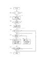
次に、トナーボトルTYを動作させるための、CPU50による駆動モータ40の制御フローについて、図14のフローチャートに基づいて説明する。なお、以下の説明においてイエローのトナーボトルTYについての制御フローを説明するが、他のトナーボトルTM,TC,TKについても、制御対象(駆動部DM,DC,DKの駆動モータ)が異なる以外は同様の制御を実行可能である。また、以下の制御フローは、装置本体101に設けられた記憶媒体に保存されたプログラムをCPU50がメモリRMに読み出されることで実行される。
[Toner bottle operation control]
Next, a control flow of the
CPU50は、装置本体101の電源がONされた場合、又は前の画像形成プロセスが完了した場合等にこの制御フローを開始し(STEP1)、メモリRMの情報を参照して装置本体101が設置シーケンスを完了しているか否かを判断する(STEP2)。例えば、装置本体101の設置シーケンスとは、例えば工場から出荷されてから初めて通電された場合等、画像形成装置100が初期状態にある場合に行う一連の調整作業である。
The
設置シーケンスの調整作業には、トナーボトルTYの解除動作、濃度検出センサの光量調整、及び現像装置15Yの初期化が含まれる。光量調整とは、光学式の濃度検出センサ29の調整作業であり、例えば、所定の光量の下で濃度検出センサ29が検知する受光量が予め設定された値となるように調整する。また、現像装置の初期化には、例えば現像装置15Yの内部の現像剤を撹拌して容器内部のT/D比を均一化するなどして、現像装置15Yのトナー濃度を調整する現像剤濃度調整が含まれる。設置シーケンスが完了すると、メモリRMには設置シーケンスの完了を表す設置情報が書き込まれる。
The adjustment operation of the installation sequence includes the toner bottle TY releasing operation, the light amount adjustment of the density detection sensor, and the initialization of the developing
設置シーケンスが未完である場合(STEP2:No)、CPU50は予め設定された値の第1デューティ比DW1の信号(第1の初期入力値)を駆動モータ40に入力し、フィードフォワード制御により駆動モータ40を制御する(STEP3)。この第1デューティ比DW1の値は、STEP3における回転速度が目標回転数N1=60[rpm]となるように、出荷前に予め設定されたものである。
When the installation sequence is incomplete (STEP 2: No), the
CPU50は、位相センサTSからの信号によって、ポンプ部20bの所定回数(本実施形態においては1回)のポンプ動作に相当するギヤ部20aの所定量の回転を検知するまで駆動モータ40の駆動を継続する(STEP4)。これにより、駆動モータ40からトナーボトルTYに与えられた駆動力の一部を利用して、解除装置30が排出口シャッタ4を閉位置から開位置へと移動させ、設置シーケンスの一部を構成するトナーボトルTYの開封が自動で実行される。そして、ポンプ部20bが所定量回転したことを確認すると(STEP4:Yes)、駆動モータ40の駆動を停止する。このとき、CPU50はSTEP3においてトナーボトルTYが最後に半回転した際(ポンプ部20bの最後に伸縮動作した際)のポンプ動作1回分の所要時間TiとしてメモリRMに記録する(STEP5)。
The
なお、解除装置30の解除動作に要する駆動モータ40の回転量は、ポンプ部20bのポンプ動作1回に相当する回転量より多く(少なく)設定してもよい。また、本実施形態においては、フィードフォワード制御により駆動モータ40を回転させて解除装置30に解除動作を実行させているが、フィードバック制御により解除動作を実行させてもよい。すなわち、CPU50は駆動モータ40に第1デューティ比DW1の信号を入力した後、位相センサTSからの信号に基づいて、トナーボトルTYの回転速度が目標回転数N1に近付くように駆動モータ40への入力信号を修正する構成としてもよい。
Note that the rotation amount of the
次に、CPU50はトナー消費量の推定値又は現像容器内部のT/D比等に基づいてトナー補給の必要性を判断して(STEP6)、補給回数(ポンプ部20bの伸縮回数)を決定する。CPU50は、例えば画像情報からビデオカウント値を計測することによってトナーの消費量を推定している。ただし、ビデオカウント値とは、トナー色毎に画像データの1画素ごとの濃度値を画像1面分積算したものである。また、現像容器内部のT/D比は、例えば現像容器16Yに設けられたトナー濃度センサ19Yの検出値等に基づいて判断される。
Next, the
トナー補給の必要がある場合、CPU50は解除装置30の解除動作後初の補給かどうかを判断する(STEP7)。解除動作後初の補給である場合(STEP7:Yes)には、CPU50は第2デューティ比DW2の信号(第2の初期入力値)を駆動モータ40に入力して、トナーボトルTYをポンプ動作1回分の回転量で回転させる(STEP8)。また、位相センサTSからの信号に基づいて、第2デューティ比DW2の下でポンプ動作1回に要した時間Tiを更新すると共に、第2デューティ比DW2の値を前回デューティ比DW3としてメモリRMに書き込む。
When the toner needs to be replenished, the
ここで、解除動作を行う場合と排出動作を行う場合とで駆動モータ40へのトルク負荷が異なることを説明する。解除動作を行う場合(STEP3)には、トナーボトルTYを回転させる負荷と解除装置30を介して排出口シャッタ4を移動させる負荷とを合わせた負荷トルクが駆動モータ40に作用する。その一方で、補給動作を行う場合(STEP8)には、排出口シャッタ4への駆動入力が遮断されており、解除装置30のスライドギヤ44は無負荷で回転する状態にある。このため、STEP8の補給動作(排出動作)において駆動モータ40に作用するトルク負荷は、STEP3の解除動作(初期動作)におけるトルク負荷に比して小さい。
Here, it will be described that the torque load on the
そこで、解除動作後最初の補給における駆動モータ40への入力値である第2デューティ比DW2は、上述したTi及びDW1を用いて、次の式(1)によって決定される。
DW2=α×(Ti/Tt)×DW1・・・(1)
Therefore, the second duty ratio DW2 that is an input value to the
DW2 = α × (Ti / Tt) × DW1 (1)
ただし、Ttはポンプ動作1回当たりの所要時間についてのターゲット時間であり、排出動作時の目標回転数N2(所定速度)に基づいて決定される。排出動作時の目標回転数N2は、解除動作時の目標回転数N1と等しく設定されている(N2=N1=60[rpm])ため、Tt=0.5(sec)である。αは1より小さい正の定数であり、本実施形態においてはα=0.7である。 However, Tt is the target time for the required time per pump operation, and is determined based on the target rotational speed N2 (predetermined speed) during the discharging operation. Since the target rotational speed N2 during the discharging operation is set equal to the target rotational speed N1 during the releasing operation (N2 = N1 = 60 [rpm]), Tt = 0.5 (sec). α is a positive constant smaller than 1, and α = 0.7 in the present embodiment.
αの値はこれに限らず、STEP3とSTEP8とにおける駆動モータ40へのトルク負荷の差を考慮して0<α<1の範囲で適宜設定可能である。要するに、STEP8における前回のポンプ動作1回当たりの所要時間をT1とし、STEP9における前回のポンプ動作1回当たりの所要時間をT2として、T1とT2とが等しい場合に、次の式(2)が満たされる関係であればよい。
(DW2/DW1)<(DW4/DW3)・・・(2)
The value of α is not limited to this, and can be set as appropriate in the range of 0 <α <1 in consideration of the difference in torque load on the
(DW2 / DW1) <(DW4 / DW3) (2)
式(2)より、第1デューティ比DW1の下でのギヤ部20aの回転速度が目標回転数N1に比して遅い場合(Ti>Tt)には、第2デューティ比DW2の値は係数αと第1デューティ比DW1との積に比して大きく設定される。また、ギヤ部20aの回転速度が目標回転速度に比して速い場合(Ti<Tt)には、第2デューティ比DW2の値は係数αと第1デューティ比DW1との積に比して小さく設定される。また、CPU50は第1デューティ比DW1の下でのポンプ動作1回当たりの所要時間が目標値以下である場合には、所要時間が目標値より大きい場合よりも駆動モータ40の出力トルクが大きくなるように第2デューティ比DW2を修正する。これにより、解除動作後初の排出動作時にギヤ部20aが回転駆動されるときの回転速度は、目標回転数N2に近付くように制御されている。なお、STEP8における第2デューティ比DW2の値を解除動作におけるトナーボトルTYに依存させることなく、予め設定された値を用いる構成としてもよい。
From equation (2), when the rotational speed of the
STEP7において、解除動作後初の補給ではない場合(STEP7:No)、すなわち排出口21aが開かれてから2回目以降の補給動作の場合、CPU50はSTEP9に進む。STEP9では、CPU50は前回デューティ比DW3を用いて、次の式(3)によって今回の補給動作における入力値(今回デューティ比DW4)を決定し、駆動モータ40をポンプ動作1回分の回転量で駆動する(STEP9)。
DW4=Ti/Tt×DW3・・・(3)
In STEP7, when it is not the first replenishment after the release operation (STEP7: No), that is, in the second and subsequent replenishment operations after the
DW4 = Ti / Tt × DW3 (3)
式(3)より、前回デューティ比DW3の下でのギヤ部20aの回転速度が目標回転数N2に比して遅い場合(Ti>Tt)には、今回デューティ比DW4の値は前回デューティ比DW3に比して大きく設定される(DW4>DW3)。また、ギヤ部20aの回転速度が目標回転速度に比して速い場合(Ti<Tt)には、今回デューティ比DW4の値は前回デューティ比DW3に比して小さく設定される(DW4<DW3)。言い換えると、CPU50は前回デューティ比DW3の下でのポンプ動作1回当たりの所要時間が目標値以下である場合には、所要時間が目標値より大きい場合よりも出力トルクが大きくなるように駆動モータ40を制御する。これにより、補給動作時にギヤ部20aが回転駆動されるときの回転速度は、目標回転数N2に近付くように制御されている。
From equation (3), when the rotational speed of the
STEP8及びSTEP9において、CPU50は位相センサTSからの検知信号に基づいて、ポンプ動作1回分の所要時間Tiを更新すると共に、今回のデューティ比(DW2又はDW4)の値を前回デューティ比DW3に代入して更新する。また、CPU50はポンプ動作の実行回数をカウントし、この実行回数がSTEP6で定めた補給回数に到達したかどうかを判断する(STEP10)。実行回数が不足である場合にはSTEP7に戻ってポンプ動作を繰り返し実行させる。
In STEP8 and STEP9, the
最後に、CPU50はポンプ動作の実行回数がSTEP6で定めた補給回数に到達したことを確認すると(STEP10:Yes)、トナーボトルTYの制御を終了する(STEP11)と共に、次の制御開始に備えて待機する。
Finally, when the
なお、装置本体101の設置シーケンスにおいて、トナーボトルTY,TM,TC,TKの解除動作は、光量調整の後に行われる。また、トナーボトルTY,TM,TC,TKのそれぞれの開封作業は、対応する現像装置15Y,15M,15C,15Kの初期化の後に行われる。この初期化は現像装置15Yからイエロー、マゼンタ、シアン、ブラックの順に現像装置15Kまで順に行われ、トナーボトルTY,TM,TC,TKの解除動作もこの順に行われる。このとき、先行して初期化の終了した現像装置に対応するトナーボトル(例えばトナーボトルTY)の解除動作は、後続する現像装置(例えば現像装置15M)の初期化に並行して行われている。
In the installation sequence of the apparatus
[本実施形態の効果]
本実施形態に係る画像形成装置100において、上述したように排出動作時(STEP7〜STEP10)の駆動モータ40の出力は、回転速度が目標回転数N2に近付くようにフィードバック制御される。これにより、ポンプ動作毎にトナーボトルTYから排出されるトナー量を安定させることができ、現像装置にトナーを安定的に補給することができる。そして、このような構成において、収容容器を回転させる駆動装置により開閉部材を移動させて排出口を開ける場合に、開閉部材を開けた後に収容容器の回転が不安定になることを防ぐことができる。以下、イエローのトナーボトルTYを例にして具体的に説明する。
[Effect of this embodiment]
In the
まず、比較例として、CPU50が解除動作と補給動作とに亘る一連のフィードバック制御によって駆動モータ40を制御する構成を考える。すなわち、CPU50が所定の初期入力値を駆動モータ40に入力して解除装置30に排出口シャッタ4を開位置へと移動させた後、駆動モータ40への入力信号をリセットすることなくフィードバック制御を継続する構成である。この場合、解除動作において駆動モータ40に作用するトルク負荷と、補給動作において駆動モータ40に作用するトルク負荷との違いによって、排出口21aが開かれた直後に駆動モータ40の回転速度が大きく変化する虞がある。この場合、駆動モータ40の回転速度がフィードバック制御によって目標回転数に収束するまでの時間が長くなり、トナーボトルTYの回転速度が不安定になってしまう。そして、トナーボトルTYから排出される現像剤量のばらつきが大きくなると、現像装置内部のトナー濃度が大きく変動してしまい、画像の品位低下につながる虞がある。
First, as a comparative example, consider a configuration in which the
一方、本実施形態では、第1デューティ比DW1の信号(第1の初期入力値)を用いて解除動作(初期動作)を開始した後、第1デューティ比DW1とは異なる第2デューティ比DW2の信号(第2の初期入力値)を用いて補給動作(排出動作)を開始する。このため、解除動作と補給動作とのトルク負荷の違いに応じて初期入力値(DW1,DW2)を設定することで、解除動作から補給動作に移行する際にトナーボトルTYの回転速度が大きく変動することを防ぐことができる。これにより、トナーボトルTYを目標回転数N2に近い速度で回転させて、安定した量の現像剤を排出させることが可能となり、必要な量の現像剤を現像装置15Yに確実に補給することができる。
On the other hand, in this embodiment, after starting the release operation (initial operation) using the signal (first initial input value) of the first duty ratio DW1, the second duty ratio DW2 different from the first duty ratio DW1 The replenishment operation (discharge operation) is started using the signal (second initial input value). Therefore, by setting the initial input values (DW1, DW2) according to the difference in torque load between the release operation and the replenishment operation, the rotation speed of the toner bottle TY varies greatly when shifting from the release operation to the replenishment operation. Can be prevented. As a result, the toner bottle TY can be rotated at a speed close to the target rotation speed N2, and a stable amount of developer can be discharged, so that a necessary amount of developer can be reliably supplied to the developing
また、比較例のようにトナーボトルTYの回転速度が大きく変動する構成では、トナーボトルTY及び駆動モータ40の振動が装置本体101の部品(例えば、カートリッジ式の画像形成部PY)の共振周波数帯に重なってしまう可能性がある。このような部品が駆動モータ40及びトナーボトルTYと共振して大きく振動すると、装置の稼働音が増大するのみならず、解除動作に並行して行われる調整作業に影響を及ぼす虞がある。例えば、中間転写ベルト7に振動が伝わることで、濃度検出センサ29による制御パッチの濃度検出が妨げられる可能性がある。本実施形態では、解除動作から補給動作に移行する際にトナーボトルTYの回転速度の変動が低減されるため、このような不都合を回避することができる。
Further, in the configuration in which the rotation speed of the toner bottle TY varies greatly as in the comparative example, the vibration of the toner bottle TY and the
さらに、本実施形態では、解除動作におけるトナーボトルTYの回転速度(ポンプ動作1回分の所要時間Ti)に基づいて、第2デューティ比DW2を修正する制御(図14のSTEP8参照)を行っている。これにより、固定値のデューティ比を用いて補給動作を開始する構成に比して、トナーボトルTYの回転速度を目標回転数N2に一層素早く収束させることができる。
Furthermore, in this embodiment, control for correcting the second duty ratio DW2 (see
また、トナーボトルTYの封止を解除する解除動作は、光学式濃度センサの光量調整及び現像装置15Yの初期化後に行われる。このため、解除動作に伴う振動が光量調整及び現像装置15Yの初期化に影響を及ぼすことを防ぐことができる。
The releasing operation for releasing the sealing of the toner bottle TY is performed after adjusting the light amount of the optical density sensor and initializing the developing
また、複数設けられた現像装置の初期化は、現像装置15Yから現像装置15Kまで、中間転写ベルト7の搬送方向に並んだ順に実行され、トナーボトルTY,TM,TC,TKの解除動作も同じ順に実行される。そして、例えばトナーボトルTYの解除動作は現像装置15Mの初期化に並行して実行されるなど、先行して初期化が完了した現像装置に対応するトナーボトルの解除動作は、後続する現像装置の初期化に並行して実行される。これにより、設置シーケンスの所要時間を短縮することができ、画像形成プロセスの開始や補給動作の開始に迅速に備えることができる。
The initialization of the plurality of developing devices is executed in the order in which the developing
本発明は、中間転写タンデム方式のカラー画像形成装置として適用したが、現像剤収容容器を備えた他の方式の画像形成装置にも同様に適用可能である。なお、現像剤収容容器の構成は上述したものに限らず、回転動作に伴って内部の現像剤を排出可能に構成されたものであればよく、例えばトナーボトルに内蔵されたスクリュ等、ベローズ式のポンプ機構以外の排出機構を備えたものであってもよい。 The present invention is applied as an intermediate transfer tandem type color image forming apparatus, but can be similarly applied to other types of image forming apparatuses including a developer container. Note that the configuration of the developer container is not limited to that described above, and may be any as long as the developer can be discharged along with the rotation operation. For example, a screw incorporated in a toner bottle, a bellows type A discharge mechanism other than the pump mechanism may be provided.
1Y,1M,1C,1K…像担持体(感光ドラム)/4…シャッター部材(排出口シャッタ)/7…中間転写体(中間転写ベルト)/15Y,15M,15C,15K…現像装置/20a…ボトルギヤ(ギヤ部)/20b…ポンプ部/20k…収容部(円筒部)/21a…排出口/22…カム機構/29…トナー濃度検知手段(濃度検出センサ)/30…移動機構(解除装置)/31…係合部材(スライド部材)/40…駆動装置(駆動モータ)/44…駆動伝達機構、駆動ギヤ(スライドギヤ)/45…駆動伝達機構、ウォームギヤ/50…制御手段(CPU)/100…画像形成装置/DW1…第1の初期入力値(第1デューティ比)/DW2…第2の初期入力値(第2デューティ比)/TS…検知手段(位相センサ)/TY,TM,TC,TK…収容容器(トナーボトル)/S…記録材 1Y, 1M, 1C, 1K ... Image carrier (photosensitive drum) / 4 ... Shutter member (discharge port shutter) / 7 ... Intermediate transfer member (intermediate transfer belt) / 15Y, 15M, 15C, 15K ... Developing device / 20a ... Bottle gear (gear part) / 20b ... pump part / 20k ... accommodating part (cylindrical part) / 21a ... discharge port / 22 ... cam mechanism / 29 ... toner concentration detection means (density detection sensor) / 30 ... moving mechanism (release device) / 31 ... engaging member (slide member) / 40 ... drive device (drive motor) / 44 ... drive transmission mechanism, drive gear (slide gear) / 45 ... drive transmission mechanism, worm gear / 50 ... control means (CPU) / 100 ... Image forming apparatus / DW1 ... first initial input value (first duty ratio) / DW2 ... second initial input value (second duty ratio) / TS ... detecting means (phase sensor) / TY, TM TC, TK ... accommodating container (toner bottle) / S ... recording material
Claims (14)
装置本体と、 The device body;
駆動装置と、 A driving device;
制御手段と、 Control means;
前記装置本体の装着部に装着可能であり、トナーを収容し、収容されたトナーを排出する排出部を有し、前記駆動装置から供給される駆動力により回転駆動されるトナーボトルと、 A toner bottle that can be mounted on the mounting portion of the apparatus main body, has a discharge portion that stores toner and discharges the stored toner, and is rotationally driven by a driving force supplied from the driving device;
前記トナーボトルが所定回数回転したことに関する情報を検知する検知部と、 A detector that detects information related to the toner bottle rotating a predetermined number of times;
前記トナーボトルに設けられ、前記排出部が遮蔽される遮蔽位置と前記排出部が開放される開放位置との間で移動可能なシャッター部材と、 A shutter member provided on the toner bottle and movable between a shielding position where the discharge portion is shielded and an open position where the discharge portion is opened;
前記トナーボトルに設けられ、前記装着部に前記トナーボトルが装着された状態で前記駆動力が入力されるボトルギヤと、 A bottle gear which is provided in the toner bottle and receives the driving force in a state where the toner bottle is mounted on the mounting portion;
前記装置本体に設けられ、前記装着部に前記トナーボトルが装着された状態で前記ボトルギヤの回転動作に伴って前記シャッター部材を前記遮蔽位置から前記開放位置に移動させるための移動機構と、 A moving mechanism provided in the apparatus main body for moving the shutter member from the shielding position to the open position in accordance with a rotation operation of the bottle gear in a state where the toner bottle is mounted in the mounting portion;
前記トナーボトルに設けられ、前記装着部に前記トナーボトルが装着された状態で前記ボトルギヤの回転動作に伴って前記排出部から所定量のトナーを排出するための排出機構と、 A discharge mechanism that is provided in the toner bottle and discharges a predetermined amount of toner from the discharge unit in accordance with a rotation operation of the bottle gear in a state where the toner bottle is mounted in the mounting unit;
を備え、 With
前記制御手段は、前記ボトルギヤに前記駆動力が入力されてから、前記トナーボトルが前記所定回数回転したことに関する情報を前記検知部が検知するまでの間の、前記ボトルギヤに入力される前記駆動力の大きさよりも、前記ボトルギヤに前記駆動力が入力されてから、前記トナーボトルが前記所定回数回転したことに関する情報を前記検知部が検知した後、前記排出機構が前記排出部から前記所定量のトナーを最初に排出する際の、前記ボトルギヤに入力される前記駆動力の大きさの方が小さくなるように、前記駆動装置を制御する The control means is configured to input the driving force input to the bottle gear from when the driving force is input to the bottle gear to when the detection unit detects information related to the toner bottle rotating the predetermined number of times. Than when the driving force is input to the bottle gear, the detection unit detects information about the rotation of the toner bottle a predetermined number of times, and then the discharge mechanism detects the predetermined amount from the discharge unit. The driving device is controlled so that the magnitude of the driving force input to the bottle gear when the toner is first discharged becomes smaller.
ことを特徴とする画像形成装置。 An image forming apparatus.
ことを特徴とする請求項1に記載の画像形成装置。 The image forming apparatus according to claim 1.
前記装着部に前記トナーボトルが装着された状態で前記ボトルギヤの回転動作に伴って前記ポンプ部の伸縮動作が実行されることにより、前記排出部から前記所定量のトナーを排出する The predetermined amount of toner is discharged from the discharge portion by performing an expansion / contraction operation of the pump portion in accordance with the rotation operation of the bottle gear while the toner bottle is attached to the attachment portion.
ことを特徴とする請求項1又は2に記載の画像形成装置。 The image forming apparatus according to claim 1, wherein the image forming apparatus is an image forming apparatus.
ことを特徴とする請求項3に記載の画像形成装置。 The image forming apparatus according to claim 3.
装置本体と、 The device body;
駆動装置と、 A driving device;
制御手段と、 Control means;
前記装置本体の装着部に装着可能であり、トナーを収容し、収容されたトナーを排出する排出部を有し、前記駆動装置から供給される駆動力により回転駆動されるトナーボトルと、 A toner bottle that can be mounted on the mounting portion of the apparatus main body, has a discharge portion that stores toner and discharges the stored toner, and is rotationally driven by a driving force supplied from the driving device;
前記トナーボトルの回転に関する情報を検知する検知部と、 A detection unit for detecting information on rotation of the toner bottle;
前記トナーボトルに設けられ、前記排出部が遮蔽される遮蔽位置と前記排出部が開放される開放位置との間で移動可能なシャッター部材と、 A shutter member provided on the toner bottle and movable between a shielding position where the discharge portion is shielded and an open position where the discharge portion is opened;
前記トナーボトルに設けられ、前記装着部に前記トナーボトルが装着された状態で前記駆動力が入力されるボトルギヤと、 A bottle gear which is provided in the toner bottle and receives the driving force in a state where the toner bottle is mounted on the mounting portion;
前記装置本体に設けられ、前記装着部に前記トナーボトルが装着された状態で前記ボトルギヤの回転動作に伴って前記シャッター部材を前記遮蔽位置から前記開放位置に移動させるための移動機構と、 A moving mechanism provided in the apparatus main body for moving the shutter member from the shielding position to the open position in accordance with a rotation operation of the bottle gear in a state where the toner bottle is mounted in the mounting portion;
前記トナーボトルに設けられ、前記装着部に前記トナーボトルが装着された状態で前記ボトルギヤの回転動作に伴って前記排出部から所定量のトナーを排出するための排出機構と、 A discharge mechanism that is provided in the toner bottle and discharges a predetermined amount of toner from the discharge unit in accordance with a rotation operation of the bottle gear in a state where the toner bottle is mounted in the mounting unit;
を備え、 With
前記制御手段は、前記ボトルギヤに前記駆動力が入力されてから前記検知部が前記トナーボトルの回転に関する情報を所定回数検知するまでの間の、前記ボトルギヤに入力される前記駆動力の大きさよりも、前記ボトルギヤに前記駆動力が入力されてから前記検知部が前記トナーボトルの回転に関する情報を前記所定回数検知した後、前記排出機構が前記排出部から前記所定量のトナーを最初に排出する際の、前記ボトルギヤに入力される前記駆動力の大きさの方が小さくなるように前記駆動装置を制御する The control means is configured to be larger than the magnitude of the driving force input to the bottle gear from when the driving force is input to the bottle gear until the detection unit detects information related to rotation of the toner bottle a predetermined number of times. When the discharge unit first discharges the predetermined amount of toner from the discharge unit after the detection unit detects information about rotation of the toner bottle a predetermined number of times after the driving force is input to the bottle gear. The driving device is controlled so that the magnitude of the driving force input to the bottle gear becomes smaller.
ことを特徴とする画像形成装置。 An image forming apparatus.
ことを特徴とする請求項5に記載の画像形成装置。 The image forming apparatus according to claim 5.
前記装着部に前記トナーボトルが装着された状態で前記ボトルギヤの回転動作に伴って前記ポンプ部の伸縮動作が実行されることにより、前記排出部から前記所定量のトナーを排出する The predetermined amount of toner is discharged from the discharge portion by performing an expansion / contraction operation of the pump portion in accordance with the rotation operation of the bottle gear while the toner bottle is attached to the attachment portion.
ことを特徴とする請求項5又は6に記載の画像形成装置。 The image forming apparatus according to claim 5, wherein the image forming apparatus is an image forming apparatus.
ことを特徴とする請求項7に記載の画像形成装置。 The image forming apparatus according to claim 7.
装置本体と、 The device body;
駆動装置と、 A driving device;
制御手段と、 Control means;
前記装置本体の装着部に装着可能であり、トナーを収容し、収容されたトナーを排出する排出部を有し、前記駆動装置から供給される駆動力により回転駆動されるトナーボトルと、 A toner bottle that can be mounted on the mounting portion of the apparatus main body, has a discharge portion that stores toner and discharges the stored toner, and is rotationally driven by a driving force supplied from the driving device;
前記トナーボトルに設けられ、前記排出部が遮蔽される遮蔽位置と前記排出部が開放される開放位置との間で移動可能なシャッター部材と、 A shutter member provided on the toner bottle and movable between a shielding position where the discharge portion is shielded and an open position where the discharge portion is opened;
前記トナーボトルに設けられ、前記装着部に前記トナーボトルが装着された状態で前記駆動力が入力されるボトルギヤと、 A bottle gear which is provided in the toner bottle and receives the driving force in a state where the toner bottle is mounted on the mounting portion;
前記装置本体に設けられ、前記装着部に前記トナーボトルが装着された状態で前記ボトルギヤの回転動作に伴って前記シャッター部材を前記遮蔽位置から前記開放位置に移動させるための移動機構と、 A moving mechanism provided in the apparatus main body for moving the shutter member from the shielding position to the open position in accordance with a rotation operation of the bottle gear in a state where the toner bottle is mounted in the mounting portion;
前記トナーボトルに設けられ、前記装着部に前記トナーボトルが装着された状態で前記ボトルギヤの回転動作に伴って前記排出部から所定量のトナーを排出するための排出機構と、 A discharge mechanism that is provided in the toner bottle and discharges a predetermined amount of toner from the discharge unit in accordance with a rotation operation of the bottle gear in a state where the toner bottle is mounted in the mounting unit;
を備え、 With
前記制御手段は、前記移動機構が前記シャッター部材を前記遮蔽位置から前記開放位置に移動させるまでの間の、前記ボトルギヤに入力される前記駆動力の大きさよりも、前記移動機構が前記シャッター部材を前記遮蔽位置から前記開放位置に移動させた後、前記排出機構が前記排出部から前記所定量のトナーを最初に排出する際の、前記ボトルギヤに入力される前記駆動力の大きさの方が小さくなるように前記駆動装置を制御する The control means is configured so that the moving mechanism causes the shutter member to move more than the magnitude of the driving force input to the bottle gear until the moving mechanism moves the shutter member from the shielding position to the open position. After the movement from the shielding position to the open position, the driving force input to the bottle gear when the discharging mechanism first discharges the predetermined amount of toner from the discharging portion is smaller. Control the drive so that
ことを特徴とする画像形成装置。 An image forming apparatus.
前記駆動伝達機構は、前記シャッター部材が前記遮蔽位置から前記開放位置に移動するまでの間は、前記ボトルギヤに入力される前記駆動力を前記移動機構に伝達し、前記シャッター部材が前記遮蔽位置から前記開放位置に移動した後は、前記ボトルギヤに入力される前記駆動力を前記移動機構に伝達しない The drive transmission mechanism transmits the driving force input to the bottle gear to the moving mechanism until the shutter member moves from the shield position to the open position, and the shutter member moves from the shield position. After moving to the open position, the driving force input to the bottle gear is not transmitted to the moving mechanism.
ことを特徴とする請求項1乃至9のいずれか1項に記載の画像形成装置。 The image forming apparatus according to claim 1, wherein the image forming apparatus is an image forming apparatus.
前記制御手段は、パルス幅変調信号を入力することにより、前記ボトルギヤに入力される前記駆動力の大きさを制御する The control means controls the magnitude of the driving force input to the bottle gear by inputting a pulse width modulation signal.
ことを特徴とする請求項1乃至10のいずれか1項に記載の画像形成装置。 The image forming apparatus according to claim 1, wherein the image forming apparatus is an image forming apparatus.
前記トナーボトルが前記装着部に装着された状態において、前記係合部材は、前記駆動ギヤの回転動作に伴って前記シャッター部材が前記遮蔽位置から前記開放位置に移動するよう前記トナーボトルに対して相対移動することが可能である In a state where the toner bottle is mounted on the mounting portion, the engagement member moves the shutter member from the shield position to the open position with the rotation of the drive gear. It is possible to move relative
ことを特徴とする請求項1乃至11のいずれか1項に記載の画像形成装置。 The image forming apparatus according to claim 1, wherein the image forming apparatus is an image forming apparatus.
ことを特徴とする請求項12に記載の画像形成装置。 The image forming apparatus according to claim 12.
前記トナーボトルが前記装着部に装着された状態において、前記係合部材は、前記駆動ギヤの回転動作に伴って前記ウォームギヤと一体にスライド移動することにより、前記トナーボトルに対して相対移動する In a state where the toner bottle is mounted on the mounting portion, the engaging member moves relative to the toner bottle by sliding together with the worm gear as the driving gear rotates.
ことを特徴とする請求項12又は13に記載の画像形成装置。 The image forming apparatus according to claim 12, wherein the image forming apparatus is an image forming apparatus.
Priority Applications (3)
| Application Number | Priority Date | Filing Date | Title |
|---|---|---|---|
| JP2015209870A JP6576208B2 (en) | 2015-10-26 | 2015-10-26 | Image forming apparatus |
| US15/298,602 US10012930B2 (en) | 2015-10-26 | 2016-10-20 | Image forming apparatus having controlled driving force |
| US15/991,102 US10139753B2 (en) | 2015-10-26 | 2018-05-29 | Image forming apparatus having controlled driving force |
Applications Claiming Priority (1)
| Application Number | Priority Date | Filing Date | Title |
|---|---|---|---|
| JP2015209870A JP6576208B2 (en) | 2015-10-26 | 2015-10-26 | Image forming apparatus |
Publications (3)
| Publication Number | Publication Date |
|---|---|
| JP2017083570A JP2017083570A (en) | 2017-05-18 |
| JP2017083570A5 JP2017083570A5 (en) | 2018-12-06 |
| JP6576208B2 true JP6576208B2 (en) | 2019-09-18 |
Family
ID=58558552
Family Applications (1)
| Application Number | Title | Priority Date | Filing Date |
|---|---|---|---|
| JP2015209870A Active JP6576208B2 (en) | 2015-10-26 | 2015-10-26 | Image forming apparatus |
Country Status (2)
| Country | Link |
|---|---|
| US (2) | US10012930B2 (en) |
| JP (1) | JP6576208B2 (en) |
Families Citing this family (3)
| Publication number | Priority date | Publication date | Assignee | Title |
|---|---|---|---|---|
| JP6658652B2 (en) * | 2017-03-30 | 2020-03-04 | 京セラドキュメントソリューションズ株式会社 | Toner container and image forming apparatus |
| CN107678260B (en) * | 2017-10-11 | 2020-01-21 | 中山诚威科技有限公司 | Developing box |
| JP7327040B2 (en) * | 2019-09-25 | 2023-08-16 | 富士フイルムビジネスイノベーション株式会社 | Powder container mounting device, image forming apparatus, and powder container |
Family Cites Families (11)
| Publication number | Priority date | Publication date | Assignee | Title |
|---|---|---|---|---|
| JP4758036B2 (en) | 2001-08-10 | 2011-08-24 | 株式会社リコー | Toner supply device |
| US20030219263A1 (en) * | 2002-05-24 | 2003-11-27 | Toshiba Tec Kabushiki Kaisha | Toner supply device for use in image forming system and method for supplying toner thereto |
| JP5156846B2 (en) | 2011-03-22 | 2013-03-06 | 京セラドキュメントソリューションズ株式会社 | Toner transport device, toner storage container, image forming apparatus, and toner transport device control method |
| JP5825828B2 (en) | 2011-04-20 | 2015-12-02 | キヤノン株式会社 | Image forming apparatus |
| JP2013137499A (en) * | 2011-12-01 | 2013-07-11 | Brother Ind Ltd | Printer |
| JP5574546B2 (en) * | 2012-03-29 | 2014-08-20 | 京セラドキュメントソリューションズ株式会社 | Image forming apparatus and removable developer container mounted thereon |
| JP5744830B2 (en) * | 2012-12-19 | 2015-07-08 | キヤノン株式会社 | Image forming apparatus |
| JP6218506B2 (en) * | 2013-08-30 | 2017-10-25 | キヤノン株式会社 | Image forming apparatus |
| JP6238624B2 (en) * | 2013-07-31 | 2017-11-29 | キヤノン株式会社 | Image forming apparatus |
| JP6173102B2 (en) * | 2013-07-31 | 2017-08-02 | キヤノン株式会社 | Image forming apparatus |
| JP6234293B2 (en) * | 2014-03-25 | 2017-11-22 | キヤノン株式会社 | Image forming apparatus |
-
2015
- 2015-10-26 JP JP2015209870A patent/JP6576208B2/en active Active
-
2016
- 2016-10-20 US US15/298,602 patent/US10012930B2/en active Active
-
2018
- 2018-05-29 US US15/991,102 patent/US10139753B2/en active Active
Also Published As
| Publication number | Publication date |
|---|---|
| US20170115596A1 (en) | 2017-04-27 |
| US10139753B2 (en) | 2018-11-27 |
| JP2017083570A (en) | 2017-05-18 |
| US20180275561A1 (en) | 2018-09-27 |
| US10012930B2 (en) | 2018-07-03 |
Similar Documents
| Publication | Publication Date | Title |
|---|---|---|
| JP5744830B2 (en) | Image forming apparatus | |
| US20180120736A1 (en) | Image forming apparatus | |
| US20180329358A1 (en) | Powder container and image forming apparatus | |
| US10732539B2 (en) | Image forming apparatus | |
| JP6576208B2 (en) | Image forming apparatus | |
| US9298135B2 (en) | Image forming apparatus | |
| JP2017191182A (en) | Powder supply device and image forming apparatus | |
| JP6024540B2 (en) | Developer transport device and image forming apparatus | |
| JP6544169B2 (en) | Developer storage container and image forming apparatus | |
| WO2017191849A1 (en) | Developer replenishment container | |
| JP6584228B2 (en) | Developer supply container | |
| JP2017053962A (en) | Image forming apparatus | |
| JP2015152769A (en) | Developer supply container | |
| JP2016031497A (en) | Toner supply device | |
| US20180239277A1 (en) | Image forming apparatus | |
| JP5315272B2 (en) | Image forming apparatus | |
| JP6576041B2 (en) | Image forming apparatus | |
| JP2021026015A (en) | Developer supply container and developer supply system | |
| JP7395369B2 (en) | Image forming device | |
| JP5959968B2 (en) | Developer storage container and manufacturing method thereof | |
| JP2016224416A (en) | Developer storage container and image forming apparatus | |
| JP2017142452A (en) | Development device | |
| JP6504359B2 (en) | Powder container and image forming apparatus | |
| JP2023060921A (en) | Image forming apparatus | |
| JP6364841B2 (en) | Powder container and image forming apparatus |
Legal Events
| Date | Code | Title | Description |
|---|---|---|---|
| A521 | Request for written amendment filed |
Free format text: JAPANESE INTERMEDIATE CODE: A523 Effective date: 20181023 |
|
| A621 | Written request for application examination |
Free format text: JAPANESE INTERMEDIATE CODE: A621 Effective date: 20181023 |
|
| TRDD | Decision of grant or rejection written | ||
| A977 | Report on retrieval |
Free format text: JAPANESE INTERMEDIATE CODE: A971007 Effective date: 20190717 |
|
| A01 | Written decision to grant a patent or to grant a registration (utility model) |
Free format text: JAPANESE INTERMEDIATE CODE: A01 Effective date: 20190723 |
|
| A61 | First payment of annual fees (during grant procedure) |
Free format text: JAPANESE INTERMEDIATE CODE: A61 Effective date: 20190820 |
|
| R151 | Written notification of patent or utility model registration |
Ref document number: 6576208 Country of ref document: JP Free format text: JAPANESE INTERMEDIATE CODE: R151 |